WO2024181135A1 - 撮像方法、撮像装置、及び、プログラム - Google Patents
撮像方法、撮像装置、及び、プログラム Download PDFInfo
- Publication number
- WO2024181135A1 WO2024181135A1 PCT/JP2024/005158 JP2024005158W WO2024181135A1 WO 2024181135 A1 WO2024181135 A1 WO 2024181135A1 JP 2024005158 W JP2024005158 W JP 2024005158W WO 2024181135 A1 WO2024181135 A1 WO 2024181135A1
- Authority
- WO
- WIPO (PCT)
- Prior art keywords
- image
- imaging
- subject
- captured image
- captured
- Prior art date
- Legal status (The legal status is an assumption and is not a legal conclusion. Google has not performed a legal analysis and makes no representation as to the accuracy of the status listed.)
- Ceased
Links
Images












Classifications
-
- B—PERFORMING OPERATIONS; TRANSPORTING
- B63—SHIPS OR OTHER WATERBORNE VESSELS; RELATED EQUIPMENT
- B63C—LAUNCHING, HAULING-OUT, OR DRY-DOCKING OF VESSELS; LIFE-SAVING IN WATER; EQUIPMENT FOR DWELLING OR WORKING UNDER WATER; MEANS FOR SALVAGING OR SEARCHING FOR UNDERWATER OBJECTS
- B63C11/00—Equipment for dwelling or working underwater; Means for searching for underwater objects
- B63C11/48—Means for searching for underwater objects
-
- G—PHYSICS
- G03—PHOTOGRAPHY; CINEMATOGRAPHY; ANALOGOUS TECHNIQUES USING WAVES OTHER THAN OPTICAL WAVES; ELECTROGRAPHY; HOLOGRAPHY
- G03B—APPARATUS OR ARRANGEMENTS FOR TAKING PHOTOGRAPHS OR FOR PROJECTING OR VIEWING THEM; APPARATUS OR ARRANGEMENTS EMPLOYING ANALOGOUS TECHNIQUES USING WAVES OTHER THAN OPTICAL WAVES; ACCESSORIES THEREFOR
- G03B15/00—Special procedures for taking photographs; Apparatus therefor
-
- H—ELECTRICITY
- H04—ELECTRIC COMMUNICATION TECHNIQUE
- H04N—PICTORIAL COMMUNICATION, e.g. TELEVISION
- H04N23/00—Cameras or camera modules comprising electronic image sensors; Control thereof
- H04N23/60—Control of cameras or camera modules
-
- H—ELECTRICITY
- H04—ELECTRIC COMMUNICATION TECHNIQUE
- H04N—PICTORIAL COMMUNICATION, e.g. TELEVISION
- H04N23/00—Cameras or camera modules comprising electronic image sensors; Control thereof
- H04N23/60—Control of cameras or camera modules
- H04N23/63—Control of cameras or camera modules by using electronic viewfinders
Definitions
- This disclosure relates to an imaging method, imaging device, and program, and in particular to an imaging method, imaging device, and program that enable the acquisition of images suitable for color restoration in underwater imaging.
- 3D reconstruction using images is gaining attention for underwater infrastructure inspection and seafloor mapping. Because the rate of color attenuation varies by wavelength underwater, it is difficult to achieve 3D reconstruction with a high degree of accuracy that includes not only shape but also color.
- a calibration process is performed to remove the effects of reflections from underwater particles from images taken underwater by placing a calibration device in the camera's field of view (see, for example, Patent Document 1).
- an underwater camera has been proposed that performs color correction so that color reproducibility is closer to true natural color reproduction, eliminating the need for image processing in post-processing (see, for example, Patent Document 2).
- This disclosure has been made in light of these circumstances, and makes it possible to obtain images suitable for color restoration during underwater imaging.
- An imaging method is an imaging method in which an imaging device acquires an image of an underwater subject captured by at least one imaging sensor, determines whether the image is suitable for color restoration, and outputs correction information for changing the relative position of the subject according to the determination result.
- An imaging device is an imaging device that includes at least one imaging sensor that captures an image of an underwater subject and outputs the captured image, and a determination unit that determines whether the captured image is suitable for color restoration and outputs correction information for changing the relative position of the subject depending on the determination result.
- the program of one aspect of the present disclosure is for executing a process of acquiring an image of an underwater subject captured by at least one imaging sensor, determining whether the image is suitable for color restoration, and outputting correction information for changing the relative position of the subject depending on the determination result.
- an image of an underwater subject is captured by at least one imaging sensor, a determination is made as to whether the captured image is suitable for color restoration, and correction information for changing the relative position of the subject is output according to the determination result.
- the imaging device of one aspect of the present disclosure may be an independent device or an internal block constituting a single device.
- the program of one aspect of the present disclosure may be provided by transmitting it via a transmission medium or by recording it on a recording medium.
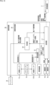
- FIG. 1 is a block diagram showing an example configuration of an imaging device according to a first embodiment of the present disclosure.
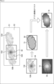
- FIG. 4 is a diagram illustrating processing performed by the imaging device according to the first embodiment.
- FIG. 2 is a diagram illustrating a display example of a display of the imaging device.
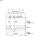
- FIG. 13 is a diagram showing an example of an imaging plan for an imaging device. This is a cross-sectional view of the imaging position viewed from the lateral direction relative to the water surface. 5 is a diagram for explaining a state in which imaging processing is executed according to the imaging plan of FIG. 4 .
- FIG. 4 is a diagram illustrating processing performed by the imaging device according to the first embodiment.
- FIG. 2 is a diagram illustrating a display example of a display of the imaging device.
- FIG. 13 is a diagram
- FIG. 2 is a diagram illustrating a first example of the configuration of a storage unit of the imaging device.
- FIG. 2 is a diagram showing a first data configuration example of imaging data.
- FIG. 13 is a diagram illustrating a second example of the configuration of the storage unit of the imaging device.
- FIG. 11 is a diagram showing a second data configuration example of the imaging data.
- FIG. 11 is a block diagram showing an example configuration of an imaging device according to a second embodiment of the present disclosure.
- 1A and 1B are diagrams illustrating the advantages of an imaging device in which a display is separated from a device body.
- 11A and 11B are diagrams illustrating changes in the attitude of the imaging device.
- 11A and 11B are diagrams illustrating changes in the attitude of the imaging device.
- FIG. 13 is a block diagram showing an example configuration of an imaging device according to a third embodiment of the present disclosure. 13 is a flowchart illustrating an imaging process performed by an imaging device according to a third embodiment. FIG. 13 is a block diagram showing an example configuration of an imaging device according to a fourth embodiment of the present disclosure.
- FIG. 13 is a block diagram showing an example configuration of an imaging device according to a fifth embodiment of the present disclosure. 13 is a flowchart illustrating an image conformity determination process in step S15 of FIG. 7 according to the fifth embodiment.
- FIG. 1 is a block diagram showing an example configuration of an embodiment of a computer to which the technology of the present disclosure is applied.
- FIG. 1 is a block diagram showing an example configuration of a first embodiment of an imaging device to which the technology of the present disclosure is applied.
- the imaging device 1 shown in FIG. 1 is a device that captures an image of a subject underwater to generate a captured image, and in particular is an imaging device that can generate captured images that improve the quality of color restoration (reproduction).
- the captured images generated by the imaging device 1 are RGB images (color images) that are output to a 3D reconstruction processing device 2 and used, for example, for 3D reconstruction such as underwater infrastructure inspection and seabed mapping.
- the imaging device 1 has two imaging sensors 11 (imaging sensor 11R, imaging sensor 11L), a timing generator 12, a lighting device 13, a depth meter 14, a turbidity meter 15, an image processing unit 16, a memory unit 17, and a display 18.
- the image processing unit 16 has a preprocessing unit 21 and a determination unit 22.
- the two imaging sensors 11 are arranged in parallel at a fixed distance apart to form a stereo camera.
- imaging sensor 11R is the imaging sensor arranged on the right side
- imaging sensor 11L is the imaging sensor arranged on the left side.
- the imaging sensors 11R and 11L capture images of a subject in synchronization with a synchronization signal from a timing generator 12, and supply the resulting captured images to a pre-processing unit 21.
- captured image R
- captured image (L) When distinguishing between the captured images generated by imaging sensors 11R and 11L, they are simply referred to as captured images.
- the timing generator 12 supplies a synchronization signal that controls the imaging timing to the imaging sensor 11R, the imaging sensor 11L, the depth meter 14, and the turbidity meter 15 based on a control signal from an operation unit (not shown).
- the operation unit has an imaging button, etc., and when a command to start imaging is issued by a user operation, the operation unit supplies a control signal to the timing generator 12 to output a synchronization signal.
- the lighting device 13 has a light-emitting source such as an LED (Light Emitting Diode), and illuminates the periphery of the imaging range of the imaging sensor 11 based on user operations performed on the operation unit. For example, the user turns on the lighting when there is insufficient light underwater, and turns it off when there is sufficient light. If the imaging device 1 is used only in imaging environments with sufficient light, the lighting device 13 can be omitted.
- a light-emitting source such as an LED (Light Emitting Diode)
- LED Light Emitting Diode
- the depth meter 14 measures the depth [m] from the sea surface and supplies this as the depth to the memory unit 17.
- the timing of the measurement is synchronized with the imaging timing of the image sensor 11 based on a synchronization signal from the timing generator 12.
- the amount of attenuation of light in water varies depending on the wavelength. Depth information is useful for color restoration, as it can be used to estimate how much of each color of light contained in sunlight remains.
- the turbidity meter 15 measures the turbidity [NTU] in the water and supplies the result to the memory unit 17.
- the timing of the measurement is synchronized with the imaging timing of the image sensor 11 based on a synchronization signal from the timing generator 12.
- turbidity can be used to estimate the amount of attenuation of blue, making it useful information for color restoration.
- the image processing unit 16 is composed of, for example, a CPU (Central Processing Unit), an MPU (Micro Processing Unit) or a DSP (Digital Signal Processor), and has a pre-processing unit 21 and a judgment unit 22.
- a CPU Central Processing Unit
- MPU Micro Processing Unit
- DSP Digital Signal Processor
- the pre-processing unit 21 performs pre-processing such as noise reduction processing and scaling processing on the stereo camera images of the captured image (R) and the captured image (L) supplied from the image sensors 11R and 11L as necessary.
- the pre-processing unit 21 also detects corresponding pixels that capture the same subject in the captured image (R) and the captured image (L) and calculates the distance to the subject by detecting parallax information.
- the pre-processing unit 21 then generates a depth image in which a depth value, which is the distance to the subject, is stored as a pixel value, and supplies the depth image to the storage unit 17.
- the pre-processing unit 21 supplies one of the captured image (R) and the captured image (L), for example, the captured image (R), to the storage unit 17 as a representative captured image.
- the captured image supplied to the storage unit 17 may be the captured image (L). Since there is a one-to-one correspondence between the pixels of the captured image and the depth image, it is easy to associate the pixels of the captured image and the depth image in image processing such as semantic segmentation, which will be described later.
- the determination unit 22 is supplied with the captured image, the depth image, and the turbidity from the storage unit 17.
- the depth image and the turbidity are stored in the storage unit 17 in synchronization with the captured image.
- the determination unit 22 uses the captured image, the depth image, and the turbidity from the storage unit 17 to determine whether the captured image is suitable for color restoration. Specifically, the determination unit 22 detects an object that appears in the captured image as a subject, and calculates the distance to the detected object from the depth image. If the object that is the subject in the captured image is captured at a distance suitable for color restoration, the determination unit 22 determines that the captured image is suitable for color restoration.
- the determination unit 22 determines that the captured image is not suitable for color restoration.
- the determination unit 22 supplies suitable/unsuitable information, which is the determination result of whether the captured image is suitable for color restoration, to the storage unit 17 and the display 18. Furthermore, if the determination unit 22 determines that the captured image is not suitable for color restoration, it calculates correction information for moving the imaging position so that the subject is captured at a distance suitable for color restoration. The determination unit 22 superimposes the calculated correction information on the captured image and supplies it to the display 18. If the captured image is suitable for color restoration, it may superimpose information indicating that the image is suitable on the captured image, or it may allow imaging to continue without any special superimposition.
- the storage unit 17 is composed of, for example, a hard disk, a solid state drive (SSD), a RAM disk, a non-volatile memory, etc., and stores various programs and data executed on the imaging device 1.
- the storage unit 17 also stores the captured image and depth image supplied from the preprocessing unit 21, the depth supplied from the depth meter 14, and the turbidity supplied from the turbidity meter 15 as imaging data. If the imaging data stored in the storage unit 17 is all data of captured images suitable for color restoration, the appropriate/unsuitable information, which is the judgment result of whether the captured image is suitable for color restoration, is omitted.
- the appropriate/unsuitable information which is the judgment result of whether the captured image is suitable for color restoration, is also included as imaging data and stored in the storage unit 17.
- the storage unit 17 outputs the imaging data generated by the imaging device 1 to an external device.
- imaging data stored in the storage unit 17, which includes at least the captured image, the depth image, and the depth and turbidity at the time the captured image was acquired are output to the 3D reconstruction processing device 2.
- the connection between the imaging device 1 and the 3D reconstruction processing device 2 is not limited to being wired, and may be wireless.
- the display 18 is formed of a thin display such as an LCD (Liquid Crystal Display) or an organic EL (Electro Luminescence) display, and displays the captured image supplied from the determination unit 22. When correction information is calculated in the determination unit 22, the correction information is superimposed on the captured image and displayed.
- LCD Liquid Crystal Display
- organic EL Electro Luminescence
- the imaging device 1 is configured as described above, captures an image of a subject underwater, and determines whether the captured image obtained as a result is suitable for color restoration. If the captured image is not suitable for color restoration, the imaging device 1 calculates correction information for changing the relative position of the imaging device 1 with respect to the subject, more specifically, the distance between the imaging device 1 and the subject, in order to obtain a suitable image, and displays it on the display 18.
- a user who captures an image using the imaging device 1 can generate an image with improved quality of color restoration (reproduction) by moving the imaging position based on the correction information and capturing an image again. In other words, it is possible to avoid a situation in which there is no captured image that is easy to restore colors after capturing an image.
- the captured image generated by the imaging device 1 is stored in the storage unit 17 and output to an external device (e.g., the 3D reconstruction processing device 2) at a predetermined timing. Capture may be performed periodically at a certain interval from when the user instructs the start of imaging to when the user instructs the end of imaging, or may be performed each time the imaging button is pressed.
- an external device e.g., the 3D reconstruction processing device 2
- Image 51 in Figure 2 is a schematic diagram showing the underwater scene in front of the imaging device 1.
- the field of view (imaging range) FOV of the imaging device 1 captures part of the object 53A.
- a depression 54 that curves away from the imaging device 1 is formed in part of the object 53A that is included in the field of view FOV.
- the imaging sensor 11R captures an image of a part of the object 53A as a subject, generates an image 71R, and supplies it to the pre-processing unit 21.
- the imaging sensor 11L also captures an image of a part of the object 53A, generates an image 71L, and supplies it to the pre-processing unit 21.
- the pre-processing unit 21 generates a depth image 72 using the captured image 71R and the captured image 71L, and supplies it to the storage unit 17.
- the depth image 72 is composed of an image that represents the distance to the subject in 16 bits from 0 to 65535, for example. Specifically, for example, a pixel value of "1" indicates that the distance is 1 cm, and a pixel value of "65535" indicates that the distance is 65535 cm. A pixel value of "0" is invalid. Therefore, the larger the pixel value, the farther the distance to the subject is, and the brighter (whiter) it is represented, so that in the depth image 72, the depth value of the area of the depression 54 is large.
- the pre-processing unit 21 supplies the captured image 71R, which is one of the captured images 71R and 71L, and the depth image 72 to the storage unit 17 for storage.
- the determination unit 22 performs a predetermined object detection process on the captured image 71R to detect the object 53A in the water. For example, the determination unit 22 performs semantic segmentation to distinguish between the pixels of the water 52 and the pixels of the object 53A, thereby detecting the object 53A. The determination unit 22 sets the area of the detected object 53A as a segment SG, as shown in the processed image 73 of the semantic segmentation. The determination unit 22 calculates the distance to the detected object 53A using the result of the semantic segmentation and the depth image 72. Specifically, the determination unit 22 masks the depth image 72 with the segment SG and extracts the depth value of only the object 53A. The mask image 74 is an image in which the depth value of only the object 53A is extracted.
- the determination unit 22 calculates a representative value of the distance to the object 53A using the depth value of the object 53A, and sets it as the distance to the object 53A.
- a method for calculating the representative value of the distance for example, the median, average (filter calculation value), mode, etc. of the depth values of multiple pixels constituting the segment SG can be used.
- the depth value of the center of gravity of the segment SG may be used as the representative value. Note that, for example, if the detected object 53 is donut-shaped and has a hollow center, the center of gravity may be a location where the object 53 does not exist, so when the center of gravity is used, it is necessary to calculate the representative value in combination with other methods.
- the representative value of the distance can be calculated by appropriately combining any statistical method, such as sorting the depth values by value size, excluding the top and bottom several percent as outliers, and calculating the above-mentioned median, average, etc.
- any statistical method such as sorting the depth values by value size, excluding the top and bottom several percent as outliers, and calculating the above-mentioned median, average, etc.
- the determination unit 22 determines whether the captured image 71R of the object 53A is suitable for color restoration as follows. That is, if the distance d to the object 53A calculated using the representative value is included in the optimal distance range (hereinafter referred to as the suitable distance range) of minimum distance value Th_s ⁇ distance d ⁇ maximum distance Th_l, the determination unit 22 determines that the captured image 71R is suitable for color restoration.
- the minimum distance value Th_s can be set to the shortest focal length, for example, and the maximum distance value Th_l can be set to a value obtained by adding a predetermined additional value ⁇ to the shortest focal length (shortest focal length + predetermined additional value ⁇ ).
- the predetermined additional value ⁇ can be changed according to the turbidity of the detected water 52. For example, when the turbidity is high, the predetermined additional value ⁇ is changed so that the suitable distance range becomes narrower.
- the determination unit 22 supplies the storage unit 17 with suitable/unsuitable information, which is the result of the determination as to whether the captured image is suitable for color restoration. If the determination unit 22 determines that the captured image is not suitable for color restoration, it calculates correction information for moving the imaging position so that the subject is captured at a distance suitable for color restoration. For example, the determination unit 22 calculates the amount of movement of the imaging device 1 such that the distance d to the object 53A is the median of the suitable distance range, and displays the correction information on the display 18 by superimposing it on the captured image.
- FIG. 3 shows an example of a display on the display 18, showing an example of a captured image 71R that includes correction information.
- the display 18 displays the captured image 71R.
- a representative position mark 81 is superimposed on the captured image 71R at a pixel position corresponding to a representative value of the distance to the object 53A.
- correction information 82 of "Down 50 cm” is superimposed near the representative position mark 81 to instruct the user to move 50 cm vertically downward.
- the word "NG” is displayed as appropriate/inappropriate information 83 indicating the judgment result, indicating that the current captured image is not suitable for color restoration.
- the user can change the relative position of the imaging device 1 with respect to the subject (for example, by translating and/or rotating the imaging device 1) and capture the image again, thereby acquiring (capturing) an image suitable for color restoration.
- the imaging device 1 captures an image of a subject as described above at one imaging position, and performs an image compatibility determination process to determine whether the captured image is suitable for color restoration.
- the imaging device 1 can also capture images at multiple imaging positions continuously based on an imaging plan.
- Figure 4 shows an example of an imaging plan in which multiple imaging positions are imaged continuously.
- Figure 4 is a plan view of the water surface (ocean surface) seen from directly above.
- imaging positions P1 is set as the starting point, followed by imaging positions P1, P2, P3, ... P16 in order, with imaging position P16 being the final point.
- the 16 imaging positions P1 to P16 are set to image the positions corresponding to the four sides of a rectangle by moving counterclockwise at a predetermined interval.
- Figure 5 shows a cross-sectional view of imaging positions P1 to P4 viewed from the side relative to the water surface.
- imaging positions P1, P3, and P4 are positions where the distance d from the subject (ground surface) is included in the suitable distance range RG_OK.
- suitable distance range RG_OK there is an unsuitable distance range RG_NG_s where the distance is closer, and an unsuitable distance range RG_NG_l where the distance is farther.
- Imaging position P2 is not included in the suitable distance range RG_OK, but is included in the unsuitable distance range RG_NG_l where the distance is farther.
- FIG. 6 shows how the imaging process is performed according to the imaging plan in FIG. 4, and imaging positions P1 to P4 are imaged in sequence.
- the user captures an image at imaging position P1.
- the imaging device 1 captures an image of the subject at imaging position P1 and performs image compatibility determination processing.
- the distance d to the subject is included in the suitable distance range RG_OK, so the captured image is determined to be suitable for color restoration.
- the user moves the imaging device 1 in parallel to the next imaging position P2.
- the imaging device 1 captures an image of the subject at the imaging position P2 and performs an image compatibility determination process.
- the distance d to the subject is not included in the suitable distance range RG_OK, but is included in the longer distance unsuitable distance range RG_NG_l, so the captured image is determined to be unsuitable for color restoration, and correction information for moving the image downward by a predetermined movement amount ⁇ 1 is displayed on the display 18.
- the user moves the imaging device 1 based on the correction information and captures an image.
- the imaging device 1 captures an image of the subject and performs an image compatibility determination process.
- the distance d to the subject is included in the suitable distance range RG_OK, so the captured image is determined to be suitable for color restoration.
- the user moves the imaging device 1 in parallel to the next imaging position P3.
- the user captures an image at the imaging position P3. Since the imaging position P3 is merely moved in parallel from the imaging position P2 in the traveling direction, it is included in the closer distance inappropriate range RG_NG_s, and the captured image is determined to be an image that is not suitable for color restoration. Correction information for moving the image upward by a predetermined movement amount ⁇ 2 is displayed on the display 18. The user moves the imaging device 1 based on the correction information and captures an image. The imaging device 1 captures an image of the subject and performs an image compatibility determination process. As a result of the image compatibility determination process, the distance d to the subject is included in the suitable distance range RG_OK, and therefore the captured image is determined to be an image that is suitable for color restoration. The user moves the imaging device 1 in parallel to the next imaging position P4.
- the user captures an image at imaging position P4.
- the imaging device 1 captures an image of the subject at imaging position P4 and performs image compatibility determination processing.
- the distance d to the subject is within the appropriate distance range RG_OK, so the captured image is determined to be suitable for color restoration.
- the user moves the imaging device 1 in parallel to the next imaging position P5.
- the movement amounts ⁇ 1 and ⁇ 2 as correction information when the distance d to the subject is not included in the optimum distance range RG_OK may be a fixed value determined in advance, or may be a value calculated to be the median value of the optimum distance range RG_OK as described above. In the case of fixed values, the downward movement amount ⁇ 1 and the upward movement amount ⁇ 2 may be the same or different. If the movement amounts ⁇ 1 and ⁇ 2 are small or excessively large, the number of imaging operations increases, so it is desirable to set them appropriately according to the absolute value of the optimum distance range RG_OK. Note that, although an example in which imaging is performed continuously at a plurality of imaging positions has been described, it is of course possible to perform imaging at only one imaging position.
- step S11 the timing generator 12 acquires a control signal supplied from the operation unit, and outputs a synchronization signal that controls the imaging timing to the imaging sensor 11R, the imaging sensor 11L, the depth meter 14, and the turbidity meter 15.
- step S12 the imaging sensors 11R and 11L capture the subject in accordance with a synchronization signal from the timing generator 12 to generate a captured image.
- Stereo camera images of the captured image (R) and captured image (L) obtained as a result of the imaging are supplied to the pre-processing unit 21.
- the captured image (R) and captured image (L) are RGB images. If there is not enough light underwater, the user can turn on the lighting device 13 as necessary to illuminate the subject.
- step S13 the depth meter 14 and the turbidity meter 15 each measure the depth and turbidity based on the synchronization signal and output them to the memory unit 17.
- the memory unit 17 stores the depth and turbidity supplied from the depth meter 14 and the turbidity meter 15, respectively.
- the pre-processing unit 21 generates a depth image from the stereo camera images of the captured image (R) and the captured image (L) as pre-processing. Other pre-processing such as noise reduction processing may be performed as necessary.
- the pre-processing unit 21 supplies the generated depth image and one of the captured image (R) and the captured image (L), for example the captured image (R), to the storage unit 17.
- the storage unit 17 stores the captured image (R) and the depth image supplied from the pre-processing unit 21 in association with the depth and turbidity acquired at the same time as the captured image (R).
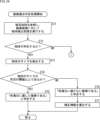
- step S15 the determination unit 22 acquires the synchronized captured image, depth image, and turbidity from the storage unit 17, and executes an image compatibility determination process using the acquired captured image, depth image, and turbidity. Details of the image compatibility determination process will be described later with reference to the flowchart in FIG. 8, but the image compatibility determination process determines whether or not the captured image is suitable for color restoration. If the captured image is not suitable for color restoration, correction information is also calculated.
- step S16 the determination unit 22 determines whether the result of the image compatibility determination process is an image suitable for color restoration. If it is determined in step S16 that the image is suitable for color restoration, the process proceeds to step S17.
- step S17 the determination unit 22 displays the captured image on the display 18. The determination unit 22 also stores the determination result in the storage unit 17 in association with the corresponding captured image (R) and depth and turbidity data. A display indicating that the image is suitable for color restoration may be superimposed on the captured image displayed on the display 18. The user moves to the next imaging position according to the imaging plan.
- step S16 determines whether the image is suitable for color restoration. If it is determined in step S16 that the image is not suitable for color restoration, the process proceeds to step S18, and the determination unit 22 displays the captured image and the correction information together with the determination result on the display 18.
- the determination unit 22 also stores the determination result in the storage unit 17 in association with the corresponding captured image (R) and depth and turbidity data. The user moves the imaging position according to the correction information displayed on the display 18.
- step S19 the imaging device 1 determines whether to end imaging. When imaging data corresponding to all imaging positions in the imaging plan has been stored in the storage unit 17, it is determined that imaging is to end. If it is determined in step S19 that imaging has not yet ended, the process returns to step S11, and the above-mentioned steps S11 to S19 are repeated. On the other hand, if it is determined in step S19 that imaging has ended, the imaging process in FIG. 7 ends.
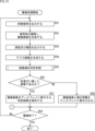
- step S15 in FIG. 7 The details of the image compatibility determination process in step S15 in FIG. 7 will be described with reference to the flowchart in FIG. 8.
- step S31 the determination unit 22 executes a predetermined object detection process on the captured image acquired from the storage unit 17. For example, by semantic segmentation, as described with reference to FIG. 2, pixels that show water as a subject are distinguished from pixels that show an object. Note that any object detection process may be adopted, not limited to semantic segmentation, and detected objects may be identified by bounding boxes, etc.
- step S32 the determination unit 22 determines whether an object is present in the captured image based on the object detection processing result. If it is determined in step S32 that an object is not present, the process proceeds to step S19 in FIG. 7. On the other hand, if it is determined in step S32 that an object is present, the process proceeds to step S33, where the distance to the detected object is calculated. Specifically, the determination unit 22 calculates the distance to the detected object by calculating a representative value of the distance on a segment-by-segment basis using the results of semantic segmentation and the depth image.
- step S34 the determination unit 22 determines whether the distance of the detected object is within the appropriate distance range. If it is determined in step S34 that the distance of the detected object is within the appropriate distance range, the process proceeds to step S35, and the determination unit 22 determines that the captured image is an image suitable for color restoration.
- step S34 determines that the distance of the detected object is not within the appropriate distance range.
- step S37 the determination unit 22 calculates correction information for moving the imaging position so that the subject is captured at a distance suitable for color restoration.
- step S35 or step S37 the process returns to the flowchart in FIG. 7 and proceeds to step S16.
- the imaging sensors 11R and 11L capture an image of an underwater subject and generate an image.
- the determination unit 22 acquires an image captured by the imaging sensor 11R or 11L (e.g., image (R)).
- the determination unit 22 also acquires a depth image, which is distance information generated from the two captured images (R) and (L) captured by the imaging sensors 11R and 11L, as auxiliary information to assist in the determination.
- the determination unit 22 executes an image compatibility determination process using the acquired captured image and depth image to determine whether the captured image is suitable for color restoration or not, and outputs correction information for changing the relative position of the imaging device 1 with respect to the subject according to the determination result.
- the user can change the imaging position of the imaging device 1 according to the correction information and capture again. This makes it possible to acquire (capture) an image suitable for color restoration in underwater imaging. It is possible to perform imaging of multiple points continuously based on an imaging plan, as well as imaging of one point.
- the captured image, depth image, and turbidity data are temporarily stored in the memory unit 17, and the determination unit 22 acquires the data stored in the memory unit 17 and performs image compatibility determination processing. However, if the processing speed is sufficient, the determination unit 22 may acquire data without going through the memory unit 17 and perform image compatibility determination processing. Regarding the depth and turbidity data, if it is not necessary to strictly synchronize it with the captured image, the supply of a synchronization signal to the depth meter 14 and turbidity meter 15 may be omitted.
- the image captured by the imaging device 1 is stored in the storage unit 17, regardless of whether color restoration is appropriate or not.
- FIG. 9 shows an example of the configuration of the storage unit 17 when storing an image captured by the imaging device 1 regardless of whether color restoration is appropriate or not.
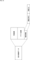
- the storage unit 17 has at least one data storage area 101, which is used for both display and data storage. As shown in the state transition diagram on the right, imaging data such as the captured image generated each time imaging is performed is stored in the data storage area 101.
- FIG. 10 shows an example of the data structure of imaging data stored in the data storage area 101 after one imaging session.
- the imaging data obtained from one capture is composed of the captured image (RGB image), a depth image, and auxiliary information.
- the auxiliary information is composed of depth, turbidity, and suitability/unsuitability information that indicates whether the image is suitable for color restoration with "1" (suitable) or "0" (unsuitable).
- captured images that are not suitable for color restoration may not be stored in the memory unit 17.
- FIG. 11 shows an example of the configuration of the storage unit 17 when storing only captured images suitable for color restoration.
- the storage unit 17 has a data holding area 111 for display and a data holding area 112 for external output.
- the data holding area 111 for display is configured as a ring buffer.
- imaging data such as the generated captured image is stored in the data holding area 111 configured as a ring buffer for each imaging session.
- the imaging data to be saved is stored in the data holding area 112 for external output.
- the storage control state returns to a state in which the imaging data such as the generated captured image is stored in the data holding area 111 configured as a ring buffer.
- Figure 12 shows an example of the data structure of imaging data when only captured images suitable for color restoration are stored.
- the imaging data obtained from one capture consists of the captured image (RGB image), a depth image, and auxiliary information.
- the auxiliary information consists of depth and turbidity. Only captured images suitable for color restoration are stored, so suitable/unsuitable information is not required.
- the captured image (RGB image) of the subject, the depth image as auxiliary information, and the depth and turbidity data at the time of capture are stored in the storage unit 17 as captured image data. If captured images unsuitable for color restoration are also stored, appropriate/unsuitable information indicating whether the image is suitable for color restoration is added as auxiliary information and stored in the storage unit 17.
- the captured image data stored in the storage unit 17 is output to, for example, the 3D reconstruction processing device 2.
- the auxiliary information can be used for color restoration when performing 3D reconstruction processing.
- the depth data can be used to estimate how much light of each color remains, and the turbidity data can be used to estimate the amount of blue attenuation.
- the depth and turbidity data which are auxiliary information, may be stored as part of the image data as metadata of the captured image or depth image.
- the imaging device 1 does not need to have a reference object such as a calibration device, as in the technology of Patent Document 1 described in the background art, and can therefore more easily provide captured images suitable for color restoration.
- FIG. 13 is a block diagram showing an example configuration of a second embodiment of an imaging device to which the technology of the present disclosure is applied.
- the display 18 is configured to be separate from the device body of the imaging device 1B.
- the display 18 can adjust the distance from the imaging device 1B to be expandable or contractible, and can adjust the angle (direction) relative to the imaging device 1B.
- the display 18 may be configured to be detachable from the body of the imaging device 1B.
- the configuration of the imaging device 1B other than the display 18 is the same as in the first embodiment.
- FIG. 14 shows imaging positions P1, P2, and P3 in that order, similar to the imaging plan described in FIG. 4 to FIG. 6.
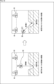
- a in FIG. 14 shows a state in which, when imaging is performed using the imaging device 1 of the first embodiment, the distance d to the subject at imaging position P2 is not included in the suitable distance range RG_OK, and the captured image is determined to be unsuitable for color restoration.
- the display 18 is configured as one unit with the device body, so the user (photographer) needs to move together with the imaging device 1 to keep the distance to the subject within an appropriate range, as shown in B of Figure 14.
- the display 18 is configured separately from the device body, so as shown in FIG. 14C, it is only necessary to move the position of the imaging device 1B and not change the user position.
- FIG. 14 shows how the position of the imaging device 1B is changed in a direction that shortens the distance from the subject to the imaging device 1B, but it is of course also possible to change the position of the imaging device 1B in a direction that moves it away.
- the imaging device 1B can move so that the distance d to the subject is within the optimum distance range RG_OK, but the imaging device 1B will not be directly facing the subject (e.g., the ground surface) that is tilted when capturing an image.
- the attitude of imaging device 1B can also be controlled to change so that imaging device 1B faces the subject directly.
- the attitude of imaging device 1B can be changed so that it faces the subject directly, without changing the user position.
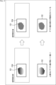
- FIG. 17 is a schematic diagram of a mask image 152 in which the depth value of only object 151, which is a subject included in the FOV of the image capture device 1, is extracted before and after posture correction is performed so that the subject is directly facing the object 151.
- the depth value becomes higher (closer to white) as you move toward the top of the image, meaning the distance becomes farther.
- the slope of the depth value is reduced.
- the imaging device 1B If the imaging device 1B is tilted with respect to the subject, the way colors appear will change, so it is desirable to capture the subject while facing it directly. By displaying information that changes the attitude of the imaging device 1B with respect to the subject as correction information, it is possible to obtain a captured image suitable for color restoration.
- the detailed tilt angle ⁇ of the subject may be calculated using the depth value of the depth image and the posture may be changed, but it may also be possible to simply determine whether image capture device 1B is significantly tilted relative to the subject and then change the tilt of image capture device 1B by a fixed tilt angle ⁇ 0 to correct the extreme tilt.
- FIGS. 18 and 19 are diagrams explaining the simple tilt determination process, which determines the tilt relative to the subject in a simple manner and controls the posture.
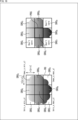
- the determination unit 22 calculates a rectangular region RG circumscribing the segment SG, and divides the rectangular region RG surrounding the subject region into a plurality of regions SRG (hereinafter referred to as divided regions SRG).
- the rectangular region RG is composed of a region connected by four points of coordinates (min_x, min_y), (max_x, min_y), (min_x, max_y), and (max_x, max_y), and the rectangular region RG is divided into nine divided regions SRG1 to SRG9 of 3x3.
- the number of pixels in the vertical direction of one divided region SRG is v [pix], and the number of pixels in the horizontal direction is h [pix].
- the representative value DP i can be calculated using a median, an average value, a mode, or the like, as in the case of the representative value of the object 53 described above.
- the determination unit 22 also determines a reference divided region PRG, which is a divided region SRG that serves as a reference for tilt determination, from among the plurality of divided regions SRG i . For example, the divided region SRG 5 located in the center of the rectangular region RG is determined as the reference divided region PRG.
- the determination unit 22 classifies each divided region SRGj into one of the following, depending on the distance difference DIF_DPj : a distance farther than the reference divided region PRG ("0"), a distance similar to the reference divided region PRG ("1"), or a distance closer than the reference divided region PRG ("2"), using the following determination formula (1). Note that the reference divided region PRG is "1".
- each divided region SRG i in FIG. 18 are, for example, as shown in FIG. 19, with divided regions SRG 2 and SRG 3 being "0", divided regions SRG 4 to SRG 6 being "1", and divided region SRG 8 being "2".
- the determination unit 22 determines by pattern matching which of a plurality of pre-stored registered patterns PT1 , PT2 , PT3 , PT4 , ... the pattern of the classified segment SG matches.
- the determination unit 22 corrects extreme tilt by generating correction information that changes the tilt direction corresponding to the matching registered pattern PT by a fixed tilt angle ⁇ 0 . Don't care regions are ignored in the pattern matching. Furthermore, if the pattern does not match any of the plurality of pre-stored registered patterns PT, no correction information is generated.
- the imaging device 1B divides the subject area into a plurality of divided areas SRG, calculates the distance (representative value DP i ) for each divided area SRG, determines a pattern by comparing with the reference divided area PRG, and detects the attitude of the imaging device 1B with respect to the subject using pattern matching. Then, by outputting correction information for changing the fixed tilt angle ⁇ 0 according to the detected attitude, the imaging device 1B can be controlled so as to face the subject directly.
- the user can change the attitude of the imaging device 1 according to the correction information and capture the image again. This makes it possible to obtain (capture) an image suitable for color restoration when capturing images underwater.
- FIG. 20 is a block diagram showing an example configuration of a third embodiment of an imaging device to which the technology of the present disclosure is applied.
- the imaging device 1C of the third embodiment differs from the first embodiment in that the number of imaging sensors 11 is changed to one and a distance measurement sensor 201 is newly added, but otherwise is configured in the same way as the first embodiment.
- the imaging device 1 of the first embodiment uses one of the two captured images (R) and (L) captured by the two imaging sensors 11 as an image for data storage, and uses a depth image generated from the two captured images (R) and (L) to determine whether the subject has been captured at a distance suitable for color restoration.
- the imaging device 1C of the third embodiment uses an image captured by a single imaging sensor 11 as an image for data storage and display, and uses a depth image output by the distance measurement sensor 201 to determine whether the subject has been captured at a distance suitable for color restoration.
- the distance sensor 201 has a light source that outputs infrared light or the like as active light, and is a sensor that measures the distance to a specified object that is a subject by using an indirect ToF (Time of Flight) method or a direct ToF method.
- the indirect ToF method is a method that calculates the distance to an object by irradiating a surrounding object with irradiation light, detecting the reflected light that is reflected by the surface of the object and returning, and detecting the flight time from when the irradiation light is irradiated to when the reflected light is received as a phase difference, thereby realizing highly accurate measurement of a relatively short distance range.
- the direct ToF method is a method that calculates the distance to an object by directly measuring the flight time from when the irradiation light is emitted to when the reflected light is received, and is more effective at measuring long distances than the indirect ToF method.
- the distance sensor 201 measures the distance to a specified object that is a subject based on the received reflected light, generates a depth image, and supplies it to the preprocessing unit 21.
- the depth image was generated from the stereo camera image, so there was a one-to-one correspondence between the pixels of the captured image and the depth image, but the distance measurement sensor 201 and the image sensor 11 may have different numbers of pixels.
- the pixels of the captured image and the depth image are associated in advance, so that the distance of the subject shown in the captured image can be detected.
- the captured image and the depth image are similarly synchronized by a synchronization signal from the timing generator 12. Since the distance measurement sensor 201 generates a depth image and supplies it to the pre-processing unit 21, there is no need for the pre-processing unit 21 to generate a depth image.
- FIG. 21 is a flowchart of the imaging process performed by the imaging device 1C of the third embodiment.
- Steps S51 to S59 in the imaging process of FIG. 21 correspond to steps S11 to S19 in the imaging process of FIG. 7, respectively, and are performed in the same manner as the imaging process of FIG. 7, except that steps S52 and S54 have been changed.
- step S52 in the first embodiment, the two image sensors 11R and 11L capture images of the subject in accordance with a synchronization signal and generate two captured images, but in the third embodiment, one image sensor 11 captures images of the subject in accordance with a synchronization signal and generates a captured image.
- step S54 in the first embodiment, the pre-processing unit 21 generates a depth image as pre-processing, but in the third embodiment, the distance measurement sensor 201 generates a depth image and supplies it to the pre-processing unit 21.
- the pre-processing unit 21 supplies the captured image and depth image provided to the storage unit 17.
- the pre-processing unit 21 may perform noise reduction processing, etc., as necessary.
- the imaging device 1C acquires distance information to the subject as auxiliary information from an underwater image of the subject captured by one imaging sensor 11 and a depth image captured by the distance measurement sensor 201. The imaging device 1C then uses the captured image and the distance information to the subject to determine whether the captured image is suitable for color restoration.
- the pre-processing unit 21 does not need to generate a depth image from two captured images, which reduces the processing load on the image processing unit 16.
- the user can change the imaging position of the imaging device 1C according to the correction information and capture the image again. This makes it possible to obtain (capture) an image suitable for color restoration when capturing images underwater.
- FIG. 22 is a block diagram showing an example configuration of a fourth embodiment of an imaging device to which the technology of the present disclosure is applied.
- the imaging device 1D of the fourth embodiment differs from the first embodiment in that the number of imaging sensors 11 is changed to one and a sonar 221 is newly added, but otherwise is configured in the same way as the first embodiment.
- the imaging device 1D of the fourth embodiment uses an image captured by a single imaging sensor 11 as an image for data storage and display, and uses a depth image output by the sonar 221 to determine whether the subject has been captured at a distance suitable for color restoration.
- Sonar 221 is a device that emits sound waves underwater and measures the distance to an object based on the time it takes for the sound waves to reflect off the object and return. Sonar 221 measures the distance to a specific object based on the received sound waves, generates a depth image, and supplies it to pre-processing unit 21.
- the depth image was generated from the stereo camera image, so there was a one-to-one correspondence between the pixels of the captured image and the depth image, but the number of pixels of the depth image generated by sonar 221 and the captured image may differ.
- the pixels of the captured image and the depth image are matched in advance, making it possible to detect the distance to the subject shown in the captured image.
- the captured image and the depth image are synchronized by a synchronization signal from timing generator 12.
- the imaging process of the imaging device 1D of the fourth embodiment is basically the same as the imaging process of the third embodiment described with reference to FIG. 21, so a description thereof will be omitted.
- the imaging device 1D acquires distance information to the subject as auxiliary information from an underwater image of the subject captured by one imaging sensor 11 and a depth image captured by the sonar 221. The imaging device 1D then uses the captured image and the distance information to the subject to determine whether the captured image is suitable for color restoration.
- the pre-processing unit 21 does not need to process a depth image from two captured images, which reduces the processing load on the image processing unit 16.
- the user can change the imaging position of the imaging device 1D according to the correction information and capture the image again. This makes it possible to obtain (capture) an image suitable for color restoration when capturing images underwater.
- FIG. 23 is a block diagram showing an example configuration of a fifth embodiment of an imaging device to which the technology of the present disclosure is applied.
- the imaging device 1E of the fifth embodiment the number of imaging sensors 11 is changed to one, and the timing generator 12 is omitted. On the other hand, a subject DB 241 is newly added. In other respects, the imaging device 1E is configured in the same way as in the first embodiment.
- the imaging device 1E does not have a means for measuring the distance to the subject, and uses only the captured image captured by the imaging sensor 11 to determine whether the subject has been captured at a distance suitable for color restoration.
- the subject DB 241 stores a large number of template images for the object to be captured.
- the determination unit 22 refers to the template images in the subject DB 241 and determines whether a known object is present in the captured image acquired via the storage unit 17. If a known object registered in the subject DB 241 is detected, the determination unit 22 detects the size of the object using a bounding box or the like, and determines whether the captured image is suitable for color restoration based on the detected size.
- the determination unit 22 determines that the object has been captured at a sufficiently close distance and that the image is suitable for color restoration. On the other hand, if the size of the detected object is smaller than the predetermined threshold, the determination unit 22 determines that the image is not suitable for color restoration.
- a depth image is not generated, and therefore the imaging data output to an external device does not include a depth image.
- the timing generator 12 is omitted because there is no need to strictly synchronize the depth and turbidity with the captured image, but a timing generator 12 may be provided as in the above-described embodiment to synchronize the captured image with the depth and turbidity.
- steps S11 and S14 in the imaging process of FIG. 7 are omitted.
- step S12 a subject is imaged by one imaging sensor 11, and an image is generated. The generated image is supplied to the storage unit 17 via the pre-processing unit 21.
- step S13 the depth meter 14 and the turbidity meter 15 each measure the depth and turbidity, and output them to the storage unit 17.
- step S15 the determination unit 22 executes an image compatibility determination process using the image stored in the storage unit 17. Steps S16 to S19 are similar, and are therefore omitted.
- FIG. 24 is a detailed flowchart of the image compatibility determination process in step S15 of FIG. 7 in the fifth embodiment.
- step S71 the determination unit 22 refers to a template image in the subject DB 241 and performs object detection processing on the captured image.
- step S72 the determination unit 22 determines whether an object is present in the captured image. If it is determined in step S72 that an object is not present, the process proceeds to step S19 in FIG. 7. On the other hand, if it is determined in step S72 that an object is present, the process proceeds to step S73, where the determination unit 22 detects the size of the object using a bounding box or the like.
- step S74 the determination unit 22 determines whether the size of the detected object is equal to or larger than a predetermined threshold. If it is determined in step S74 that the size of the detected object is equal to or larger than the predetermined threshold, the process proceeds to step S75, and the determination unit 22 determines that the captured image is suitable for color restoration.
- step S74 determines that the size of the detected object is smaller than the predetermined threshold.
- step S77 the determination unit 22 calculates correction information for moving the imaging position so that the subject is captured at a distance suitable for color restoration, more specifically, correction information for moving the imaging position so as to get closer to the subject.
- step S75 or step S77 the process returns to the flowchart in FIG. 7 and proceeds to step S16.
- the imaging device 1E obtains the size of the subject (object size) from an image of an underwater subject captured by one imaging sensor 11, and determines whether the captured image is suitable for color restoration based on the size of the subject.
- the user can change the imaging position of the imaging device 1E according to the correction information and capture the image again. This makes it possible to obtain (capture) an image suitable for color restoration when capturing images underwater.
- Example of computer configuration The series of processes performed by the image processing unit 16 described above can be executed by hardware or software.
- the programs constituting the software are installed in a computer.
- the computer includes a microcomputer incorporated in dedicated hardware, and a general-purpose personal computer, for example, capable of executing various functions by installing various programs.
- FIG. 25 is a block diagram showing an example of the hardware configuration of a computer that executes the above-mentioned series of processes using a program.
- a CPU Central Processing Unit
- ROM Read Only Memory
- RAM Random Access Memory
- an input/output interface 305 Further connected to the bus 304 is an input/output interface 305. Connected to the input/output interface 305 are an input unit 306, an output unit 307, a storage unit 308, a communication unit 309, and a drive 310.
- the input unit 306 includes a keyboard, mouse, microphone, touch panel, input terminal, etc.
- the output unit 307 includes a display, speaker, output terminal, etc.
- the storage unit 308 includes a hard disk, SSD (Solid State Drive), RAM disk, non-volatile memory, etc.
- the communication unit 309 includes a network interface, etc.
- the drive 310 drives a removable recording medium 311 such as a magnetic disk, optical disk, magneto-optical disk, or semiconductor memory.
- the CPU 301 loads a program stored in the storage unit 308, for example, into the RAM 303 via the input/output interface 305 and the bus 304, and executes the program, thereby carrying out the above-mentioned series of processes.
- the RAM 303 also stores data necessary for the CPU 301 to execute various processes, as appropriate.
- the program executed by the computer (CPU 301) can be provided by being recorded on a removable recording medium 311, such as a package medium, for example.
- the program can also be provided via a wired or wireless transmission medium, such as a local area network, the Internet, or digital satellite broadcasting.
- a program can be installed in the storage unit 308 via the input/output interface 305 by inserting the removable recording medium 311 into the drive 310.
- the program can also be received by the communication unit 309 via a wired or wireless transmission medium and installed in the storage unit 308.
- the program can be pre-installed in the ROM 302 or storage unit 308.
- a system refers to a collection of multiple components (devices, modules (parts), etc.), regardless of whether all the components are in the same housing. Therefore, multiple devices housed in separate housings and connected via a network, and a single device in which multiple modules are housed in a single housing, are both systems.
- the technology disclosed herein can be configured as cloud computing, in which a single function is shared and processed collaboratively by multiple devices over a network.
- each step described in the above flowchart can be executed by one device, or can be shared and executed by multiple devices.
- the multiple processes included in that one step can be executed by one device, or can be shared and executed by multiple devices.
- the technology of the present disclosure can have the following configurations.
- the imaging device acquiring an image of an underwater subject captured by at least one imaging sensor; determining whether the captured image is an image suitable for color restoration, and outputting correction information for changing a relative position with respect to the subject in accordance with a result of the determination.
- the imaging method according to (1) further comprising: determining whether the captured image is suitable for color restoration using the captured image and the auxiliary information.
- the auxiliary information is a depth image including distance information of the subject, the depth image being calculated from two captured images obtained by capturing images of the subject underwater using two image sensors;
- the imaging method according to (2) further comprising: determining whether the captured image is suitable for color restoration using the captured image and the depth image.
- the auxiliary information is a depth image including distance information of the subject obtained by a distance measuring sensor;
- the imaging method according to (2) further comprising: determining whether the captured image is suitable for color restoration using the captured image and the depth image.
- the auxiliary information is a depth image obtained by sonar and including distance information of the subject, and the captured image and the depth image are used to determine whether the captured image is suitable for color restoration. The imaging method described in (2).
- the imaging method according to (1) further comprising determining whether the captured image is suitable for color restoration based on a size of the subject.
- the predetermined distance range is a range from a shortest focal length to a shortest focal length plus a predetermined additional value.
- the imaging method according to (8), wherein the predetermined additional value is changed depending on turbidity in water.
- At least one image sensor that captures an image of an underwater subject and outputs a captured image; a determination unit that determines whether the captured image is an image suitable for color restoration, and outputs correction information for changing a relative position with respect to the subject according to a determination result.
- On the computer acquiring an image of an underwater subject captured by at least one imaging sensor; a program for executing a process of determining whether the captured image is an image suitable for color restoration, and outputting correction information for changing a relative position with respect to the subject depending on a result of the determination.
Landscapes
- Engineering & Computer Science (AREA)
- Physics & Mathematics (AREA)
- Multimedia (AREA)
- Signal Processing (AREA)
- Acoustics & Sound (AREA)
- Mechanical Engineering (AREA)
- Ocean & Marine Engineering (AREA)
- General Physics & Mathematics (AREA)
- Studio Devices (AREA)
Priority Applications (1)
| Application Number | Priority Date | Filing Date | Title |
|---|---|---|---|
| JP2025503754A JPWO2024181135A1 (https=) | 2023-02-27 | 2024-02-15 |
Applications Claiming Priority (2)
| Application Number | Priority Date | Filing Date | Title |
|---|---|---|---|
| JP2023028390 | 2023-02-27 | ||
| JP2023-028390 | 2023-02-27 |
Publications (1)
| Publication Number | Publication Date |
|---|---|
| WO2024181135A1 true WO2024181135A1 (ja) | 2024-09-06 |
Family
ID=92589729
Family Applications (1)
| Application Number | Title | Priority Date | Filing Date |
|---|---|---|---|
| PCT/JP2024/005158 Ceased WO2024181135A1 (ja) | 2023-02-27 | 2024-02-15 | 撮像方法、撮像装置、及び、プログラム |
Country Status (2)
| Country | Link |
|---|---|
| JP (1) | JPWO2024181135A1 (https=) |
| WO (1) | WO2024181135A1 (https=) |
Citations (3)
| Publication number | Priority date | Publication date | Assignee | Title |
|---|---|---|---|---|
| JP2011205619A (ja) * | 2010-01-29 | 2011-10-13 | Shinsedai Kk | 画像処理装置、画像処理方法、コンピュータプログラム、及び、電子機器 |
| JP2014202922A (ja) * | 2013-04-05 | 2014-10-27 | キヤノン株式会社 | 撮像装置およびその制御方法 |
| WO2017208288A1 (ja) * | 2016-05-30 | 2017-12-07 | パナソニックIpマネジメント株式会社 | 水陸判定装置、水陸判定方法及び水中検査装置 |
-
2024
- 2024-02-15 JP JP2025503754A patent/JPWO2024181135A1/ja active Pending
- 2024-02-15 WO PCT/JP2024/005158 patent/WO2024181135A1/ja not_active Ceased
Patent Citations (3)
| Publication number | Priority date | Publication date | Assignee | Title |
|---|---|---|---|---|
| JP2011205619A (ja) * | 2010-01-29 | 2011-10-13 | Shinsedai Kk | 画像処理装置、画像処理方法、コンピュータプログラム、及び、電子機器 |
| JP2014202922A (ja) * | 2013-04-05 | 2014-10-27 | キヤノン株式会社 | 撮像装置およびその制御方法 |
| WO2017208288A1 (ja) * | 2016-05-30 | 2017-12-07 | パナソニックIpマネジメント株式会社 | 水陸判定装置、水陸判定方法及び水中検査装置 |
Also Published As
| Publication number | Publication date |
|---|---|
| JPWO2024181135A1 (https=) | 2024-09-06 |
Similar Documents
| Publication | Publication Date | Title |
|---|---|---|
| US9392262B2 (en) | System and method for 3D reconstruction using multiple multi-channel cameras | |
| CN111480342B (zh) | 编码装置、编码方法、解码装置、解码方法和存储介质 | |
| US20130335535A1 (en) | Digital 3d camera using periodic illumination | |
| CN110799918A (zh) | 车辆用的方法、设备和计算机程序 | |
| JP5419757B2 (ja) | 顔画像合成装置 | |
| US12165272B2 (en) | Image processing apparatus, image processing method, and storage medium for generating composite image using 2D image and 3DCG | |
| WO2014064870A1 (ja) | 画像処理装置および画像処理方法 | |
| JP2010050540A (ja) | 投写型表示装置および表示方法 | |
| JP2010050542A (ja) | 投写型表示装置および表示方法 | |
| JP2017045283A (ja) | 情報処理装置および情報処理方法 | |
| US20130039568A1 (en) | Image processing apparatus, image processing method, and recording medium | |
| US20240388787A1 (en) | Information processing device, video processing method, and program | |
| US11030732B2 (en) | Information processing device, information processing system, and image processing method for generating a sum picture by adding pixel values of multiple pictures | |
| EP3832601A1 (en) | Image processing device and three-dimensional measuring system | |
| WO2022054422A1 (ja) | 障害物検知装置、障害物検知システム及び障害物検知方法 | |
| JP2018195241A (ja) | 情報処理装置、情報処理方法、及びプログラム | |
| JP2016075658A (ja) | 情報処理システムおよび情報処理方法 | |
| JP2013025649A (ja) | 画像処理装置及び画像処理方法、プログラム | |
| US20220254035A1 (en) | Image processing apparatus, head-mounted display, and method for acquiring space information | |
| US10497141B2 (en) | Three-dimensional imaging using frequency domain-based processing | |
| CN111724470A (zh) | 一种处理方法及电子设备 | |
| JP2004133919A (ja) | 擬似3次元画像生成装置および生成方法並びにそのためのプログラムおよび記録媒体 | |
| US20130271572A1 (en) | Electronic device and method for creating three-dimentional image | |
| WO2024181135A1 (ja) | 撮像方法、撮像装置、及び、プログラム | |
| JP4741019B2 (ja) | インターホン装置 |
Legal Events
| Date | Code | Title | Description |
|---|---|---|---|
| 121 | Ep: the epo has been informed by wipo that ep was designated in this application |
Ref document number: 24763618 Country of ref document: EP Kind code of ref document: A1 |
|
| ENP | Entry into the national phase |
Ref document number: 2025503754 Country of ref document: JP Kind code of ref document: A |
|
| WWE | Wipo information: entry into national phase |
Ref document number: 2025503754 Country of ref document: JP |
|
| NENP | Non-entry into the national phase |
Ref country code: DE |
|
| 122 | Ep: pct application non-entry in european phase |
Ref document number: 24763618 Country of ref document: EP Kind code of ref document: A1 |