WO2024181051A1 - 円筒形電池 - Google Patents
円筒形電池 Download PDFInfo
- Publication number
- WO2024181051A1 WO2024181051A1 PCT/JP2024/003825 JP2024003825W WO2024181051A1 WO 2024181051 A1 WO2024181051 A1 WO 2024181051A1 JP 2024003825 W JP2024003825 W JP 2024003825W WO 2024181051 A1 WO2024181051 A1 WO 2024181051A1
- Authority
- WO
- WIPO (PCT)
- Prior art keywords
- negative electrode
- winding
- positive electrode
- tape
- cylindrical battery
- Prior art date
- Legal status (The legal status is an assumption and is not a legal conclusion. Google has not performed a legal analysis and makes no representation as to the accuracy of the status listed.)
- Ceased
Links
Images



Classifications
-
- H—ELECTRICITY
- H01—ELECTRIC ELEMENTS
- H01M—PROCESSES OR MEANS, e.g. BATTERIES, FOR THE DIRECT CONVERSION OF CHEMICAL ENERGY INTO ELECTRICAL ENERGY
- H01M10/00—Secondary cells; Manufacture thereof
- H01M10/04—Construction or manufacture in general
-
- H—ELECTRICITY
- H01—ELECTRIC ELEMENTS
- H01M—PROCESSES OR MEANS, e.g. BATTERIES, FOR THE DIRECT CONVERSION OF CHEMICAL ENERGY INTO ELECTRICAL ENERGY
- H01M10/00—Secondary cells; Manufacture thereof
- H01M10/05—Accumulators with non-aqueous electrolyte
- H01M10/052—Li-accumulators
-
- H—ELECTRICITY
- H01—ELECTRIC ELEMENTS
- H01M—PROCESSES OR MEANS, e.g. BATTERIES, FOR THE DIRECT CONVERSION OF CHEMICAL ENERGY INTO ELECTRICAL ENERGY
- H01M10/00—Secondary cells; Manufacture thereof
- H01M10/05—Accumulators with non-aqueous electrolyte
- H01M10/058—Construction or manufacture
- H01M10/0587—Construction or manufacture of accumulators having only wound construction elements, i.e. wound positive electrodes, wound negative electrodes and wound separators
-
- Y—GENERAL TAGGING OF NEW TECHNOLOGICAL DEVELOPMENTS; GENERAL TAGGING OF CROSS-SECTIONAL TECHNOLOGIES SPANNING OVER SEVERAL SECTIONS OF THE IPC; TECHNICAL SUBJECTS COVERED BY FORMER USPC CROSS-REFERENCE ART COLLECTIONS [XRACs] AND DIGESTS
- Y02—TECHNOLOGIES OR APPLICATIONS FOR MITIGATION OR ADAPTATION AGAINST CLIMATE CHANGE
- Y02E—REDUCTION OF GREENHOUSE GAS [GHG] EMISSIONS, RELATED TO ENERGY GENERATION, TRANSMISSION OR DISTRIBUTION
- Y02E60/00—Enabling technologies; Technologies with a potential or indirect contribution to GHG emissions mitigation
- Y02E60/10—Energy storage using batteries
-
- Y—GENERAL TAGGING OF NEW TECHNOLOGICAL DEVELOPMENTS; GENERAL TAGGING OF CROSS-SECTIONAL TECHNOLOGIES SPANNING OVER SEVERAL SECTIONS OF THE IPC; TECHNICAL SUBJECTS COVERED BY FORMER USPC CROSS-REFERENCE ART COLLECTIONS [XRACs] AND DIGESTS
- Y02—TECHNOLOGIES OR APPLICATIONS FOR MITIGATION OR ADAPTATION AGAINST CLIMATE CHANGE
- Y02P—CLIMATE CHANGE MITIGATION TECHNOLOGIES IN THE PRODUCTION OR PROCESSING OF GOODS
- Y02P70/00—Climate change mitigation technologies in the production process for final industrial or consumer products
- Y02P70/50—Manufacturing or production processes characterised by the final manufactured product
Definitions
- This disclosure relates to cylindrical batteries.
- Cylindrical batteries are equipped with a wound electrode body in which a positive electrode and a negative electrode are wound in a spiral shape with a separator between them.
- the positive electrode and negative electrode expand and contract, which may cause plate deformation in which at least one of the positive electrode and negative electrode is locally deformed.
- Patent Document 1 discloses a cylindrical battery equipped with a wound electrode body having an insulating tape attached to the negative electrode so as to straddle the surface of the negative electrode lead in the winding direction in order to suppress deformation of the joint of the negative electrode lead.
- the winding start end of the positive electrode forms a step along the winding direction, and the negative electrode portion that faces the inside of the winding start end of the positive electrode may deform during charge and discharge cycles. If this deformation of the negative electrode portion occurs, the distance between the positive and negative electrodes may vary, causing uneven charge and discharge reactions and deteriorating cycle characteristics.
- Patent Document 1 may not be able to sufficiently suppress the deformation of the negative electrode portion that faces the inside of the winding start end of the positive electrode, which causes the step described above.
- Patent Document 1 raises concerns that the capacity of the cylindrical battery may decrease due to the insulating tape being attached to the negative electrode.
- the present disclosure therefore aims to provide a cylindrical battery that can suppress deformation of the negative electrode portion that faces the winding start end of the positive electrode that occurs during charge and discharge cycles.
- the cylindrical battery disclosed herein is a cylindrical battery having an electrode assembly in which a positive electrode and a negative electrode including a core and a mixture layer are spirally wound with a separator interposed therebetween, and the negative electrode is characterized in that it has a tape attached to the inner surface of the winding so as to straddle in the winding direction a first opposing position that faces the inner side of the winding start end of the positive electrode.
- the cylindrical battery disclosed herein can suppress deformation of the negative electrode portion that faces the winding start end of the positive electrode during charge and discharge cycles.
- FIG. 2 is an axial cross-sectional view of a cylindrical battery according to an embodiment of the present invention.
- 4 is a schematic diagram showing a radial cross section of the winding start side of the electrode body.
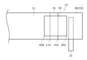
- FIG. FIG. 2 is a schematic diagram showing the winding start side of the electrode body in a developed state.
- FIG. 4 is a schematic diagram showing a radial cross section of FIG. 3 .
- the cylindrical battery 10 has a positive electrode 11, a negative electrode 12, and a separator 13, and is equipped with an electrode body 14 in which the positive electrode 11 and the negative electrode 12 are wound with the separator 13 interposed therebetween.
- the cylindrical battery 10 also has a cylindrical outer can 16 with a bottom that houses the electrode body 14, and a sealing body 17 that closes the opening of the outer can 16.
- the outer can 16 houses an electrolyte together with the electrode body 14.
- the outer can 16 has a grooved portion 22 formed in its side wall, and the sealing body 17 is supported by the grooved portion 22 to close the opening of the outer can 16.
- the sealing body 17 side of the cylindrical battery 10 will be referred to as the top, and the bottom side of the outer can 16 will be referred to as the bottom.
- the negative electrode 12 includes a negative electrode core 40 and a negative electrode mixture layer 41, and has a tape 50 attached to the inner surface of the winding so as to straddle in the winding direction a first opposing position 12A that faces the winding start end 11A of the positive electrode 11.
- the tape 50 can suppress deformation of the part of the negative electrode 12 that faces the inner surface of the winding start end of the positive electrode 11 due to charge and discharge cycles.
- the electrolyte may be an aqueous electrolyte, but in this embodiment, a non-aqueous electrolyte is used.
- the non-aqueous electrolyte has lithium ion conductivity.
- the non-aqueous electrolyte may be a liquid electrolyte (electrolytic solution) or a solid electrolyte.
- the cylindrical battery 10 is, for example, a non-aqueous electrolyte secondary battery, and is preferably a lithium ion battery.
- the liquid electrolyte includes a non-aqueous solvent and an electrolyte salt dissolved in the non-aqueous solvent.
- a non-aqueous solvent for example, esters, ethers, nitriles, amides, and mixed solvents of two or more of these are used as the non-aqueous solvent.
- the non-aqueous solvent include ethylene carbonate (EC), ethyl methyl carbonate (EMC), dimethyl carbonate (DMC), diethyl carbonate (DEC), and mixed solvents of these.
- the non-aqueous solvent may contain a halogen-substituted product (e.g., fluoroethylene carbonate, etc.) in which at least a part of the hydrogen of these solvents is replaced with a halogen atom such as fluorine.
- a halogen-substituted product e.g., fluoroethylene carbonate, etc.
- a lithium salt such as LiPF6 is used as the electrolyte salt.
- the solid electrolyte for example, a solid or gel-like polymer electrolyte, an inorganic solid electrolyte, etc. can be used.
- the inorganic solid electrolyte a material known in all-solid-state lithium ion secondary batteries, etc. (for example, an oxide-based solid electrolyte, a sulfide-based solid electrolyte, a halogen-based solid electrolyte, etc.) can be used.
- the polymer electrolyte includes, for example, a lithium salt and a matrix polymer, or a non-aqueous solvent, a lithium salt, and a matrix polymer.
- the matrix polymer for example, a polymer material that absorbs a non-aqueous solvent and gels is used.
- the polymer material for example, a fluororesin, an acrylic resin, a polyether resin, etc. can be used.
- the electrode body 14 has a wound structure in which the positive electrode 11 and the negative electrode 12 are wound in a spiral shape with the separator 13 interposed therebetween.
- the positive electrode 11, the negative electrode 12, and the separator 13 are all long strip-shaped bodies, and are wound in a spiral shape so that they are alternately stacked in the radial direction of the electrode body 14.
- the negative electrode 12 is formed with dimensions slightly larger than the positive electrode 11 to prevent lithium precipitation. In other words, the negative electrode 12 is formed to be longer in the length direction and width direction than the positive electrode 11.
- the separator 13 is formed with dimensions at least slightly larger than the positive electrode 11, and for example, two separators 13 are arranged to sandwich the positive electrode 11.
- the electrode body 14 has a positive electrode lead 20 joined to the positive electrode 11 and a negative electrode lead 21 joined to the negative electrode 12.
- the positive electrode lead 20 is provided in the center of the positive electrode 11 in the longitudinal direction, away from the winding start end and winding end end of the electrode body 14.
- the negative electrode lead 21 is provided at one longitudinal end of the negative electrode 12 located at the winding start side of the electrode body 14.
- the negative electrode 12 has a first core exposed portion 43 (see Figures 2 to 4) where the negative electrode mixture layer 41 is not present.
- the negative electrode lead 21 is joined to the core exposed portion 43.
- the positive electrode 11 has a positive electrode core 30 and a positive electrode mixture layer 31 formed on at least one surface of the core.
- the positive electrode core 30 can be made of a foil of a metal such as aluminum or an aluminum alloy that is stable in the potential range of the positive electrode 11, or a film with the metal disposed on the surface.
- the positive electrode mixture layer 31 contains a positive electrode active material, a conductive agent such as acetylene black, and a binder such as polyvinylidene fluoride (PVdF), and is preferably formed on both sides of the positive electrode core 30.
- the thickness of the positive electrode mixture layer 31 is, for example, 40 ⁇ m or more and 100 ⁇ m or less.
- a lithium transition metal complex oxide containing Ni, Co, Mn, Al, etc. is used as the positive electrode active material.
- the positive electrode lead 20 is preferably directly bonded to the positive electrode core 30 by ultrasonic welding or the like.
- the negative electrode 12 has a negative electrode core 40 and a negative electrode mixture layer 41 formed on at least one surface of the core.
- a foil of a metal stable in the potential range of the negative electrode 12, such as copper or a copper alloy, or a film with the metal disposed on the surface layer can be used.
- the negative electrode mixture layer 41 contains a negative electrode active material and a binder such as styrene-butadiene rubber (SBR), and is preferably formed on both sides of the negative electrode core 40.
- the thickness of the negative electrode mixture layer 41 is, for example, 40 ⁇ m or more and 100 ⁇ m or less.
- graphite, a Si-containing material, etc. are used as the negative electrode active material.
- the negative electrode lead 21 is preferably directly bonded to the negative electrode core 40 by ultrasonic welding or the like.
- the cylindrical battery 10 is provided with an upper insulating plate 18 that is disposed between the sealing body 17 and the electrode group and has an opening through which the positive electrode lead 20 passes.
- the electrode group refers to the portion of the electrode body 14 that is composed of the positive electrode 11, the negative electrode 12, and the separator 13, excluding the positive electrode lead 20 and the negative electrode lead 21.
- the cylindrical battery 10 also has a lower insulating plate 19 that is disposed between the bottom of the outer can 16 and the electrode group and has an opening through which the negative electrode lead 21 passes.
- the positive electrode lead 20 extends through the opening of the upper insulating plate 18 toward the sealing body 17, and the negative electrode lead 21 extends through the opening of the lower insulating plate 19 toward the bottom side of the outer can 16.
- the positive electrode lead 20 is connected to the underside of the bottom plate 23 of the sealing body 17 by welding or the like, and the sealing body 17 serves as the positive electrode terminal.
- the negative electrode lead 21 is connected to the inner bottom surface of the outer can 16 by welding or the like, and the outer can 16 serves as the negative electrode terminal.
- the negative electrode 12 is disposed on the outermost surface of the electrode body 14, and a second core exposed portion 44 is provided where the surface of the negative electrode core 40 is exposed.
- the core exposed portion 44 abuts against the inner surface of the exterior can 16.
- the core exposed portion 44 abuts against the inner surface of the exterior can 16, which is the negative electrode terminal, electrically connecting both ends in the length direction of the negative electrode 12 to the exterior can 16, ensuring good current collection.
- the core exposed portion 44 may be provided on a part of the outermost surface of the electrode body 14, but is preferably provided over the entire outermost surface. For example, a portion where the negative electrode mixture layer 41 is not present is provided on both sides of the negative electrode core 40 for a length of at least one revolution of the electrode body 14 from the winding end of the negative electrode 12.
- the outer can 16 is a cylindrical metal container with a bottom.
- a gasket 28 is provided between the outer can 16 and the sealing body 17 to seal the inside of the battery.
- the outer can 16 has a grooved portion 22 formed, for example, by pressing the side portion from the outside.
- the grooved portion 22 is preferably formed in an annular shape along the circumferential direction of the outer can 16, and supports the sealing body 17 on its upper surface.
- the upper end of the outer can 16 is bent inward and crimped to the peripheral edge of the sealing body 17.
- the sealing body 17 has a structure in which, in order from the electrode body 14 side, a bottom plate 23, a lower valve body 24, an insulating member 25, an upper valve body 26, and a cap 27 are stacked.
- Each member constituting the sealing body 17 has, for example, a disk or ring shape, and each member except for the insulating member 25 is electrically connected to each other.
- the lower valve body 24 and the upper valve body 26 are connected to each other at their respective centers, and the insulating member 25 is interposed between their respective peripheral edges.
- Fig. 2 is a cross-sectional view perpendicular to the winding axis direction of the winding start side of the electrode body 14 (a cross-sectional view along the lamination direction of the electrode body 14).
- Fig. 3 is a schematic view showing the winding start side of the electrode body 14 in a developed state.
- Fig. 4 is a schematic view showing a radial cross-section of Fig. 3. In Figs. 2 to 4, the separator 13 is omitted for clarity of the drawings.
- the tape 50 is attached to the inner surface of the negative electrode 12 at the start of winding. More specifically, the tape 50 is attached so as to straddle the position of the inner surface of the negative electrode 12 that faces the inner surface of the start of winding end 11A of the positive electrode 11. In other words, the start of winding end 50A of the tape 50 is located closer to the start of winding than the first opposing position 12A, and the end of winding end 50B of the tape 50 is located closer to the end of winding than the first opposing position 12A. As described above, the start of winding end 11A of the positive electrode 11 has a positive electrode mixture layer 31 formed on the positive electrode core 30.
- the winding start end 11A of the positive electrode 11 forms a step along the winding direction, so when charge/discharge cycles are repeated, the part of the negative electrode 12 that faces the inside of the winding start end of the positive electrode may deform. If this part of the negative electrode 12 deforms, the distance between the positive and negative electrodes may vary, causing uneven charge/discharge reactions and deteriorating cycle characteristics.
- the tape 50 reinforces the portion of the negative electrode 12 that faces the inside of the winding start end 11A of the positive electrode 11, which is the step described above, and can suppress deformation of that portion of the negative electrode 12. This suppresses variation in the distance between the positive and negative electrodes, and can suppress uneven charge/discharge reactions and deterioration of cycle characteristics.
- the tape 50 is attached to the inner surface of the negative electrode 12 at the beginning of winding, which does not contribute to the electrolytic reaction, so the electrolytic reaction is not hindered by the tape 50, and a decrease in the battery capacity of the cylindrical battery 10 can be avoided.
- the winding end 50B of the tape 50 is located 2 mm or more toward the winding end side from the first opposing position 12A. This ensures that the portion of the negative electrode 12 that faces the winding start end 11A of the positive electrode 11, which becomes the step described above, can be reinforced reliably.
- the winding end 50B of the tape 50 is located closer to the winding start side than the second opposing position 12B.
- the tape 50 is attached so as not to face the positive electrode 11 of the negative electrode 12 via the separator 13. This prevents the tape 50 from interfering with the electrolytic reaction, and prevents a decrease in the battery capacity of the cylindrical battery 10.
- the winding start end 50A of the tape 50 is located closer to the winding start side than the winding start end 41A of the negative electrode mixture layer 41 on the inner winding surface of the negative electrode 12. More specifically, the winding start end 50A is preferably located 2 mm or more closer to the winding start side than the winding start end 41A of the negative electrode mixture layer 41. This makes it possible to more reliably reinforce the portion of the negative electrode 12 that faces the winding start end 11A of the positive electrode 11.
- the winding start end 50A of the tape 50 is located closer to the winding end than the negative electrode lead 21. In other words, it is preferable that the winding start end 50A of the tape 50 does not straddle the negative electrode lead 21. This makes it possible to avoid the tape 50 becoming unnecessarily long.
- the length (width) of the tape 50 in the direction of the winding axis will be described in detail.
- the length of the tape 50 in the direction of the winding axis is preferably 60% or more, and more preferably 80% or more, of the length of the negative electrode 12 in the direction of the winding axis.
- the center position of the tape 50 in the direction of the winding axis and the center position of the negative electrode 12 in the direction of the winding axis are approximately the same. This makes it possible to more reliably reinforce the portion of the negative electrode 12 that faces the winding start end 11A of the positive electrode 11.
- the tape 50 is preferably insulating. However, when the tape 50 is attached to the negative electrode 12 in a region that does not face the positive electrode 12 via the separator 13, it does not need to have any particular insulating properties.
- the tape 50 includes, for example, a tape base material and an adhesive layer formed on one side of the base material, and is attached to the inner surface of the roll of the negative electrode 12 via the adhesive layer.
- polyesters such as polyethylene terephthalate (PET), polypropylene (PP), polyimide (PI), polyphenylene sulfide (PPS), polyetherimide (PEI), polyamide, etc.
- the adhesive constituting the adhesive layer is one that exerts adhesive strength at room temperature.
- adhesives include acrylic adhesives and synthetic rubber adhesives.
- the tape 50 may also contain insulating inorganic fillers.
- Lithium nickel oxide (LiNi 0.88 Co 0.09 Al 0.03 O 2 ) containing cobalt and aluminum was used as the positive electrode active material.
- the positive electrode active material, acetylene black, and polyvinylidene fluoride were mixed in a solid content mass ratio of 98:1:1, and a positive electrode mixture slurry was prepared using N-methylpyrrolidone (NMP) as a dispersion medium.
- NMP N-methylpyrrolidone
- the slurry was applied to both sides of a positive electrode core made of a long aluminum foil with a thickness of 15 ⁇ m, and the coating was dried and compressed to obtain a positive electrode (width 58.0 mm, length 850 mm, thickness 110 ⁇ m) in which a positive electrode mixture layer was formed on both sides of the positive electrode core.
- a core exposed portion where no positive electrode mixture layer exists was provided in the center of the length direction of the positive electrode, and an aluminum positive electrode lead was ultrasonically welded to the exposed portion, and PI tape was attached to both sides to protect the current collector exposed portion.
- the negative electrode active material As the negative electrode active material, a mixture of graphite powder and a Si-containing material in a mass ratio of 95:5 was used. The negative electrode active material, a dispersion of styrene butadiene rubber, and sodium carboxymethylcellulose were mixed in a solid content mass ratio of 98:1:1, and a negative electrode mixture slurry was prepared using water as a dispersion medium.
- the slurry was applied to both sides of a negative electrode core made of a long copper foil with a thickness of 8 ⁇ m, and the coating film was dried and compressed to obtain a negative electrode (width 59.3 mm, length 955 mm, thickness 114 ⁇ m) in which a negative electrode mixture layer was formed on both sides of the negative electrode core.
- first and second core exposed parts in which a negative electrode mixture layer does not exist were provided within a predetermined length range from both ends of the negative electrode in the longitudinal direction, and a nickel negative electrode lead was ultrasonically welded to the first core exposed part.
- the positive electrode, the negative electrode, and the polyethylene separator were spirally wound around a cylindrical winding core member to obtain a wound electrode body.
- the negative electrode was arranged so that the first core exposed portion of the negative electrode to which the negative electrode lead was joined was located at the start of winding the electrode body. That is, the second core exposed portion of the negative electrode was located at the end of winding the electrode body.
- the winding core member was removed to obtain a wound electrode body with a cavity formed in the winding core portion.
- tape was applied to the inner surface of the negative electrode from the end of the winding of the negative electrode lead, straddling the negative electrode mixture layer.
- the tape was positioned so that the end of the tape was closer to the start of winding than the first opposing position, which is the position facing the inside of the winding start end of the negative electrode and then the positive electrode (so as not to overlap with the first opposing position).
- the tape used was made of polypropylene and had a thickness of 0.03 mm.
- the length of the tape in the winding axis direction was 50 mm.
- VC vinylene carbonate
- DMC dimethyl carbonate
- the negative electrode lead was welded to the inner bottom surface of a cylindrical outer can with a bottom, and the positive electrode lead was welded to the internal terminal plate of the sealing body to house the electrode body in the outer can.
- a nonaqueous electrolyte was injected into the outer can under reduced pressure, and the opening of the outer can was sealed with the sealing body via a gasket to obtain a cylindrical battery.
- the second core exposed portion of the negative electrode forms the outermost surface of the electrode body and is in contact with the inner surface of the outer can.
- Example 2 A cylindrical battery was fabricated in the same manner as in Example 1, except that the winding end of the tape was positioned 2 mm toward the winding end from the first opposing position.
- Example 3 A cylindrical battery was fabricated in the same manner as in Experimental Example 2, except that the length of the tape in the direction of the winding axis was 30 mm.
- Configuration 1 A cylindrical battery including an electrode body in which a positive electrode and a negative electrode including a core and a mixture layer are spirally wound with a separator interposed therebetween, the negative electrode having a tape attached to an inner surface of the negative electrode so as to straddle in the winding direction a first opposing position that faces the inner side of the winding start end of the positive electrode.
- Configuration 2 The cylindrical battery according to configuration 1, wherein the end of the tape winding is located 2 mm or more toward the winding end side from the first opposing position.
- Configuration 3 The cylindrical battery according to configuration 1 or 2, wherein the winding start end of the tape is located closer to the winding start side than the winding start end of the mixture layer on the inner surface of the roll.
- Configuration 4 The cylindrical battery according to any one of configurations 1 to 3, wherein the length of the tape in the direction of the winding axis is 60% or more of the length of the negative electrode in the direction of the winding axis.
- Configuration 5 The cylindrical battery according to any one of configurations 1 to 4, wherein the winding end of the tape is located on the winding start side of a second opposing position of the negative electrode that faces the outer side of the winding start end of the positive electrode.
Landscapes
- Engineering & Computer Science (AREA)
- Manufacturing & Machinery (AREA)
- Chemical & Material Sciences (AREA)
- Chemical Kinetics & Catalysis (AREA)
- Electrochemistry (AREA)
- General Chemical & Material Sciences (AREA)
- Secondary Cells (AREA)
Priority Applications (2)
| Application Number | Priority Date | Filing Date | Title |
|---|---|---|---|
| CN202480012489.6A CN120642084A (zh) | 2023-02-27 | 2024-02-06 | 圆筒形电池 |
| JP2025503705A JPWO2024181051A1 (https=) | 2023-02-27 | 2024-02-06 |
Applications Claiming Priority (2)
| Application Number | Priority Date | Filing Date | Title |
|---|---|---|---|
| JP2023028519 | 2023-02-27 | ||
| JP2023-028519 | 2023-02-27 |
Publications (1)
| Publication Number | Publication Date |
|---|---|
| WO2024181051A1 true WO2024181051A1 (ja) | 2024-09-06 |
Family
ID=92589677
Family Applications (1)
| Application Number | Title | Priority Date | Filing Date |
|---|---|---|---|
| PCT/JP2024/003825 Ceased WO2024181051A1 (ja) | 2023-02-27 | 2024-02-06 | 円筒形電池 |
Country Status (3)
| Country | Link |
|---|---|
| JP (1) | JPWO2024181051A1 (https=) |
| CN (1) | CN120642084A (https=) |
| WO (1) | WO2024181051A1 (https=) |
Cited By (1)
| Publication number | Priority date | Publication date | Assignee | Title |
|---|---|---|---|---|
| JP2025537418A (ja) * | 2023-10-20 | 2025-11-14 | エルジー エナジー ソリューション リミテッド | 電極組立体及びこれを含む二次電池 |
Citations (2)
| Publication number | Priority date | Publication date | Assignee | Title |
|---|---|---|---|---|
| WO2018180748A1 (ja) * | 2017-03-28 | 2018-10-04 | 三洋電機株式会社 | 非水電解質二次電池 |
| JP2020080250A (ja) * | 2018-11-13 | 2020-05-28 | 三洋電機株式会社 | 円筒形二次電池 |
-
2024
- 2024-02-06 CN CN202480012489.6A patent/CN120642084A/zh active Pending
- 2024-02-06 JP JP2025503705A patent/JPWO2024181051A1/ja active Pending
- 2024-02-06 WO PCT/JP2024/003825 patent/WO2024181051A1/ja not_active Ceased
Patent Citations (2)
| Publication number | Priority date | Publication date | Assignee | Title |
|---|---|---|---|---|
| WO2018180748A1 (ja) * | 2017-03-28 | 2018-10-04 | 三洋電機株式会社 | 非水電解質二次電池 |
| JP2020080250A (ja) * | 2018-11-13 | 2020-05-28 | 三洋電機株式会社 | 円筒形二次電池 |
Cited By (1)
| Publication number | Priority date | Publication date | Assignee | Title |
|---|---|---|---|---|
| JP2025537418A (ja) * | 2023-10-20 | 2025-11-14 | エルジー エナジー ソリューション リミテッド | 電極組立体及びこれを含む二次電池 |
Also Published As
| Publication number | Publication date |
|---|---|
| CN120642084A (zh) | 2025-09-12 |
| JPWO2024181051A1 (https=) | 2024-09-06 |
Similar Documents
| Publication | Publication Date | Title |
|---|---|---|
| JP6983867B2 (ja) | 非水電解質二次電池 | |
| JP7263340B2 (ja) | 非水電解質二次電池 | |
| CN112236895B (zh) | 非水电解质二次电池 | |
| WO2018079291A1 (ja) | 非水電解質二次電池用電極及び非水電解質二次電池 | |
| JP7320166B2 (ja) | 二次電池 | |
| JPWO2018173899A1 (ja) | 非水電解質二次電池 | |
| WO2018105398A1 (ja) | 円筒形の非水電解質二次電池 | |
| WO2018079292A1 (ja) | 非水電解質二次電池用電極及び非水電解質二次電池 | |
| WO2024181051A1 (ja) | 円筒形電池 | |
| JP7726864B2 (ja) | 非水電解質二次電池および非水電解質二次電池用負極 | |
| JP3414729B1 (ja) | リチウムイオン二次電池 | |
| JPH11176420A (ja) | 非水電解液二次電池 | |
| EP4675724A1 (en) | Cylindrical battery | |
| WO2024203197A1 (ja) | 円筒形電池 | |
| WO2025205815A1 (ja) | 円筒形電池 | |
| WO2024143257A1 (ja) | 円筒形電池 | |
| JP7653922B2 (ja) | 非水電解質二次電池 | |
| WO2024143254A1 (ja) | 円筒形電池 | |
| WO2026070869A1 (ja) | 二次電池及び二次電池用正極 | |
| WO2026094772A1 (ja) | 円筒形電池 | |
| WO2025204908A1 (ja) | 二次電池 | |
| WO2024142995A1 (ja) | 円筒形電池 | |
| WO2025225437A1 (ja) | 非水電解質二次電池 | |
| WO2025142228A1 (ja) | 非水電解質二次電池および非水電解質二次電池の製造方法 | |
| WO2025205921A1 (ja) | 円筒形電池 |
Legal Events
| Date | Code | Title | Description |
|---|---|---|---|
| 121 | Ep: the epo has been informed by wipo that ep was designated in this application |
Ref document number: 24763535 Country of ref document: EP Kind code of ref document: A1 |
|
| ENP | Entry into the national phase |
Ref document number: 2025503705 Country of ref document: JP Kind code of ref document: A |
|
| WWE | Wipo information: entry into national phase |
Ref document number: 2025503705 Country of ref document: JP |
|
| WWE | Wipo information: entry into national phase |
Ref document number: 202480012489.6 Country of ref document: CN |
|
| WWP | Wipo information: published in national office |
Ref document number: 202480012489.6 Country of ref document: CN |
|
| NENP | Non-entry into the national phase |
Ref country code: DE |
|
| 122 | Ep: pct application non-entry in european phase |
Ref document number: 24763535 Country of ref document: EP Kind code of ref document: A1 |