WO2024180827A1 - パッチパネル - Google Patents
パッチパネル Download PDFInfo
- Publication number
- WO2024180827A1 WO2024180827A1 PCT/JP2023/041481 JP2023041481W WO2024180827A1 WO 2024180827 A1 WO2024180827 A1 WO 2024180827A1 JP 2023041481 W JP2023041481 W JP 2023041481W WO 2024180827 A1 WO2024180827 A1 WO 2024180827A1
- Authority
- WO
- WIPO (PCT)
- Prior art keywords
- adapters
- members
- patch panel
- support
- frame
- Prior art date
- Legal status (The legal status is an assumption and is not a legal conclusion. Google has not performed a legal analysis and makes no representation as to the accuracy of the status listed.)
- Ceased
Links
Images




Classifications
-
- G—PHYSICS
- G02—OPTICS
- G02B—OPTICAL ELEMENTS, SYSTEMS OR APPARATUS
- G02B6/00—Light guides; Structural details of arrangements comprising light guides and other optical elements, e.g. couplings
- G02B6/46—Processes or apparatus adapted for installing or repairing optical fibres or optical cables
Definitions
- the present invention relates to a patch panel.
- This application claims priority based on Japanese Patent Application No. 2023-029662, filed on February 28, 2023, the contents of which are incorporated herein by reference.
- Patent Document 1 discloses a configuration that allows the adapters to be removed from the patch panel. Specifically, multiple adapters 46 are fixed to a panel 60, and the panel 60 is slidable. In such patch panels, it is common to fix the adapters using a mechanism that utilizes the elastic deformation of a member, such as a snap fit.
- connection or maintenance work is performed on a patch panel, it may be necessary to replace only some of the adapters. If the adapters are fixed using the elastic deformation of the components, it will be necessary to elastically deform the components again in order to remove the adapters. When such an elastic deformation force is applied to the adapter, a large force may be applied to the optical fiber connected to the adapter. When a large force is applied to the optical fiber, it may lead to an increase in optical connection loss or the occurrence of a break in the optical fiber.
- the present invention was made in consideration of these circumstances, and aims to provide a patch panel that can reduce the force applied to the adapter when removing the adapter.
- the patch panel according to aspect 1 of the present invention comprises a housing and a plurality of adapters having protrusions, the housing having a right support and a left support arranged at a distance in the left-right direction, a frame capable of arranging the plurality of adapters between the right support and the left support, a front member group supported by the frame and abutting the protrusions of each of the plurality of adapters, a rear member group arranged at a distance from the front member group in the front-rear direction perpendicular to the left-right direction and abutting the protrusions of each of the plurality of adapters, and a restricting member that restricts the movement of at least a portion of the front member group relative to the frame, and the restricting member moves relative to the frame to release the restriction on the movement of at least a portion of the front member group relative to the frame.
- Aspect 2 of the present invention is a patch panel according to aspect 1, in which each of the multiple adapters has a second protrusion that protrudes in the opposite direction to the protrusion, and the protrusion and the second protrusion of the multiple adapters are sandwiched in the front-to-rear direction by the front member group and the rear member group.
- Aspect 3 of the present invention is a patch panel according to aspect 1 or 2, in which the multiple adapters include two adapters adjacent to each other in a vertical direction perpendicular to both the left-right direction and the front-back direction, and the protrusion of one of the two adapters is in contact with the second protrusion of the other of the two adapters.
- Aspect 4 of the present invention is a patch panel according to any one of aspects 1 to 3, in which the frame has a middle support disposed between the right support and the left support, and the group of front members includes a plurality of right front members whose both ends are supported by the right support and the middle support, and a plurality of left front members whose both ends are supported by the left support and the middle support.
- Aspect 5 of the present invention is a patch panel according to aspect 4, in which the plurality of adapters includes 36 adapters arranged in the left-right direction, half of the 36 adapters are arranged between the right column and the middle column, and the remaining half are arranged between the left column and the middle column.
- Aspect 6 of the present invention is a patch panel according to any one of aspects 1 to 5, in which a plurality of optical connectors having a total of 864 optical fibers can be connected to the plurality of adapters.
- Aspect 7 of the present invention is a patch panel according to any one of aspects 1 to 5, in which a plurality of optical connectors having a total of 6,912 optical fibers can be connected to the plurality of adapters.
- Aspect 8 of the present invention is a patch panel according to any one of aspects 1 to 5, in which a plurality of optical connectors having a total of 10,368 optical fibers can be connected to the plurality of adapters.
- the patch panel according to the above aspect of the present invention can reduce the force applied to the adapter when removing the adapter.
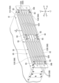
- FIG. 1 is a perspective view of a patch panel according to an embodiment of the present invention.
- FIG. 2 is a view showing a state where an exterior member is removed from FIG. 1 .
- 3 is a view showing a state in which a restricting member and an adapter are removed from FIG. 2 .
- FIG. 3 is a perspective view of the restricting member of FIG. 2 .
- FIG. 4 is a perspective view of the right support pillar of FIG. 3 .
- FIG. 4 is a perspective view of the intermediate strut of FIG. 3 .
- 2A to 2C are diagrams illustrating a procedure for removing some adapters from the patch panel of FIG. 1.
- FIG. 10 is a diagram showing the procedure following FIG. 9 .
- the patch panel 1 includes a housing 2 and a plurality of adapters 3.
- An optical connector 4 can be connected to each adapter 3.
- the housing 2 has a pair of side walls 2a, a bottom wall 2b, and a top wall 2c.
- a plurality of optical fibers and the like connected to each adapter 3 are disposed inside the housing 2.
- the plurality of adapters 3 are two-dimensionally arrayed at an end of the housing 2.
- the left-right direction Y is the direction in which the multiple adapters 3 are arranged.
- the up-down direction Z is the direction in which the multiple adapters 3 are arranged, and is perpendicular to the left-right direction Y. That is, the adapters 3 are two-dimensionally arranged in the left-right direction Y and the up-down direction Z.
- the front-back direction X is a direction perpendicular to both the left-right direction Y and the front-back direction X.
- the front-back direction X is also the direction in which the optical connector 4 is moved when the optical connector 4 is connected to the adapter 3.
- One side (+Z side) in the up-down direction Z is referred to as the upper side, and the other side (-Z side) is referred to as the lower side.
- One side (+Y side) in the left-right direction Y is referred to as the right side, and the other side (-Y side) is referred to as the left side.
- One side (+X side) in the front-back direction X is referred to as the front side, and the other side (-X side) is referred to as the rear side.
- the multiple adapters 3 are located at the front end of the housing 2.
- the patch panel 1 has a generally symmetrical structure overall. For this reason, in the following, the structure of the right half of the patch panel 1 will be described, and the description of the left half may be omitted. However, the structure of the patch panel 1 does not have to be symmetrical.
- FIG. 1 shows a pair of mounting members 2d which are attached to the housing 2.
- the mounting members 2d are used to attach the patch panel 1 to another structure (such as a rack).
- a plurality of exterior members 2e are attached to the housing 2. These exterior members 2e are not necessary.
- FIG. 2 shows the state in which the exterior members 2e have been removed from the housing 2.
- the exterior members 2e can be removed from the housing 2 by removing the screws B1 shown in FIG. 1.
- the housing 2 has a frame F.
- the frame F includes a right support 30A, a left support 30B, and a middle support 40, etc.
- the housing 2 has a plurality of regulating members 10A, 10B, 20A, and 20B attached to the frame F.
- the regulating member 10A (right regulating member) is attached to the right support 30A.
- the regulating member 10B (left regulating member) is attached to the left support 30B.
- the regulating member 20A (first intermediate regulating member) and the regulating member 20B (second intermediate regulating member) are attached to the intermediate support 40.
- These regulating members 10A, 10B, 20A, and 20B are fixed to the frame F by screws B2. Therefore, by removing the screws B2, the regulating members 10A, 10B, 20A, and 20B can be removed from the frame F.
- the fixing means of the regulating members 10A, 10B, 20A, and 20B to the frame F is not limited to the screws B2 and can be changed as appropriate.
- FIG. 3 shows the state in which the restricting members 10A, 10B, 20A, 20B and the multiple adapters 3 have been removed from the housing 2.
- the housing 2 has a front member group 50 and a rear member group 60.
- the front member group 50 and the rear member group 60 are arranged at an interval in the front-to-rear direction X.
- the front member group 50 is located forward of the rear member group 60.
- the front member group 50 includes a plurality of right front members 50A and a plurality of left front members 50B.
- the plurality of right front members 50A extend in the left-right direction Y across the right support column 30A and the middle support column 40.
- the plurality of left front members 50B extend in the left-right direction Y across the left support column 30B and the middle support column 40.
- the plurality of right front members 50A include an upper member 51A (right front upper member), a plurality of intermediate members 52A (right front intermediate members), and a lower member 53A (right front lower member).
- the plurality of left front members 50B include an upper member 51B (left front upper member), a plurality of intermediate members 52B (left front intermediate members), and a lower member 53B (left front lower member).
- the upper member 51A is located at the top, and the lower member 53A is located at the bottom.
- the upper member 51B is located at the top and the lower member 53B is located at the bottom.
- the rear member group 60 includes an upper rear member 61, a lower rear member 63, a plurality of intermediate members 62A (right rear intermediate members), and a plurality of intermediate members 62B (left rear intermediate members).
- the upper rear member 61 is located at the top and the lower rear member 63 is located at the bottom.
- the intermediate members 62A, 62B are located between the upper rear member 61 and the lower rear member 63 in the vertical direction Z.
- the upper rear member 61 extends in the left-right direction Y across the right support 30A, the middle support 40, and the left support 30B.
- the lower rear member 63 extends in the left-right direction Y across the right support 30A, the middle support 40, and the left support 30B.
- the plurality of intermediate members 62A extend in the left-right direction Y across the right support 30A and the middle support 40.
- the multiple intermediate members 62B extend in the left-right direction Y across the left support column 30B and the intermediate support column 40.
- the number of intermediate members 52A, 52B, 62A, and 62B corresponds to the number of arrangements of adapters 3 in the vertical direction Z. Specifically, there are six rows of adapters 3 in the vertical direction Z. The number of intermediate members 52A, 52B, 62A, and 62B is five each. In other words, if the number of arrangements of adapters 3 in the vertical direction Z is N, the number of intermediate members 52A, 52B, 62A, and 62B is N-1 each. However, the number of arrangements of adapters 3 and the number of intermediate members 52A, 52B, 62A, and 62B can be changed.
- the upper members 51A, 51B face the upper rear member 61 in the front-to-rear direction X.
- the intermediate member 52A of the right front member 50A faces the intermediate member 62A of the rear member group 60 in the front-to-rear direction X.
- the intermediate member 52B of the left front member 50B faces the intermediate member 62B of the rear member group 60 in the front-to-rear direction X.
- the lower members 53A, 53B face the lower rear member 63 in the front-to-rear direction X.
- the upper members 51A, 51B and the lower members 53A, 53B are attached to the frame F (right support 30A, middle support 40, left support 30B) by a plurality of screws B3.
- a gap G is provided between the upper members 51A, 51B and the upper rear member 61. Similarly, a gap G is provided between the intermediate members 52A and 62A. A gap G is provided between the intermediate members 52B and 62B. A gap G is provided between the lower members 53A, 53B and the lower rear member 63. These gaps G have the same size. The gap G is used to position the protrusions 3c, 3d of the adapter 3, which will be described later.
- FIG. 4 is a perspective view of the regulating member 10A.
- the regulating member 10A is formed by processing sheet metal. However, the regulating member 10A may be formed by other methods.
- the regulating member 10A has a first regulating portion 11 and a second regulating portion 12.
- the first regulating portion 11 is plate-shaped extending in the up-down direction Z and the left-right direction Y.
- the first regulating portion 11 has two long holes 11a.
- the long holes 11a extend in the left-right direction Y.
- a screw B2 is inserted into the long holes 11a (see FIG. 2).
- the screw B2 is fastened to the screw hole 31b (see FIG. 5) of the right support 30A.
- the regulating member 10A is attached to the right support 30A.
- the regulating member 10A can be removed from the right support 30A.
- the regulating member 10B can be removed from the left support 30B.
- the second restricting portion 12 is plate-shaped and extends in the up-down direction Z and the front-rear direction X.
- the second restricting portion 12 extends rearward from an end (left end) of the first restricting portion 11 in the left-right direction Y.
- the second restricting portion 12 has a plurality of avoidance portions 12a spaced apart in the up-down direction Z.
- the avoidance portions 12a extend in the front-rear direction X and penetrate the second restricting portion 12 in the left-right direction Y.
- Intermediate members 52A, 62A are inserted into these avoidance portions 12a.
- the first restricting portion 11 has a function of restricting the intermediate members 52A of the right front member 50A from moving forward.
- the second restricting portion 12 has a function of restricting the adapters 3 from moving rightward.
- the number of avoidance portions 12a also corresponds to the number of intermediate members 52A, etc., and can be expressed as N-1 (N is the number of adapters 3 arranged in the vertical direction Z).
- Regulating member 10B has a shape that is symmetrical to regulating member 10A. Although detailed illustration is omitted, regulating member 10B, like regulating member 10A, has a first regulating portion, a second regulating portion, two long holes, and multiple avoidance portions.
- FIG. 5 is a perspective view of the right support pillar 30A.
- the right support pillar 30A is formed by processing sheet metal. However, the right support pillar 30A may be formed by other methods.
- the right support pillar 30A has a front wall 31, an inner wall 32, and an upper wall 33.
- the front wall 31 is a plate extending in the up-down direction Z and the left-right direction Y.
- the front wall 31 has the two screw holes 31b mentioned above.
- the inner wall 32 is a plate extending in the up-down direction Z and the front-rear direction X.
- the inner wall 32 extends rearward from the end (left end) of the front wall 31 in the left-right direction Y.
- the upper wall 33 extends rearward from the upper end of the front wall 31.
- the right support pillar 30A has multiple support parts 31a formed at intervals in the vertical direction Z.
- the support parts 31a are slits that penetrate the sheet metal that constitutes the right support pillar 30A in the thickness direction.
- the support parts 31a are formed from the front wall 31 to the inner wall 32.
- the support parts 31a penetrate the front wall 31 in the front-rear direction X.
- the support parts 31a have the function of supporting the intermediate members 52A, 62A.
- the intermediate members 52A, 62A are supported by the right support pillar 30A by being inserted through the support parts 31a.
- the number of support parts 31a corresponds to the number of intermediate members 52A, etc., and can be expressed as N-1 (N is the number of adapters 3 arranged in the vertical direction Z).
- the right support 30A also has multiple rear restriction portions 31c (right rear restriction portions).
- the rear restriction portions 31c have the function of restricting the intermediate member 62A inserted into the support portion 31a from moving rearward.
- the rear end portion of the support portion 31a on the inner wall 32 is the rear restriction portion 31c.
- the left support pillar 30B has a shape that is symmetrical to the right support pillar 30A. Although detailed illustration is omitted, like the right support pillar 30A, the left support pillar 30B also has a front wall, an inner wall, an upper wall, multiple support portions, and multiple rear restriction portions.
- the support portions of the left support pillar 30B support the intermediate members 52B and 62B.
- the rear restriction portion of the left support pillar 30B (left rear restriction portion) restricts the movement of the intermediate member 62B toward the rear.
- FIG. 6 is a perspective view of the intermediate support 40.
- the intermediate support 40 is formed by processing sheet metal. However, the intermediate support 40 may be formed by other methods.
- the intermediate support 40 is located behind the regulating members 20A and 20B shown in FIG. 2 (see also FIG. 3). As shown in FIG. 6, the intermediate support 40 has a front wall 41, a right side wall 42A, a left side wall 42B, and an upper wall 43.
- the front wall 41 is plate-shaped and extends in the up-down direction Z and the left-right direction Y.
- Four screw holes 41b are formed in the front wall 41.
- the regulating members 20A and 20B are attached to the intermediate support 40 by fastening screws B2 (see FIG. 2) into these screw holes 41b.
- the right side wall 42A and the left side wall 42B are plate-shaped extending in the up-down direction Z and the front-rear direction X.
- the right side wall 42A extends rearward from the right end of the front wall 41.
- the left side wall 42B extends rearward from the left end of the front wall 41.
- the right side wall 42A and the left side wall 42B have the function of restricting the movement of the adapter 3 in the left-right direction Y.
- a plurality of adapters 3 are arranged in the space between the right side wall 42A and the second restricting portion 12 of the restricting member 10A.
- a plurality of adapters 3 are arranged in the space between the left side wall 42B and the second restricting portion (not shown) of the restricting member 10B.
- a plurality of intermediate support portions 41a are formed in the intermediate support 40 at intervals in the up-down direction Z.
- the intermediate support portions 41a are slits that penetrate the sheet metal constituting the intermediate support 40 in the thickness direction.
- the intermediate support portion 41a is formed across the right side wall 42A, the front wall 41, and the left side wall 42B.
- the intermediate support portion 41a penetrates the front wall 41 in the front-to-rear direction X.
- the intermediate support portion 41a has the function of supporting the intermediate members 52A, 62A, 52B, and 62B (see Figures 3 and 6).
- the intermediate members 52A, 62A, 52B, and 62B are supported by the intermediate support column 40 by being inserted through the intermediate support portion 41a.
- the number of intermediate support portions 41a also corresponds to the number of intermediate members 52A, etc., and can be expressed as N-1 (N is the number of arrangements of adapters 3 in the vertical direction Z).
- the intermediate support 40 also has multiple rear regulating portions 41c (middle rear regulating portions).
- the rear regulating portions 41c function to regulate the rearward movement of the intermediate members 62A, 62B inserted through the intermediate support portion 41a.
- the rear end portions of the intermediate support portions 41a on the right side wall 42A and the left side wall 42B are the rear regulating portions 41c.
- FIG 7 is a perspective view of the adapter 3.
- the adapter 3 is a square cylinder extending in the front-rear direction X.
- the adapter 3 has a first opening 3a, a second opening 3b, a protrusion 3c (first protrusion), and a protrusion 3d (second protrusion).
- the first opening 3a opens toward the front.
- the optical connector 4 (see Figure 1) is inserted into the inside of the adapter 3 from the first opening 3a.
- the second opening 3b opens toward the rear.
- Another optical connector to be connected to the optical connector 4 is inserted into the inside of the adapter 3 from the second opening 3b.
- the adapter 3 has the function of aligning and connecting optical connectors to each other.
- Protrusion 3c protrudes upward from adapter 3.
- Protrusion 3d protrudes downward from adapter 3.
- Protrusions 3c and 3d are disposed at the same position as each other in the front-to-rear direction X. Specifically, protrusions 3c and 3d are disposed in the center of adapter 3 in the front-to-rear direction X. Protrusions 3c and 3d extend in the left-to-right direction Y.
- FIG. 8 is a cross-sectional view taken along line VIII-VIII in FIG. 2, and is an enlarged view of the upper end of patch panel 1. Note that the position of line VIII-VIII in FIG. 2 (the position of the cross section in FIG. 8) is the right side of patch panel 1, but the left side of patch panel 1 has a similar cross section. For this reason, the reference numbers for upper member 51A on the right and upper member 51B on the left are shown together in FIG. 8. The same is true for members other than upper members 51A and 51B.
- the upper protrusion 3c of the uppermost adapter 3 is sandwiched between the upper rear member 61 and the upper member 51A, or between the upper rear member 61 and the upper member 51B.
- the lower protrusion 3d of the uppermost adapter 3 is sandwiched between the intermediate members 62A and 52A, or between the intermediate members 62B and 52B. This determines the position of the adapter 3 in the front-rear direction X.
- the lower protrusion 3d of the lowermost adapter 3 is sandwiched between the lower rear member 63 and the lower member 53A, or between the lower rear member 63 and the lower member 53B.
- the protrusions 3c and 3d of the adapter 3 located in the middle in the vertical direction Z are sandwiched between the intermediate members 62A and 52A, or between the intermediate members 62B and 52B.
- the size of the gap G mentioned above corresponds to the thickness of the protrusions 3c and 3d in the front-rear direction X.
- the protrusion 3d of the adapter 3 located above is in contact with the protrusion 3c of the adapter 3 located below.
- the adapters 3 arranged in the vertical direction Z are arranged so that their protrusions 3c, 3d are in contact with each other. This makes it possible to reduce the overall dimension of the patch panel 1 in the vertical direction Z.
- the overall height of the patch panel 1 is less than 2U.
- U unit is a unit of length defined by standards and is approximately 44.45 mm.
- the patch panel 1 of this embodiment has a total of 216 adapters 3. More specifically, the adapters 3 are two-dimensionally arranged in six rows in the vertical direction Z and 36 rows in the horizontal direction Y. Two optical connectors 4 can be connected to one adapter 3. As shown in the enlarged view in FIG. 1, each optical connector 4 has two single-core ferrules 4a (ferrules with one optical fiber 4b built in). Therefore, a total of 864 (216 x 2 x 2) optical fibers 4b can be connected to the patch panel 1 of this embodiment.
- the existing patch panel with a height of 2U can connect 288 optical fibers. Therefore, the patch panel 1 of this embodiment can achieve a wiring density three times that of existing products.
- the optical connector 4 may include one 16-core ferrule (a ferrule with 16 built-in optical fibers). In this case, a total of 6,912 (216 x 2 x 16) optical fibers can be connected.
- the optical connector 4 may include one 24-core ferrule (a ferrule with 24 built-in optical fibers). In this case, a total of 10,368 (216 x 2 x 24) optical fibers can be connected.
- the front group of members 50 and the rear group of members 60 are supported by a frame F. Specifically, both ends in the left-right direction Y of the upper rear member 61 and the lower rear member 63 are supported by the right support column 30A and the left support column 30B. Both ends in the left-right direction Y of the upper member 51A, the intermediate members 52A, 62A, and the lower member 53A are supported by the right support column 30A and the intermediate support column 40, respectively. Both ends in the left-right direction Y of the upper member 51B, the intermediate members 52B, 62B, and the lower member 53B are supported by the left support column 30B and the intermediate support column 40, respectively.
- the upper members 51A, 51B or the lower members 53A, 53B can be removed by unscrewing the screw B3.
- the other steps are the same as those described above.
- the movement of the upper members 51A, 51B and the lower members 53A, 53B relative to the frame F is restricted by the screw B3.
- the restricting members 10A, 10B, 20A, 20B restrict the forward movement of the upper members 51A, 51B and the lower members 53A, 53B.
- the restricting members 10A, 10B, 20A, 20B may restrict the movement of all of the front member group 50 relative to the frame F.
- the patch panel 1 of this embodiment includes a housing 2 and a plurality of adapters 3 having protrusions 3c.
- the housing 2 includes a frame F having a right support 30A and a left support 30B spaced apart in the left-right direction Y, and capable of arranging a plurality of adapters 3 between the right support 30A and the left support 30B, a front member group 50 supported by the frame F and abutting against each of the protrusions 3c of the plurality of adapters 3, a rear member group 60 spaced apart from the front member group 50 in the front-rear direction X perpendicular to the left-right direction Y and abutting against each of the protrusions 3c of the plurality of adapters 3, and restricting members 10A, 10B, 20A, 20B that restrict the movement of at least a portion of the front member group 50 (intermediate members 52A, 52B) relative to the frame F.
- the restricting members 10A, 10B, 20A, 20B move relative to the frame
- the protrusion 3c of the adapter 3 is sandwiched between the front member group 50 and the rear member group 60 in the front-rear direction X. Therefore, the position of the adapter 3 in the front-rear direction X can be determined.
- the front member group 50 becomes movable relative to the frame F. By moving the front member group 50, the positioning of the adapter 3 is released, and it becomes possible to move the adapter 3 in the front-rear direction.
- the force applied to the adapter 3 when removing the adapter 3 can be reduced, compared to when the adapter 3 is fixed to the housing 2 by, for example, a snap fit. Therefore, it is also possible to suppress the application of a strong force to the optical fiber 3f (see FIG. 10) connected to the adapter 3.
- each of the multiple adapters 3 has a second protrusion 3d that protrudes in the opposite direction to the protrusion 3c.
- the protrusions 3c and second protrusions 3d of the multiple adapters 3 are sandwiched in the front-rear direction X by the front member group 50 and the rear member group 60. This configuration makes it possible to more reliably position each adapter 3 in the front-rear direction X.
- the multiple adapters 3 also include two adapters adjacent in the up-down direction Z, which is perpendicular to both the left-right direction Y and the front-back direction X, and the protrusion 3c of one of the two adapters 3 is in contact with the second protrusion 3d of the other of the two adapters.
- the multiple adapters 3 are arranged without any gaps in the up-down direction Z, so that the protrusions 3c, 3d are in contact with each other. This makes it possible to reduce the overall dimension of the patch panel 1 in the up-down direction Z. Therefore, the adapters 3 can be arranged with a higher density.
- the frame F has an intermediate support 40 disposed between the right support 30A and the left support 30B, and the front member group 50 includes a plurality of right front members 50A whose both ends are supported by the right support 30A and the intermediate support 40, and a plurality of left front members 50B whose both ends are supported by the left support 30B and the intermediate support 40.
- the dimension of the front member group 50 in the left-right direction Y can be reduced. This makes it possible to prevent a decrease in the rigidity of the front member group 50 when the dimension of the housing 2 in the left-right direction Y is large.
- the multiple adapters 3 include 36 adapters 3 arranged in a row in the left-right direction Y, with half of the 36 adapters 3 being arranged between the right support 30A and the middle support 40, and the remaining half being arranged between the left support 30B and the middle support 40.
- the patch panel 1 of this embodiment is capable of stably holding such a large number of adapters 3, and each adapter 3 can be easily attached and detached.
- the multiple adapters 3 may be connectable to multiple optical connectors 4 having a total of 864 optical fibers. Alternatively, the multiple adapters 3 may be connectable to multiple optical connectors 4 having a total of 6912 optical fibers. Alternatively, the multiple adapters 3 may be connectable to multiple optical connectors 4 having a total of 10368 optical fibers. These configurations make it possible to provide a patch panel 1 that allows for high-density wiring of optical fibers.
- the frame F in the above embodiment had an intermediate support 40.
- the frame F does not have to have an intermediate support 40.
- both ends of the front member group 50 in the left-right direction Y may be supported by the right support 30A and the left support 30B.
- both ends of the rear member group 60 in the left-right direction Y may be supported by the right support 30A and the left support 30B.
- the force applied to the adapter 3 when removing the adapter 3 can be reduced.
- the housing 2 in the above embodiment has four regulating members 10A, 10B, 20A, and 20B, the number of regulating members may be changed.
- the movement of the front member group 50 may be regulated by a single member that integrates the regulating members 20A and 20B.
Landscapes
- Physics & Mathematics (AREA)
- General Physics & Mathematics (AREA)
- Optics & Photonics (AREA)
- Mechanical Coupling Of Light Guides (AREA)
- Light Guides In General And Applications Therefor (AREA)
Priority Applications (1)
| Application Number | Priority Date | Filing Date | Title |
|---|---|---|---|
| JP2025503578A JPWO2024180827A1 (https=) | 2023-02-28 | 2023-11-17 |
Applications Claiming Priority (2)
| Application Number | Priority Date | Filing Date | Title |
|---|---|---|---|
| JP2023-029662 | 2023-02-28 | ||
| JP2023029662 | 2023-02-28 |
Publications (1)
| Publication Number | Publication Date |
|---|---|
| WO2024180827A1 true WO2024180827A1 (ja) | 2024-09-06 |
Family
ID=92590213
Family Applications (1)
| Application Number | Title | Priority Date | Filing Date |
|---|---|---|---|
| PCT/JP2023/041481 Ceased WO2024180827A1 (ja) | 2023-02-28 | 2023-11-17 | パッチパネル |
Country Status (2)
| Country | Link |
|---|---|
| JP (1) | JPWO2024180827A1 (https=) |
| WO (1) | WO2024180827A1 (https=) |
Citations (5)
| Publication number | Priority date | Publication date | Assignee | Title |
|---|---|---|---|---|
| JPS6190104A (ja) * | 1984-10-09 | 1986-05-08 | Nec Corp | 光アダプタの設置構造 |
| US5511144A (en) * | 1994-06-13 | 1996-04-23 | Siecor Corporation | Optical distribution frame |
| JPH1184176A (ja) * | 1997-09-10 | 1999-03-26 | Kitagawa Ind Co Ltd | アダプタ保持具 |
| US20200073060A1 (en) * | 2018-08-31 | 2020-03-05 | Ortronics, Inc. | Detachable Bezel for Cassette Mounting |
| CN213240603U (zh) * | 2020-06-24 | 2021-05-18 | 深圳市飞速创新技术股份有限公司 | 光纤配线箱 |
-
2023
- 2023-11-17 JP JP2025503578A patent/JPWO2024180827A1/ja active Pending
- 2023-11-17 WO PCT/JP2023/041481 patent/WO2024180827A1/ja not_active Ceased
Patent Citations (5)
| Publication number | Priority date | Publication date | Assignee | Title |
|---|---|---|---|---|
| JPS6190104A (ja) * | 1984-10-09 | 1986-05-08 | Nec Corp | 光アダプタの設置構造 |
| US5511144A (en) * | 1994-06-13 | 1996-04-23 | Siecor Corporation | Optical distribution frame |
| JPH1184176A (ja) * | 1997-09-10 | 1999-03-26 | Kitagawa Ind Co Ltd | アダプタ保持具 |
| US20200073060A1 (en) * | 2018-08-31 | 2020-03-05 | Ortronics, Inc. | Detachable Bezel for Cassette Mounting |
| CN213240603U (zh) * | 2020-06-24 | 2021-05-18 | 深圳市飞速创新技术股份有限公司 | 光纤配线箱 |
Also Published As
| Publication number | Publication date |
|---|---|
| JPWO2024180827A1 (https=) | 2024-09-06 |
Similar Documents
| Publication | Publication Date | Title |
|---|---|---|
| US7873253B2 (en) | Adapter panel with lateral sliding adapter arrays | |
| US8195022B2 (en) | Fiber optic adapter cassette and panel | |
| US9690066B2 (en) | Adapter panel with lateral sliding adapter arrays | |
| JP3949661B2 (ja) | ファイバ光学部品のための高密度モジューラ・バックプレーン・コネクタ | |
| US8139913B2 (en) | Modules including multiple rows of adapters for high density optical fiber distribution frame | |
| JP2002048946A (ja) | 複数の光コネクタを組み立てるためのアダプタ | |
| WO2004052066A1 (ja) | 電子装置に搭載されるユニット及び当該電子装置の伝送線路の接続機構 | |
| EP3796061B1 (en) | Ejectable cassette and guide column | |
| US20220128785A1 (en) | Patch panel with lifting cassette removal | |
| US20140185992A1 (en) | Fiber optic module housing and fiber optic module | |
| WO2024180827A1 (ja) | パッチパネル | |
| JP6633596B2 (ja) | 光モジュール | |
| JP7788007B2 (ja) | スロット部材およびこれを含む電力電子機器 | |
| US6533463B2 (en) | Adjustable and modular backplane assembly for providing a fiber-optics communication backplane | |
| JP4332148B2 (ja) | 空間構造体 | |
| US6216999B1 (en) | Floating mount and method for mounting a device to a chassis thereby | |
| KR102492328B1 (ko) | 멀티 카세트 광분배반 | |
| US20080252861A1 (en) | Rear projection type display apparatus | |
| JP4160494B2 (ja) | 光配線箱 | |
| JP4252435B2 (ja) | 光配線箱及びこの配線箱を備えた光集合モジュール | |
| JP5079662B2 (ja) | 空間構造体 | |
| JPH0993764A (ja) | ワイヤーハーネスの取り付け装置 | |
| JPWO2024180827A5 (https=) | ||
| WO2023248526A1 (ja) | 光接続アセンブリ | |
| JP2623974B2 (ja) | 光コネクタ |
Legal Events
| Date | Code | Title | Description |
|---|---|---|---|
| 121 | Ep: the epo has been informed by wipo that ep was designated in this application |
Ref document number: 23925380 Country of ref document: EP Kind code of ref document: A1 |
|
| WWE | Wipo information: entry into national phase |
Ref document number: 2025503578 Country of ref document: JP |
|
| NENP | Non-entry into the national phase |
Ref country code: DE |
|
| 122 | Ep: pct application non-entry in european phase |
Ref document number: 23925380 Country of ref document: EP Kind code of ref document: A1 |