WO2024180625A1 - エアロゾル生成装置の電源ユニット、制御方法、及び制御プログラム - Google Patents
エアロゾル生成装置の電源ユニット、制御方法、及び制御プログラム Download PDFInfo
- Publication number
- WO2024180625A1 WO2024180625A1 PCT/JP2023/007123 JP2023007123W WO2024180625A1 WO 2024180625 A1 WO2024180625 A1 WO 2024180625A1 JP 2023007123 W JP2023007123 W JP 2023007123W WO 2024180625 A1 WO2024180625 A1 WO 2024180625A1
- Authority
- WO
- WIPO (PCT)
- Prior art keywords
- temperature
- power supply
- power source
- charging
- current value
- Prior art date
- Legal status (The legal status is an assumption and is not a legal conclusion. Google has not performed a legal analysis and makes no representation as to the accuracy of the status listed.)
- Ceased
Links
Images


Classifications
-
- A—HUMAN NECESSITIES
- A24—TOBACCO; CIGARS; CIGARETTES; SIMULATED SMOKING DEVICES; SMOKERS' REQUISITES
- A24F—SMOKERS' REQUISITES; MATCH BOXES; SIMULATED SMOKING DEVICES
- A24F40/00—Electrically operated smoking devices; Component parts thereof; Manufacture thereof; Maintenance or testing thereof; Charging means specially adapted therefor
- A24F40/90—Arrangements or methods specially adapted for charging batteries thereof
-
- A—HUMAN NECESSITIES
- A24—TOBACCO; CIGARS; CIGARETTES; SIMULATED SMOKING DEVICES; SMOKERS' REQUISITES
- A24F—SMOKERS' REQUISITES; MATCH BOXES; SIMULATED SMOKING DEVICES
- A24F40/00—Electrically operated smoking devices; Component parts thereof; Manufacture thereof; Maintenance or testing thereof; Charging means specially adapted therefor
- A24F40/10—Devices using liquid inhalable precursors
-
- A—HUMAN NECESSITIES
- A24—TOBACCO; CIGARS; CIGARETTES; SIMULATED SMOKING DEVICES; SMOKERS' REQUISITES
- A24F—SMOKERS' REQUISITES; MATCH BOXES; SIMULATED SMOKING DEVICES
- A24F40/00—Electrically operated smoking devices; Component parts thereof; Manufacture thereof; Maintenance or testing thereof; Charging means specially adapted therefor
- A24F40/40—Constructional details, e.g. connection of cartridges and battery parts
- A24F40/46—Shape or structure of electric heating means
-
- A—HUMAN NECESSITIES
- A24—TOBACCO; CIGARS; CIGARETTES; SIMULATED SMOKING DEVICES; SMOKERS' REQUISITES
- A24F—SMOKERS' REQUISITES; MATCH BOXES; SIMULATED SMOKING DEVICES
- A24F40/00—Electrically operated smoking devices; Component parts thereof; Manufacture thereof; Maintenance or testing thereof; Charging means specially adapted therefor
- A24F40/50—Control or monitoring
- A24F40/57—Temperature control
-
- H—ELECTRICITY
- H02—GENERATION; CONVERSION OR DISTRIBUTION OF ELECTRIC POWER
- H02J—ELECTRIC POWER NETWORKS; CIRCUIT ARRANGEMENTS OR SYSTEMS FOR SUPPLYING OR DISTRIBUTING ELECTRIC POWER; SYSTEMS FOR STORING ELECTRIC ENERGY
- H02J7/00—Circuit arrangements for charging or discharging batteries or for supplying loads from batteries
- H02J7/60—Circuit arrangements for charging or discharging batteries or for supplying loads from batteries including safety or protection arrangements
- H02J7/64—Circuit arrangements for charging or discharging batteries or for supplying loads from batteries including safety or protection arrangements against overvoltage
-
- H—ELECTRICITY
- H02—GENERATION; CONVERSION OR DISTRIBUTION OF ELECTRIC POWER
- H02J—ELECTRIC POWER NETWORKS; CIRCUIT ARRANGEMENTS OR SYSTEMS FOR SUPPLYING OR DISTRIBUTING ELECTRIC POWER; SYSTEMS FOR STORING ELECTRIC ENERGY
- H02J7/00—Circuit arrangements for charging or discharging batteries or for supplying loads from batteries
- H02J7/90—Regulation of charging or discharging current or voltage
- H02J7/96—Regulation of charging or discharging current or voltage in response to battery voltage
-
- H—ELECTRICITY
- H02—GENERATION; CONVERSION OR DISTRIBUTION OF ELECTRIC POWER
- H02J—ELECTRIC POWER NETWORKS; CIRCUIT ARRANGEMENTS OR SYSTEMS FOR SUPPLYING OR DISTRIBUTING ELECTRIC POWER; SYSTEMS FOR STORING ELECTRIC ENERGY
- H02J7/00—Circuit arrangements for charging or discharging batteries or for supplying loads from batteries
- H02J7/90—Regulation of charging or discharging current or voltage
- H02J7/971—Regulation of charging or discharging current or voltage the charge cycle being controlled or terminated in response to non-electric parameters
- H02J7/975—Regulation of charging or discharging current or voltage the charge cycle being controlled or terminated in response to non-electric parameters in response to temperature
- H02J7/977—Regulation of charging or discharging current or voltage the charge cycle being controlled or terminated in response to non-electric parameters in response to temperature of the battery
-
- H—ELECTRICITY
- H02—GENERATION; CONVERSION OR DISTRIBUTION OF ELECTRIC POWER
- H02J—ELECTRIC POWER NETWORKS; CIRCUIT ARRANGEMENTS OR SYSTEMS FOR SUPPLYING OR DISTRIBUTING ELECTRIC POWER; SYSTEMS FOR STORING ELECTRIC ENERGY
- H02J2207/00—Details of circuit arrangements for charging or discharging batteries or supplying loads from batteries
- H02J2207/10—Control circuit supply, e.g. means for supplying power to the control circuit
-
- H—ELECTRICITY
- H02—GENERATION; CONVERSION OR DISTRIBUTION OF ELECTRIC POWER
- H02J—ELECTRIC POWER NETWORKS; CIRCUIT ARRANGEMENTS OR SYSTEMS FOR SUPPLYING OR DISTRIBUTING ELECTRIC POWER; SYSTEMS FOR STORING ELECTRIC ENERGY
- H02J2207/00—Details of circuit arrangements for charging or discharging batteries or supplying loads from batteries
- H02J2207/30—Charge provided using DC bus or data bus of a computer
-
- Y—GENERAL TAGGING OF NEW TECHNOLOGICAL DEVELOPMENTS; GENERAL TAGGING OF CROSS-SECTIONAL TECHNOLOGIES SPANNING OVER SEVERAL SECTIONS OF THE IPC; TECHNICAL SUBJECTS COVERED BY FORMER USPC CROSS-REFERENCE ART COLLECTIONS [XRACs] AND DIGESTS
- Y02—TECHNOLOGIES OR APPLICATIONS FOR MITIGATION OR ADAPTATION AGAINST CLIMATE CHANGE
- Y02E—REDUCTION OF GREENHOUSE GAS [GHG] EMISSIONS, RELATED TO ENERGY GENERATION, TRANSMISSION OR DISTRIBUTION
- Y02E60/00—Enabling technologies; Technologies with a potential or indirect contribution to GHG emissions mitigation
- Y02E60/10—Energy storage using batteries
Definitions
- This disclosure relates to a power supply unit, a control method, and a control program for an aerosol generating device.
- aerosol generating devices that generate aerosols containing, for example, flavor components and allow a user to inhale the generated aerosol.
- aerosol generating devices generate aerosol by supplying power from a power source such as a rechargeable battery to a heating section (also called a "heating element") that is an electric resistance or induction heater, and heating an aerosol source with the heating section.
- Patent Document 1 discloses a technology that monitors the ambient temperature adjacent to a charging device that includes a rechargeable power source, determines a charging current depending on the ambient temperature in order to charge the rechargeable power source of the charging device, and charges the rechargeable power source of the charging device with the determined charging current.
- Patent Document 2 discloses a technology in which a first control unit of a power supply unit having a power supply electrically connected to a load that atomizes an aerosol source or heats a flavor source, and a second control unit of a charging unit capable of charging the power supply, control the charging speed of the power supply.
- This disclosure provides a power supply unit, control method, and control program for an aerosol generating device that enables higher quality charging control.
- a power supply unit of an aerosol generating device for generating an aerosol by heating an aerosol source comprising: a power source capable of supplying power to a heating unit that heats the aerosol source and configured to be chargeable by power received from an external power source; a control unit configured to acquire a temperature of the power source and to control charging of the power source based on the acquired temperature of the power source; Equipped with The control unit is When the temperature of the power source is included in a first temperature range, which is a temperature range below a predetermined threshold temperature, a current value of a charging current for charging the power source is changed within a predetermined range according to the temperature of the power source; When the temperature of the power source is included in a second temperature range that is a temperature range equal to or higher than the threshold temperature, the current value of the charging current is made smaller than the lower limit value of the predetermined range. It is a power supply unit.
- a computer-implemented control method for controlling a power supply unit of an aerosol generating device that generates an aerosol by heating an aerosol source comprising: the power supply unit is capable of supplying power to a heating section that heats the aerosol source, and includes a power supply configured to be rechargeable by power received from an external power supply; the computer is configured to be capable of acquiring a temperature of the power source and to control charging of the power source based on the acquired temperature of the power source; The computer, When the temperature of the power source is included in a first temperature range, which is a temperature range below a predetermined threshold temperature, a current value of a charging current for charging the power source is changed within a predetermined range according to the temperature of the power source; When the temperature of the power source is included in a second temperature range that is a temperature range equal to or higher than the threshold temperature, the current value of the charging current is made smaller than the lower limit value of the predetermined range. It is a control method for performing processing.
- a control program for causing a computer to perform a predetermined process to control a power supply unit of an aerosol generating device that generates an aerosol by heating an aerosol source, the power supply unit is capable of supplying power to a heating section that heats the aerosol source, and includes a power supply configured to be rechargeable by power received from an external power supply; the computer is configured to be capable of acquiring a temperature of the power source and to control charging of the power source based on the acquired temperature of the power source;
- the computer includes: When the temperature of the power source is included in a first temperature range, which is a temperature range below a predetermined threshold temperature, a current value of a charging current for charging the power source is changed within a predetermined range according to the temperature of the power source; When the temperature of the power source is included in a second temperature range that is a temperature range equal to or higher than the threshold temperature, the current value of the charging current is made smaller than the lower limit value of the predetermined range. It is a control program that performs the
- This disclosure provides a power supply unit, control method, and control program for an aerosol generating device that enables higher quality charging control.
- FIG. 1A is a schematic diagram showing a first configuration example of a suction device.
- FIG. 1B is a schematic diagram showing a second configuration example of the suction device.
- FIG. 2 is a schematic diagram showing an example of the configuration of a portion of the suction device 100 that is involved in charging the power supply unit 111.
- FIG. 3 is a diagram showing an example of charging control in the suction device 100.
- FIG. 4 is a diagram showing another example of charging control in the suction device 100.
- FIG. FIG. 5 is a flowchart showing an example of a process performed by the MCU 104.
- FIG. 6 is a flowchart showing an example of a process performed by the charging IC 103.
- An inhalation device which is an example of an aerosol generating device of the present disclosure, is a device that generates a substance to be inhaled by a user.
- the substance generated by the inhalation device is described as an aerosol.
- the substance generated by the inhalation device may be a gas.
- FIG. 1A is a schematic diagram showing a first configuration example of an inhalation device.
- an inhalation device 100A of this configuration example includes a power supply unit 110, a cartridge 120, and a flavoring cartridge 130.
- the power supply unit 110 includes a power supply section 111A, a sensor section 112A, a notification section 113A, a memory section 114A, a communication section 115A, and a control section 116A.
- the cartridge 120 includes a heating section 121A, a liquid guiding section 122, and a liquid storage section 123.
- the flavoring cartridge 130 includes a flavor source 131 and a mouthpiece 124.
- An air flow path 180 is formed in the cartridge 120 and the flavoring cartridge 130.
- the power supply unit 111A accumulates power.
- the power supply unit 111A supplies power to each component of the suction device 100A based on the control of the control unit 116A.
- the power supply unit 111A is also configured to be rechargeable by power received from an external power source.
- the power supply unit 111A may be configured, for example, by a rechargeable battery such as a lithium ion secondary battery.
- the sensor unit 112A acquires various information related to the suction device 100A.
- the sensor unit 112A is composed of, for example, a pressure sensor such as a condenser microphone, a flow rate sensor, or a temperature sensor, and acquires values associated with the user's suction.
- the sensor unit 112A may include a pressure sensor (also referred to as a "puff sensor”) capable of detecting a change in pressure (hereinafter also referred to as "internal pressure") inside the suction device 100A caused by the user's inhalation.
- the sensor unit 112A may include a flow rate sensor capable of detecting a flow rate (hereinafter also simply referred to as "flow rate") caused by the user's inhalation.
- the sensor unit 112A may include a temperature sensor (also referred to as a "puff thermistor”) capable of detecting the temperature of the heating unit 121A or the area around the heating unit 121A.
- the sensor unit 112A may include a temperature sensor (for example, the battery temperature sensor 101 in FIG. 2) capable of detecting the temperature of the power supply unit 111A or the area around the power supply unit 111A.
- the sensor unit 112A may also be configured to include an input device, such as an operation button or a switch, that accepts information input from a user.
- an input device such as an operation button or a switch
- the sensor unit 112A may include an operation button as an input device that accepts a request to start charging, which will be described later.
- Notification unit 113A notifies the user of information.
- Notification unit 113A may be configured, for example, as a light-emitting device that emits light, a display device that displays an image, a sound output device that outputs sound, or a vibration device that vibrates.
- the storage unit 114A stores various information (e.g., programs and data) for the operation of the suction device 100A.
- the storage unit 114A may be configured, for example, from a non-volatile storage medium such as a flash memory.
- the communication unit 115A is a communication interface capable of performing communication conforming to any wired or wireless communication standard.
- Such communication standards may include, for example, standards using Wi-Fi (registered trademark), Bluetooth (registered trademark), BLE (Bluetooth Low Energy (registered trademark)), NFC (Near Field Communication), or LPWA (Low Power Wide Area).
- the control unit 116A functions as an arithmetic processing unit and a control unit, and controls the overall operation of the suction device 100A in accordance with various programs stored in the memory unit 114A, etc.
- the control unit 116A controls the power supply (electricity supply) from the power supply unit 111A to each component (e.g., the heating unit 121A described below), and the charging of the power supply unit 111A with electric power received from the external power supply PS.
- the control unit 116A is realized by an electronic circuit such as a CPU (Central Processing Unit) or a microprocessor.
- the control unit 116A can be realized by the MCU 104 (MCU: Micro Controller Unit) described below, etc.
- the liquid storage unit 123 stores the aerosol source.
- the aerosol source is atomized to generate an aerosol.
- the aerosol source is a liquid such as, for example, a polyhydric alcohol such as glycerin and propylene glycol, or water.
- the aerosol source may contain a tobacco-derived or non-tobacco-derived flavor component. If the inhalation device 100A is a medical inhaler such as a nebulizer, the aerosol source may contain a medicine.
- the liquid guide section 122 guides and holds the aerosol source, which is a liquid stored in the liquid storage section 123, from the liquid storage section 123.
- the liquid guide section 122 is, for example, a wick formed by twisting a fiber material such as glass fiber or a porous material such as porous ceramic. In this case, the aerosol source stored in the liquid storage section 123 is guided by the capillary effect of the wick.
- the heating unit 121A generates an aerosol by, for example, heating the aerosol source and atomizing the aerosol source.
- the heating unit 121A is configured in any shape, such as a coil, film, or blade, and is made of any material, such as metal or polyimide.
- the heating unit 121A is configured as a coil wound with a heating resistor, such as nichrome or stainless steel, and is wrapped around the liquid guide unit 122.
- a heating resistor such as nichrome or stainless steel
- power supply to the heating unit 121A may be performed when the sensor unit 112A detects that the user has started inhaling and/or that specific information has been input. Then, power supply to the heating unit 121A may be stopped when the sensor unit 112A detects that the user has stopped inhaling and/or that specific information has been input.
- the heating unit 121A may be configured to generate aerosols by vibration or induction heating.
- the suction device 100A includes a vibration unit as the heating unit 121A.
- the vibration unit is configured, for example, of a plate-shaped member containing piezoelectric ceramics that functions as an ultrasonic vibrator.
- the aerosol source guided to the surface of the vibration unit by the liquid guide unit 122 is atomized by ultrasonic waves generated by the vibration of the vibration unit, and an aerosol is generated.
- the suction device 100A When the aerosol is generated by induction heating, the suction device 100A includes a susceptor and an electromagnetic induction source as the heating unit 121A.
- the susceptor is made of a conductive material such as metal, and generates heat by electromagnetic induction.
- the susceptor is disposed close to the liquid guide unit 122.
- the susceptor is made of a metal conductor and is wound around the liquid guide unit 122.
- the electromagnetic induction source causes the susceptor to generate heat by electromagnetic induction.
- the electromagnetic induction source is made of, for example, a coiled conductor, and generates a magnetic field when an alternating current is supplied from the power supply unit 111A. When a magnetic field is generated, an eddy current is generated in the susceptor, generating Joule heat.
- the aerosol source held in the liquid guide unit 122 is heated and atomized by the Joule heat, and an aerosol is generated.
- the flavor source 131 is a component for imparting flavor components to the aerosol.
- the flavor source 131 includes flavor components derived from tobacco or non-tobacco.
- the flavor source 131 may be derived from tobacco, such as a processed product in which cut tobacco or tobacco raw materials are formed into a granular, sheet, or powder form.
- the flavor source 131 may also include a non-tobacco-derived product made from plants other than tobacco (e.g., mint and herbs).
- the flavor source 131 may include a flavor component such as menthol.
- the flavor source 131 may also be a stick-shaped member.
- the flavor source 131 may include a drug for the patient to inhale.
- the flavor source 131 is not limited to a solid, and may be a liquid containing flavor components such as polyhydric alcohols such as glycerin and propylene glycol, and water.
- the flavor source 131 may also be placed inside a container such as a capsule.
- the air flow path 180 is a flow path for air inhaled by the user.
- the air flow path 180 has a tubular structure with an air inlet hole 181, which is an entrance of air into the air flow path 180, and an air outlet hole 182, which is an exit of air from the air flow path 180, at both ends.
- the liquid guide section 122 is arranged on the upstream side (the side closer to the air inlet hole 181), and the flavor source 131 is arranged on the downstream side (the side closer to the air outlet hole 182).
- the air flowing in from the air inlet hole 181 as the user inhales is mixed with the aerosol generated by the heating section 121A, and as shown by the arrow 190, is transported through the flavor source 131 to the air outlet hole 182.
- the flavor components contained in the flavor source 131 are imparted to the aerosol.
- the mouthpiece 124 is a member that is held by the user when inhaling.
- An air outlet hole 182 is arranged in the mouthpiece 124.
- the configuration of the suction device 100A is not limited to the above, and various configurations such as those shown below are possible.
- the inhalation device 100A may not include a flavoring cartridge 130.
- the cartridge 120 is provided with a mouthpiece 124.
- the inhalation device 100A may further include a flavor source heating unit (not shown) that heats the flavor source 131.
- the flavor source heating unit is, for example, configured in a film shape and arranged to cover the outer periphery of the flavor source 131.
- the flavor source heating unit generates heat when power is supplied from the power supply unit 111A, and heats the flavor source 131 from the outer periphery.
- the flavor source heating unit may be, for example, configured in a blade shape, and may pierce the flavor source 131 to heat the flavor source 131 from the inside.
- the flavor source heating unit may also be configured to heat the flavor source 131 by vibration or induction heating.
- the suction device 100A may include multiple types of aerosol sources. Multiple types of aerosols generated from the multiple types of aerosol sources may be mixed in the air flow path 180 and undergo a chemical reaction to generate further types of aerosols.
- the means for atomizing the aerosol source is not limited to heating by the heating unit 121A.
- the means for atomizing the aerosol source may be vibration atomization or induction heating.
- Second configuration example of suction device> 1B is a schematic diagram showing a second configuration example of the suction device.
- the suction device 100B of this configuration example includes a power supply unit 111B, a sensor unit 112B, a notification unit 113B, a storage unit 114B, a communication unit 115B, a control unit 116B, a heating unit 121B, a storage unit 140, and a heat insulating unit 144.
- Each of the power supply unit 111B, the sensor unit 112B, the notification unit 113B, the memory unit 114B, the communication unit 115B, and the control unit 116B is substantially the same as the corresponding components included in the suction device 100A described above.
- the suction device 100B shown in FIG. 1B the suction device 100B itself can be considered a power supply unit.
- the storage section 140 has an internal space 141 and holds the stick-shaped substrate 150 while storing a part of the stick-shaped substrate 150 in the internal space 141.
- the storage section 140 has an opening 142 that connects the internal space 141 to the outside, and stores the stick-shaped substrate 150 inserted into the internal space 141 through the opening 142.
- the storage section 140 is a cylindrical body with the opening 142 and the bottom 143 as the bottom surface, and defines a columnar internal space 141.
- An air flow path that supplies air to the internal space 141 is connected to the storage section 140.
- An air inlet hole which is an air inlet to the air flow path, is arranged, for example, on the side of the suction device 100.
- An air outlet hole which is an air outlet from the air flow path to the internal space 141, is arranged, for example, on the bottom 143.
- the stick-type substrate 150 includes a substrate portion 151 and a mouthpiece portion 152.
- the substrate portion 151 includes an aerosol source.
- the aerosol source includes a tobacco-derived or non-tobacco-derived flavor component.
- the aerosol source may include a medicine.
- the aerosol source may be, for example, a liquid such as a polyhydric alcohol such as glycerin and propylene glycol, and water, which includes a tobacco-derived or non-tobacco-derived flavor component, or may be a solid which includes a tobacco-derived or non-tobacco-derived flavor component.
- the stick-type substrate 150 When the stick-type substrate 150 is held in the storage portion 140, at least a portion of the substrate portion 151 is stored in the internal space 141, and at least a portion of the mouthpiece portion 152 protrudes from the opening 142.
- the suction mouth portion 152 protruding from the opening 142 in their mouth and inhales air flows into the internal space 141 via an air flow path (not shown) and reaches the user's mouth together with the aerosol generated from the base portion 151.
- the heating section 121B is configured as a film heater with conductive tracks made of a heating resistor that has a correlation between electrical resistance and temperature, and is arranged to cover the outer periphery of the storage section 140.
- the heating section 121B generates heat, the substrate section 151 of the stick-shaped substrate 150 is heated from the outer periphery, and an aerosol is generated.
- the heating resistor of the heating section 121B can be the same as the heating resistor of the heating section 121A described above.
- the insulating section 144 prevents heat transfer from the heating section 121B to other components.
- the insulating section 144 is made of a vacuum insulating material or an aerogel insulating material.
- the configuration of the suction device 100B is not limited to the above, and various configurations such as those shown below are possible.
- the heating section 121B may be configured in a blade shape and disposed so as to protrude from the bottom 143 of the storage section 140 into the internal space 141. In that case, the blade-shaped heating section 121B is inserted into the substrate section 151 of the stick-shaped substrate 150 and heats the substrate section 151 of the stick-shaped substrate 150 from the inside. As another example, the heating section 121B may be disposed so as to cover the bottom 143 of the storage section 140. Furthermore, the heating section 121B may be configured as a combination of two or more of a first heating section that covers the outer periphery of the storage section 140, a blade-shaped second heating section, and a third heating section that covers the bottom 143 of the storage section 140.
- the storage unit 140 may include an opening/closing mechanism such as a hinge that opens and closes a portion of the outer shell that forms the internal space 141. The storage unit 140 may then open and close the outer shell to accommodate the stick-shaped substrate 150 inserted into the internal space 141 while clamping it.
- the heating unit 121B may be provided at the clamping location in the storage unit 140, and may heat the stick-shaped substrate 150 while pressing it.
- the means for atomizing the aerosol source is not limited to heating by the heating unit 121B.
- the means for atomizing the aerosol source may be induction heating.
- the suction device 100B has at least an electromagnetic induction source such as a coil that generates a magnetic field, instead of the heating unit 121B.
- a susceptor that generates heat by induction heating may be provided in the suction device 100B, or may be included in the stick-shaped substrate 150.
- the suction device 100B may further include the heating unit 121A, the liquid guide unit 122, the liquid storage unit 123, and the air flow path 180 according to the first configuration example, and the air flow path 180 may supply air to the internal space 141.
- the mixed fluid of the aerosol and air generated by the heating unit 121A flows into the internal space 141 and is further mixed with the aerosol generated by the heating unit 121B, and reaches the user's oral cavity.
- suction device 100A and the suction device 100B described above will be referred to as “suction device 100" without distinction.
- the power supply unit 111A etc. will be referred to as “power supply unit 111”
- the sensor unit 112A etc. will be referred to as “sensor unit 112”
- the notification unit 113A etc. will be referred to as “notification unit 113”
- the memory unit 114A etc. will be referred to as “memory unit 114”
- communication unit 115A etc. will be referred to as “communication unit 115”
- the control unit 116A etc. will be referred to as “control unit 116”
- the heating unit 121A etc. will be referred to as “heating unit 121".
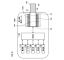
- FIG. 2 is a schematic diagram showing an example of the configuration of a portion related to charging of power supply unit 111 in suction device 100.
- thick solid lines represent electrical wiring
- solid arrows represent control signals or detection signals.
- the suction device 100 is configured to further include, in addition to the power supply unit 111, a battery temperature sensor 101, a power receiving unit 102, a charging IC 103, and an MCU 104.
- the control unit 116 described above is configured, for example, by the charging IC 103 and MCU 104 shown in FIG. 2.
- the power supply unit 111 is realized by, for example, a rechargeable battery, and is configured to be rechargeable by power received from an external power supply PS.
- the external power supply PS is a device configured to be able to output a predetermined power.
- the predetermined power is power that the suction device 100 can receive in terms of hardware, and can be, for example, DC power having a predetermined voltage (for example, 5 to 20 V).
- the external power supply PS can be, for example, an AC adapter (AC: Alternating Current) configured to be able to output the predetermined power.
- the external power supply PS is not limited to an AC adapter, and can be, for example, a mobile charger (also called a mobile battery), a PC (Personal Computer), a smartphone, or a tablet terminal.
- the power supply unit 111 is configured to be able to supply the stored power to each component of the suction device 100, such as the charging IC 103, the MCU 104, and the heating unit 121 (not shown in FIG. 2).
- FIG. 2 illustrates an example in which power is directly supplied from the power supply unit 111 to the MCU 104, this is not limiting.
- power may be supplied from the power supply unit 111 to the MCU 104 via the charging IC 103.
- the battery temperature sensor 101 is a sensor configured to be able to output a detection signal indicating a parameter related to the temperature of the power supply unit 111.
- the battery temperature sensor 101 is a thermistor arranged near the rechargeable battery that constitutes the power supply unit 111 (e.g., so as to be in contact with the rechargeable battery).
- the battery temperature sensor 101 then outputs a detection signal indicating the electrical resistance value of its own resistor to the MCU 104 as a detection signal indicating a parameter related to the temperature of the power supply unit 111.
- the battery temperature sensor 101 may also be configured to output a detection signal directly indicating the battery temperature.
- the power receiving unit 102 is configured to be capable of receiving power output from the external power source PS.
- the power receiving unit 102 can be a receptacle compatible with various standards such as USB Type-C (registered trademark), microUSB, or Lightning (registered trademark), which has a power supply terminal (e.g., a VBUS terminal) that receives power output from the external power source PS.
- the power receiving unit 102 may also be a receiving coil or the like configured to be capable of contactlessly receiving power transmitted from the external power source PS.
- the method of contactless power transfer may be an electromagnetic induction type, a magnetic resonance type, or a combination of the electromagnetic induction type and the magnetic resonance type.
- the charging IC 103 is an integrated circuit (IC) that is electrically provided between the power receiving unit 102 and the power supply unit 111 and is configured to be capable of controlling the charging of the power supply unit 111 with power received from the external power supply PS via the power receiving unit 102, and is an example of a first control unit in this disclosure.
- IC integrated circuit
- the charging IC 103 starts charging the power supply unit 111 with the power received from the external power source PS.
- the request to start charging can be, for example, the establishment of an electrical connection between the suction device 100 and the external power source PS.
- the request to start charging can also be a predetermined operation performed in a state where an electrical connection between the suction device 100 and the external power source PS has been established.
- One example of this operation can be pressing a predetermined operation button provided on the suction device 100.
- This operation is not limited to a direct operation on the suction device 100, and can also be, for example, an operation on another device such as a smartphone that can communicate with the suction device 100.
- the charging IC 103 controls, for example, the current value of the charging current (hereinafter also simply referred to as the "charging current") that charges the power supply unit 111.
- the charging IC 103 changes the value of the charging current within a predetermined range in accordance with instructions from the MCU 104, which will be described later.
- the first temperature range is a temperature range below a predetermined threshold temperature, in other words, a temperature range that is on the low side when the threshold temperature is used as a reference.
- the threshold temperature is set to 45°C
- the temperature range below 45°C is set to the first temperature range.
- the charging IC 103 when the battery temperature is included in the first temperature range, the charging IC 103 changes the value of the charging current within a range from 1500mA to 2600mA.
- the charging IC 103 sets the charging current value to a current value smaller than the lower limit of the above range (hereinafter simply referred to as the "lower limit"; in this embodiment, 1500 mA) regardless of instructions from the MCU 104.
- the second temperature range is a temperature range equal to or higher than the above threshold temperature, in other words, a temperature range that is on the higher side when the threshold temperature is used as a reference.
- the threshold temperature is 45°C, so the temperature range of 45°C or higher is the second temperature range.
- the charging IC 103 detects that the battery temperature has reached the second temperature range, it has a protective function of autonomously reducing the charging current significantly to prevent further increases in battery temperature, regardless of instructions from the MCU 104.
- the charging IC 103 may detect its own temperature and determine the battery temperature based on its own temperature. As an example, the charging IC 103 may determine the battery temperature by assuming that its own temperature is equal to the battery temperature. As another example, the charging IC 103 may determine the temperature obtained by adding, subtracting, or multiplying its own temperature by a predetermined value set in advance as the battery temperature.
- the battery temperature sensor 101 may also output a detection signal indicating a parameter related to the temperature of the power supply unit 111 to the charging IC 103.
- the charging IC 103 can obtain the battery temperature based on the detection signal received from the battery temperature sensor 101.
- the MCU 104 may output information indicating the battery temperature to the charging IC 103, and the charging IC 103 may obtain the battery temperature based on that information.
- the MCU 104 is a computer that is mainly composed of a processor that performs various calculations and controls the entire suction device 100 according to a pre-prepared program, and is an example of a second control unit in this disclosure.
- the control objects controlled by the MCU 104 include the charging IC 103.
- the MCU 104 acquires the battery temperature at a predetermined interval (e.g., every 5 ms) based on the detection signal received from the battery temperature sensor 101. If the acquired battery temperature is within the first temperature range, the MCU 104 instructs the charging IC 103 to change the current value of the charging current within a predetermined range (a range from 1500 mA to 2600 mA in this embodiment). At this time, the MCU 104 changes the current value of the charging current so that the battery temperature does not exceed a threshold temperature (45°C in this embodiment).
- a threshold temperature 45°C in this embodiment
- Fig. 3 is a diagram showing an example of charging control in the suction device 100. As shown in Fig. 3, for example, when the battery temperature is included in the first temperature range, the MCU 104 changes the current value of the charging current stepwise in accordance with the battery temperature within a range from 1500 [mA] to 2600 [mA].
- the MCU 104 sets the charging current to 2600mA, which is the upper limit of the range (hereinafter also referred to simply as "upper limit").
- the MCU 104 sets the charging current to 2400mA (see the solid arrow marked with the symbol a in Figure 3).
- the MCU 104 sets the charging current value to 2200 [mA] (see the solid arrow with symbol b1 in FIG. 3).
- the charging current value is 2400 [mA]
- the MCU 104 sets the charging current value to 2600 [mA] (see the dashed arrow with symbol b2 in FIG. 3).
- the MCU 104 sets the charging current value to 2000 mA (see the solid arrow with symbol c1 in FIG. 3).
- the charging current value is 2200 mA
- the battery temperature is greater than or equal to 40°C and less than 41°C (e.g., 40°C)
- the MCU 104 sets the charging current value to 2400 mA (see the dashed arrow with symbol c2 in FIG. 3).
- the MCU 104 sets the charging current value to 1800 mA (see the solid arrow with symbol d1 in FIG. 3).
- the MCU 104 sets the charging current value to 2200 mA (see the dashed arrow with symbol d2 in FIG. 3).
- the MCU 104 sets the charging current value to the lower limit of 1500 mA (see the solid arrow with symbol e1 in FIG. 3).
- the MCU 104 sets the charging current value to 2000 mA (see the dashed arrow with symbol e2 in FIG. 3).
- the charging IC 103 sets the charging current value to 500 mA, which is even smaller than the lower limit of 1500 mA, regardless of instructions from the MCU 104 (see the solid arrow marked with symbol f1 in Figure 3).
- the charging IC 103 may maintain the charging current at 500 mA until the current charging is completed, or may resume charging according to instructions from the MCU 104 when the battery temperature becomes less than 45° C. (e.g., 44° C.).
- the charging IC 103 may resume charging according to instructions from the MCU 104 and set the charging current value to, for example, 1500 mA.
- the MCU 104 sets the charging current to 1800 mA (see the dashed arrow marked f2 in Figure 3).
- the suction device 100 when the battery temperature reaches a temperature range near the threshold temperature at which the protective function of the charging IC 103 is activated (a temperature range of 40 to 44°C in the example shown in Figure 3), charging control is performed such that the higher the battery temperature, the lower the charging current is reduced, and the lower the battery temperature, the higher the charging current is increased.
- a temperature range near the threshold temperature at which the protective function of the charging IC 103 is activated a temperature range of 40 to 44°C in the example shown in Figure 3
- the charging IC 103 and MCU 104 can change the value of the charging current within a predetermined range according to the battery temperature when the battery temperature is in a first temperature range below the threshold temperature.
- the value of the charging current can be made even smaller than the lower limit of the predetermined range. This allows the charging current to be appropriately controlled according to the battery temperature, and makes it possible to efficiently charge the power supply unit 111 while preventing the power supply unit 111 from becoming too hot. Therefore, it is possible to achieve higher quality charging control that can shorten the charging time of the power supply unit 111 while ensuring safety.
- the MCU 104 instructs the charging IC 103 to change the current value of the charging current within a predetermined range according to the battery temperature. Then, when the battery temperature is included in the first temperature range, the charging IC 103 changes the current value of the charging current according to the instruction of the MCU 104.
- the charging IC 103 makes the current value of the charging current even smaller than the lower limit of the above-mentioned predetermined range, regardless of the instruction of the MCU 104.
- the charging IC 103 can autonomously reduce the charging current without waiting for an instruction from the MCU 104, and can quickly prevent the battery temperature from further increasing.
- the charging IC 103 and MCU 104 change the current value of the charging current according to the battery temperature so that the battery temperature does not exceed the threshold temperature. This makes it possible to prevent the battery temperature from exceeding the threshold temperature and causing the charging current to be throttled, and makes it possible to charge the power supply unit 111 efficiently.
- the charging IC 103 and MCU 104 i.e., the control unit 116) change the current value of the charging current in stages according to the battery temperature, for example, when the battery temperature is included in the first temperature range. This makes it possible to more simply and appropriately control the charging current according to the battery temperature.
- the charging IC 103 and MCU 104 i.e., the control unit 116 set the charging current to a predetermined first current value (e.g., 2200 mA), and when the battery temperature reaches a second temperature lower than the first temperature while the charging current is at the first current value, set the charging current to a second current value (e.g., 2400 mA) higher than the first current value.
- a predetermined first current value e.g., 2200 mA
- a second current value e.g., 2400 mA
- the charging IC 103 and MCU 104 i.e., control unit 116 set the charging current value to a third current value lower than the first current value. This makes it possible to change the charging current to the smaller third current value in response to an increase in battery temperature when the charging current value is set to the first current value, thereby reducing the load on the power supply unit 111 (i.e., heat generation) and suppressing further increases in battery temperature.
- the charging current is increased from 2000mA to 2200mA.
- the charging current is changed from 2200mA to another current value (e.g., 2000mA or 2400mA) when the power supply temperature reaches a temperature other than 41°C (e.g., 40°C or 42°C).
- the battery temperature (e.g., 41°C) at which the charging current is set to one current value (e.g., 2200 mA) is different from the battery temperature (e.g., 40°C or 42°C) at which the charging current is changed from the one current value to another current value.
- the battery temperature that is the condition for the charging current to be set to one current value and the battery temperature that is the condition for the charging current to be changed from that one current value to another were made equal, the charging current would be changed to one current value immediately after being set to that one current value, and then immediately after that change, it would be changed back to the one current value again, which is known as "chattering.” This could result in problems such as the charging current repeatedly increasing and decreasing. Therefore, in this embodiment, the battery temperature that is the condition for the charging current to be set to one current value and the battery temperature that is the condition for the charging current to be changed from that one current value to another current value are made different from each other, thereby preventing such problems from occurring.
- the heating unit 121 when the heating unit 121 generates aerosol, power is supplied from the power supply unit 111 to the heating unit 121 (i.e., the power supply unit 111 is discharged). Therefore, it is expected that the battery temperature will be high immediately after the heating unit 121 generates aerosol. In addition, it is expected that, for example, due to hardware constraints of the suction device 100, a time lag will occur between the start of charging and the application of the above-mentioned charging control (i.e., feedback control such as changing the charging current according to the battery temperature).
- the above-mentioned charging control i.e., feedback control such as changing the charging current according to the battery temperature.
- a situation may occur in which a large charging current (e.g., the upper limit of 2600 [mA]) flows even though the battery temperature is high immediately after aerosol generation by the heating unit 121. If such a situation occurs, the battery temperature will immediately reach the threshold temperature (e.g., 45 [°C]), and as a result, the charging current will be throttled and the charging time will be extended.
- a large charging current e.g., the upper limit of 2600 [mA]
- the threshold temperature e.g., 45 [°C]
- the charging IC 103 and the MCU 104 may set the current value of the charging current to a predetermined current value that is smaller than the upper limit value of a predetermined range for a predetermined period of time.
- the MCU 104 may instruct the charging IC 103 to set the charging current value to 1500 [mA], which is lower than the upper limit of 2600 [mA], regardless of the battery temperature, during the period from the time the request to start charging was made until 10 minutes have elapsed, as shown by the dashed dotted line marked with the symbol h in FIG. 3.
- the current value of the charging current is set to a current value smaller than the upper limit value for a specified period of time, thereby making it possible to avoid a large charging current flowing when the power supply unit 111 is hot after aerosol generation and to suppress a further increase in battery temperature. Also, in this case, by setting the current value of the charging current for the specified period to the lower limit value (1500 mA in this embodiment), it is possible to more reliably avoid a large charging current flowing when the battery temperature is high.
- the charging IC 103 and MCU 104 may change the current value of the charging current within a predetermined range according to the battery temperature. This allows the charging current to be appropriately controlled according to the battery temperature after the predetermined period has elapsed, making it possible to efficiently charge the power supply unit 111 while preventing the power supply unit 111 from becoming too hot.
- the charging IC 103 and the MCU 104 may set the current value of the charging current to a predetermined current value (e.g., the lower limit of 1500 mA) that is smaller than the upper limit for a predetermined period (e.g., 10 minutes from the time when the charging start request is made) if the battery temperature when the charging start request is made is equal to or higher than a predetermined temperature (e.g., 35°C) included in the first temperature range.
- a predetermined current value e.g., the lower limit of 1500 mA
- a predetermined period e.g. 10 minutes from the time when the charging start request is made
- a predetermined temperature e.g. 35°C
- the charging IC 103 and the MCU 104 may change the current value of the charging current within a predetermined range according to the battery temperature if the battery temperature when the above-mentioned predetermined period has elapsed is included in the first temperature range.
- the charging current is increased or decreased for battery temperatures in increments of 1°C, but this is not limited to the above.
- the charging current may be increased or decreased for battery temperatures in increments of 0.5°C, or may be increased or decreased for battery temperatures in increments of 2°C.
- FIG. 4 is a diagram showing another example of charging control in the suction device 100.
- the charging IC 103 and the MCU 104 i.e., the control unit 116 may change the current value of the charging current linearly within the above range according to the battery temperature when the battery temperature is included in the first temperature range. In this way, the charging current can be controlled more precisely and appropriately according to the battery temperature.
- Fig. 5 is a flowchart showing an example of the process performed by the MCU 104.
- the MCU 104 determines whether or not a user has made a request to start charging (step S1). If it is determined that there has been no request to start charging (step S1: NO), the MCU 104 repeats the process of step S1 until it is determined that there has been a request to start charging.
- step S1 determines whether a request to start charging has been made. If it is determined that a request to start charging has been made (step S1: YES), the MCU 104 acquires the battery temperature based on the detection signal of the battery temperature sensor 101 (step S2), and determines whether the acquired battery temperature is equal to or higher than a predetermined temperature (e.g., 35°C) (step S3). If it is determined that the battery temperature is lower than the predetermined temperature (step S3: NO), the MCU 104 proceeds directly to the processing of step S7.
- a predetermined temperature e.g. 35°C
- step S3 YES
- the MCU 104 instructs the charging IC 103 to charge the power supply unit 111 with a charging current of a predetermined current value (e.g., 1500 mA) that is smaller than the upper limit (step S4).
- a predetermined current value e.g. 1500 mA
- step S5 determines whether or not a predetermined period (e.g., 10 minutes) has elapsed. If it is determined that the predetermined period has not elapsed (step S5: NO), the MCU 104 repeats the process of step S5 until the predetermined period has elapsed.
- step S5 If it is determined that the predetermined period has elapsed (step S5: YES), the MCU 104 obtains the battery temperature based on the detection signal of the battery temperature sensor 101 (step S6), and instructs the charging IC 103 to charge the power supply unit 111 with a charging current that corresponds to the battery temperature as shown in Figures 3 and 4 (step S7).
- the MCU 104 determines whether or not to terminate charging (step S8). As one example, the MCU 104 determines to terminate charging in response to a predetermined charging termination condition being met.
- a charging termination condition is when the power supply unit 111 is in a fully charged state.
- a charging termination condition is when the electrical connection between the suction device 100 and the external power supply PS is released.
- step S8 If it is determined that charging should be terminated (step S8: YES), the MCU 104 instructs the charging IC 103 to terminate charging of the power supply unit 111 (step S9), and ends the series of processes shown in FIG. 5. On the other hand, if it is determined that charging should not be terminated (step S8: NO), the MCU 104 returns to the process of step S6 and repeats the above process.
- Fig. 6 is a flowchart showing an example of the process performed by the charging IC 103.
- the charging IC 103 determines whether the power supply unit 111 is being charged (step S21). If it is determined that the power supply unit 111 is not being charged (step S21: NO), the charging IC 103 repeats the process of step S21 until charging of the power supply unit 111 is started.
- the charging IC 103 acquires the battery temperature, for example, based on its own temperature (step S22). Also, when the battery temperature sensor 101 is configured to output a detection signal to the charging IC 103, the charging IC 103 may acquire the battery temperature based on the detection signal of the battery temperature sensor 101.
- the charging IC 103 determines whether the acquired battery temperature is below a threshold temperature (e.g., 45°C) (step S23). If it is determined that the battery temperature is below the threshold temperature (step S23: NO), that is, if it is determined that the battery temperature is within the first temperature range, the charging IC 103 charges the power supply unit 111 with a charging current having a current value according to an instruction from the MCU 104 (step S24).
- a threshold temperature e.g. 45°C
- step S23 YES
- the charging IC 103 charges the power supply unit 111 with a charging current that is even smaller than the lower limit (e.g., 500 mA) regardless of instructions from the MCU 104 (step S25).
- the charging IC 103 determines whether or not an instruction to end charging has been received from the MCU 104 (step S26). If it is determined that an instruction to end charging has been received (step S26: YES), the charging IC 103 ends charging of the power supply unit 111 (step S27) and ends the series of processes shown in FIG. 6. On the other hand, if it is determined that an instruction to end charging has not been received, the charging IC 103 returns to the process of step S22 and repeats the above process.
- the charging current can be appropriately controlled according to the battery temperature through cooperation between the charging IC 103 and the MCU 104, and the power supply unit 111 can be efficiently charged while preventing the power supply unit 111 from becoming too hot. Therefore, it is possible to achieve higher quality charging control that can shorten the charging time of the power supply unit 111 while ensuring safety.
- the control method described in the above embodiment can be realized by executing a prepared program on a computer (processor).
- This program is stored in a computer-readable storage medium and is executed by reading it from the storage medium.
- This program may be provided in a form stored in a non-transitory storage medium such as a flash memory, or provided via a network such as the Internet.
- the computer that executes this program can be, for example, one included in the suction device 100 (e.g., a CPU possessed by the suction device 100), but is not limited to this, and may also be one included in another device that can communicate with the suction device 100 (e.g., a smartphone or a server).
- a power source power source unit 111, 111A, 111B
- a control unit control units 116, 116A, 116B, charging IC 103, MCU 104 configured to acquire a temperature of the power source and control charging of the power source based on the temperature of the power source
- Equipped with The control unit is When the temperature of the power source is included in a first temperature range, which is a temperature range below a predetermined threshold temperature, a current value of a charging current for charging the power source is changed within a predetermined range according to the temperature of the power source;
- the current value of the charging current for charging the power source can be changed within a predetermined range according to the temperature of the power source.
- a second temperature range which is a temperature range equal to or higher than the threshold temperature
- the current value of the charging current can be made even smaller than the lower limit of the predetermined range.
- the control unit is When the temperature of the power source is included in the first temperature range, a current value of the charging current is changed according to the temperature of the power source so that the temperature of the power source does not exceed the threshold temperature. Power supply unit.
- the control unit is When the temperature of the power source is included in the first temperature range, the current value of the charging current is changed stepwise in accordance with the temperature of the power source. Power supply unit.
- the power supply unit according to (1) or (2), The control unit is When the temperature of the power source is included in the first temperature range, a current value of the charging current is changed linearly in response to the temperature of the power source. Power supply unit.
- the control unit is when the temperature of the power source is included in the first temperature range and the temperature of the power source reaches a predetermined first temperature, the current value of the charging current is set to a predetermined first current value; when the temperature of the power source becomes a second temperature lower than the first temperature while the current value of the charging current is the first current value, the current value of the charging current is changed to a second current value higher than the first current value. Power supply unit.
- the charging current when the charging current is set to a first current value, the charging current can be changed to a larger second current value in response to a drop in the temperature of the power source, making it possible to charge the power source efficiently.
- the power supply unit is when the temperature of the power source reaches a third temperature higher than the first temperature while the current value of the charging current is the first current value, the current value of the charging current is set to a third current value lower than the first current value. Power supply unit.
- the charging current when the charging current has a first current value and the temperature of the power source rises, the charging current can be changed to a smaller third current value, thereby reducing the load on the power source (i.e., heat generation) and preventing a further rise in the temperature of the power source.
- the charging current would be changed to one current value immediately after being changed to another current value, and then immediately returned to the one current value, causing so-called "chattering" and resulting in an inconvenience such as an endless repetition of increases and decreases in the charging current.
- the temperature of the power source that sets the charging current to one current value and the temperature of the power source that sets the charging current to another current value are different, making it possible to prevent such inconveniences from occurring.
- the power supply unit according to any one of (1) to (7), The control unit is When a request to start charging is made after the aerosol is generated, the current value of the charging current is set to a predetermined current value that is smaller than an upper limit value of the predetermined range for a predetermined period of time. Power supply unit.
- the heating unit When the heating unit generates aerosol, power is supplied from the power source to the heating unit, so it is expected that the temperature of the power source will be high after the aerosol is generated.
- the current value of the charging current is set to a predetermined current value that is smaller than the upper limit of a predetermined range for a predetermined period of time. This makes it possible to avoid a large charging current flowing when the power source is hot after the aerosol is generated, and to suppress further increases in the temperature of the power source.
- the control unit is When a temperature of the power source at the time when a request to start charging is made is equal to or higher than a predetermined temperature included in the first temperature range, a current value of the charging current is set to a predetermined current value that is smaller than an upper limit value of the predetermined range for a predetermined period of time. Power supply unit.
- the current value of the charging current is set to a predetermined current value that is smaller than the upper limit of the predetermined range for a predetermined period of time. This makes it possible to prevent a large charging current from flowing when the power source is hot and to suppress further increases in the temperature of the power source.
- the power supply unit according to (8) or (9),
- the predetermined current value is the lower limit value. Power supply unit.
- the power supply unit according to any one of (8) to (10), The control unit is When the temperature of the power source after the predetermined period has elapsed is within the first temperature range, a current value of the charging current is changed within the predetermined range in accordance with the temperature of the power source. Power supply unit.
- the current value of the charging current is changed within a predetermined range according to the temperature of the power source.
- the power supply unit according to any one of (1) to (11),
- the control unit is A first control unit (charging IC 103) configured to be able to control charging of the power source;
- a second control unit (MCU 104) configured to be able to control the first control unit based on the temperature of the power source;
- the present invention relates to a method for manufacturing a computer-implemented ...
- the second control unit is when the temperature of the power source is included in the first temperature range, instructing the first control unit to change a current value of the charging current within the predetermined range in response to the temperature of the power source;
- the first control unit is When the temperature of the power source is included in the first temperature range, a current value of the charging current is changed in accordance with an instruction from the second control unit; When the temperature of the power source is included in the second temperature range, the current value of the charging current is made smaller than the lower limit value of the predetermined range regardless of an instruction from the second control unit. Power supply unit.
- the second control unit instructs the first control unit to change the current value of the charging current within a predetermined range according to the temperature of the power source. Then, the first control unit changes the current value of the charging current according to the instruction of the second control unit.
- the first control unit makes the current value of the charging current even smaller than the lower limit of the predetermined range, regardless of the instruction of the second control unit.
- the first control unit can autonomously reduce the charging current without waiting for an instruction from the second control unit, and can quickly prevent the temperature of the power source from further increasing. Therefore, it is possible to prevent the power source from becoming too hot and perform charging with consideration for safety.
- the power supply unit further includes a power receiving unit that receives power output from the external power supply
- the first control unit is a charging IC (Integrated Circuit) (charging IC 103) provided between the power receiving unit and the power source
- the second control unit is a Micro Controller Unit (MCU) (MCU104) that controls the power supply unit. Power supply unit.
- MCU Micro Controller Unit
- the charging current can be appropriately controlled according to the temperature of the power source, and it is possible to charge the power source efficiently while preventing the power source from becoming too hot.
- a control method performed by a computer that controls a power supply unit (inhalation device 100, 100A, 100B, power supply unit 110) of an aerosol generating device (inhalation device 100, 100A, 100B) that generates an aerosol by heating an aerosol source, comprising:
- the power supply unit includes a power supply (power supply unit 111, 111A, 111B) configured to be capable of supplying power to a heating unit (heating unit 121, 121A, 121B) that heats the aerosol source and to be chargeable by power received from an external power supply (external power supply PS), the computer is configured to acquire a temperature of the power source and control charging of the power source based on the temperature of the power source;
- the computer When the temperature of the power source is included in a first temperature range, which is a temperature range below a predetermined threshold temperature, a current value of a charging current for charging the power source is changed within
- the current value of the charging current for charging the power source can be changed within a predetermined range according to the temperature of the power source.
- a second temperature range which is a temperature range equal to or higher than the threshold temperature
- the current value of the charging current can be made even smaller than the lower limit of the predetermined range.
- a control program for causing a computer (control unit 116, 116A, 116B, charging IC 103, MCU 104) that controls a power supply unit (inhalation device 100, 100A, 100B, power supply unit 110) of an aerosol generating device (inhalation device 100, 100A, 100B) that generates an aerosol by heating an aerosol source to perform a predetermined process
- the power supply unit includes a power supply (power supply unit 111, 111A, 111B) configured to be capable of supplying power to a heating unit (heating unit 121, 121A, 121B) that heats the aerosol source and to be chargeable by power received from an external power supply (external power supply PS), the computer is configured to acquire a temperature of the power source and control charging of the power source based on the temperature of the power source;
- the computer includes: When the temperature of the power source is included in a first temperature range, which is a temperature range below a predetermined threshold temperature, a current value of a charging current
- the current value of the charging current for charging the power source can be changed within a predetermined range according to the temperature of the power source.
- a second temperature range which is a temperature range equal to or higher than the threshold temperature
- the current value of the charging current can be made even smaller than the lower limit of the predetermined range.
- Suction device (aerosol generating device, power supply unit) 110 Power supply unit 111, 111A, 111B Power supply unit (power supply) 121, 121A, 121B Heating unit 116, 116A, 116B Control unit (computer) 102 Power receiving unit 103 Charging IC (control unit, first control unit) 104 MCU (control unit, second control unit) PS External power supply
Landscapes
- Engineering & Computer Science (AREA)
- Power Engineering (AREA)
- Charge And Discharge Circuits For Batteries Or The Like (AREA)
Priority Applications (5)
| Application Number | Priority Date | Filing Date | Title |
|---|---|---|---|
| PCT/JP2023/007123 WO2024180625A1 (ja) | 2023-02-27 | 2023-02-27 | エアロゾル生成装置の電源ユニット、制御方法、及び制御プログラム |
| EP23925183.8A EP4674297A1 (en) | 2023-02-27 | 2023-02-27 | Power supply unit for aerosol-generating device, control method, and control program |
| KR1020257025506A KR20250131793A (ko) | 2023-02-27 | 2023-02-27 | 에어로졸 생성 장치용 전력 공급 유닛, 제어 방법, 및 제어 프로그램 |
| JP2025503258A JPWO2024180625A1 (https=) | 2023-02-27 | 2023-02-27 | |
| CN202380093403.2A CN120603512A (zh) | 2023-02-27 | 2023-02-27 | 用于气溶胶产生装置的供电单元、控制方法以及控制程序 |
Applications Claiming Priority (1)
| Application Number | Priority Date | Filing Date | Title |
|---|---|---|---|
| PCT/JP2023/007123 WO2024180625A1 (ja) | 2023-02-27 | 2023-02-27 | エアロゾル生成装置の電源ユニット、制御方法、及び制御プログラム |
Publications (1)
| Publication Number | Publication Date |
|---|---|
| WO2024180625A1 true WO2024180625A1 (ja) | 2024-09-06 |
Family
ID=92589463
Family Applications (1)
| Application Number | Title | Priority Date | Filing Date |
|---|---|---|---|
| PCT/JP2023/007123 Ceased WO2024180625A1 (ja) | 2023-02-27 | 2023-02-27 | エアロゾル生成装置の電源ユニット、制御方法、及び制御プログラム |
Country Status (5)
| Country | Link |
|---|---|
| EP (1) | EP4674297A1 (https=) |
| JP (1) | JPWO2024180625A1 (https=) |
| KR (1) | KR20250131793A (https=) |
| CN (1) | CN120603512A (https=) |
| WO (1) | WO2024180625A1 (https=) |
Citations (5)
| Publication number | Priority date | Publication date | Assignee | Title |
|---|---|---|---|---|
| JP2008228492A (ja) * | 2007-03-14 | 2008-09-25 | Sanyo Electric Co Ltd | リチウムイオン二次電池の充電方法 |
| JP2009219221A (ja) * | 2008-03-10 | 2009-09-24 | Panasonic Corp | 充電装置 |
| JP2017518733A (ja) | 2014-04-30 | 2017-07-13 | フィリップ・モーリス・プロダクツ・ソシエテ・アノニム | 電気加熱式エアロゾル発生システム |
| JP2020114199A (ja) * | 2019-01-17 | 2020-07-30 | 日本たばこ産業株式会社 | エアロゾル吸引器用の電源ユニット、エアロゾル吸引器用の電源ユニットの制御方法及びプログラム |
| JP6934114B2 (ja) | 2018-08-13 | 2021-09-08 | 日本たばこ産業株式会社 | 香味生成システム、方法及びプログラム |
-
2023
- 2023-02-27 KR KR1020257025506A patent/KR20250131793A/ko active Pending
- 2023-02-27 WO PCT/JP2023/007123 patent/WO2024180625A1/ja not_active Ceased
- 2023-02-27 CN CN202380093403.2A patent/CN120603512A/zh active Pending
- 2023-02-27 EP EP23925183.8A patent/EP4674297A1/en active Pending
- 2023-02-27 JP JP2025503258A patent/JPWO2024180625A1/ja active Pending
Patent Citations (5)
| Publication number | Priority date | Publication date | Assignee | Title |
|---|---|---|---|---|
| JP2008228492A (ja) * | 2007-03-14 | 2008-09-25 | Sanyo Electric Co Ltd | リチウムイオン二次電池の充電方法 |
| JP2009219221A (ja) * | 2008-03-10 | 2009-09-24 | Panasonic Corp | 充電装置 |
| JP2017518733A (ja) | 2014-04-30 | 2017-07-13 | フィリップ・モーリス・プロダクツ・ソシエテ・アノニム | 電気加熱式エアロゾル発生システム |
| JP6934114B2 (ja) | 2018-08-13 | 2021-09-08 | 日本たばこ産業株式会社 | 香味生成システム、方法及びプログラム |
| JP2020114199A (ja) * | 2019-01-17 | 2020-07-30 | 日本たばこ産業株式会社 | エアロゾル吸引器用の電源ユニット、エアロゾル吸引器用の電源ユニットの制御方法及びプログラム |
Also Published As
| Publication number | Publication date |
|---|---|
| KR20250131793A (ko) | 2025-09-03 |
| JPWO2024180625A1 (https=) | 2024-09-06 |
| CN120603512A (zh) | 2025-09-05 |
| EP4674297A1 (en) | 2026-01-07 |
Similar Documents
| Publication | Publication Date | Title |
|---|---|---|
| US20230000172A1 (en) | Inhaling device | |
| US20230000152A1 (en) | Inhaling device, control method, and non-transitory computer readable medium | |
| US20240277075A1 (en) | Notification control device, notification control method, and storage medium | |
| JP7802094B2 (ja) | エアロゾル生成装置の回路ユニット、エアロゾル生成装置及びプログラム | |
| JP2026032291A (ja) | エアロゾル生成装置の回路ユニット、エアロゾル生成装置及びプログラム | |
| WO2024180625A1 (ja) | エアロゾル生成装置の電源ユニット、制御方法、及び制御プログラム | |
| EP4674298A1 (en) | Power supply unit of aerosol generation device, control method, and control program | |
| JP7610952B2 (ja) | 吸引装置の制御ユニット及び吸引装置の制御方法 | |
| EP4434374A1 (en) | Suction device | |
| EP4666892A1 (en) | Power supply unit for aerosol generation device and control method | |
| EP4434376A1 (en) | Inhalation device | |
| WO2023007525A1 (ja) | エアロゾル生成システム | |
| EP4635344A1 (en) | Power supply unit for inhalation device, control method, and control program | |
| EP4691299A1 (en) | Power source unit for aerosol generation device, and aerosol generation device | |
| EP4635349A1 (en) | Inhalation device control method, inhalation device power supply unit, and program for inhalation device | |
| EP4635348A1 (en) | Control method for inhalation device, power source unit for inhalation device, and program for inhalation device | |
| EP4563024A1 (en) | Aerosol generation system, control method, and program | |
| EP4427615A1 (en) | Aerosol generation system, control method, and program | |
| WO2025126400A1 (ja) | エアロゾル生成装置 | |
| WO2024257274A1 (ja) | エアロゾル生成装置の電源ユニット | |
| WO2024171266A1 (ja) | エアロゾル生成装置の電源ユニット、及び、エアロゾル生成装置 | |
| WO2022190211A1 (ja) | 吸引装置、及びプログラム | |
| WO2025154266A1 (ja) | 加熱情報設定方法、加熱情報設定システム、及びプログラム | |
| WO2025126388A1 (ja) | エアロゾル生成装置の電源ユニット | |
| KR20250114063A (ko) | 향미 흡입기 또는 에어로졸-생성 장치, 및 이의 동작 방법 및 프로그램 |
Legal Events
| Date | Code | Title | Description |
|---|---|---|---|
| 121 | Ep: the epo has been informed by wipo that ep was designated in this application |
Ref document number: 23925183 Country of ref document: EP Kind code of ref document: A1 |
|
| ENP | Entry into the national phase |
Ref document number: 1020257025506 Country of ref document: KR Free format text: ST27 STATUS EVENT CODE: A-0-1-A10-A15-NAP-PA0105 (AS PROVIDED BY THE NATIONAL OFFICE) |
|
| WWE | Wipo information: entry into national phase |
Ref document number: 202380093403.2 Country of ref document: CN |
|
| ENP | Entry into the national phase |
Ref document number: 2025503258 Country of ref document: JP Kind code of ref document: A |
|
| WWE | Wipo information: entry into national phase |
Ref document number: 2025503258 Country of ref document: JP |
|
| WWP | Wipo information: published in national office |
Ref document number: 202380093403.2 Country of ref document: CN |
|
| WWE | Wipo information: entry into national phase |
Ref document number: 2023925183 Country of ref document: EP |
|
| NENP | Non-entry into the national phase |
Ref country code: DE |
|
| ENP | Entry into the national phase |
Ref document number: 2023925183 Country of ref document: EP Effective date: 20250929 |
|
| ENP | Entry into the national phase |
Ref document number: 2023925183 Country of ref document: EP Effective date: 20250929 |
|
| ENP | Entry into the national phase |
Ref document number: 2023925183 Country of ref document: EP Effective date: 20250929 |
|
| WWP | Wipo information: published in national office |
Ref document number: 2023925183 Country of ref document: EP |