WO2024176749A1 - 情報処理装置、立体映像表示システム及びプログラム - Google Patents
情報処理装置、立体映像表示システム及びプログラム Download PDFInfo
- Publication number
- WO2024176749A1 WO2024176749A1 PCT/JP2024/002742 JP2024002742W WO2024176749A1 WO 2024176749 A1 WO2024176749 A1 WO 2024176749A1 JP 2024002742 W JP2024002742 W JP 2024002742W WO 2024176749 A1 WO2024176749 A1 WO 2024176749A1
- Authority
- WO
- WIPO (PCT)
- Prior art keywords
- image
- stereoscopic
- display
- user
- eye
- Prior art date
- Legal status (The legal status is an assumption and is not a legal conclusion. Google has not performed a legal analysis and makes no representation as to the accuracy of the status listed.)
- Ceased
Links
Images









Classifications
-
- G—PHYSICS
- G06—COMPUTING OR CALCULATING; COUNTING
- G06T—IMAGE DATA PROCESSING OR GENERATION, IN GENERAL
- G06T19/00—Manipulating three-dimensional [3D] models or images for computer graphics
-
- G—PHYSICS
- G09—EDUCATION; CRYPTOGRAPHY; DISPLAY; ADVERTISING; SEALS
- G09G—ARRANGEMENTS OR CIRCUITS FOR CONTROL OF INDICATING DEVICES USING STATIC MEANS TO PRESENT VARIABLE INFORMATION
- G09G5/00—Control arrangements or circuits for visual indicators common to cathode-ray tube indicators and other visual indicators
-
- G—PHYSICS
- G09—EDUCATION; CRYPTOGRAPHY; DISPLAY; ADVERTISING; SEALS
- G09G—ARRANGEMENTS OR CIRCUITS FOR CONTROL OF INDICATING DEVICES USING STATIC MEANS TO PRESENT VARIABLE INFORMATION
- G09G5/00—Control arrangements or circuits for visual indicators common to cathode-ray tube indicators and other visual indicators
- G09G5/36—Control arrangements or circuits for visual indicators common to cathode-ray tube indicators and other visual indicators characterised by the display of a graphic pattern, e.g. using an all-points-addressable [APA] memory
-
- G—PHYSICS
- G09—EDUCATION; CRYPTOGRAPHY; DISPLAY; ADVERTISING; SEALS
- G09G—ARRANGEMENTS OR CIRCUITS FOR CONTROL OF INDICATING DEVICES USING STATIC MEANS TO PRESENT VARIABLE INFORMATION
- G09G5/00—Control arrangements or circuits for visual indicators common to cathode-ray tube indicators and other visual indicators
- G09G5/36—Control arrangements or circuits for visual indicators common to cathode-ray tube indicators and other visual indicators characterised by the display of a graphic pattern, e.g. using an all-points-addressable [APA] memory
- G09G5/38—Control arrangements or circuits for visual indicators common to cathode-ray tube indicators and other visual indicators characterised by the display of a graphic pattern, e.g. using an all-points-addressable [APA] memory with means for controlling the display position
-
- H—ELECTRICITY
- H04—ELECTRIC COMMUNICATION TECHNIQUE
- H04N—PICTORIAL COMMUNICATION, e.g. TELEVISION
- H04N13/00—Stereoscopic video systems; Multi-view video systems; Details thereof
- H04N13/10—Processing, recording or transmission of stereoscopic or multi-view image signals
- H04N13/106—Processing image signals
- H04N13/122—Improving the three-dimensional [3D] impression of stereoscopic images by modifying image signal contents, e.g. by filtering or adding monoscopic depth cues
- H04N13/125—Improving the three-dimensional [3D] impression of stereoscopic images by modifying image signal contents, e.g. by filtering or adding monoscopic depth cues for crosstalk reduction
-
- H—ELECTRICITY
- H04—ELECTRIC COMMUNICATION TECHNIQUE
- H04N—PICTORIAL COMMUNICATION, e.g. TELEVISION
- H04N13/00—Stereoscopic video systems; Multi-view video systems; Details thereof
- H04N13/20—Image signal generators
- H04N13/296—Synchronisation thereof; Control thereof
-
- H—ELECTRICITY
- H04—ELECTRIC COMMUNICATION TECHNIQUE
- H04N—PICTORIAL COMMUNICATION, e.g. TELEVISION
- H04N13/00—Stereoscopic video systems; Multi-view video systems; Details thereof
- H04N13/30—Image reproducers
- H04N13/366—Image reproducers using viewer tracking
Definitions
- This technology relates to an information processing device, a stereoscopic image display system, and a program for a light field display.
- An eye-tracking light field display detects the position of the user's eyes facing the display from the camera image, and generates a two-viewpoint image (one image for the left eye and one image for the right eye) that corresponds to the position of both eyes based on the eye position.
- a stereoscopic display image is generated based on the eye position and the two-viewpoint image to distribute the two-viewpoint image to the positions of both eyes, and is displayed on the display.
- the user can view a 3D model in stereoscopic view with the naked eye by viewing each of the two-viewpoint images with their right and left eyes.
- Crosstalk is a phenomenon in which, when the eye position moves at high speed, the generation of a stereoscopic display image cannot keep up with the movement of the eye position, resulting in bleeding of images from both eyes' viewpoints (the image for the left eye is seen by the right eye, and the image for the right eye is seen by the left eye).
- Patent Documents 1 and 2 disclose stereoscopic image display devices that predict the movement of the eye position and reflect the prediction results in the stereoscopic display image.
- the objective of this technology is to provide an information processing device, a 3D image display system, and a program that can prevent crosstalk while suppressing image blur.
- an information processing device includes a position detection unit, a viewpoint video generation unit, and a stereoscopic display video generation unit.
- the position detection unit detects a detection position that is a position of a user's eyes facing a display capable of displaying stereoscopic images.
- the viewpoint video generation unit generates viewpoint videos of a three-dimensional model viewed from each of the right eye and the left eye according to a first position which is the position of the user's eyes based on the detected positions.
- the stereoscopic display image generating unit converts the viewpoint image into a stereoscopic display image that is displayed stereoscopically on the display according to a second position, which is the position of the user's eyes based on the detected positions and is different from the first position.
- the second position may be a position farther away from the detection position than the first position.
- the information processing device further includes a movement prediction unit that predicts an eye movement of the user based on the detected positions and estimates a predicted position of the eye; the first position is the detection position, The second location may be the predicted location.
- the information processing device includes: a first movement prediction unit that predicts an eye movement of the user using a first correction coefficient based on the detected positions, and estimates a first predicted position that is a predicted eye position; a second movement prediction unit that predicts a movement of the user's eyes based on the detected positions by using a second correction coefficient that is greater than the first correction coefficient, and estimates a second predicted position that is a predicted eye position; the first location is the first predicted location, The second location may be the second predicted location.
- the movement prediction unit may offset the predicted position in the acceleration direction of the detected position.
- the second movement prediction unit may offset the second predicted position in the acceleration direction of the detected position.
- the first movement prediction unit may change the first correction coefficient depending on the content including the three-dimensional model.
- the stereoscopic display image generating unit may synchronize the timing of generating the stereoscopic display image with the timing of outputting the stereoscopic display image to the display.
- a stereoscopic image display system includes a display, a camera, a position detection unit, a viewpoint image generation unit, and a stereoscopic display image generation unit.
- the display is capable of displaying stereoscopic images.
- the camera captures an image of the user's face facing the display.
- the position detection unit detects a detection position, which is the position of the user's eyes facing the display, from the image captured by the camera.
- the viewpoint video generation unit generates viewpoint videos of a three-dimensional model viewed from each of the right eye and the left eye according to a first position which is the position of the user's eyes based on the detected positions.
- the stereoscopic display image generating unit converts the viewpoint image into a stereoscopic display image that is displayed stereoscopically on the display according to a second position, which is the position of the user's eyes based on the detected positions and is different from the first position.
- a program causes an information processing device to operate as a position detection unit, a viewpoint video generation unit, and a stereoscopic display video generation unit.
- the position detection unit detects a detection position that is a position of a user's eyes facing a display capable of displaying stereoscopic images.
- the viewpoint video generation unit generates viewpoint videos of a three-dimensional model viewed from each of the right eye and the left eye according to a first position which is the position of the user's eyes based on the detected positions.
- the stereoscopic display image generating unit converts the viewpoint image into a stereoscopic display image that is displayed stereoscopically on the display according to a second position, which is the position of the user's eyes based on the detected positions and is different from the first position.
- FIG. 1 is a schematic diagram of a stereoscopic image display system according to a first embodiment of the present technology.
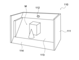
- 2 is a perspective view of a stereoscopic image display device included in the stereoscopic image display system.
- FIG. 3A and 3B are schematic diagrams showing viewpoint images in the stereoscopic image display device.
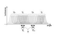
- 2 is a schematic diagram showing viewpoints in the stereoscopic image display device.
- FIG. 3A and 3B are schematic diagrams illustrating the display of stereoscopic images in the stereoscopic image display device.
- 4 is a schematic diagram showing a process for movement of a viewpoint in the stereoscopic image display device.
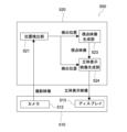
- FIG. 2 is a block diagram showing a configuration of an information processing device included in the stereoscopic image display system.
- FIG. 1 is a block diagram showing a configuration of an information processing device provided in a stereoscopic image display system having a conventional structure.
- 4 is a graph showing crosstalk in the stereoscopic image display system.
- FIG. 11 is a block diagram showing a configuration of an information processing device provided in another stereoscopic image display system with a conventional structure.
- 4 is a graph showing crosstalk in the stereoscopic image display system.
- 4 is a schematic diagram showing a margin in a stereoscopic display image of the stereoscopic image display system according to the first embodiment of the present technology.
- FIG. 10 is a schematic diagram showing offsets of predicted positions in the stereoscopic image display system.
- FIG. 10 is a schematic diagram showing offsets of predicted positions in the stereoscopic image display system.
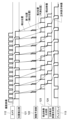
- FIG. 1 is a timing chart (without synchronization) in a stereoscopic image display system having a conventional structure.
- 4 is a timing chart (with synchronization) in the stereoscopic image display system.
- 4 is a timing chart (without synchronization) in the stereoscopic image display system according to the first embodiment of the present technology.
- 4 is a timing chart (with synchronization) in the stereoscopic image display system.
- FIG. 11 is a schematic diagram of a stereoscopic image display system according to a second embodiment of the present technology.
- 2 is a block diagram showing a configuration of an information processing device included in the stereoscopic image display system.
- FIG. 4 is a timing chart (without synchronization) in the stereoscopic image display system.
- 4 is a timing chart (with synchronization) in the stereoscopic image display system.
- FIG. 1 is a schematic diagram showing a hardware configuration of an information processing device according to a first embodiment and a second embodiment of the present
- FIG. 1 is a schematic diagram showing a configuration of a stereoscopic image display system 100 according to this embodiment.
- the stereoscopic image display system 100 includes a stereoscopic image display device 110 and an information processing device 120.
- the stereoscopic image display device 110 and the information processing device 120 are connected by wire or wirelessly, and may be connected via an information communication network.
- the information processing device 120 may be configured integrally with the stereoscopic image display device 110.
- [Configuration of stereoscopic image display device] 2 is a perspective view of the stereoscopic image display device 110.
- the stereoscopic image display device 110 is a display device called a light field display that performs stereoscopic display of the 3D model M, and displays a stereoscopic display image that is dynamically generated according to the position of the user's viewpoint.
- the stereoscopic display image is composed of viewpoint images of the 3D model M viewed from the right eye and the left eye, respectively.
- the viewpoint image includes a left eye image VL and a right eye image VR .
- the left eye image VL is an image of the 3D model M viewed from the position of the left eye E L
- the right eye image VR is an image of the 3D model M viewed from the position of the right eye E R.
- the stereoscopic image display device 110 displays the left eye image VL toward the left eye of the user and the right eye image VR toward the right eye of the user, thereby enabling stereoscopic viewing of the 3D model M with the naked eye.
- the stereoscopic image display device 110 includes a housing 111, a camera 112, and a display 113.
- the housing 111 is a housing that houses each part of the stereoscopic image display device, and has an inclined surface 114.
- the inclined surface 114 is configured to be inclined with respect to the placement surface on which the stereoscopic image display device 110 is placed.
- the camera 112 and the display 113 are arranged on the inclined surface 114.
- Camera 112 photographs the face of a user looking at display 113.
- Camera 112 is appropriately positioned at a position where it can photograph the user's face, for example, at a position above the center of display 113 on inclined surface 114.
- a digital camera equipped with an image sensor such as a CMOS (Complementary Metal-Oxide Semiconductor) sensor or a CCD (Charge Coupled Device) sensor is used.
- the specific configuration of camera 112 is not limited.
- the display 113 displays a stereoscopic image.
- the display 113 is, for example, rectangular in plan view, and is disposed on an inclined surface 114. That is, the display 113 is disposed in an inclined state when viewed from the user. This allows the user to view the 3D model M even when viewing the display 113 from, for example, the horizontal or vertical direction.
- FIG. 4 is a schematic diagram of the display 113.
- the display 113 includes a display panel 115 and a lenticular lens 116.
- the display panel 115 is a panel that displays a stereoscopic image, and may be a liquid crystal panel, an organic EL (Electro-Luminescence) panel, or the like.
- Lenticular lens 116 is attached to the surface of display panel 115 and is a lens that refracts light incident from display panel 115 in a specific direction.
- Lenticular lens 116 has a structure in which semi-cylindrical convex lenses are arranged adjacent to each other. As shown in FIG. 4, light emitted from each pixel G of display panel 115 is spatially distributed by passing through lenticular lens 116, and the user sees different images depending on the angle at which display 113 is viewed (hereinafter, viewing angle).
- FIG. 4 shows six viewpoints with different viewing angles (angle in the figure) and the luminance of each pixel according to the viewing angle (luminance in the figure).
- the number of viewpoints is not limited to six and can be any number.
- FIG. 5 is a schematic diagram showing the allocation of viewpoint images by the lenticular lens 116. As shown in the figure, when a left-eye image VL is displayed at a pixel G L and a right-eye image V R is displayed at a pixel G R according to the positions of the left eye E L and the right eye E R, only the left-eye image V L is viewed at the left eye E L and only the right-eye image V R is viewed at the right eye E R. This allows the user to stereoscopically view the three-dimensional model M on the display 113 as shown in FIG. 2.
- FIG. 6 is a schematic diagram showing the process of moving the positions of the left eye EL and the right eye ER .
- FIG. 6(a) shows a state in which the left eye EL sees the left eye image VL , and the right eye ER sees the right eye image VR .
- FIG. 6(b) when the positions of the left eye EL and the right eye ER move, the pixels G that become pixels GL and GR are changed, and the viewing angles of the left eye image VL and the right eye image VR are changed.
- the left eye EL and the right eye ER move, the left eye EL can see the left eye image VL , and the right eye ER can see the right eye image VR .
- crosstalk occurs in which the left eye E L sees the right-eye image V R and the right eye E R sees the left-eye image V L , resulting in degradation of image quality and difficulty in stereoscopically viewing the 3D model M.
- the occurrence of crosstalk is prevented as described below.
- the stereoscopic image display device 110 is not limited to a lenticular lens type using the lenticular lens 116, but may be a parallax barrier type in which a slit-shaped shielding plate is provided in front of the display 113 to separate the light entering each eye.
- [Configuration of information processing device] 7 is a block diagram showing the configuration of the information processing device 120.
- the information processing device 120 includes a position detection unit 121, a movement prediction unit 122, a viewpoint video generation unit 123, and a stereoscopic display video generation unit 124. These configurations are functional configurations realized by cooperation between hardware and software.
- the position detection unit 121 detects the position of the user's eyes facing the display 113 in real time from the image captured by the camera 112 (hereinafter, the captured image).
- the position of the user's eyes detected by the position detection unit 121 is referred to as the "detected position”.
- eye position includes both the right eye position and the left eye position.
- the position detection unit 121 can recognize the user's eyes and detect the detected position using face recognition technology on the captured image.
- the position detection unit 121 supplies the detected position to the movement prediction unit 122 and the viewpoint video generation unit 123.
- the detected position supplied by the position detection unit 121 to the viewpoint video generation unit 123 is referred to as the "first position”.
- the movement prediction unit 122 predicts the movement of the user's eyes based on the detected position, and estimates the position of the eyes after a predetermined time.
- the eye position estimated by the movement prediction unit 122 is referred to as the "predicted position”.
- the movement prediction unit 122 can estimate the predicted position by multiplying the movement speed of the detected position by a correction coefficient.
- the movement prediction unit 122 may change the correction coefficient according to the movement speed of the detected position, for example, multiplying by a large correction coefficient when the movement speed of the detected position is fast, and multiplying by a small correction coefficient when the movement speed is slow.
- the predicted position supplied by the movement prediction unit 122 to the stereoscopic display image generation unit 124 is referred to as the "second position".
- the first position is the detected position
- the second position is a predicted position based on the detected position, so the second position is a position different from the first position and is a position farther away from the detected position than the first position.
- the viewpoint image generating unit 123 generates a viewpoint image according to the first position.
- the viewpoint image generating unit 123 acquires the 3D model M by reading from a storage device or by communication. Furthermore, the viewpoint image generating unit 123 renders the 3D model M and generates a viewpoint image including a left eye image V L which is an image of the 3D model M seen from the position of the left eye E L and a right eye image V R which is an image of the 3D model M seen from the position of the right eye E R , as shown in FIG. 3.
- the viewpoint image generating unit 123 uses the first position as the position of the left eye E L and the right eye E R.
- the first position is a detected position, that is, the position of the user's eyes detected by the position detection unit 121.
- the viewpoint image generating unit 123 supplies the generated viewpoint image to the stereoscopic display image generating unit 124.
- the stereoscopic display image generating unit 124 converts the viewpoint image into a stereoscopic display image according to the second position. As shown in FIG. 5, the stereoscopic display image generating unit 124 arranges the left eye image VL and the right eye image VR according to the positions of the left eye E L and the right eye E R to generate a stereoscopic display image. At this time, the stereoscopic display image generating unit 124 uses the second position as the positions of the left eye E L and the right eye E R. As described above, the second position is a predicted position, that is, the position of the user's eyes whose movement is predicted by the movement prediction unit 122. The stereoscopic display image generating unit 124 supplies the generated stereoscopic display image to the display 113 and displays it on the display 113.
- the user can view the left-eye image VL with the left eye E L and the right-eye image V R with the right eye E R , enabling the user to view the three-dimensional model M in stereoscopic view on the display 113.
- the position detection unit 121 detects a new detected position and sets it as a first position
- the movement prediction unit 122 estimates a new predicted position and sets it as a second position.
- the viewpoint image generation unit 123 and the stereoscopic display image generation unit 124 generate stereoscopic display images according to these positions.
- the information processing device 120 has the above-described configuration. Some or all of the components of the information processing device 120 may be built into the stereoscopic image display device 110.
- FIG. 8 is a block diagram showing the configuration of a stereoscopic image display system 500 having a conventional structure.
- the stereoscopic image display system 500 includes a stereoscopic image display device 510 and an information processing device 520.
- the stereoscopic image display device 510 includes a camera 512 and a display 513.
- the information processing device 520 includes a position detection unit 521, a viewpoint image generation unit 523, and a stereoscopic display image generation unit 524.
- position detection unit 521 detects the detection position, which is the position of the user's eyes, and supplies the detection position to viewpoint image generation unit 523 and stereoscopic display image generation unit 524.
- Viewpoint image generation unit 523 generates a viewpoint image (see Figure 3) based on the detection position, and supplies the viewpoint image to stereoscopic display image generation unit 524.
- Stereoscopic display image generation unit 524 converts the viewpoint image into a stereoscopic display image (see Figure 5) based on the detection position, and displays the stereoscopic display image on display 513.
- Figure 9 is a graph showing the measurement results of eye movement speed and crosstalk fluctuation in the stereoscopic image display system 500.
- “R ⁇ L” is the case where the face is moved from right to left
- “L ⁇ R” is the case where the face is moved from left to right.
- “left”, “middle”, and “right” are the positions when the display is divided into three parts. As shown in the figure, the faster the eye movement speed, the greater the crosstalk.
- FIG. 10 is a block diagram showing the configuration of a stereoscopic image display system 600 having another conventional structure.
- the stereoscopic image display system 600 comprises a stereoscopic image display device 610 and an information processing device 620.
- the stereoscopic image display device 610 comprises a camera 612 and a display 613.
- the information processing device 620 comprises a position detection unit 621, a movement prediction unit 622, a viewpoint image generation unit 623, and a stereoscopic display image generation unit 624.
- the position detection unit 621 detects the detection position, which is the position of the user's eyes, and supplies the detection position to the movement prediction unit 622.
- the movement prediction unit 622 predicts the movement of the eyes based on the detection position, and supplies the predicted position to the viewpoint image generation unit 623 and the stereoscopic display image generation unit 624.
- the viewpoint image generation unit 623 generates a viewpoint image (see Figure 3) based on the predicted position, and supplies the viewpoint image to the stereoscopic display image generation unit 624.
- the stereoscopic display image generation unit 624 converts the viewpoint image into a stereoscopic display image (see Figure 5) based on the predicted position, and displays the stereoscopic display image on the display 613.
- the stereoscopic display image generator 624 generates a stereoscopic display image based on the predicted position, so crosstalk is suppressed.
- FIG. 11 is a graph showing the measurement results of eye movement speed and crosstalk fluctuation in the stereoscopic image display system 600. The legend is the same as in FIG. 9.
- the movement prediction unit 622 cannot keep up with sudden speed changes in the eye position, and a damping phenomenon occurs in which the deviation undulates.
- blurring occurs in the viewpoint image generated by the viewpoint image generator 623, and blurring also occurs in the stereoscopic display image generated based on that.
- the viewpoint image generation unit 123 generates a viewpoint image according to the first position
- the stereoscopic display image generation unit 124 converts the viewpoint image into a stereoscopic display image according to the second position. Since the first position is a detected position and does not include movement prediction, no blurring occurs in the viewpoint image generated by the viewpoint image generation unit 123 even if a sudden speed change occurs in the eye position. Also, since the second position is a predicted position, movement prediction is included, but a margin exists in the stereoscopic display image generated by the stereoscopic display image generation unit 225, so crosstalk is prevented in the stereoscopic display image.
- FIG. 12 is a schematic diagram showing the margin in a stereoscopic display image.
- the viewpoint images left eye image VL and right eye image VR
- the left eye image VR is not viewed by the right eye E R
- the right eye image VL is not viewed by the left eye E L
- crosstalk does not occur. Therefore, in the stereoscopic image display system 100, it is possible to suppress both image blurring and crosstalk.
- the movement prediction unit 122 predicts the movement of the user's eyes based on the detected position detected by the position detection unit 121, and estimates the predicted position. At this time, the movement prediction unit 122 may offset the predicted position in the acceleration direction of the detected position.
- FIG. 13 is a schematic diagram showing the offset of the predicted position.
- the stereoscopic display image generation unit 124 converts the viewpoint image into a stereoscopic display image according to the predicted position, which is the second position, as described above. Specifically, as shown in FIG. 13(a), the left eye image V L and the right eye image V R are arranged with the predicted position P1 as the center, and a stereoscopic display image is generated.
- the movement prediction unit 122 can offset the predicted position P1 in the acceleration direction of the detected position to generate a predicted position P2, as shown in Fig. 13(b).
- the movement prediction unit 122 can generate the predicted position P2 by multiplying the acceleration component of the detected position by an offset coefficient.
- the stereoscopic display image generation unit 124 positions the left eye image VL and the right eye image VR around the predicted position P2, as shown in Fig. 13(b), to generate a stereoscopic display image.
- range H which is the range where crosstalk does not occur
- range H increases in the acceleration direction, and the margin expands in the same direction. Therefore, by the movement prediction unit 122 offsetting the predicted position, crosstalk becomes even less likely to occur.
- [About the timing chart] 14 and 15 are timing charts of a stereoscopic image display system 500 having a conventional structure.
- the stereoscopic display image generating unit 524 does not synchronize the generation of the stereoscopic display image with the output of the stereoscopic display image to the display 513. This causes the delay amount to vary in each process.
- the stereoscopic display image generating unit 524 synchronizes the generation of the stereoscopic display image with the output of the stereoscopic display image to the display 513.
- the stereoscopic display image generating unit 524 can achieve this synchronization by optimizing the cycle and processing timing. This synchronization suppresses the variation in the delay amount for each eclipse.
- FIGS. 16 and 17 are timing charts of the stereoscopic image display system 100 according to this embodiment.
- the stereoscopic display image generation unit 124 does not synchronize the generation of the stereoscopic display image with the output of the stereoscopic display image to the display 113. This causes the amount of delay to vary in each process.
- the stereoscopic display image generation unit 124 synchronizes the generation of the stereoscopic display image with the output of the stereoscopic display image to the display 113.
- the stereoscopic display image generation unit 124 can achieve this synchronization by optimizing the cycle and processing timing. This synchronization suppresses the variation in the amount of delay in each process.
- [Configuration of stereoscopic image display system] 18 is a schematic diagram showing the configuration of a stereoscopic image display system 200 according to this embodiment.
- the stereoscopic image display system 200 includes a stereoscopic image display device 110 and an information processing device 220. Since the configuration of the stereoscopic image display device 110 is the same as that of the first embodiment, the same reference numerals as those of the first embodiment are used and a description thereof is omitted.
- the stereoscopic image display device 110 and the information processing device 220 are connected by wire or wirelessly, and may be connected via an information communication network. Furthermore, the information processing device 220 may be configured integrally with the stereoscopic image display device 110.
- FIG. 19 is a block diagram showing the configuration of the information processing device 220.
- the information processing device 220 includes a position detection unit 221, a first movement prediction unit 222, a second movement prediction unit 223, a viewpoint video generation unit 224, and a stereoscopic display video generation unit 225.
- These configurations are functional configurations realized by cooperation between hardware and software.
- the position detection unit 221 detects the position of the user's eyes facing the display 113 in real time from the image captured by the camera 112 (hereinafter, the captured image).
- the position of the user's eyes detected by the position detection unit 221 is referred to as the "detected position".
- eye position includes both the right eye position and the left eye position.
- the position detection unit 221 can recognize the user's eyes and detect the detected position using face recognition technology on the captured image.
- the position detection unit 221 supplies the detected position to the first movement prediction unit 222 and the second movement prediction unit 223.
- the first movement prediction unit 222 predicts the movement of the user's eyes based on the detected position, and estimates the position of the eyes after a predetermined time.
- the eye position estimated by the first movement prediction unit 222 is referred to as the "first predicted position”.
- the first movement prediction unit 222 can estimate the predicted position by multiplying the movement speed of the detected position by a correction coefficient.
- this correction coefficient is referred to as the "first correction coefficient”.
- the first movement prediction unit 222 may change the first correction coefficient depending on the movement speed of the detected position, for example, multiplying by a large first correction coefficient when the movement speed of the detected position is fast, and multiplying by a small first correction coefficient when the movement speed is slow.
- the first movement prediction unit 222 supplies the first predicted position to the viewpoint image generation unit 224.
- this first predicted position is referred to as the "first position”.
- the second movement prediction unit 223 predicts the movement of the user's eyes based on the detected position, and estimates the position of the eyes after a predetermined time.
- the eye position estimated by the second movement prediction unit 223 is referred to as the "second predicted position”.
- the second movement prediction unit 223 can estimate the predicted position by multiplying the movement speed of the detected position by a correction coefficient.
- this correction coefficient is referred to as the "second correction coefficient”.
- the second correction coefficient is a correction coefficient larger than the first correction coefficient.
- the second movement prediction unit 223 may change the second correction coefficient according to the movement speed of the detected position, for example, multiplying by a larger second correction coefficient when the movement speed of the detected position is fast, and multiplying by a smaller second correction coefficient when the movement speed is slow.
- the second movement prediction unit 223 supplies the second predicted position to the stereoscopic display image generation unit 225.
- this second predicted position is referred to as the "second position”.
- the first position is a first predicted position predicted using a first correction coefficient
- the second position is a second predicted position predicted using a second correction coefficient. Because the second correction coefficient is a correction coefficient larger than the first correction coefficient, the second position is a position different from the first position and is a position farther away from the detected position than the first position.
- the viewpoint image generating unit 224 generates a viewpoint image according to the first position.
- the viewpoint image generating unit 224 acquires the 3D model M by reading from a storage device or by communication. Furthermore, the viewpoint image generating unit 224 renders the 3D model M and generates a viewpoint image including a left eye image V L which is an image of the 3D model M seen from the position of the left eye E L and a right eye image V R which is an image of the 3D model M seen from the position of the right eye E R , as shown in FIG. 3.
- the viewpoint image generating unit 224 uses the first position as the positions of the left eye E L and the right eye E R.
- the first position is the first predicted position, that is, the position of the user's eyes predicted by the first movement prediction unit 222.
- the viewpoint image generating unit 224 supplies the generated viewpoint image to the stereoscopic display image generating unit 225.
- the stereoscopic display image generating unit 225 converts the viewpoint image into a stereoscopic display image according to the second position. As shown in FIG. 5, the stereoscopic display image generating unit 225 arranges the left eye image VL and the right eye image VR according to the positions of the left eye E L and the right eye E R to generate a stereoscopic display image. At this time, the stereoscopic display image generating unit 124 uses the second position as the positions of the left eye E L and the right eye E R. As described above, the second position is the second predicted position, that is, the position of the user's eyes predicted by the second movement predicting unit 223. The stereoscopic display image generating unit 225 supplies the generated stereoscopic display image to the display 113 and displays it on the display 113.
- the user can view the left eye image VL with the left eye E L and the right eye image V R with the right eye E R , enabling the user to view the three-dimensional model M in stereoscopic view on the display 113.
- the position detection unit 221 detects a new detection position.
- the first movement prediction unit 222 estimates a new first predicted position and sets it as the first position
- the second movement prediction unit 223 estimates a new second predicted position and sets it as the second position.
- the viewpoint image generation unit 224 and the stereoscopic display image generation unit 225 generate stereoscopic display images according to these positions, as described above.
- the information processing device 220 has the above-mentioned configuration. Some or all of the components of the information processing device 220 may be built into the 3D image display device 110.
- the viewpoint image generator 224 generates a viewpoint image according to a first position
- the stereoscopic display image generator 225 converts the viewpoint image into a stereoscopic display image according to a second position.
- the first position is a first predicted position predicted using a first correction coefficient, and by setting the first correction coefficient to a level at which damping is not noticeable, blurring of the viewpoint image generated by the viewpoint image generator 123 is suppressed even if a sudden speed change occurs in the eye position.
- the second position is a second predicted position predicted using a second correction coefficient that is a correction coefficient greater than the first correction coefficient, but because there is a margin in the conversion of the stereoscopic display image by the stereoscopic display image generating unit 225 (see FIG. 12), crosstalk is prevented in the stereoscopic display image. Therefore, the stereoscopic image display system 100 is able to suppress both image blur and crosstalk.
- the second movement prediction unit 223 predicts the movement of the user's eyes based on the detected position detected by the position detection unit 221, and estimates the second predicted position. At this time, the second movement prediction unit 223 may offset the second predicted position in the acceleration direction of the detected position.
- the second movement prediction unit 223 can offset the second predicted position in the same manner as the movement prediction unit 122 in the first embodiment (see FIG. 13). As a result, as shown in FIG. 13(b), the range H, which is the range in which crosstalk does not occur, increases in the acceleration direction, and the margin expands in the same direction. Therefore, by the second movement prediction unit 223 offsetting the predicted position, crosstalk becomes even less likely to occur.
- the first movement prediction unit 222 estimates the first predicted position using the first correction coefficient.
- the first movement prediction unit 222 may change the first correction coefficient according to the content including the three-dimensional model M.
- the viewpoint video generation unit 224 renders the left-eye video VL and the right-eye video VR from the three-dimensional model M, but the speed varies depending on the content (e.g., the number of polygons). For this reason, the first movement prediction unit 222 changes the first correction coefficient according to the content, thereby making it possible to optimize the generation timing of the viewpoint video.
- [About the timing chart] 20 and 21 are timing charts of the stereoscopic image display system 200 according to this embodiment.
- the stereoscopic display image generating unit 225 does not synchronize the generation of the stereoscopic display image with the output of the stereoscopic display image to the display 113. This causes the delay amount of each process to vary.
- the stereoscopic display image generating unit 225 synchronizes the generation of the stereoscopic display image with the output of the stereoscopic display image to the display 113.
- the stereoscopic display image generating unit 225 can achieve this synchronization by optimizing the cycle and processing timing. This synchronization suppresses the variation in the delay amount in each process.
- the "eye positions" include two eye positions, the right eye and the left eye, but may include three or more eye positions. For example, when two users face the display, there are four eye positions. Even when there are three or more eye positions, the information processing device can execute each process in the same way as when there are two eye positions.
- Fig. 22 is a schematic diagram showing this hardware configuration.
- the information processing device 120 and the information processing device 220 incorporate a CPU (Central Processing Unit) 1001 and a GPU (Graphics Processing Unit) 1002.
- An input/output interface 1006 is connected to the CPU 1001 and the GPU 1002 via a bus 1005.
- a ROM (Read Only Memory) 1003 and a RAM (Random Access Memory) 1004 are connected to the bus 1005.
- an input unit 1007 consisting of input devices such as a keyboard and mouse through which the user inputs operation commands
- an output unit 1008 which outputs a processing operation screen and images of the processing results to a display device
- a storage unit 1009 consisting of a hard disk drive or the like for storing programs and various data
- a communication unit 1010 consisting of a LAN (Local Area Network) adapter and the like for executing communication processing via a network such as the Internet.
- a drive 1011 which reads and writes data to a removable storage medium 1012 such as a magnetic disk, optical disk, magneto-optical disk, or semiconductor memory.
- the CPU 1001 executes various processes according to a program stored in the ROM 1003, or a program read from a removable storage medium 1012 such as a magnetic disk, optical disk, magneto-optical disk, or semiconductor memory, installed in the storage unit 1009, and loaded from the storage unit 1009 to the RAM 1004.
- the RAM 1004 also stores data necessary for the CPU 1001 to execute various processes, as appropriate.
- the GPU 1002 executes calculations necessary for image drawing under the control of the CPU 1001.
- the CPU 1001 loads a program stored in the storage unit 1009, for example, into the RAM 1004 via the input/output interface 1006 and the bus 1005, and executes the program, thereby performing the above-mentioned series of processes.
- the programs executed by the information processing device 120 and the information processing device 220 can be provided by being recorded on a removable storage medium 1012 such as a package medium, for example.
- the programs can also be provided via a wired or wireless transmission medium such as a local area network, the Internet, or digital satellite broadcasting.
- the program can be installed in the storage unit 1009 via the input/output interface 1006 by attaching the removable storage medium 1012 to the drive 1011.
- the program can also be received by the communication unit 1010 via a wired or wireless transmission medium and installed in the storage unit 1009.
- the program can be pre-installed in the ROM 1003 or the storage unit 1009.
- the programs executed by the information processing device 120 and the information processing device 220 may be programs that are processed chronologically in the order described in this disclosure, or may be programs that are processed in parallel or at the required timing, such as when called. Furthermore, the hardware configuration of the information processing device 120 and the information processing device 220 does not have to be entirely mounted on one device, and the information processing device 120 and the information processing device 220 may be configured by multiple devices. Furthermore, part of the hardware configuration of the information processing device 120 and the information processing device 220 may be mounted on multiple devices connected via a network.
- This technology can also be configured as follows:
- a position detection unit that detects a detection position that is a position of a user's eyes facing a display capable of displaying a stereoscopic image
- a viewpoint image generating unit configured to generate viewpoint images of a three-dimensional model viewed from each of the right eye and the left eye in accordance with a first position that is a position of the user's eyes based on the detected positions
- a stereoscopic display image generating unit that converts the viewpoint image into a stereoscopic display image that is stereoscopically displayed on the display according to a second position that is a user's eye position based on the detected positions and that is different from the first position.
- the information processing device is a position farther away from the detection position than the first position.
- a movement prediction unit is further configured to predict an eye movement of the user based on the detected positions and estimate a predicted position of the eye, the first position is the detection position, The second location is the predicted location.
- the information processing device a first movement prediction unit that predicts an eye movement of the user using a first correction coefficient based on the detected positions, and estimates a first predicted position that is a predicted eye position; a second movement prediction unit that predicts a movement of the user's eyes based on the detected positions by using a second correction coefficient that is greater than the first correction coefficient, and estimates a second predicted position that is a predicted eye position; the first location is the first predicted location, The second location is the second predicted location.
- the information processing device offsets the predicted position in an acceleration direction of the detected position.
- the information processing device according to (4), The information processing device, wherein the second movement prediction unit offsets the second predicted position in an acceleration direction of the detected position.
- the information processing device according to (4), The information processing device, wherein the first movement prediction unit changes the first correction coefficient in accordance with a content including the three-dimensional model.
- the stereoscopic display image generating unit synchronizes a timing of generating the stereoscopic display image with a timing of outputting the stereoscopic display image to the display.
- a display capable of displaying 3D images; a camera that captures an image of a user's face facing the display; a position detection unit that detects a detection position, which is a position of a user's eyes facing the display, from the image captured by the camera; a viewpoint image generating unit configured to generate viewpoint images of a three-dimensional model viewed from each of the right eye and the left eye in accordance with a first position that is a position of the user's eyes based on the detected positions; and a stereoscopic display image generating unit that converts the viewpoint image into a stereoscopic display image that is displayed stereoscopically on the display in accordance with a second position that is a user's eye position based on the detected positions and that is different from the first position.
- a position detection unit that detects a detection position that is a position of a user's eyes facing a display capable of displaying a stereoscopic image
- a viewpoint image generating unit configured to generate viewpoint images of a three-dimensional model viewed from each of the right eye and the left eye in accordance with a first position that is a position of the user's eyes based on the detected positions
- a program that causes an information processing device to operate as a stereoscopic display image generating unit that converts the viewpoint image into a stereoscopic display image that is displayed stereoscopically on the display according to a second position, which is the position of a user's eyes based on the detected positions and is different from the first position.
Landscapes
- Engineering & Computer Science (AREA)
- Physics & Mathematics (AREA)
- Computer Hardware Design (AREA)
- General Physics & Mathematics (AREA)
- Theoretical Computer Science (AREA)
- Multimedia (AREA)
- Signal Processing (AREA)
- Computer Graphics (AREA)
- General Engineering & Computer Science (AREA)
- Software Systems (AREA)
- Testing, Inspecting, Measuring Of Stereoscopic Televisions And Televisions (AREA)
Priority Applications (1)
| Application Number | Priority Date | Filing Date | Title |
|---|---|---|---|
| JP2025502207A JPWO2024176749A1 (https=) | 2023-02-20 | 2024-01-30 |
Applications Claiming Priority (2)
| Application Number | Priority Date | Filing Date | Title |
|---|---|---|---|
| JP2023-024423 | 2023-02-20 | ||
| JP2023024423 | 2023-02-20 |
Publications (1)
| Publication Number | Publication Date |
|---|---|
| WO2024176749A1 true WO2024176749A1 (ja) | 2024-08-29 |
Family
ID=92501017
Family Applications (1)
| Application Number | Title | Priority Date | Filing Date |
|---|---|---|---|
| PCT/JP2024/002742 Ceased WO2024176749A1 (ja) | 2023-02-20 | 2024-01-30 | 情報処理装置、立体映像表示システム及びプログラム |
Country Status (2)
| Country | Link |
|---|---|
| JP (1) | JPWO2024176749A1 (https=) |
| WO (1) | WO2024176749A1 (https=) |
Citations (6)
| Publication number | Priority date | Publication date | Assignee | Title |
|---|---|---|---|---|
| JP2012002952A (ja) * | 2010-06-15 | 2012-01-05 | Panasonic Corp | 画像表示制御装置及び画像表示制御方法 |
| US20140035959A1 (en) * | 2012-08-04 | 2014-02-06 | Paul Lapstun | Light Field Display Device and Method |
| JP2014093779A (ja) * | 2012-10-31 | 2014-05-19 | Samsung Electronics Co Ltd | 映像処理方法及び映像処理装置 |
| JP2015504641A (ja) * | 2011-11-30 | 2015-02-12 | サムスン エレクトロニクス カンパニー リミテッド | サブピクセルをレンダリングする映像処理装置及び方法 |
| JP2015095045A (ja) * | 2013-11-11 | 2015-05-18 | 株式会社ソニー・コンピュータエンタテインメント | 画像生成装置および画像生成方法 |
| JP2017097122A (ja) * | 2015-11-20 | 2017-06-01 | 株式会社ソニー・インタラクティブエンタテインメント | 情報処理装置および画像生成方法 |
-
2024
- 2024-01-30 WO PCT/JP2024/002742 patent/WO2024176749A1/ja not_active Ceased
- 2024-01-30 JP JP2025502207A patent/JPWO2024176749A1/ja active Pending
Patent Citations (6)
| Publication number | Priority date | Publication date | Assignee | Title |
|---|---|---|---|---|
| JP2012002952A (ja) * | 2010-06-15 | 2012-01-05 | Panasonic Corp | 画像表示制御装置及び画像表示制御方法 |
| JP2015504641A (ja) * | 2011-11-30 | 2015-02-12 | サムスン エレクトロニクス カンパニー リミテッド | サブピクセルをレンダリングする映像処理装置及び方法 |
| US20140035959A1 (en) * | 2012-08-04 | 2014-02-06 | Paul Lapstun | Light Field Display Device and Method |
| JP2014093779A (ja) * | 2012-10-31 | 2014-05-19 | Samsung Electronics Co Ltd | 映像処理方法及び映像処理装置 |
| JP2015095045A (ja) * | 2013-11-11 | 2015-05-18 | 株式会社ソニー・コンピュータエンタテインメント | 画像生成装置および画像生成方法 |
| JP2017097122A (ja) * | 2015-11-20 | 2017-06-01 | 株式会社ソニー・インタラクティブエンタテインメント | 情報処理装置および画像生成方法 |
Also Published As
| Publication number | Publication date |
|---|---|
| JPWO2024176749A1 (https=) | 2024-08-29 |
Similar Documents
| Publication | Publication Date | Title |
|---|---|---|
| US9204140B2 (en) | Display device and display method | |
| CN103069821B (zh) | 图像显示装置、图像显示方法及图像修正方法 | |
| US20090282429A1 (en) | Viewer tracking for displaying three dimensional views | |
| JP5450330B2 (ja) | 画像処理装置および方法、ならびに立体画像表示装置 | |
| CN111757088B (zh) | 一种分辨率无损的裸眼立体显示系统 | |
| US20120200680A1 (en) | Display device and method for providing 3D image of the display device | |
| CN101909219A (zh) | 一种立体显示方法、跟踪式立体显示器及图像处理装置 | |
| CN102223549A (zh) | 三维图像显示装置及三维图像显示方法 | |
| US8723920B1 (en) | Encoding process for multidimensional display | |
| CN103369337A (zh) | 3d显示设备及使用该3d显示设备处理图像的方法 | |
| JP2013013056A (ja) | 裸眼立体視用映像データ生成方法 | |
| JP2009175866A (ja) | 立体像生成装置、その方法およびそのプログラム | |
| CN106303498B (zh) | 视频显示控制方法和装置、显示设备 | |
| US9007404B2 (en) | Tilt-based look around effect image enhancement method | |
| GB2568241A (en) | Content generation apparatus and method | |
| CN106559662B (zh) | 多视图图像显示设备及其控制方法 | |
| WO2024176749A1 (ja) | 情報処理装置、立体映像表示システム及びプログラム | |
| US20240098243A1 (en) | Predictive Perspective Correction | |
| JP5222407B2 (ja) | 画像表示装置、画像表示方法、および画像補正方法 | |
| CN112929631A (zh) | 用于在3d视频中显示弹幕的方法和设备、3d显示设备 | |
| JP7779313B2 (ja) | 情報処理装置、プログラム及び情報処理方法 | |
| JP7365183B2 (ja) | 画像生成装置、ヘッドマウントディスプレイ、コンテンツ処理システム、および画像表示方法 | |
| CN106303315B (zh) | 视频显示控制方法和装置、显示设备 | |
| JP2012134885A (ja) | 画像処理装置及び画像処理方法 | |
| EP4268193A1 (en) | Calibration for virtual or augmented reality systems |
Legal Events
| Date | Code | Title | Description |
|---|---|---|---|
| 121 | Ep: the epo has been informed by wipo that ep was designated in this application |
Ref document number: 24760056 Country of ref document: EP Kind code of ref document: A1 |
|
| ENP | Entry into the national phase |
Ref document number: 2025502207 Country of ref document: JP Kind code of ref document: A |
|
| WWE | Wipo information: entry into national phase |
Ref document number: 2025502207 Country of ref document: JP |
|
| NENP | Non-entry into the national phase |
Ref country code: DE |
|
| 122 | Ep: pct application non-entry in european phase |
Ref document number: 24760056 Country of ref document: EP Kind code of ref document: A1 |