WO2024176568A1 - 情報処理方法、情報処理装置、及びプログラム - Google Patents
情報処理方法、情報処理装置、及びプログラム Download PDFInfo
- Publication number
- WO2024176568A1 WO2024176568A1 PCT/JP2023/043540 JP2023043540W WO2024176568A1 WO 2024176568 A1 WO2024176568 A1 WO 2024176568A1 JP 2023043540 W JP2023043540 W JP 2023043540W WO 2024176568 A1 WO2024176568 A1 WO 2024176568A1
- Authority
- WO
- WIPO (PCT)
- Prior art keywords
- user
- user interface
- intention
- stress state
- information
- Prior art date
- Legal status (The legal status is an assumption and is not a legal conclusion. Google has not performed a legal analysis and makes no representation as to the accuracy of the status listed.)
- Ceased
Links
Images




Classifications
-
- G—PHYSICS
- G06—COMPUTING OR CALCULATING; COUNTING
- G06F—ELECTRIC DIGITAL DATA PROCESSING
- G06F3/00—Input arrangements for transferring data to be processed into a form capable of being handled by the computer; Output arrangements for transferring data from processing unit to output unit, e.g. interface arrangements
- G06F3/01—Input arrangements or combined input and output arrangements for interaction between user and computer
-
- G—PHYSICS
- G06—COMPUTING OR CALCULATING; COUNTING
- G06F—ELECTRIC DIGITAL DATA PROCESSING
- G06F3/00—Input arrangements for transferring data to be processed into a form capable of being handled by the computer; Output arrangements for transferring data from processing unit to output unit, e.g. interface arrangements
- G06F3/01—Input arrangements or combined input and output arrangements for interaction between user and computer
- G06F3/048—Interaction techniques based on graphical user interfaces [GUI]
- G06F3/0481—Interaction techniques based on graphical user interfaces [GUI] based on specific properties of the displayed interaction object or a metaphor-based environment, e.g. interaction with desktop elements like windows or icons, or assisted by a cursor's changing behaviour or appearance
- G06F3/04812—Interaction techniques based on cursor appearance or behaviour, e.g. being affected by the presence of displayed objects
-
- G—PHYSICS
- G06—COMPUTING OR CALCULATING; COUNTING
- G06F—ELECTRIC DIGITAL DATA PROCESSING
- G06F3/00—Input arrangements for transferring data to be processed into a form capable of being handled by the computer; Output arrangements for transferring data from processing unit to output unit, e.g. interface arrangements
- G06F3/01—Input arrangements or combined input and output arrangements for interaction between user and computer
- G06F3/048—Interaction techniques based on graphical user interfaces [GUI]
- G06F3/0484—Interaction techniques based on graphical user interfaces [GUI] for the control of specific functions or operations, e.g. selecting or manipulating an object, an image or a displayed text element, setting a parameter value or selecting a range
- G06F3/04845—Interaction techniques based on graphical user interfaces [GUI] for the control of specific functions or operations, e.g. selecting or manipulating an object, an image or a displayed text element, setting a parameter value or selecting a range for image manipulation, e.g. dragging, rotation, expansion or change of colour
-
- G—PHYSICS
- G06—COMPUTING OR CALCULATING; COUNTING
- G06F—ELECTRIC DIGITAL DATA PROCESSING
- G06F3/00—Input arrangements for transferring data to be processed into a form capable of being handled by the computer; Output arrangements for transferring data from processing unit to output unit, e.g. interface arrangements
- G06F3/01—Input arrangements or combined input and output arrangements for interaction between user and computer
- G06F3/048—Interaction techniques based on graphical user interfaces [GUI]
- G06F3/0484—Interaction techniques based on graphical user interfaces [GUI] for the control of specific functions or operations, e.g. selecting or manipulating an object, an image or a displayed text element, setting a parameter value or selecting a range
- G06F3/0486—Drag-and-drop
-
- G—PHYSICS
- G06—COMPUTING OR CALCULATING; COUNTING
- G06T—IMAGE DATA PROCESSING OR GENERATION, IN GENERAL
- G06T19/00—Manipulating three-dimensional [3D] models or images for computer graphics
Definitions
- This disclosure relates to an information processing method, an information processing device, and a program.
- the user assistance device disclosed in Patent Document 1 includes a user information acquisition means for acquiring information about a user, a user state determination means for determining at least one of the user's position, posture information, physical information, and mental state as the user state based on the information acquired by the user information acquisition means, and a user assistance means for providing assistance with at least one of the user's behavior, memory, and thinking based on the user state determined by the user state determination means.
- the information processing device disclosed in Patent Document 2 includes an estimation unit that estimates the state of a target user based on sensing data, and an output control unit that performs output corresponding to the estimation result, and the estimation unit estimates the emotion of the target user based on sensing data from a biosensor attached to the target user.
- Patent Documents 1 and 2 the user's intention regarding the user interface is not estimated, so there is a possibility that assistance, control, or correction may be performed that is different from the user's intention.
- the present disclosure aims to provide an information processing method, an information processing device, and a program that can estimate a user's intention regarding a user interface, thereby alleviating the user's stress state.
- an information processing device acquires biometric information of a user, estimates the stress state of the user based on the biometric information, acquires motion information indicating the user's motion with respect to a user interface, estimates the user's intention with respect to the user interface based on the motion information, and determines the user's stress factor based on the estimated result of the stress state and the estimated result of the intention.
- FIG. 1 is a diagram showing a simplified configuration of a content playback device according to an embodiment of the present disclosure.
- 13 is a flowchart showing a process executed by an information processing unit.
- FIG. 2 is a diagram illustrating a first example of control of a user interface.
- FIG. 2 is a diagram illustrating a first example of control of a user interface.
- FIG. 10 is a diagram illustrating a second example of control of a user interface.
- FIG. 10 is a diagram illustrating a third example of control of a user interface.
- FIG. 10 is a diagram illustrating a third example of control of a user interface.
- FIG. 13 is a diagram illustrating a fourth example of control of a user interface.
- FIG. 13 is a diagram illustrating a fourth example of control of a user interface.
- FIG. 10 is a diagram illustrating a fifth example of user interface control.
- FIG. 10 is a diagram illustrating a fifth example of user interface control.
- the inventors discovered that it is possible to infer a user's intentions regarding a user interface based on operation information indicating the user's actions regarding the user interface, and that it is possible to alleviate the user's stress state by controlling the user interface based on the inference results, which led to the present disclosure.
- an information processing device acquires biometric information of a user, estimates the stress state of the user based on the biometric information, acquires motion information indicating the user's motion with respect to a user interface, estimates the user's intention with respect to the user interface based on the motion information, and determines the user's stress factor based on the estimated result of the stress state and the estimated result of the intention.
- motion information indicating a user's motion with respect to a user interface is acquired, and the user's intention with respect to the user interface is estimated based on the motion information. Therefore, the user interface can be controlled to match the estimated user's intention, and as a result, the user's stress state can be alleviated.
- the first aspect it is preferable to further control the user interface so as to alleviate the stress state of the user when it is determined that the stress factor is caused by the user interface.
- the intention of the user with respect to the user interface is to select an object in a virtual space
- the user interface has a plurality of methods for realizing the selection of the object
- a method that minimizes the stress state of the user or reduces it to a minimum or below an upper tolerable limit is selected from the plurality of methods.
- the third aspect in controlling a user interface for selecting an object in a virtual space, by selecting from among a plurality of methods a method that minimizes the user's stress state or that is below an upper tolerable limit, it is possible to effectively alleviate the user's stress state.
- the intention of the user with respect to the user interface is to select an object in a virtual space, and the user interface moves the selected object towards the user in the virtual space, and in controlling the user interface, the speed of movement of the object is set so that the stress state of the user is at a minimum or below an upper tolerable value.
- the object movement speed is set so that the user's stress state is at a minimum or below an upper tolerable limit, thereby making it possible to effectively alleviate the user's stress state.
- the intention of the user with respect to the user interface is to select a specific object from among a plurality of objects in a virtual space
- the user interface has a plurality of methods for realizing the selection of the specific object
- a method that minimizes the stress state of the user or reduces it to a minimum or below an upper tolerable limit is selected from among the plurality of methods.
- the fifth aspect in controlling a user interface for selecting a specific object from among a plurality of objects in a virtual space, it is possible to effectively alleviate the user's stress state by selecting from among a plurality of methods that minimizes the user's stress state or that is equal to or lower than the upper tolerable limit.
- the user's intention with respect to the user interface is to select an object located at the edge of the user's field of view in a virtual space, and in controlling the user interface, the object is preferably moved toward the center of the field of view and displayed.
- an object located on the edge of the user's field of view is moved toward the center of the field of view, thereby making it possible to effectively relieve the user's stress.
- the user's intention with respect to the user interface is to enlarge or reduce a window displayed on a screen by moving a mouse cursor to the edge of the window and dragging the mouse cursor, and in controlling the user interface, a drag operation may be accepted even when the mouse cursor is located in an area near the edge of the window.
- dragging operations are accepted even when the mouse cursor is positioned in an area near the edge of the window, thereby making it possible to effectively relieve the user's stress.
- any one of the first to seventh aspects in estimating the intention, it is preferable to further estimate the intention of the user with respect to the user interface based on the biometric information of the user.
- the eighth aspect by estimating the user's intention regarding the user interface based on the motion information and biological state, it is possible to improve the accuracy of estimating the intention.
- any one of the first to eighth aspects in estimating the intention, it is preferable to further estimate the intention of the user with respect to the user interface based on situation information of the user interface.
- the ninth aspect by estimating a user's intention regarding a user interface based on operation information and a situation state, it is possible to improve the accuracy of estimating the intention.
- the information processing device includes a biometric information acquisition unit that acquires biometric information of a user, a stress state estimation unit that estimates the stress state of the user based on the biometric information, a motion information acquisition unit that acquires motion information indicating the user's motion with respect to a user interface, an intention estimation unit that estimates the user's intention with respect to the user interface based on the motion information, and a determination unit that determines the stress factor of the user based on the stress state estimation result and the intention estimation result.
- the motion information acquisition unit acquires motion information indicating a user's motion with respect to the user interface
- the intention estimation unit estimates the user's intention with respect to the user interface based on the motion information. Therefore, the user interface can be controlled to match the user's intention estimated by the intention estimation unit, and as a result, the user's stress state can be alleviated.
- the program according to an eleventh aspect of the present disclosure is a program for causing an information processing device to function as: biometric information acquisition means for acquiring biometric information of a user; stress state estimation means for estimating the stress state of the user based on the biometric information; motion information acquisition means for acquiring motion information indicating the motion of the user relative to a user interface; intention estimation means for estimating the intention of the user relative to the user interface based on the motion information; and determination means for determining the stress factor of the user based on the stress state estimation result and the intention estimation result.
- the action information acquisition means acquires action information indicating a user's action with respect to the user interface
- the intention estimation means estimates the user's intention with respect to the user interface based on the action information. Therefore, the user interface can be controlled to match the user's intention estimated by the intention estimation means, and as a result, the user's stress state can be alleviated.
- the present disclosure can also be realized as a program that causes a computer to execute each of the characteristic components included in such a method or device, or as a system that operates according to this program.
- a computer program can be distributed on a non-transitory computer-readable recording medium such as a CD-ROM, or via a communication network such as the Internet.
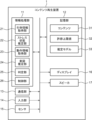
- FIG. 1 is a diagram showing the configuration of a content playback device 1 according to an embodiment of the present disclosure.
- the content playback device 1 may be VR goggles, AR glasses, a head-mounted display, or the like, but is not limited to these examples and may be anything that can provide visual and/or auditory content to a user.
- the content playback device 1 includes an information processing unit 11, a memory unit 12, a communication unit 13, an input unit 14, a sensor 15, a display 16, and a speaker 17.
- the information processing unit 11 is configured using a processor (information processing device) such as a CPU or GPU.
- the storage unit 12 is configured using a semiconductor memory or the like.
- the communication unit 13 is configured using a communication module compatible with any communication standard such as Bluetooth (registered trademark) or Wi-Fi.
- the input unit 14 is configured using a touch panel or a voice input device or the like.
- the sensor 15 is configured using a heart rate sensor, a skin potential sensor, a temperature sensor, a camera, a myoelectric potential sensor, a position sensor, a motion capture sensor, a gaze sensor, or the like mounted on a VR goggle or the like or capable of communicating with a VR goggle or the like.
- the display 16 is configured using a liquid crystal display or an organic EL display or the like.
- the information processing unit 11 may be implemented in an external terminal or a server device capable of communicating with the content reproduction device 1.
- the storage unit 12 may be implemented in an external terminal or a server device capable of communicating with the content reproduction device 1.
- the external terminal includes a personal computer, a smartphone, a tablet terminal, or the like.
- the server device includes an edge server or a cloud server, or the like.
- both the information processing unit 11 and the storage unit 12 may be implemented in a cloud server.
- the storage unit 12 stores content 31, an allowable upper limit value 32, and an estimation model 33.
- the content 31 is VR content, AR content, or the like to be played by the content playback device 1.
- the content 31 includes at least one of video and music.
- the video is output from the display 16, and the music is output from the speaker 17, thereby allowing the user to experience the content 31.
- the allowable upper limit value 32 is a value indicating the allowable limit of the stress state for each user, and can be set arbitrarily by the user by inputting data into the input unit 14.
- the estimation model 33 is, for example, a trained machine learning model.
- the estimation model 33 includes a stress state estimation model and an intention estimation model.
- the stress state estimation model is a model for estimating a user's stress state (stress value or stress level) based on the measured values of the user's biological information.
- the biological information is physiological indices that can be measured by various sensors 15 mounted on the content playback device 1, and includes at least one of heart rate, sweat rate, skin potential, brain waves, surface temperature, facial expression, gaze, voice, and myoelectric potential.
- the stress state estimation model is an estimation model that uses the measured values by the sensors 15 targeting the user as explanatory variables and the user's stress state as a target variable.
- the stress state estimation model is generated by machine learning using the measured values by the sensors 15 when the user experiences the content 31 and the correct answer label indicating the user's stress state at that time as training data.
- the stress state estimation model is not limited to a machine learning model, and may be a linear or nonlinear function formula that specifies the relationship between one or more physiological indices and the stress state.
- the intention estimation model is a model for estimating a user's intention with respect to a user interface based on motion information indicating the user's actions with respect to the user interface.
- the motion information includes motion instruction information that can be measured or input by a motion capture sensor, a gaze sensor, a voice input device, or the like.
- the motion capture sensor includes optical, inertial, or image sensors.
- the intention estimation model is an estimation model that uses motion information with respect to a user interface as an explanatory variable and the user's intention as a target variable.
- the intention estimation model is generated by machine learning using, as teacher data, measurement values obtained by a motion capture sensor or the like when the user experiences the content 31 and correct answer labels indicating the user's intention at that time. Note that the intention estimation model is not limited to a machine learning model, and may be a linear or nonlinear function formula that specifies the relationship between the motion information and the user's intention.
- the information processing unit 11 includes a bioinformation acquisition unit 21, a stress state estimation unit 22, a motion information acquisition unit 23, an intention estimation unit 24, a judgment unit 25, and a control unit 26, as functions realized by the processor executing a program read from a non-volatile recording medium such as a computer-readable ROM.
- the above programs are programs for causing the information processing unit 11, which serves as an information processing device mounted on the content playback device 1, to function as the bioinformation acquisition unit 21 (biometric information acquisition means), the stress state estimation unit 22 (stress state estimation means), the motion information acquisition unit 23 (motion information acquisition means), the intention estimation unit 24 (intention estimation means), the judgment unit 25 (judgment means), and the control unit 26 (control means). Details of the processing contents executed by each processing unit will be described later.
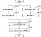
- FIG. 2 is a flowchart showing the flow of processing executed by the information processing unit 11.
- the biometric information acquisition unit 21 acquires biometric information of the user by acquiring measurements from the sensor 15 that targets the user.
- step SP02 the stress state estimation unit 22 inputs the biometric information acquired in step SP01 as an input value into a stress state estimation model, and estimates the user's stress state as an output value from the stress state estimation model at that time.
- step SP03 the motion information acquisition unit 23 acquires motion information of the user relative to the user interface, for example by acquiring measurements by the motion capture sensor from the motion capture sensor.
- step SP04 the intention estimation unit 24 inputs the action information acquired in step SP03 as an input value into the intention estimation model, and estimates the user's intention with respect to the user interface as the output value from the intention estimation model at that time.
- the determination unit 25 determines the user's stress factor based on the stress state estimation result in step SP02 and the intention estimation result in step SP04. Specifically, if the stress state estimation result in step SP02 exceeds the allowable upper limit value 32, the determination unit 25 determines that the user is experiencing mental stress that exceeds the allowable level, and that the stress factor is caused by a mismatch between the user's intention and the user interface. In other words, the determination unit 25 determines that the stress factor is caused by the user interface.
- step SP06 if the control unit 26 determines in step SP05 that the stress factor is caused by the user interface, it controls the user interface to relieve the user's stress state.
- step SP01 the acquisition of biometric information (step SP01) and estimation of stress state (step SP02) are processed in parallel with the acquisition of motion information (step SP03) and estimation of intention (step SP04).
- steps SP01 and SP02 and steps SP03 and SP04 may be processed sequentially, or the order may be reversed.
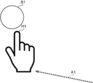
- FIGS. 3A and 3B are diagrams showing a first example of control of a user interface.
- the user interface is a screen of a virtual space displayed on the display 16 of the VR goggles.
- the user's intention with respect to the user interface is to select an object in the virtual space.
- a ball figure B1 which corresponds to the object
- a right hand figure H1 which corresponds to the user, are displayed in the virtual space.
- control unit 26 performs an effect in which the right hand figure H1 is translated from its current display position toward figure B1, as indicated by the arrow A1.
- control unit 26 performs an effect in which the virtual character C1 carries the ball figure B1 from its original position to the display position of the figure H1 on the right hand, as indicated by the arrow A2.
- the determination unit 25 determines that the object selection method using the performance shown in FIG. 3A is inconsistent for the user, and that the object selection method using the performance shown in FIG. 3B is consistent for the user. In this case, the control unit 26 applies the object selection method using the performance shown in FIG. 3B to the user from the next time onwards.
- the determination unit 25 determines that the object selection method using the performance shown in FIG. 3B is inconsistent for the user, and that the object selection method using the performance shown in FIG. 3A is consistent for the user. In this case, the control unit 26 applies the object selection method using the performance shown in FIG. 3A to the user from the next time onwards.
- the object selection method is not limited to the above two examples, and may be three or more.
- the relationship between the selection method and stress level is learned in advance for each user, a prediction model or table information defining that relationship is stored in the memory unit 12, and the control unit 26 applies the optimal selection method for each user by referring to the prediction model or table information.
- the optimal selection method is preferably the method among the multiple selection methods that minimizes the user's stress state, and may be the method that brings the user's stress state below the allowable upper limit value 32.
- the first example in controlling a user interface for selecting an object in a virtual space, by selecting from among a number of methods a method that reduces the user's stress state to a minimum or below the upper tolerable value of 32, it is possible to effectively alleviate the user's stress state.
- FIG. 4 is a diagram showing a second example of user interface control.
- the user interface is a virtual space screen displayed on the display 16 of the VR goggles.
- the user's intention with respect to the user interface is to select an object in the virtual space.
- a ball figure B1 which corresponds to the object, is displayed in the background in the virtual space
- a right hand figure H1 which corresponds to the user, is displayed in the foreground.
- control unit 26 performs an effect in which the ball figure B1 moves, for example by flying, from its original position toward the figure H1 on the right hand, as indicated by the arrow A3.
- the determination unit 25 determines that the object selection method using the high-speed flight performance is inconsistent for the user, and that the object selection method using the low-speed flight performance is consistent for the user. In this case, the control unit 26 applies the object selection method using the low-speed flight performance to the user from the next time onwards.
- the determination unit 25 determines that the object selection method using the low-speed flight performance is inconsistent for the user, and that the object selection method using the high-speed flight performance is consistent for the user. In this case, the control unit 26 applies the object selection method using the high-speed flight performance to the user from the next time onwards.
- the flying speed of the object is not limited to the above two patterns, and may be three or more patterns.
- the relationship between flying speed and stress level is learned in advance for each user, a prediction model or table information defining that relationship is stored in the memory unit 12, and the control unit 26 applies the optimal flying speed for each user by referring to the prediction model or table information.
- the optimal flying speed is preferably the speed among multiple flying speeds that minimizes the user's stress state, and may be the speed at which the user's stress state is below the allowable upper limit value 32.
- the flying speed of the object is set so that the user's stress state is at or below the minimum or upper allowable limit value of 32, thereby making it possible to effectively alleviate the user's stress state.
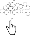
- FIGS. 5A and 5B are schematic diagrams showing a third example of control of a user interface.
- the user interface is a screen of a virtual space displayed on the display 16 of the VR goggles.
- the user's intention with respect to the user interface is to select a specific object from among a plurality of objects in the virtual space.
- a number of ball figures B corresponding to a number of objects, and a right hand figure H1 corresponding to the user are displayed in the virtual space.
- control unit 26 performs an effect in which, when figure H1 approaches figure B to a certain extent, figure B5, whose horizontal coordinate is closest to figure H1, is selected.
- the control unit 26 selects three figures B4 to B6 in the state of FIG. 5A in order of their horizontal coordinates being closest to figure H1, and then enlarges and moves figures B4 to B6 forward from their original positions as indicated by arrows A4 to A6, and selects one of figures B4 to B6 after the enlarged movement by bringing figure H1 into contact with figure B5, one of figures B4 to B6.
- the control unit 26 may further perform an effect of moving figures B4 to B6 to the virtual character C1 shown in FIG. 3B.
- the determination unit 25 determines that the object selection method using the performance shown in FIG. 5A is inconsistent for the user, and that the object selection method using the performance shown in FIG. 5B is consistent for the user. In this case, the control unit 26 applies the object selection method using the performance shown in FIG. 5B to the user from the next time onwards.
- the determination unit 25 determines that the object selection method using the performance shown in FIG. 5B is inconsistent for the user, and that the object selection method using the performance shown in FIG. 5A is consistent for the user. In this case, the control unit 26 applies the object selection method using the performance shown in FIG. 5A to the user from the next time onwards.
- the object selection method is not limited to the above two examples, and may be three or more.
- the relationship between the selection method and stress level is learned in advance for each user, a prediction model or table information defining that relationship is stored in the memory unit 12, and the control unit 26 applies the optimal selection method for each user by referring to the prediction model or table information.
- the optimal selection method is preferably the method among the multiple selection methods that minimizes the user's stress state, and may be the method that brings the user's stress state below the allowable upper limit value 32.
- a method that reduces the user's stress state to a minimum or below the upper tolerable value of 32 is selected from among a plurality of methods, thereby making it possible to effectively alleviate the user's stress state.
- FIGS. 6A and 6B are schematic diagrams showing a fourth example of control of a user interface.
- the user interface is a screen of a virtual space (augmented reality space) that corresponds to the user's field of view F and is displayed on the display 16 of the AR glasses.
- the user's intention with respect to the user interface is to select an object within the virtual space.
- the right half of a ball figure B1 which corresponds to the object, is displayed on the left edge of the user's field of view F.
- the intention estimation unit 24 estimates the user's intention to select figure B1 displayed on the left edge of the field of view F. Furthermore, the determination unit 25 determines that the fact that the selection target figure B1 is located on the edge of the field of view F and is therefore difficult to select is a stress factor for the user.
- control unit 26 controls the user interface to move and display the selected figure B1 from the left edge of the field of view F toward the center, as shown by the arrow A7 in FIG. 6B.
- the control unit 26 may further perform an effect in which the figure B1 is moved to the virtual character C1 shown in FIG. 3B.
- an object located at the edge of the user's field of view F is moved toward the center of the field of view F and displayed, thereby effectively reducing the user's stress.
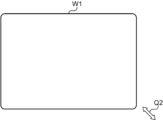
- FIGS. 7A and 7B are diagrams showing a fifth example of control of a user interface.
- the user interface is the display screen of the display 16.
- the user's intention with respect to the user interface is to enlarge or reduce window W1 displayed on the screen by moving the mouse cursor to the bottom right edge of the window W1 and dragging it.
- the intention estimation unit 24 estimates the user's intention to select the bottom right edge of the window W1. Furthermore, the determination unit 25 determines that the inability to successfully select the bottom right edge of the window W1 with the mouse cursor Q1 is the user's stress factor.
- control unit 26 controls the user interface to accept a drag operation even when the mouse cursor Q2 is located not only directly above the bottom right edge of the window W1 but also in the vicinity thereof.
- the single-arrow mouse cursor Q1 By switching from the single-arrow mouse cursor Q1 to the double-arrow mouse cursor Q2, it becomes possible to select the position for the drag operation.
- motion information indicating a user's motion with respect to a user interface is acquired, and the user's intention with respect to the user interface is estimated based on the motion information. Therefore, the user interface can be controlled to match the estimated user's intention, and as a result, the user's stress state can be alleviated.
- control unit 26 controls the user interface to relieve the user's stress state, thereby making it possible to effectively relieve the user's stress state.
- the intention estimation unit 24 may estimate the user's intention with respect to the user interface based on the motion information acquired by the motion information acquisition unit 23 and the biometric information acquired by the biometric information acquisition unit 21. For example, a facial expression image of the user captured by a camera, which is one of the sensors 15, may be used to estimate the user's intention.
- the intention estimation unit 24 may estimate the user's intention with respect to the user interface based on the motion information acquired by the motion information acquisition unit 23 and situation information of the user interface indicating the progress of the content 31, etc. For example, the user's intention may be estimated using the situation of the current scene of the content 31 and the motion information of the user according to that situation.
- the stress state estimation unit 22 may estimate the user's stress state based on the biometric information acquired by the biometric information acquisition unit 21 and the motion information and/or situation information of the user interface acquired by the motion information acquisition unit 23.
- This disclosure is particularly useful when applied to services such as VR, AR, or the metaverse that uses them.
Landscapes
- Engineering & Computer Science (AREA)
- General Engineering & Computer Science (AREA)
- Theoretical Computer Science (AREA)
- Physics & Mathematics (AREA)
- General Physics & Mathematics (AREA)
- Human Computer Interaction (AREA)
- Computer Graphics (AREA)
- Computer Hardware Design (AREA)
- Software Systems (AREA)
- User Interface Of Digital Computer (AREA)
Priority Applications (1)
| Application Number | Priority Date | Filing Date | Title |
|---|---|---|---|
| JP2025502119A JPWO2024176568A1 (https=) | 2023-02-22 | 2023-12-05 |
Applications Claiming Priority (2)
| Application Number | Priority Date | Filing Date | Title |
|---|---|---|---|
| JP2023-026279 | 2023-02-22 | ||
| JP2023026279 | 2023-02-22 |
Publications (1)
| Publication Number | Publication Date |
|---|---|
| WO2024176568A1 true WO2024176568A1 (ja) | 2024-08-29 |
Family
ID=92500792
Family Applications (1)
| Application Number | Title | Priority Date | Filing Date |
|---|---|---|---|
| PCT/JP2023/043540 Ceased WO2024176568A1 (ja) | 2023-02-22 | 2023-12-05 | 情報処理方法、情報処理装置、及びプログラム |
Country Status (2)
| Country | Link |
|---|---|
| JP (1) | JPWO2024176568A1 (https=) |
| WO (1) | WO2024176568A1 (https=) |
Citations (4)
| Publication number | Priority date | Publication date | Assignee | Title |
|---|---|---|---|---|
| JPH10143309A (ja) * | 1996-11-06 | 1998-05-29 | Nec Yonezawa Ltd | キーボードレス・コンピュータ |
| JP2001184139A (ja) * | 1999-12-27 | 2001-07-06 | Nec Corp | ユーザインタフェースシステム |
| JP2019079342A (ja) * | 2017-10-25 | 2019-05-23 | 富士通株式会社 | 状態判定方法、状態判定プログラム及び状態判定装置 |
| JP2022510793A (ja) * | 2018-12-14 | 2022-01-28 | バルブ コーポレーション | ビデオゲーム状態を動的に制御するためのプレイヤーバイオフィードバック |
-
2023
- 2023-12-05 WO PCT/JP2023/043540 patent/WO2024176568A1/ja not_active Ceased
- 2023-12-05 JP JP2025502119A patent/JPWO2024176568A1/ja active Pending
Patent Citations (4)
| Publication number | Priority date | Publication date | Assignee | Title |
|---|---|---|---|---|
| JPH10143309A (ja) * | 1996-11-06 | 1998-05-29 | Nec Yonezawa Ltd | キーボードレス・コンピュータ |
| JP2001184139A (ja) * | 1999-12-27 | 2001-07-06 | Nec Corp | ユーザインタフェースシステム |
| JP2019079342A (ja) * | 2017-10-25 | 2019-05-23 | 富士通株式会社 | 状態判定方法、状態判定プログラム及び状態判定装置 |
| JP2022510793A (ja) * | 2018-12-14 | 2022-01-28 | バルブ コーポレーション | ビデオゲーム状態を動的に制御するためのプレイヤーバイオフィードバック |
Also Published As
| Publication number | Publication date |
|---|---|
| JPWO2024176568A1 (https=) | 2024-08-29 |
Similar Documents
| Publication | Publication Date | Title |
|---|---|---|
| US12566532B2 (en) | Methods for interacting with virtual controls and/or an affordance for moving virtual objects in virtual environments | |
| US12265657B2 (en) | Methods for navigating user interfaces | |
| CN111580652B (zh) | 视频播放的控制方法、装置、增强现实设备及存储介质 | |
| US12106353B2 (en) | System and method for generating a product recommendation in a virtual try-on session | |
| KR20220137770A (ko) | 시선 기반 내비게이션을 위한 디바이스들, 방법들, 및 그래픽 사용자 인터페이스들 | |
| CN113646732A (zh) | 基于神经肌肉数据获得控制方案的系统和方法 | |
| US10831266B2 (en) | Personalized adaptation of virtual reality content based on eye strain context | |
| JP7713517B2 (ja) | 眼運動に基づくエクステンデッドリアリティ環境相互作用の方法およびシステム | |
| JP2024508691A (ja) | 三次元環境におけるアバターの提示のためのインタフェース | |
| US12594496B2 (en) | Translation of sign language in a virtual environment | |
| US12145060B2 (en) | Methods and systems to activate selective navigation or magnification of screen content | |
| KR20200091988A (ko) | 장치를 제어하기 위한 방법 및 그 전자 장치 | |
| US12569752B2 (en) | Gesture translation with modification based on game context | |
| Bhaskaran et al. | Immersive user experiences: trends and challenges of using XR technologies | |
| KR20200081529A (ko) | 사회적 수용성을 고려한 hmd 기반 사용자 인터페이스 방법 및 장치 | |
| CN117193589A (zh) | 界面交互控制方法、计算机设备和计算机可读存储介质 | |
| CN112613374A (zh) | 人脸可见区域解析与分割方法、人脸上妆方法及移动终端 | |
| WO2024176568A1 (ja) | 情報処理方法、情報処理装置、及びプログラム | |
| WO2023216613A1 (zh) | 一种控制方法、电子设备及计算机存储介质 | |
| EP4629033A1 (en) | Improving extended-reality rendering using automatic panel enhancements based on hardware-pixels-per-degree estimations, and systems and methods of use thereof | |
| US20250278902A1 (en) | Techniques for coordinating artificial-reality interactions using augmented-reality interaction guides for performing interactions with physical objects within a user's physical surroundings, and systems and methods for using such techniques | |
| US12153854B1 (en) | Animation of hand-finger communicator with real-world voice output | |
| CN120523317A (zh) | 人机交互方法和装置、存储介质、人机交互系统 | |
| CN121334490A (zh) | 一种图像处理方法及装置 | |
| JP2025122375A (ja) | 情報処理装置、情報処理装置の制御方法、およびプログラム |
Legal Events
| Date | Code | Title | Description |
|---|---|---|---|
| 121 | Ep: the epo has been informed by wipo that ep was designated in this application |
Ref document number: 23924212 Country of ref document: EP Kind code of ref document: A1 |
|
| WWE | Wipo information: entry into national phase |
Ref document number: 2025502119 Country of ref document: JP |
|
| NENP | Non-entry into the national phase |
Ref country code: DE |
|
| 122 | Ep: pct application non-entry in european phase |
Ref document number: 23924212 Country of ref document: EP Kind code of ref document: A1 |