WO2024176390A1 - データ分割装置、及びコンピュータ読み取り可能な記録媒体 - Google Patents
データ分割装置、及びコンピュータ読み取り可能な記録媒体 Download PDFInfo
- Publication number
- WO2024176390A1 WO2024176390A1 PCT/JP2023/006479 JP2023006479W WO2024176390A1 WO 2024176390 A1 WO2024176390 A1 WO 2024176390A1 JP 2023006479 W JP2023006479 W JP 2023006479W WO 2024176390 A1 WO2024176390 A1 WO 2024176390A1
- Authority
- WO
- WIPO (PCT)
- Prior art keywords
- data
- unit
- section
- predetermined
- divided
- Prior art date
- Legal status (The legal status is an assumption and is not a legal conclusion. Google has not performed a legal analysis and makes no representation as to the accuracy of the status listed.)
- Ceased
Links
Images


Classifications
-
- B—PERFORMING OPERATIONS; TRANSPORTING
- B23—MACHINE TOOLS; METAL-WORKING NOT OTHERWISE PROVIDED FOR
- B23Q—DETAILS, COMPONENTS, OR ACCESSORIES FOR MACHINE TOOLS, e.g. ARRANGEMENTS FOR COPYING OR CONTROLLING; MACHINE TOOLS IN GENERAL CHARACTERISED BY THE CONSTRUCTION OF PARTICULAR DETAILS OR COMPONENTS; COMBINATIONS OR ASSOCIATIONS OF METAL-WORKING MACHINES, NOT DIRECTED TO A PARTICULAR RESULT
- B23Q17/00—Arrangements for observing, indicating or measuring on machine tools
- B23Q17/09—Arrangements for observing, indicating or measuring on machine tools for indicating or measuring cutting pressure or for determining cutting-tool condition, e.g. cutting ability, load on tool
-
- G—PHYSICS
- G05—CONTROLLING; REGULATING
- G05B—CONTROL OR REGULATING SYSTEMS IN GENERAL; FUNCTIONAL ELEMENTS OF SUCH SYSTEMS; MONITORING OR TESTING ARRANGEMENTS FOR SUCH SYSTEMS OR ELEMENTS
- G05B19/00—Program-control systems
- G05B19/02—Program-control systems electric
- G05B19/18—Numerical control [NC], i.e. automatically operating machines, in particular machine tools, e.g. in a manufacturing environment, so as to execute positioning, movement or co-ordinated operations by means of program data in numerical form
- G05B19/406—Numerical control [NC], i.e. automatically operating machines, in particular machine tools, e.g. in a manufacturing environment, so as to execute positioning, movement or co-ordinated operations by means of program data in numerical form characterised by monitoring or safety
- G05B19/4063—Monitoring general control system
-
- G—PHYSICS
- G05—CONTROLLING; REGULATING
- G05B—CONTROL OR REGULATING SYSTEMS IN GENERAL; FUNCTIONAL ELEMENTS OF SUCH SYSTEMS; MONITORING OR TESTING ARRANGEMENTS FOR SUCH SYSTEMS OR ELEMENTS
- G05B19/00—Program-control systems
- G05B19/02—Program-control systems electric
- G05B19/18—Numerical control [NC], i.e. automatically operating machines, in particular machine tools, e.g. in a manufacturing environment, so as to execute positioning, movement or co-ordinated operations by means of program data in numerical form
- G05B19/406—Numerical control [NC], i.e. automatically operating machines, in particular machine tools, e.g. in a manufacturing environment, so as to execute positioning, movement or co-ordinated operations by means of program data in numerical form characterised by monitoring or safety
- G05B19/4065—Monitoring tool breakage, life or condition
-
- G—PHYSICS
- G05—CONTROLLING; REGULATING
- G05B—CONTROL OR REGULATING SYSTEMS IN GENERAL; FUNCTIONAL ELEMENTS OF SUCH SYSTEMS; MONITORING OR TESTING ARRANGEMENTS FOR SUCH SYSTEMS OR ELEMENTS
- G05B23/00—Testing or monitoring of control systems or parts thereof
- G05B23/02—Electric testing or monitoring
Definitions
- the present disclosure relates to a data division device and a computer-readable recording medium.
- the data division device disclosed herein solves the above problem by matching the features of data acquired from industrial machinery and dividing data related to the operation of the industrial machinery by context.
- An aspect of the present disclosure is a data division device including: a data acquisition unit that acquires data related to the operation of an industrial machine; a section division unit that divides a section in the time direction of the data acquired by the data acquisition unit into predetermined sections based on a predetermined context value for determining a context related to the operation of the industrial machine; a feature calculation unit that calculates a predetermined feature value indicating a characteristic of each section for each section divided by the section division unit; a reference data storage unit that stores reference data that associates a section label with a predetermined feature value indicating a characteristic of each section for a plurality of sections divided in the time direction; a matching unit that performs a matching process between the reference data and the predetermined feature value for each section calculated by the feature calculation unit and assigns the section label to the section divided by the section division unit; and an output unit that outputs information related to the divided sections.
- FIG. 2 is a hardware configuration diagram of the data division device according to the first embodiment.
- 1 is a block diagram showing functions of a data division device according to a first embodiment; 4 is a graph showing an example of a transition of a command position commanded to a motor in one machining cycle.
- 11 is a table illustrating an example of feature amounts for each section calculated by a feature amount calculation unit.
- FIG. 11 is a table illustrating an example of reference data.
- FIG. 13 is a schematic diagram illustrating an example of an output result of data division.
- FIG. 11 is a block diagram showing the functions of a data division device according to a second embodiment.
- FIG. 11 is a functional block diagram of a data division device according to another embodiment.
- FIG. 1 is a schematic hardware configuration diagram showing a main part of a data division device according to a first embodiment of the present disclosure.
- the data division device 1 of the present disclosure can be implemented, for example, as a control device for controlling an industrial machine.
- the data division device 1 of the present disclosure can be implemented on a computer such as a personal computer attached to a control device for controlling an industrial machine, a personal computer connected to the control device via a wired/wireless network, a cell computer, a fog computer 6, or a cloud server 7.
- a personal computer equipped with a diagnostic function and connected to a control device for controlling an industrial machine via a network.
- the CPU 11 provided in the data division device 1 is a processor that controls the entire data division device 1.
- the CPU 11 reads the system program stored in the ROM 12 via the bus 22, and controls the entire data division device 1 according to the system program.
- the RAM 13 temporarily stores temporary calculation data, display data, and various data input from outside.
- the non-volatile memory 14 is composed of, for example, a memory backed up by a battery (not shown) or an SSD (Solid State Drive), and the memory state is maintained even when the power supply of the data division device 1 is turned off.
- the non-volatile memory 14 stores programs and data read from the external device 72 via the interface 15, programs and data input via the input device 71, programs and data acquired from the industrial machine 3, and the like.
- the data includes control data such as a command position, a command speed, a position feedback value, and a speed feedback value, sensor data such as the motor current, voltage, temperature, vibration, and sound detected by the sensor 4 attached to the industrial machine 3, the program number of the control program, and the tool number of the tool being used.
- the data stored in the non-volatile memory 14 may be expanded in the RAM 13 when executed/used.
- various system programs such as a publicly known analysis program are written in advance in the ROM 12.
- the interface 15 is an interface for connecting the CPU 11 of the data division device 1 to an external device 72 such as a USB device.
- an external device 72 such as a USB device.
- pre-stored control programs and data related to the operation of each industrial machine 3 can be read from the external device 72.
- control programs and setting data edited within the data division device 1 can be stored in an external storage means via the external device 72.
- the interface 20 is an interface for connecting the CPU 11 of the data splitting device 1 to a wired or wireless network 5.
- the network 5 is connected to the industrial machines 3, fog computers 6, cloud servers 7, etc., and exchanges data with the data splitting device 1.
- the display device 70 displays various data loaded into memory, data obtained as a result of executing programs, etc., output via the interface 17.
- the input device 71 which is comprised of a keyboard, pointing device, etc., passes instructions and data based on operations by the operator to the CPU 11 via the interface 18.
- the industrial machinery 3 is a machine such as a machine tool, an injection molding machine, or a robot.
- the industrial machinery 3 is equipped with sensors 4 that detect predetermined physical quantities related to the operation of at least each part of the industrial machinery 3.
- the data division device 1 acquires data such as predetermined command values and signal values, predetermined physical quantities detected by the sensors 4, the program number of the control program being executed, and the tool number of the tool being used from the industrial machinery 3 via the network 5 and the interface 20.
- the acquired predetermined data is stored in the RAM 13 through the non-volatile memory 14 and processed by the CPU 11.
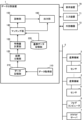
- FIG. 2 is a schematic block diagram showing the functions of the data splitting device 1 according to the first embodiment of the present disclosure.
- Each function of the data splitting device 1 according to this embodiment is realized by the CPU 11 of the data splitting device 1 shown in FIG. 1 executing a system program and controlling the operation of each part of the data splitting device 1.
- the data splitting device 1 of this embodiment includes a data acquisition unit 110, a section splitting unit 120, a feature calculation unit 130, a matching unit 140, a diagnosis unit 150, and an output unit 160.
- a data storage unit 210 which is an area for storing data acquired from the industrial machine 3
- a reference data storage unit 220 which is an area for storing reference data that serves as a criterion for determining the context of the acquired data, are prepared in advance.
- the data acquisition unit 110 acquires predetermined data from the industrial machinery 3, such as predetermined command values and signal values, predetermined physical quantities detected by the sensors 4, program numbers of control programs being executed, and tool numbers of tools being used.
- the data acquired by the data acquisition unit 110 is time-series data obtained by detecting temporal changes in predetermined physical quantities at predetermined intervals.
- the data acquisition unit 110 may acquire data from the industrial machinery 3 via the network 5.
- the data acquisition unit 110 may also acquire data acquired and stored by external devices 72, fog computers 6, cloud servers 7, etc.
- the data acquisition unit 110 stores the acquired data in the data storage unit 210 in association with time.
- the section division unit 120 divides the time-direction section of the data acquired by the data acquisition unit 110 and stored in the data storage unit 210 into predetermined sections.
- the section division unit 120 divides the sections based on a predetermined context value.
- the context value is a data value used to determine the context related to the operation of the industrial machine 3. For example, a command value (command position, command speed, position feedback value, speed feedback value, etc.) issued to the motor that drives the drive unit of the industrial machine 3, a value of a predetermined state signal of the industrial machine 3 (value of a signal during operation, value of a signal during cutting, etc.), a differential value of these values, a predetermined statistical value, etc. can be used as a context value.
- the program number of the control program used to control the industrial machine 3 and the tool number of a tool in use can also be used as a context value.
- a set (vector) of these values may also be used as a context value.
- the section division unit 120 determines that a section in which the predetermined context value is approximately constant is a section corresponding to the same context. Then, the time-direction section of the data is divided into different sections for each of the same contexts. The section division unit 120 outputs information related to the divided sections to the feature calculation unit 130.
- Fig. 3 is a graph showing an example of the transition of the command position commanded to the motor in one machining cycle.
- the interval dividing unit 120 judges that the intervals in which the slope of the command position is constant are the same context, and divides the intervals in the time direction for each context. Then, as shown in Fig. 3, the time direction interval of the data acquired in one machining cycle is divided into 14 intervals from a1 to a14 .
- the feature amount calculation unit 130 calculates a predetermined feature amount for each section divided by the section division unit 120.
- the predetermined feature amount is a representative value indicating the feature amount in the section.
- the predetermined feature amount may be a command value (command position, command speed, position feedback value, speed feedback value, etc.) commanded to the motor driving the drive unit of the industrial machine 3 in each section, a value of a predetermined state signal of the industrial machine 3 (value of a signal during operation, value of a signal during cutting, etc.), a differential value of these values, a predetermined statistical value, etc.
- the predetermined feature amount may be a program number of a control program used to control the industrial machine 3, a tool number of a tool in use, a section length of the section, etc.
- FIG. 4 is a table diagram illustrating an example of the feature amount for each section calculated by the feature amount calculation unit 130.
- a set of three values is calculated as the feature amount for each section illustrated in FIG. 3.
- the feature amount for section a3 is a set of three values x 1_3 , x 2_3 , and x 3_3 .
- the feature amount calculation unit 130 outputs the feature amount calculated for each section to the matching unit 140 .
- the matching unit 140 determines the correspondence between each section in the diagnosis target data and each section in the reference data stored in the reference data storage unit 220, based on the feature for each section calculated by the feature calculation unit 130.
- the reference data is data in which section labels are associated with values or sets of values (vectors) of predetermined feature values in each section for multiple sections divided in the time direction and arranged in chronological order.
- the reference data is created in advance based on data related to the operation of the industrial machine 3 obtained by experimentally operating the industrial machine 3 according to the control program. It is preferable to use the same type of context value as the context value used by the section division unit 120 to divide the sections for dividing the reference data. It is also preferable that the predetermined feature for each section in the reference data is the same type as the feature calculated by the feature calculation unit 130.
- FIG. 5 shows an example of the reference data.
- the feature quantities in each of the n sections from section S 1 to section S n are associated with each other.
- the matching unit 140 matches the correspondence between the feature quantities for each section calculated by the feature quantity calculation unit 130 as shown in FIG. 4 and the feature quantities for each section of the reference data as shown in FIG. 5.
- a known elastic matching method such as DP matching or hidden Markov model may be used.
- the matching unit 140 assigns the label of the section in the reference data to each section divided by the section division unit 120.
- the matching unit 140 outputs information related to the labeled sections to the diagnosis unit 150 and the output unit 160.
- the diagnostic unit 150 performs a predetermined diagnostic process for each section. Then, it outputs the diagnostic results to the output unit 160.
- the predetermined diagnostic process may be, for example, a diagnostic process for determining whether the operation of the industrial machine 3 is normal/abnormal. It may also be a diagnostic process related to tool wear/breakage, or a diagnostic process for the machining quality of the workpiece.
- the diagnostic process by the diagnostic unit 150 may be a simple diagnostic process in which a specific data value in each section is compared with a predetermined threshold value. Alternatively, a specific statistical amount may be calculated based on one or more data values in the section, and a diagnosis may be made based on the calculated statistical amount. Furthermore, the diagnostic process may use known machine learning techniques. The diagnostic unit 150 may use different types of diagnostic process and different values such as threshold values used for diagnosis depending on each section to be diagnosed. Diagnostic process may not be performed on data in sections that do not require diagnosis.
- the output unit 160 outputs the data divided by the interval division unit 120 and divided into intervals to which the matching unit 140 has assigned labels. For example, as illustrated in FIG. 6, the output unit 160 may display and output the results of dividing the data acquired by the data acquisition unit 110 into intervals on a screen. The data divided into intervals may also be output to a recording area provided in advance on the non-volatile memory 14 or the like. Furthermore, the data may be sent and output to a higher-level computer such as the industrial machine 3, fog computer 6, or cloud server 7.
- a higher-level computer such as the industrial machine 3, fog computer 6, or cloud server 7.
- the output unit 160 may be configured to output data related to the results of the diagnostic processing by the diagnosis unit 150.
- the output unit 160 may be configured to output the results of the diagnostic processing performed by the diagnosis unit 150 for each section to the display device 70, a recording area provided in advance on the non-volatile memory 14, or a higher-level computer such as the industrial machine 3, the fog computer 6, or the cloud server 7.
- the data division device 1 having the above configuration can divide the acquired data into sections by matching it with reference data based on the acquired data even in situations where detailed context related to the operation of the industrial machine 3 cannot be obtained. This makes it possible to perform diagnosis for each context. If a valid diagnostic process is assigned to the context in advance, diagnosis can be performed automatically without the user having to specify the range of data to be diagnosed.
- a predetermined amount related to tool life can be diagnosed based on the tool number of the tool being used, the characteristic information of the tool corresponding to that tool number, and values related to motor control (torque command, etc.).
- each coefficient of the relational equation that calculates the predetermined amount related to tool life can be determined in advance based on the cutting conditions (cutting speed, cutting depth, number of tool teeth, etc.) and the measured torque command value when the amount of wear is known. It is also possible to predict future wear based on the general relational equation between cutting time and wear amount, and the wear amount estimated above, and diagnose the tool life based on the future amount of wear.
- quantities related to the quality of the workpiece can also be diagnosed from values related to motor control (such as torque commands).
- a certain amount of data pairs of torque commands and quantities related to the quality of a specified machining section are collected in advance and prepared together with reference data. Using this prepared data, a supervised learning model can be generated that diagnoses quantities related to the quality of the machining section from features calculated based on the torque commands.
- the industrial machinery 3 to be diagnosed it is not limited to machine tools, but can also be a variety of machines such as welding robots (where the plate thickness differs depending on the welding point, the diagnosis is made by dividing it into contexts rather than a uniform diagnosis), deburring robots (where the cutting allowance for each deburring point is divided into contexts and the diagnosis is made), and screw tightening robots (where the required torque differs depending on the diameter and length of the screw, the diagnosis is made by dividing the contexts).
- welding robots where the plate thickness differs depending on the welding point, the diagnosis is made by dividing it into contexts rather than a uniform diagnosis
- deburring robots where the cutting allowance for each deburring point is divided into contexts and the diagnosis is made
- screw tightening robots where the required torque differs depending on the diameter and length of the screw, the diagnosis is made by dividing the contexts.
- the data values are not used directly for matching; instead, the feature values that represent the interval are calculated, and then matching between the feature values is performed to find the correspondence with the interval of the reference data. This makes it possible to reduce calculation costs compared to, for example, matching processing that uses time series data itself.
- the following describes a data division device according to the second embodiment.
- the data division device 1 according to the present embodiment has the same hardware configuration as the data division device 1 according to the first embodiment.
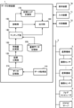
- FIG. 7 is a schematic block diagram showing the functions of the data splitting device 1 according to the second embodiment of the present disclosure.
- Each function of the data splitting device 1 according to this embodiment is realized by the CPU 11 of the data splitting device 1 shown in FIG. 1 executing a system program and controlling the operation of each part of the data splitting device 1.
- the data splitting device 1 of this embodiment includes a data acquisition unit 110, a section splitting unit 120, a feature calculation unit 130, a matching unit 140, a diagnosis unit 150, and an output unit 160, as well as a section score calculation unit 170.
- the RAM 13 to the non-volatile memory 14 of the data splitting device 1 are provided in advance with a data storage unit 210, which is an area for storing data acquired from the industrial machine 3, and a reference data storage unit 220, which is an area for storing reference data that serves as a criterion for determining the context of the acquired data.
- the data acquisition unit 110, section division unit 120, feature calculation unit 130, matching unit 140, and diagnosis unit 150 of this embodiment have the same functions as the data acquisition unit 110, section division unit 120, feature calculation unit 130, matching unit 140, and diagnosis unit 150 of the first embodiment, respectively.
- the section score calculation unit 170 calculates a score indicating the statistical variation of the diagnosis results for each section based on the history of the diagnosis results by the diagnosis unit 150.
- the section score calculation unit 170 acquires the diagnosis results output by the diagnosis unit 150, for example, each time one cycle of processing is performed. Then, it calculates the variance value and standard deviation value from the history of the diagnosis results.
- the section score calculation unit 170 may calculate a score indicating the variation in short cycles (e.g., 5 to 10 cycles). It may also calculate a score indicating the trend of change in the diagnosis results in long cycles (50 to 100 cycles). Then, it outputs these calculated scores to the output unit 160.
- the output unit 160 refers to the score indicating the variation calculated by the section score calculation unit 170 when outputting data related to the results of the diagnostic process by the diagnostic unit 150. Then, for a diagnostic result of a section in which the score indicating the variation in a short cycle exceeds a predetermined threshold, the diagnostic result may be determined to be invalid for diagnosis. In addition, if there is a large tendency for the diagnostic result to change in a long cycle, the output unit 160 may determine that the diagnostic result of that section can be suitably used for diagnosis. The output unit 160 may output the result of such a determination together with the diagnostic result. At this time, the diagnostic results may be sorted and displayed on the screen in order of the score for each section. At this time, only a predetermined number of diagnostic results with the highest scores may be displayed.
- the data splitting device 1 which has the above configuration, makes it possible to easily determine which sections of data are valid for diagnosis.
- FIG. 8 is a schematic block diagram showing functions of the data splitting device 1 according to another embodiment of the present disclosure.
- the data splitting device 1 according to the first and second embodiments is described as being equipped with a function as a diagnostic device.
- the diagnostic unit 150 which is a function as a diagnostic device, does not necessarily need to be implemented on the data splitting device 1. It may be implemented on the fog computer 6, the cloud server 7, or another computer.
- a data division device (1) includes a data acquisition unit (110) that acquires data related to the operation of an industrial machine (3); a section division unit (120) that divides a section in a time direction of data acquired by the data acquisition unit (110) into predetermined sections based on a predetermined context value for determining a context related to the operation of the industrial machine (3); a feature calculation unit (130) that calculates a predetermined feature amount indicating a characteristic of each section divided by the section division unit (120); a reference data storage unit (220) that stores reference data in which a section label is associated with a predetermined feature amount indicating a characteristic of each section for a plurality of sections divided in the time direction; a matching unit (140) that performs a matching process between the reference data and the predetermined feature amount for each section calculated by the feature calculation unit (130) and assigns the section label to the section divided by the section division unit (120); and an output unit (
- a data division device (1) according to another aspect of the present disclosure further includes a diagnostic unit (150) that executes a predetermined diagnostic process corresponding to each interval divided by the interval division unit (120).
- a data division device (1) according to another aspect of the present disclosure further includes an interval score calculation unit (170) that calculates a score representing whether an interval is effective for diagnosis from time series data of diagnosis results for each interval by the diagnosis unit (150), and the output unit (160) changes the content to be output based on the value of the score.
- the diagnosing unit (150) diagnoses a quantity related to the tool life of the tool based on the tool number of the tool being used in the section, characteristic information of the tool corresponding to the tool number, and the value of data related to motor control in the section.
- the diagnostic unit (150) calculates a predetermined diagnostic value related to a processing abnormality based on the degree of deviation between the value of data related to motor control acquired under normal conditions and the value of data related to motor control acquired by the data acquisition unit.
- a computer-readable recording medium records a program that causes a computer to function as a data acquisition unit (110) that acquires data related to the operation of an industrial machine (3), a section division unit (120) that divides a section in the time direction of data acquired by the data acquisition unit (110) into predetermined section based on a predetermined context value for determining a context related to the operation of the industrial machine (3), a feature calculation unit (130) that calculates a predetermined feature amount indicating a characteristic of each section divided by the section division unit (120), a matching unit (140) that performs a matching process between reference data in which section labels are associated with predetermined feature amounts indicating characteristics of each section for a plurality of sections divided in the time direction, and the predetermined feature amount for each section
- Reference Signs List 1 Data division device 3 Industrial machine 4 Sensor 5 Network 6 Fog computer 7 Cloud server 11 CPU 12 ROM 13 RAM 14 Non-volatile memory 15 Interface 17, 18, 20 Interface 22 Bus 70 Display device 71 Input device 72 External device 110 Data acquisition unit 120 Section division unit 130 Feature amount calculation unit 140 Matching unit 150 Diagnosis unit 160 Output unit 170 Section score calculation unit 210 Data storage unit 220 Reference data storage unit
Landscapes
- Engineering & Computer Science (AREA)
- Physics & Mathematics (AREA)
- General Physics & Mathematics (AREA)
- Automation & Control Theory (AREA)
- Human Computer Interaction (AREA)
- Manufacturing & Machinery (AREA)
- Mechanical Engineering (AREA)
- Numerical Control (AREA)
Priority Applications (2)
| Application Number | Priority Date | Filing Date | Title |
|---|---|---|---|
| JP2025502013A JPWO2024176390A1 (https=) | 2023-02-22 | 2023-02-22 | |
| PCT/JP2023/006479 WO2024176390A1 (ja) | 2023-02-22 | 2023-02-22 | データ分割装置、及びコンピュータ読み取り可能な記録媒体 |
Applications Claiming Priority (1)
| Application Number | Priority Date | Filing Date | Title |
|---|---|---|---|
| PCT/JP2023/006479 WO2024176390A1 (ja) | 2023-02-22 | 2023-02-22 | データ分割装置、及びコンピュータ読み取り可能な記録媒体 |
Publications (1)
| Publication Number | Publication Date |
|---|---|
| WO2024176390A1 true WO2024176390A1 (ja) | 2024-08-29 |
Family
ID=92500335
Family Applications (1)
| Application Number | Title | Priority Date | Filing Date |
|---|---|---|---|
| PCT/JP2023/006479 Ceased WO2024176390A1 (ja) | 2023-02-22 | 2023-02-22 | データ分割装置、及びコンピュータ読み取り可能な記録媒体 |
Country Status (2)
| Country | Link |
|---|---|
| JP (1) | JPWO2024176390A1 (https=) |
| WO (1) | WO2024176390A1 (https=) |
Citations (11)
| Publication number | Priority date | Publication date | Assignee | Title |
|---|---|---|---|---|
| JPH08320720A (ja) * | 1995-03-20 | 1996-12-03 | Fuji Facom Corp | プロセス状態認識方法、プロセス状態認識装置及びデータ蓄積装置並びに学習装置 |
| WO2017090098A1 (ja) * | 2015-11-25 | 2017-06-01 | 株式会社日立製作所 | 設備管理装置および方法 |
| JP2017120622A (ja) * | 2015-12-25 | 2017-07-06 | 株式会社リコー | 診断装置、診断方法、プログラムおよび診断システム |
| JP2018036726A (ja) * | 2016-08-29 | 2018-03-08 | 公立大学法人大阪府立大学 | データ解析装置、制御装置、データ解析装置の制御方法、制御プログラム、および記録媒体 |
| WO2018140337A1 (en) * | 2017-01-26 | 2018-08-02 | Siemens Aktiengesellschaft | A unifying semi-supervised approach for machine condition monitoring and fault diagnosis |
| JP2020123191A (ja) * | 2019-01-31 | 2020-08-13 | ファナック株式会社 | 数値制御システム |
| JP2020166543A (ja) * | 2019-03-29 | 2020-10-08 | 株式会社リコー | 診断装置、診断システムおよびプログラム |
| WO2020245980A1 (ja) * | 2019-06-06 | 2020-12-10 | 日本電気株式会社 | 時系列データ処理方法 |
| JP2021015573A (ja) * | 2019-07-16 | 2021-02-12 | ファナック株式会社 | 異常判定装置及び異常判定システム |
| JP2021076998A (ja) * | 2019-11-07 | 2021-05-20 | ファナック株式会社 | 分析装置 |
| WO2022102036A1 (ja) * | 2020-11-12 | 2022-05-19 | 三菱電機株式会社 | 加工診断装置、学習装置、推論装置、加工診断方法及びプログラム |
-
2023
- 2023-02-22 JP JP2025502013A patent/JPWO2024176390A1/ja active Pending
- 2023-02-22 WO PCT/JP2023/006479 patent/WO2024176390A1/ja not_active Ceased
Patent Citations (11)
| Publication number | Priority date | Publication date | Assignee | Title |
|---|---|---|---|---|
| JPH08320720A (ja) * | 1995-03-20 | 1996-12-03 | Fuji Facom Corp | プロセス状態認識方法、プロセス状態認識装置及びデータ蓄積装置並びに学習装置 |
| WO2017090098A1 (ja) * | 2015-11-25 | 2017-06-01 | 株式会社日立製作所 | 設備管理装置および方法 |
| JP2017120622A (ja) * | 2015-12-25 | 2017-07-06 | 株式会社リコー | 診断装置、診断方法、プログラムおよび診断システム |
| JP2018036726A (ja) * | 2016-08-29 | 2018-03-08 | 公立大学法人大阪府立大学 | データ解析装置、制御装置、データ解析装置の制御方法、制御プログラム、および記録媒体 |
| WO2018140337A1 (en) * | 2017-01-26 | 2018-08-02 | Siemens Aktiengesellschaft | A unifying semi-supervised approach for machine condition monitoring and fault diagnosis |
| JP2020123191A (ja) * | 2019-01-31 | 2020-08-13 | ファナック株式会社 | 数値制御システム |
| JP2020166543A (ja) * | 2019-03-29 | 2020-10-08 | 株式会社リコー | 診断装置、診断システムおよびプログラム |
| WO2020245980A1 (ja) * | 2019-06-06 | 2020-12-10 | 日本電気株式会社 | 時系列データ処理方法 |
| JP2021015573A (ja) * | 2019-07-16 | 2021-02-12 | ファナック株式会社 | 異常判定装置及び異常判定システム |
| JP2021076998A (ja) * | 2019-11-07 | 2021-05-20 | ファナック株式会社 | 分析装置 |
| WO2022102036A1 (ja) * | 2020-11-12 | 2022-05-19 | 三菱電機株式会社 | 加工診断装置、学習装置、推論装置、加工診断方法及びプログラム |
Also Published As
| Publication number | Publication date |
|---|---|
| JPWO2024176390A1 (https=) | 2024-08-29 |
Similar Documents
| Publication | Publication Date | Title |
|---|---|---|
| US11531319B2 (en) | Failure prediction device and machine learning device | |
| CN209297151U (zh) | 异常因素确定装置 | |
| US11531327B2 (en) | Abnormality determination device and abnormality determination system | |
| JP7148311B2 (ja) | 製品検査装置 | |
| JP2020128013A (ja) | 状態判定装置及び状態判定方法 | |
| JP2019038074A (ja) | 異常検知装置及び機械学習装置 | |
| CN111788042A (zh) | 机器人的预见性分析 | |
| JP7154100B2 (ja) | 工作機械の加工異常検出装置 | |
| JP7425191B2 (ja) | 工具診断装置 | |
| CN112835330B (zh) | 程序重新开始辅助装置 | |
| WO2024176390A1 (ja) | データ分割装置、及びコンピュータ読み取り可能な記録媒体 | |
| JP7853331B2 (ja) | 診断装置及びコンピュータ読み取り可能な記録媒体 | |
| JP7184997B2 (ja) | 状態判定装置及び状態判定方法 | |
| JP7695368B2 (ja) | 診断装置、及びプログラムを記録した記録媒体 | |
| CN116583798A (zh) | 异常分类装置 | |
| CN120548465A (zh) | 诊断装置 | |
| WO2023047545A1 (ja) | 追加学習データ選定装置及びコンピュータ読み取り可能な記録媒体 | |
| JP7471529B1 (ja) | 診断システム及び診断方法 | |
| JP7783297B2 (ja) | 異常診断装置、異常診断システム、及び記憶媒体 | |
| WO2024075567A1 (ja) | 診断システム、情報処理装置、診断方法、及びプログラム | |
| WO2025052543A1 (ja) | 異常検知装置、及びコンピュータ読み取り可能な記録媒体 | |
| JP2025143147A (ja) | 診断装置、診断システム、診断方法、及びプログラム | |
| TW202316220A (zh) | 控制系統、資訊處理方法以及資訊處理裝置 | |
| WO2021100128A1 (ja) | 教師データ生成装置、教師データ生成方法、教師データ生成プログラムおよび記憶媒体 |
Legal Events
| Date | Code | Title | Description |
|---|---|---|---|
| 121 | Ep: the epo has been informed by wipo that ep was designated in this application |
Ref document number: 23924044 Country of ref document: EP Kind code of ref document: A1 |
|
| WWE | Wipo information: entry into national phase |
Ref document number: 2025502013 Country of ref document: JP |
|
| NENP | Non-entry into the national phase |
Ref country code: DE |
|
| 122 | Ep: pct application non-entry in european phase |
Ref document number: 23924044 Country of ref document: EP Kind code of ref document: A1 |