WO2024176355A1 - 電気機器及び冷凍サイクル装置 - Google Patents
電気機器及び冷凍サイクル装置 Download PDFInfo
- Publication number
- WO2024176355A1 WO2024176355A1 PCT/JP2023/006247 JP2023006247W WO2024176355A1 WO 2024176355 A1 WO2024176355 A1 WO 2024176355A1 JP 2023006247 W JP2023006247 W JP 2023006247W WO 2024176355 A1 WO2024176355 A1 WO 2024176355A1
- Authority
- WO
- WIPO (PCT)
- Prior art keywords
- electrical device
- housing
- power supply
- current
- detector
- Prior art date
- Legal status (The legal status is an assumption and is not a legal conclusion. Google has not performed a legal analysis and makes no representation as to the accuracy of the status listed.)
- Ceased
Links
Images





Classifications
-
- G—PHYSICS
- G01—MEASURING; TESTING
- G01R—MEASURING ELECTRIC VARIABLES; MEASURING MAGNETIC VARIABLES
- G01R31/00—Arrangements for testing electric properties; Arrangements for locating electric faults; Arrangements for electrical testing characterised by what is being tested not provided for elsewhere
- G01R31/50—Testing of electric apparatus, lines, cables or components for short-circuits, continuity, leakage current or incorrect line connections
- G01R31/52—Testing for short-circuits, leakage current or ground faults
-
- G—PHYSICS
- G01—MEASURING; TESTING
- G01R—MEASURING ELECTRIC VARIABLES; MEASURING MAGNETIC VARIABLES
- G01R31/00—Arrangements for testing electric properties; Arrangements for locating electric faults; Arrangements for electrical testing characterised by what is being tested not provided for elsewhere
- G01R31/50—Testing of electric apparatus, lines, cables or components for short-circuits, continuity, leakage current or incorrect line connections
- G01R31/54—Testing for continuity
-
- G—PHYSICS
- G01—MEASURING; TESTING
- G01R—MEASURING ELECTRIC VARIABLES; MEASURING MAGNETIC VARIABLES
- G01R31/00—Arrangements for testing electric properties; Arrangements for locating electric faults; Arrangements for electrical testing characterised by what is being tested not provided for elsewhere
- G01R31/50—Testing of electric apparatus, lines, cables or components for short-circuits, continuity, leakage current or incorrect line connections
- G01R31/66—Testing of connections, e.g. of plugs or non-disconnectable joints
- G01R31/67—Testing the correctness of wire connections in electric apparatus or circuits
Definitions
- This disclosure relates to electrical equipment and refrigeration cycle devices that have an earth wire connection detection function.
- Electrical equipment is housed in a housing to protect the circuit components. Furthermore, the housing that houses the electrical equipment is generally grounded by an electric wire.
- the electric wire used for grounding is called an earth wire.
- Electrical equipment can leak current outside the housing through unintended paths, but as long as the earth wire is grounded to the power source, it is considered safe. However, the earth wire may not function properly due to deterioration of the earth wire or the terminal to which the earth wire is connected, or poor wiring work on the electrical wiring including the earth wire.
- leakage current circuit breakers have traditionally been inserted between the power source and the electrical equipment to safely shut off the electrical equipment, but because the leakage current circuit breaker is an essential component, this has the disadvantage of increasing manufacturing costs.
- Patent Document 1 discloses a technology that uses a high-frequency generating circuit to generate a high-frequency voltage, and uses the high-frequency generating circuit to intentionally pass a high-frequency current through the earth wire to check whether the earth wire is connected correctly.
- Patent Document 1 requires an additional high-frequency generating circuit just to check whether the earth wire is connected, which increases manufacturing costs and reduces cost-effectiveness.
- there is an abnormality in the high-frequency generating circuit there is a risk that the connection status of the earth wire cannot be detected correctly, and there is a risk that an unintended excessive voltage will be applied to the circuit components of the electrical device.
- the present disclosure has been made in consideration of the above, and aims to provide an electrical device that can correctly and reliably detect the connection state of the earth wire of the electrical device while suppressing increases in manufacturing costs.
- the electrical device disclosed herein is an electrical device that has a function of detecting whether or not an earth wire is connected, and includes a board on which circuit components of a power conversion device that performs power conversion are mounted and to which a power supply voltage is applied from a power supply source, and a housing that houses the board.
- the electrical device also includes a detector that detects a physical quantity that is correlated with a common mode current that flows in a circulating manner through at least two of the power supply source, the board, and the housing due to the power generated by the power conversion device, and a detection unit that detects whether or not the earth wire is connected based on the detection value of the detector.
- the electrical device disclosed herein has the advantage of being able to accurately and reliably detect the connection state of the earth wire of the electrical device while suppressing increases in manufacturing costs.
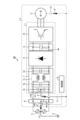
- FIG. 1 is a diagram showing a configuration example of an electrical device according to a first embodiment
- FIG. 1 is a diagram for explaining the operation of an electrical device according to a first embodiment
- 1 is a flowchart for explaining a method for detecting a connection state of a ground wire in an electric device according to a first embodiment
- FIG. 1 is a diagram showing an example of a hardware configuration for implementing the functions of a control unit included in an electrical device according to a first embodiment
- FIG. 1 is a diagram showing a configuration of a first modified example of a power conversion device in an electric device according to a first embodiment
- FIG. 1 is a diagram showing a configuration of a second modified example of a power conversion device in an electric device according to the first embodiment
- FIG. 13 is a diagram showing a configuration of a third modified example of a power conversion device in an electric device according to the first embodiment
- FIG. 13 is a diagram showing a configuration of a fourth modified example of a power conversion device in an electric device according to the first embodiment
- FIG. 13 is a diagram showing a configuration example of an electrical device according to a second embodiment
- 10 is a flowchart for explaining a method for detecting a connection state of a ground wire in an electric device according to a second embodiment.
- FIG. 13 is a diagram showing a configuration example of a refrigeration cycle device according to a third embodiment.
- connection will be used without distinguishing between physical connection and electrical connection.
- connection includes both cases where components are directly connected to each other and cases where components are indirectly connected to each other via other components.
- connection includes both cases where components are directly connected to each other and cases where components are indirectly connected to each other via other components.
- connection will be given using as an example a case where an electrical equipment is mounted in a refrigeration cycle apparatus, but is not limited to this example.
- technology of the present disclosure can also be applied to electrical equipment mounted in devices other than refrigeration cycle apparatus.
- FIG. 1 is a diagram showing a configuration example of an electric device 50 according to a first embodiment.
- the electric device 50 according to the first embodiment includes a terminal block 6, a noise filter circuit 7, a rectifier circuit 8, a smoothing unit 9, an inverter circuit 10, and a motor 11.
- the noise filter circuit 7, the rectifier circuit 8, the smoothing unit 9, and the inverter circuit 10 constitute a power conversion device that performs power conversion, and the circuit components of the power conversion device are mounted on a substrate 1.
- the substrate 1, the terminal block 6, and the motor 11 are accommodated in a housing 2.
- the smoothing unit 9 has a capacitor 9a as a smoothing element.
- the rectifier circuit 8 is, for example, a bridge circuit composed of four rectifier elements.
- the inverter circuit 10 is, for example, a three-phase bridge circuit composed of six semiconductor switching elements.
- the electrical equipment 50 is an outdoor unit of a refrigeration cycle device, and the motor 11 is a compressor drive motor. Although not shown, a fan drive motor is connected in parallel to the motor 11 to the inverter circuit 10. Also, in FIG. 1, the relay circuit, control power supply circuit, etc. are not shown.
- the terminal block 6 is connected to the AC power source 3, which is a power supply source.
- the midpoint 13 of the AC power source 3 is grounded to the earth ground 5.
- the housing 2 and the terminal block 6 are connected by an electric wiring 16a, and the terminal block 6 and the midpoint 13 of the AC power source 3 are connected by an electric wiring 16b.
- the potential of the housing 2 becomes the same as the earth potential, which is the potential of the earth ground 5, and the housing 2 is grounded to the earth ground 5.
- the electric wiring 16a may be called the "first ground wire” and the electric wiring 16b may be called the "earth wire”.
- FIG. 1 illustrates an example in which the AC power source 3 is a single-phase three-wire AC power source, the present invention is not limited to this example.
- the AC power source 3 may be a single-phase two-wire AC power source, a three-phase three-wire AC power source, or a three-phase four-wire AC power source.
- the noise filter circuit 7 has a first circuit section 7a having two line bypass capacitors connected in series, a second circuit section 7b having an across-the-line capacitor and arranged in the rear stage of the first circuit section 7a, a third circuit section 7c having two common mode chokes and arranged in the rear stage of the second circuit section 7b, and a fourth circuit section 7d having an across-the-line capacitor and arranged in the rear stage of the third circuit section 7c.
- the line bypass capacitor is also called a "Y capacitor”
- the across-the-line capacitor is also called an "X capacitor”.
- the connection point 18 of the two Y capacitors and the housing 2 are connected by an electrical wiring 17.
- the connection point 18 is electrically connected to the housing 2 and has the same potential as the earth potential.
- the electrical wiring 17 may be called the "second ground wire”.
- a power supply voltage is applied to the board 1 from the AC power supply 3 via the terminal block 6.
- the power supply voltage is applied to the rectifier circuit 8 via the noise filter circuit 7.
- the power supply voltage is rectified by the rectifier circuit 8, and the rectified voltage is smoothed by the smoothing section 9.
- the smoothed DC voltage is converted to an AC voltage of the desired voltage and frequency by the inverter circuit 10, and is applied to the motor 11 connected to the output terminal of the inverter circuit 10, driving the motor 11.
- the noise filter circuit 7 removes noise input from the AC power supply 3.
- the noise filter circuit 7 also removes high-frequency noise generated when the inverter circuit 10 performs switching operations.
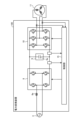
- FIG. 2 is a diagram used to explain the operation of the electrical device 50 according to the first embodiment.
- a current detector 14 and a control unit 15 are additionally illustrated as components for detecting whether the electrical wiring 16b, which is an earth wire, is connected to the electrical device 50 shown in FIG. 1.
- the current detector 14 is a sensor that detects the current flowing through the electrical wiring 16a. This type of sensor includes sensors that convert the current into a voltage or magnetic field for detection, but any sensor that can detect the current flowing through the electrical wiring 16a will do. In other words, the current detector 14 is a detector that detects a physical quantity that is correlated with the current flowing through the electrical wiring 16a. The detection value of the current detector 14 is input to the control unit 15.
- Common mode current 4 is a current that flows through electrical wiring 16b, which is the earth wire. Electrical wiring 16b is electrical wiring that is installed when an installation contractor performs wiring work. For this reason, if there is a mistake in the wiring work, common mode current 4 will not flow. Also, even if the installation is normal, common mode current 4 will stop flowing if the mounting part of the terminal block 6 to which electrical wiring 16b is connected becomes loose over time, causing the connection to become unstable.
- common mode current 4' is a current that flows through electrical wiring 17, which is the second ground line.
- the current that flows through electrical wiring 17 is a current that flows between substrate 1 and housing 2.
- common mode current 4" is a current that flows through parasitic capacitance 12 between motor 11 and housing 2.
- Common mode current 4 is the sum of multiple common mode currents including common mode current 4' and common mode current 4". If electrical wiring 16b is not connected or if the connection state of electrical wiring 16b is poor, common mode current 4 does not flow through electrical wiring 16b.
- the current detector 14 detects the current flowing through the electrical wiring 16a, which is the first ground wire. The same amount of current flows through the electrical wiring 16a as through the electrical wiring 16b. Because the current flowing through the electrical wiring 16a is small, a small-sized and small-capacity current detector 14 can be used. Furthermore, since the current detector 14 only needs to be able to detect whether or not a current flows through the electrical wiring 16b, the current detector 14 can be of any frequency band, and an inexpensive current sensor can be used.
- common mode current 4 common mode current 4', and common mode current 4" are all currents that flow through the housing 2, but even in places not shown, there are multiple common mode currents that flow through parasitic capacitance and other ground lines. Examples of other ground lines include a ground line that grounds a heat sink for cooling a switching element provided in the inverter circuit 10.
- the current detector 14 only needs to be positioned so that it can detect the common mode current that circulates through at least two of the AC power supply 3, the board 1, and the case 2.
- the first embodiment an example of the positioning of the current detector 14 that detects the current flowing between the AC power supply 3 and the case 2 was described, but in the second embodiment described below, other example positions will be described.
- Figure 3 is a flowchart for explaining the method for detecting the earth wire connection state in the electrical device 50 according to the first embodiment.
- the control unit 15 obtains the detection value of the common mode current 4 from the current detector 14 (step S11).
- the control unit 15 determines whether the detection value of the common mode current 4 is zero (step S12). Zero here includes the case where it is substantially zero, that is, the case where the detection value of the common mode current 4 is not exactly zero but is considered to be zero. If the detection value of the common mode current 4 is zero (step S12, Yes), the control unit 15 determines that the earth wire is disconnected (step S13). On the other hand, if the detection value of the common mode current 4 is not zero (step S12, No), the control unit 15 determines that the earth wire is not disconnected (step S14).
- the control unit 15 operates as a detection unit that detects whether the earth wire is connected or not based on the detection value of the current detector 14.
- the control unit 15 determines that the earth wire is disconnected and stops the operation of the electrical device 50, or notifies or displays that the electrical device 50 is abnormal, thereby notifying the user or administrator of warning information that there is an abnormality.
- the warning that there is an abnormality may be, for example, a buzzer sound, a lighted lamp, or a display on the display of a remote control.
- the electrical device 50 is connected to an information terminal such as a smartphone so that it can communicate with the information terminal, the information terminal may be notified.
- the electrical device 50 is an air conditioner, and the air conditioner is connected to a management company so that it can communicate with the Internet, the management company may be notified.
- the electrical equipment 50 is designed so that current flows through the electrical wiring 16b not only when the equipment is in operation but also when the equipment is not in operation, it is possible to determine whether the earth wire is connected even when the equipment 50 is not in operation.
- the control unit 15 can be configured as shown in FIG. 4.
- FIG. 4 is a diagram showing an example of a hardware configuration that realizes the functions of the control unit 15 provided in the electrical device 50 according to the first embodiment.
- the functions of the control unit 15 are realized by the processor 200 and the memory 202.
- the processor 200 is a CPU (also called a Central Processing Unit, processing unit, arithmetic unit, microprocessor, microcomputer, processor, or DSP (Digital Signal Processor)) or a system LSI (Large Scale Integration).
- Examples of the memory 202 include non-volatile or volatile semiconductor memories such as RAM (Random Access Memory), ROM (Read Only Memory), flash memory, EPROM (Erasable Programmable Read Only Memory), and EEPROM (registered trademark) (Electrically Erasable Programmable Read Only Memory).
- the memory 202 is not limited to these, and may be a magnetic disk, optical disk, compact disk, mini disk, or DVD (Digital Versatile Disc).
- the rectifier circuit 8 constituting the power conversion device has been described as a bridge circuit composed of, for example, four rectifier elements, but is not limited to this configuration.
- it may be configured as shown in Figs. 5 to 8.
- Figs. 5 to 8 are diagrams showing the configurations of first to fourth modified examples of the power conversion device inside the electric device 50 according to the first embodiment.
- the power conversion device portion in the electric device 50 is shown as the power conversion device 100.
- components equivalent to those shown in Figs. 1 and 2 are given the same reference numerals.
- the terminal block 6 and the noise filter circuit 7 are omitted from illustration.
- a reactor 8a may be inserted between the AC power supply 3 and the rectifier circuit 8.
- a boost circuit 8b may be provided between the rectifier circuit 8 and the smoothing unit 9.
- a reactor 8a may be inserted between the AC power supply 3 and the rectifier circuit 8, and the four rectifier elements constituting the rectifier circuit 8 may be switching elements.
- a short circuit 8c may be provided between the reactor 8a and the rectifier circuit 8 to short-circuit the power supply voltage applied to the rectifier circuit 8.
- the electric device is an electric device having a function of detecting whether or not the earth wire is connected, and includes a board on which circuit components of a power conversion device that performs power conversion are mounted and on which a power supply voltage is applied from a power supply source, and a housing that accommodates the board.
- the electric device also includes a detector that detects a physical quantity that is correlated with a common mode current that flows in a circulating manner through at least two of the power supply source, the board, and the housing due to the power generated by the power conversion device, and a detection unit that detects whether or not the earth wire is connected based on the detection value of the detector.
- the electric device according to the first embodiment configured in this manner does not require a leakage current breaker that may be provided in the conventional technology.
- the electric device according to the first embodiment also does not require an additional circuit such as a high-frequency generating circuit that was required in the conventional technology, and it is possible to prevent the occurrence of a malfunction in which the connection state of the earth wire cannot be correctly detected due to an abnormality in the additional circuit. This makes it possible to obtain an electric device that can correctly and reliably detect the connection state of the earth wire of the electric device while suppressing an increase in manufacturing costs.
- the electrical device also includes a first ground wire for electrically connecting the housing and the power supply source.
- the detector detects a physical quantity that is correlated with the current flowing through the first ground wire.
- the housing contains a terminal block that receives the power supply voltage and applies it to the board.
- the first ground wire is arranged to electrically connect the housing and the power supply source via the terminal block.
- the operation of the electrical device can be stopped, or a notification can be sent that the electrical device is abnormal. This allows the electrical device to be safely stopped, and also allows the user or administrator to be notified of information regarding a fault in the earth wire connection.
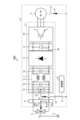
- FIG. 9 is a diagram showing a configuration example of an electric device 50A according to embodiment 2.
- the current detector 14 arranged on the electric wiring 16a in the configuration of the electric device 50 shown in Fig. 2 is deleted, and a current detector 14' is arranged on the electric wiring 17, which is the second ground wire.
- the other configuration is the same as or equivalent to the configuration in Fig. 2, and the same or equivalent components are denoted by the same reference numerals, and duplicated explanations will be omitted.
- the current detector 14' is a sensor that detects the current flowing between the connection point 18 of the two Y capacitors and the housing 2, i.e., the current flowing between the board 1 and the housing 2.
- This type of sensor includes sensors that convert the current into a voltage or magnetic field for detection, but any sensor that can detect the current flowing in the electrical wiring 17 will do.
- the current detector 14' is a detector that detects a physical quantity that is correlated with the current flowing in the electrical wiring 17.
- the detection value of the current detector 14' is input to the control unit 15.
- the common mode current 4' detected by the current detector 14' is different from the common mode current 4 flowing between the housing 2 and the AC power supply 3, but is a part of it. If the electrical wiring 16b, which is the earth wire, is not connected, or if the connection state of the electrical wiring 16b is poor, or if the connection state of the electrical wiring 16b becomes poor, the common mode current 4 will not flow through the electrical wiring 16b. In this case, the common mode current 4' flows through a different path that does not pass through the electrical wiring 16b, and the current that should flow through the electrical wiring 16b is added, so the common mode current 4' increases. However, it is also possible that the common mode current 4' will decrease due to a change in the capacitance of the parasitic capacitance 12. In either case, if the correlation between the common mode current 4 and the common mode current 4' is investigated in advance, the common mode current 4' can be used indirectly to estimate the common mode current 4.
- Figure 10 is a flowchart for explaining a method for detecting the earth wire connection state in electrical device 50A according to embodiment 2.
- the control unit 15 obtains and monitors the detection value of the common mode current 4' from the current detector 14' (step S21). The control unit 15 determines whether the detection value of the common mode current 4' exceeds a threshold value or has changed across the threshold value (step S22). The threshold value can be determined based on the correlation between the common mode current 4 and the common mode current 4' previously investigated. If the detection value of the common mode current 4' exceeds the threshold value or has changed across the threshold value (step S22, Yes), the control unit 15 determines that the earth wire is disconnected (step S23). If the detection value of the common mode current 4' does not exceed the threshold value and has not changed across the threshold value (step S22, No), the control unit 15 determines that the earth wire is not disconnected (step S24).
- the control unit 15 operates as a detection unit that detects whether the earth wire is connected or not based on the detection value of the current detector 14'. If the detection value of the current detector 14' exceeds the threshold, the control unit 15 determines that the earth wire is disconnected and stops the operation of the electrical device 50A, or notifies or displays that the electrical device 50A is abnormal, thereby notifying the user or administrator of the abnormality.
- the abnormality warning may be, for example, a buzzer sound, a lighted lamp, or a display on the display of a remote control. If the electrical device 50A is connected to an information terminal such as a smartphone so that it can communicate with the information terminal, the information terminal may be notified. If the electrical device 50A is an air conditioner, and the air conditioner is connected to a management company so that it can communicate with the management company via the Internet, the management company may be notified.
- the electrical equipment 50A is designed so that current flows through the electrical wiring 17 not only when the equipment is operating but also when the equipment is stopped, it is possible to determine whether the earth wire is connected even when the equipment 50A is stopped.
- the electrical device according to the second embodiment includes a second ground wire for electrically connecting the housing and the board.
- the detector detects a physical quantity that is correlated with the current flowing through the second ground wire.
- the housing accommodates a terminal block that receives the power supply voltage and applies it to the board.
- the electrical device according to the second embodiment does not require an additional circuit such as a high-frequency generating circuit that was required in the conventional technology, and it is possible to prevent the occurrence of a malfunction in which the connection state of the earth wire cannot be correctly detected due to an abnormality in the additional circuit. This makes it possible to obtain an electrical device that can correctly and reliably detect the connection state of the earth wire of the electrical device while suppressing an increase in manufacturing costs.
- the operation of the electrical device can be stopped, or a notification can be sent that the electrical device is abnormal. This allows the electrical device to be safely stopped, and also allows the user or administrator to be notified of information regarding a fault in the earth wire connection.
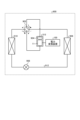
- Embodiment 3. 11 is a diagram showing a configuration example of a refrigeration cycle apparatus 900 according to embodiment 3.
- the refrigeration cycle apparatus 900 according to embodiment 3 includes the power conversion apparatus 100 described in embodiment 1.
- the refrigeration cycle apparatus 900 according to embodiment 3 can be applied to products including a refrigeration cycle, such as air conditioners, refrigerators, freezers, and heat pump water heaters.
- the refrigeration cycle device 900 includes a compressor 315 incorporating the motor 11 in the first embodiment, a four-way valve 902, an indoor heat exchanger 906, an expansion valve 908, and an outdoor heat exchanger 910, which are attached via refrigerant piping 912.
- a compression mechanism 904 that compresses the refrigerant, and a motor 11 that operates the compression mechanism 904.
- the refrigeration cycle device 900 can perform heating or cooling operation by switching the four-way valve 902.
- the compression mechanism 904 is driven by a variable speed controlled motor 11.
- the refrigerant is pressurized by the compression mechanism 904 and sent out, passes through the four-way valve 902, the indoor heat exchanger 906, the expansion valve 908, the outdoor heat exchanger 910, and the four-way valve 902, and returns to the compression mechanism 904.
- the refrigerant is pressurized by the compression mechanism 904 and sent out, passes through the four-way valve 902, the outdoor heat exchanger 910, the expansion valve 908, the indoor heat exchanger 906, and the four-way valve 902, and returns to the compression mechanism 904.
- the indoor heat exchanger 906 acts as a condenser to release heat, and the outdoor heat exchanger 910 acts as an evaporator to absorb heat.
- the outdoor heat exchanger 910 acts as a condenser to release heat, and the indoor heat exchanger 906 acts as an evaporator to absorb heat.
- the expansion valve 908 reduces the pressure of the refrigerant to expand it.
- the refrigerants used in the refrigeration cycle device 900 are, for example, R1234yf, R1234ze(E), R1243zf, HFO1123, HFO1132(E), R1132a, CF3I, R290, R463A, R466A, R454A, R454B, R454C, etc.
- the internal capacitance components of the compressor 315 differ depending on the type of refrigerant, so there is a correlation between the type of refrigerant and the common mode currents 4, 4'. For this reason, it is desirable to investigate the correlation between the type of refrigerant and the common mode currents 4, 4' in advance.
- the refrigeration cycle device 900 according to embodiment 3 can be equipped with the electrical device 50 according to embodiment 1 and the electrical device 50A according to embodiment 2, and can therefore enjoy the effects obtained in embodiments 1 and 2.
- examples of refrigerants that can be used in the refrigeration cycle device 900 according to the third embodiment include the above-mentioned R1234yf, R1234ze(E), R1243zf, HFO1123, HFO1132(E), R1132a, CF3I, R290, R463A, R466A, R454A, R454B, and R454C.
- These refrigerants have many uses, and it is useful to obtain the volumetric components of these refrigerants in advance. In this way, an appropriate threshold value can be set according to the type of refrigerant, which contributes to improving the detection accuracy of detecting whether the earth wire is connected or not.
- Parasitic Capacity 13 midpoint, 14, 14' current detector, 15 control unit, 16a, 16b, 17 electrical wiring, 18 connection point, 50, 50A electrical equipment, 100 power conversion device, 200 processor, 202 memory, 315 compressor, 900 refrigeration cycle device, 902 four-way valve, 904 compression mechanism, 906 indoor heat exchanger, 908 expansion valve, 910 outdoor heat exchanger, 912 refrigerant piping.
Landscapes
- Physics & Mathematics (AREA)
- General Physics & Mathematics (AREA)
- Inverter Devices (AREA)
- Emergency Protection Circuit Devices (AREA)
Abstract
Description
図1は、実施の形態1に係る電気機器50の構成例を示す図である。実施の形態1に係る電気機器50は、図1に示すように、端子台6と、ノイズフィルタ回路7と、整流回路8と、平滑部9と、インバータ回路10と、モータ11とを備える。ノイズフィルタ回路7、整流回路8、平滑部9及びインバータ回路10は電力変換を行う電力変換装置を構成し、電力変換装置の回路部品は基板1に搭載される。基板1、端子台6及びモータ11は、筐体2に収容される。平滑部9は、平滑素子としてコンデンサ9aを有する。整流回路8は、例えば4つの整流素子から構成されるブリッジ回路である。インバータ回路10は、例えば6つの半導体スイッチング素子から構成される三相ブリッジ回路である。
図9は、実施の形態2に係る電気機器50Aの構成例を示す図である。図9に示す電気機器50Aでは、図2に示す電気機器50の構成において、電気配線16aに配置されていた電流検出器14が削除される一方で、第2の接地線である電気配線17に電流検出器14’が配置されている。その他の構成は、図2の構成と同一又は同等であり、同一又は同等の構成要素には同一の符号を付して示すと共に、重複する説明は割愛する。
図11は、実施の形態3に係る冷凍サイクル装置900の構成例を示す図である。実施の形態3に係る冷凍サイクル装置900は、実施の形態1で説明した電力変換装置100を備える。実施の形態3に係る冷凍サイクル装置900は、空気調和機、冷蔵庫、冷凍庫、ヒートポンプ給湯器といった冷凍サイクルを備える製品に適用することが可能である。
Claims (9)
- アース線が接続されているか否かを検知する機能を有する電気機器であって、
電力変換を行う電力変換装置の回路部品が搭載され、電力供給源から電源電圧が印加される基板と、
前記基板を収容する筐体と、
前記電力変換装置が発生させた電力によって、前記電力供給源、前記基板及び前記筐体のうちの少なくとも2箇所を循環するように流れるコモンモード電流と相関のある物理量を検出する検出器と、
前記検出器の検出値に基づいて前記アース線の接続の有無を検知する検知部と、
を備える電気機器。 - 前記電気機器は、前記筐体と前記電力供給源との間を電気的に接続するための第1の接地線を備え、
前記検出器は、前記第1の接地線に流れる電流と相関のある物理量を検出する
請求項1に記載の電気機器。 - 前記筐体には、前記電源電圧を受電して前記基板に印加する端子台が収容され、
前記第1の接地線は、前記端子台を介して前記筐体と前記電力供給源との間を電気的に接続するように配される
請求項2に記載の電気機器。 - 前記検出器の検出値がゼロである場合、前記電気機器の動作を停止させる、又は前記電気機器が異常である旨を通知する
請求項2又は3に記載の電気機器。 - 前記電気機器は、前記筐体と前記基板との間を電気的に接続するための第2の接地線を備え、
前記検出器は、前記第2の接地線に流れる電流と相関のある物理量を検出する
請求項1に記載の電気機器。 - 前記基板には、Yコンデンサを含むノイズフィルタが搭載され、
前記第2の接地線は、前記筐体と前記Yコンデンサとの間に配される
請求項5に記載の電気機器。 - 前記検出器の検出値が閾値を超過している場合、又は前記閾値を跨いで変化した場合、前記電気機器の動作を停止させる、又は前記電気機器が異常である旨を通知する
請求項5又は6に記載の電気機器。 - 請求項1から7の何れか1項に記載の電気機器を備える冷凍サイクル装置。
- 前記冷凍サイクル装置で使用される冷媒は、R1234yf、R1234ze(E)、R1243zf、HFO1123、HFO1132(E)、R1132a、CF3I、R290、R463A、R466A、R454A、R454B、R454Cの何れかである
請求項8に記載の冷凍サイクル装置。
Priority Applications (2)
| Application Number | Priority Date | Filing Date | Title |
|---|---|---|---|
| PCT/JP2023/006247 WO2024176355A1 (ja) | 2023-02-21 | 2023-02-21 | 電気機器及び冷凍サイクル装置 |
| US18/580,441 US12379427B2 (en) | 2023-02-21 | 2023-02-21 | Electrical apparatus and refrigeration cycler |
Applications Claiming Priority (1)
| Application Number | Priority Date | Filing Date | Title |
|---|---|---|---|
| PCT/JP2023/006247 WO2024176355A1 (ja) | 2023-02-21 | 2023-02-21 | 電気機器及び冷凍サイクル装置 |
Publications (1)
| Publication Number | Publication Date |
|---|---|
| WO2024176355A1 true WO2024176355A1 (ja) | 2024-08-29 |
Family
ID=92500417
Family Applications (1)
| Application Number | Title | Priority Date | Filing Date |
|---|---|---|---|
| PCT/JP2023/006247 Ceased WO2024176355A1 (ja) | 2023-02-21 | 2023-02-21 | 電気機器及び冷凍サイクル装置 |
Country Status (2)
| Country | Link |
|---|---|
| US (1) | US12379427B2 (ja) |
| WO (1) | WO2024176355A1 (ja) |
Citations (6)
| Publication number | Priority date | Publication date | Assignee | Title |
|---|---|---|---|---|
| JPS6243576A (ja) * | 1985-08-20 | 1987-02-25 | Taga Denki Kk | 電子応用機器のア−ス検出回路 |
| JPH08184626A (ja) * | 1994-12-28 | 1996-07-16 | Nippon Signal Co Ltd:The | 接地線断線検出装置及び接地線断線検出装置を有する電気・電子機器 |
| WO2008044593A1 (fr) * | 2006-10-05 | 2008-04-17 | Max Co., Ltd. | Dispositif de surveillance de connexion à une ligne de mise à la masse et dispositif électrique |
| JP2010054468A (ja) * | 2008-08-29 | 2010-03-11 | Sanyo Electric Co Ltd | 車両用の電源装置 |
| WO2014102954A1 (ja) * | 2012-12-27 | 2014-07-03 | 新電元工業株式会社 | 電気機器、および、アース確認方法 |
| WO2019123673A1 (ja) * | 2017-12-19 | 2019-06-27 | 馬鞍山市明珠電子科技有限公司 | 電気機器及び電気機器の接地状態検知方法 |
Family Cites Families (10)
| Publication number | Priority date | Publication date | Assignee | Title |
|---|---|---|---|---|
| US4329643A (en) * | 1980-03-13 | 1982-05-11 | Neumann Manfred H | Portable circuit testing system |
| JP2534938Y2 (ja) | 1990-06-28 | 1997-05-07 | 株式会社ゼクセル | アース異常検出装置 |
| JP3338587B2 (ja) * | 1995-07-19 | 2002-10-28 | 日本信号株式会社 | 漏電検出器 |
| US5949197A (en) * | 1997-06-30 | 1999-09-07 | Everbrite, Inc. | Apparatus and method for dimming a gas discharge lamp |
| JP2006250782A (ja) | 2005-03-11 | 2006-09-21 | Mitsubishi Electric Corp | アース線接続検知装置 |
| JP5180680B2 (ja) * | 2008-05-20 | 2013-04-10 | サンデン株式会社 | 冷凍サイクル |
| DE102014210290A1 (de) * | 2014-05-30 | 2015-12-03 | Bender Gmbh & Co. Kg | Verfahren und vorrichtung zur überwachung einer schutzleiterverbindung |
| DE112016002693T5 (de) * | 2015-07-08 | 2018-03-08 | Kelsey-Hayes Company | Masseverlustdetektionsschaltung |
| WO2022118450A1 (ja) | 2020-12-03 | 2022-06-09 | 三菱電機株式会社 | 電力変換装置、モータ駆動システム、及び信号伝送用ケーブルの断線検出方法 |
| DE102021112808A1 (de) * | 2021-05-18 | 2022-11-24 | Schaeffler Technologies AG & Co. KG | Elektrische Schaltungsanordnung und Verfahren zur Detektion eines Kurzschlusses |
-
2023
- 2023-02-21 WO PCT/JP2023/006247 patent/WO2024176355A1/ja not_active Ceased
- 2023-02-21 US US18/580,441 patent/US12379427B2/en active Active
Patent Citations (6)
| Publication number | Priority date | Publication date | Assignee | Title |
|---|---|---|---|---|
| JPS6243576A (ja) * | 1985-08-20 | 1987-02-25 | Taga Denki Kk | 電子応用機器のア−ス検出回路 |
| JPH08184626A (ja) * | 1994-12-28 | 1996-07-16 | Nippon Signal Co Ltd:The | 接地線断線検出装置及び接地線断線検出装置を有する電気・電子機器 |
| WO2008044593A1 (fr) * | 2006-10-05 | 2008-04-17 | Max Co., Ltd. | Dispositif de surveillance de connexion à une ligne de mise à la masse et dispositif électrique |
| JP2010054468A (ja) * | 2008-08-29 | 2010-03-11 | Sanyo Electric Co Ltd | 車両用の電源装置 |
| WO2014102954A1 (ja) * | 2012-12-27 | 2014-07-03 | 新電元工業株式会社 | 電気機器、および、アース確認方法 |
| WO2019123673A1 (ja) * | 2017-12-19 | 2019-06-27 | 馬鞍山市明珠電子科技有限公司 | 電気機器及び電気機器の接地状態検知方法 |
Also Published As
| Publication number | Publication date |
|---|---|
| US20250076406A1 (en) | 2025-03-06 |
| US12379427B2 (en) | 2025-08-05 |
Similar Documents
| Publication | Publication Date | Title |
|---|---|---|
| US8164292B2 (en) | Motor controller of air conditioner | |
| KR100320699B1 (ko) | 증기라인압력제어 | |
| AU2010238133B2 (en) | Power circuit, and computer-readable recording medium storing a control program for power circuits | |
| CN112787565B (zh) | 用于包括制冷剂泄漏缓解的hvac系统的冗余功率供给 | |
| KR101395890B1 (ko) | 공기조화기의 전동기 제어장치 및 그 제어 방법 | |
| CN101197532A (zh) | 冷冻装置及用于冷冻装置的逆变装置 | |
| KR101482101B1 (ko) | 공기조화기 | |
| US12123605B2 (en) | Sensor system for leak detection and management in heating, ventilating, and air conditioning (HVAC) systems | |
| CN107078657A (zh) | 功率转换装置 | |
| WO2009057866A2 (en) | Method for controlling motor of air conditioner and motor controller of the same | |
| KR20100012077A (ko) | 공기조화기의 전동기 제어장치 | |
| WO2024176355A1 (ja) | 電気機器及び冷凍サイクル装置 | |
| US20230296302A1 (en) | Device management system for inverter compressor | |
| JP4623220B2 (ja) | 電源回路 | |
| WO2022137456A1 (ja) | 電力変換装置および空気調和機 | |
| JP2000324696A (ja) | 空気調和装置 | |
| JP7395029B2 (ja) | 電力変換装置及び空気調和装置 | |
| AU2020424325B2 (en) | Heat pump device, heat pump system, air conditioner, and refrigeration machine | |
| JP7198344B2 (ja) | 直流電源装置、モータ駆動装置、空気調和装置、冷蔵庫およびヒートポンプ給湯装置 | |
| WO2020008620A1 (ja) | 冷凍サイクル装置および空気調和装置 | |
| KR100395945B1 (ko) | 인버터 공기조화기의 캐리어주파수제어방법 | |
| JP2018125997A (ja) | 空気調和機 | |
| US20260002685A1 (en) | Refrigerant Sensor Integration into Climate Control Systems | |
| JP7487691B2 (ja) | モータ制御装置及び空気調和機 | |
| WO2021171414A1 (ja) | 電力変換装置 |
Legal Events
| Date | Code | Title | Description |
|---|---|---|---|
| WWE | Wipo information: entry into national phase |
Ref document number: 18580441 Country of ref document: US |
|
| 121 | Ep: the epo has been informed by wipo that ep was designated in this application |
Ref document number: 23924009 Country of ref document: EP Kind code of ref document: A1 |
|
| WWP | Wipo information: published in national office |
Ref document number: 18580441 Country of ref document: US |
|
| WWG | Wipo information: grant in national office |
Ref document number: 18580441 Country of ref document: US |
|
| NENP | Non-entry into the national phase |
Ref country code: DE |
|
| 122 | Ep: pct application non-entry in european phase |
Ref document number: 23924009 Country of ref document: EP Kind code of ref document: A1 |
|
| NENP | Non-entry into the national phase |
Ref country code: JP |