WO2024176353A1 - データ収集装置、及びプログラムを記録したコンピュータ読み取り可能な記録媒体 - Google Patents
データ収集装置、及びプログラムを記録したコンピュータ読み取り可能な記録媒体 Download PDFInfo
- Publication number
- WO2024176353A1 WO2024176353A1 PCT/JP2023/006232 JP2023006232W WO2024176353A1 WO 2024176353 A1 WO2024176353 A1 WO 2024176353A1 JP 2023006232 W JP2023006232 W JP 2023006232W WO 2024176353 A1 WO2024176353 A1 WO 2024176353A1
- Authority
- WO
- WIPO (PCT)
- Prior art keywords
- data
- load
- collection
- timing
- acquisition
- Prior art date
- Legal status (The legal status is an assumption and is not a legal conclusion. Google has not performed a legal analysis and makes no representation as to the accuracy of the status listed.)
- Ceased
Links
Images




Classifications
-
- G—PHYSICS
- G05—CONTROLLING; REGULATING
- G05B—CONTROL OR REGULATING SYSTEMS IN GENERAL; FUNCTIONAL ELEMENTS OF SUCH SYSTEMS; MONITORING OR TESTING ARRANGEMENTS FOR SUCH SYSTEMS OR ELEMENTS
- G05B19/00—Program-control systems
- G05B19/02—Program-control systems electric
- G05B19/418—Total factory control, i.e. centrally controlling a plurality of machines, e.g. direct or distributed numerical control [DNC], flexible manufacturing systems [FMS], integrated manufacturing systems [IMS] or computer integrated manufacturing [CIM]
-
- G—PHYSICS
- G06—COMPUTING OR CALCULATING; COUNTING
- G06Q—INFORMATION AND COMMUNICATION TECHNOLOGY [ICT] SPECIALLY ADAPTED FOR ADMINISTRATIVE, COMMERCIAL, FINANCIAL, MANAGERIAL OR SUPERVISORY PURPOSES; SYSTEMS OR METHODS SPECIALLY ADAPTED FOR ADMINISTRATIVE, COMMERCIAL, FINANCIAL, MANAGERIAL OR SUPERVISORY PURPOSES, NOT OTHERWISE PROVIDED FOR
- G06Q50/00—Information and communication technology [ICT] specially adapted for implementation of business processes of specific business sectors, e.g. utilities or tourism
- G06Q50/04—Manufacturing
Definitions
- This disclosure relates to a data collection device and a computer-readable recording medium having a program recorded thereon.
- a device that collects data from industrial machinery in this way is called a data collection device.
- recent data collection devices also use communication functions to send and receive data with external devices and provide a visual user interface. For example, data collection devices collect data at predetermined times or when a specific event occurs.
- the load on the control device varies depending on the block of the control program that is executed.
- the load and time required for the acquisition process vary depending on the type of data.
- the desired acquisition period varies depending on the type of data. In manufacturing sites, there is a demand for technology that can collect data while reducing the burden associated with data acquisition.
- the data collection device disclosed herein solves the above problem by estimating the load on the control device from which data is collected and collecting data in a way that distributes the load.
- One aspect of the present disclosure includes a data acquisition time measurement unit that acquires various data from a control device that controls an industrial machine at a timing when a control program is not being executed and measures a time required to acquire the data; a data acquisition load calculation unit that calculates a load on the control device due to the acquisition of various data based on the time required to acquire the various data measured by the data acquisition time measurement unit; an operation-time acquisition time measurement unit that acquires a block number of the control program being executed from the control device while the industrial machine is operating based on the control program and measures the time required to acquire data related to the block number; an operation-time load calculation unit that calculates a load at the time of execution of each block of the control program based on the time required to acquire data related to the block number measured by the operation-time acquisition time measurement unit; and a collection time calculation unit that determines a collection timing of the various data so that a predetermined loss calculated based on the load on the control device and a delay in data acquisition timing is small based on the load at the time of execution of
- FIG. 2 is a schematic hardware configuration diagram of a control device according to an embodiment of the present disclosure.
- FIG. 2 is a block diagram showing schematic functions of a control device according to the first embodiment.
- 11 is a table illustrating an example of an average time taken to acquire various data and a load value.
- FIG. 10 is a table illustrating an example of the average time taken to acquire data when each block of a control program is executed during operation of an industrial machine, and the average execution time of the block.
- FIG. 10 is a table illustrating load values at the time of execution of each block of a control program when an industrial machine is in operation.
- FIG. 11 is a graph showing the relationship between the transition of the load value during execution of each block of the control program and the timing of acquiring the servo load and alert information.
- FIG. 11 is a block diagram showing schematic functions of a control device according to a second embodiment.
- FIG. 11 is a block diagram showing schematic functions of a control device according to a third embodiment.
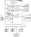
- FIG. 1 is a schematic hardware configuration diagram showing a main part of a data collection device according to a first embodiment of the present disclosure.
- the data collection device 1 can be implemented on a computer such as a personal computer attached to a control device that controls an industrial machine based on a control program, a personal computer connected to the control device via a wired/wireless network, a cell computer, a fog computer 6, or a cloud server 7.
- a computer such as a personal computer attached to a control device that controls an industrial machine based on a control program
- a personal computer connected to the control device via a wired/wireless network such as a cell computer, a fog computer 6, or a cloud server 7.
- an example is shown in which the data collection device 1 is implemented on a personal computer connected to a control device that controls an industrial machine via a network.
- the CPU 11 provided in the data collection device 1 is a processor that controls the entire data collection device 1.
- the CPU 11 reads the system program stored in the ROM 12 via the bus 22, and controls the entire data collection device 1 according to the system program.
- the RAM 13 temporarily stores temporary calculation data, display data, and various data acquired from outside.
- the interface 15 is an interface for connecting the CPU 11 of the data collection device 1 to an external device 72 such as a USB device.
- an external device 72 such as a USB device.
- system programs, setting data, etc. are read from the external device 72.
- programs and setting data created and edited within the data collection device 1 can be stored in an external storage means via the external device 72.
- the interface 20 is an interface for connecting the CPU 11 of the data collection device 1 to a wired or wireless network 5.
- the network 5 may communicate using technologies such as serial communication such as RS-485, Ethernet (registered trademark), optical communication, wireless LAN, Wi-Fi (registered trademark), Bluetooth (registered trademark), etc.
- serial communication such as RS-485, Ethernet (registered trademark), optical communication, wireless LAN, Wi-Fi (registered trademark), Bluetooth (registered trademark), etc.
- At least one industrial machine 4 to be controlled, at least one other industrial machine 4, a fog computer 6, a cloud server 7, etc. are connected to the network 5, and data is exchanged between the data collection device 1 and the network 5.
- the display device 70 displays the various data loaded into the memory, data obtained as a result of executing programs, etc., output via the interface 17.
- the input device 71 which is comprised of a keyboard, pointing device, etc., passes instructions and data based on operations by the operator to the CPU 11 via the interface 18.
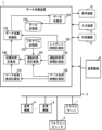
- FIG. 2 is a schematic block diagram showing the functions of the data collection device 1 according to the first embodiment of the present disclosure.
- Each function of the data collection device 1 according to this embodiment is realized by the CPU 11 of the data collection device 1 shown in FIG. 1 executing a system program and controlling the operation of each part of the data collection device 1.
- the data collection device 1 of this embodiment includes a data acquisition time measurement unit 100, a data acquisition load calculation unit 110, an operation acquisition time measurement unit 120, an operation load calculation unit 130, a collection time calculation unit 140, and a data collection unit 150.
- the RAM 13 to the non-volatile memory 14 of the data collection device 1 also include a program storage unit 210, which is an area for storing in advance a control program for controlling the industrial machine 4, and a data storage unit 220, which is an area for storing collected data.
- the data acquisition load calculation unit 110 calculates the load value related to the acquisition of various data from the control device based on the average time taken to acquire each data input from the data acquisition time measurement unit 100.
- the data acquisition load calculation unit 110 calculates the load value assuming that the longer the time taken to acquire the data, the higher the load related to the data acquisition.
- the load value related to the data acquisition may be a relative load value based on a predetermined reference value. For example, it may be a relative load value based on the load value expected when acquiring predetermined data (such as a block number) from the control device.
- the data acquisition load calculation unit 110 outputs the calculated load value related to the acquisition of various data to the collection time calculation unit 140.
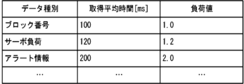
- FIG. 3 is a table illustrating the average time and load value required to acquire various data.
- the data acquisition time measurement unit 100 attempts to acquire various data such as block numbers, servo loads, and alert information.
- the average time measured to acquire data related to block numbers is 100 ms
- the average time measured to acquire data related to servo loads is 120 ms
- the average time measured to acquire data related to alert information is 200 ms.
- the load value is calculated assuming that the longer the average acquisition time, the higher the load value.
- the load value when acquiring block numbers is set to a reference value of 1.0, and the load values related to the acquisition of other data are calculated.
- the operation time acquisition measurement unit 120 repeatedly acquires block numbers of the control program from the control device that controls the industrial machine 4 while the industrial machine 4 is operating based on the control program. This process may be performed, for example, during a test run of the industrial machine 4 based on the control program. At this time, the operation time acquisition measurement unit 120 repeatedly acquires block numbers at a cycle (e.g., 10 ms) that is short enough to grasp changes in the block number during execution. Then, based on the block number acquisition results, the operation time acquisition measurement unit 120 measures the average time required to acquire data for each block number and the average time required from the start to the end of the block. The operation time acquisition measurement unit 120 outputs the measured average time required to acquire data for each block number and the average time required from the start to the end of the block to the operation load calculation unit 130.
- a cycle e.g. 10 ms
- FIG. 4 is a table diagram illustrating the average time it takes to acquire data when each block of the control program is executed while the industrial machine 4 is operating, and the average execution time of the blocks.
- it takes an average of 120 ms from when a request to acquire a block number is sent during execution of block number 1 until the block number is actually acquired. It also takes an average of 30 ms from when execution of block number 1 begins until it ends. This means that, for example, when block number acquisition is repeated at a cycle of 10 ms, a response indicating block number 1 is acquired three times on average.
- the load calculation unit 130 calculates the load value during execution of each block of the control program based on the time (average value) taken to acquire data related to the block number input from the data acquisition time measurement unit 100 and the time (average value) taken to acquire data related to the block number input from the operation acquisition time measurement unit 120.
- the load value during execution of each block is calculated assuming that the longer the time taken to acquire data, the higher the load.
- the load value during execution of each block may be a relative load value based on a predetermined reference value. For example, the time taken to acquire data when the industrial machine 4 is not operating is considered to correspond to a no-load state (load value 0%).
- the case where the average time taken to acquire data while the control program is being executed is the longest is considered to correspond to a maximum load state (load value 100%). Then, the time taken to acquire data in a no-load state and the time taken to acquire data in a maximum load state are used as reference values, and the load value is calculated from the ratio of the data acquisition times for each block number.
- the operating load calculation unit 130 outputs the calculated load value during execution of each block to the collection time calculation unit 140.
- FIG. 5 is a table showing an example of the load value when each block of the control program is executed while the industrial machine 4 is in operation.
- the time (100 ms) taken to acquire data related to the block number when the control program is not being executed is regarded as the data acquisition time in a no-load state (load value 0%).
- the average time (200 ms) taken to acquire data related to block number 3, which took the longest time to acquire data related to the block number while the control program is being executed, is regarded as the data acquisition time in a maximum load state (load value 100%).
- the load value is determined according to the ratio of the time taken to acquire data between 100 ms and 200 ms.
- block number 2 when block number 2 is being executed, it takes only 150 ms to acquire data. This is exactly halfway between 100 ms in a no-load state and 200 ms in a maximum load state, so the load value during execution of block number 2 can be calculated as 50%.
- the collection time calculation unit 140 determines the timing at which data is collected based on a predetermined evaluation value. For example, a predetermined loss calculated based on the load on the control device and the delay in the data acquisition timing can be used as the predetermined evaluation value.
- the following formula 1 shows an example of a loss function Loss(t) that calculates the predetermined loss based on the load on the control device and the delay in the data acquisition timing.
- the collection time calculation unit 140 may determine the acquisition timing of each piece of data so that the loss calculated by the loss function set in this way is approximately minimized.
- the first term represents the loss due to a delay in the timing of acquiring data.
- the second term represents the loss due to the load generated by acquiring data. If the timing of acquiring data is important, the coefficient ⁇ should be set to a large value, and if the importance is placed on suppressing the load on the control device, the coefficient ⁇ should be set to a large value.
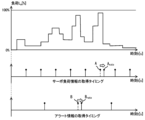
- FIG. 6 is a graph showing the relationship between the transition of the load value during execution of each block of the control program calculated by the load calculation unit 130 during operation and the timing of acquiring the preset servo load and alert information.
- the servo load information and the alert information are set to be acquired periodically at a predetermined cycle. If the timing of acquiring each data is not changed, the loss calculated by the first term of the loss function Loss(t) illustrated in the formula 1 will be 0. On the other hand, when focusing on the second term of the loss function Loss(t), in the example of FIG.
- the load value L p applied to the execution of the control program at the timing A of acquiring the servo load information is a very large value.
- the load value L p applied to the execution of the control program at the timing B of acquiring the alert information is also a large value. Therefore, at these acquisition timings, the loss calculated by the second term in the formula 1 will be large.
- the collection time calculation unit 140 delays the acquisition of servo load information that should have been performed at timing A until the load value Lp applied to the execution of the control program decreases. If the timing of collecting data is delayed from the timing at which it should have been acquired, the loss calculated by the first term of formula 1 increases. However, if the timing is delayed until the load value Lp applied to the execution of the control program decreases, the loss calculated by the second term of formula 1 may decrease.
- FIG. 7 shows a graph in the case where the acquisition of servo load information at timing A is delayed until timing A rate .
- the load value Lp applied to the execution of the control program at the acquisition timing is significantly reduced. Therefore, while the loss calculated by the first term of formula 1 increases due to the delay in timing, the loss calculated by the second term of formula 1 is significantly reduced by acquiring data at a timing when the load value Lp is low.
- FIG 8 shows a graph in the case where acquisition of the alert information at timing B is further delayed until timing B rate .
- delaying acquisition of the alert information at timing B increases the loss calculated by the first term of Equation 1, whereas acquiring data at a timing when the load value Lp is low significantly reduces the loss calculated by the second term of Equation 1.
- the collection time calculation unit 140 checks whether there is a timing at which the calculated loss will be smaller if the data acquisition timing is delayed within a specified range for each data acquisition timing. If there is a timing at which the loss can be reduced, the data acquisition timing is delayed.
- the data collection unit 150 collects specific data from the control device while the industrial machine 4 is in operation, at the timing calculated by the collection time calculation unit 140.
- the data collection unit 150 may start collecting various data, for example, from the point in time when the control device notifies the industrial machine 4 that it has started operating based on a control program.
- the data collection unit 150 stores the collected data in the data storage unit 220.
- the data collection device 1 which has the above configuration, collects various data taking into account the load state of each control device when a control program is being executed in the control device of each industrial machine 4.
- the data collection timing can be determined taking into account not only the load state of the control device, but also the delay from the original data collection timing.
- the data collecting device 1 according to the second embodiment will be described below.
- the data collecting device 1 according to the present embodiment determines the data acquisition timing taking into consideration data retransmissions and losses due to delays in data processing caused when data responses from the respective control devices arrive at the data collecting device 1 simultaneously.
- FIG. 9 is a schematic block diagram showing the functions of the data collection device 1 according to the second embodiment of the present disclosure.
- Each function of the data collection device 1 according to this embodiment is realized by the CPU 11 of the data collection device 1 shown in FIG. 1 executing a system program and controlling the operation of each part of the data collection device 1.
- the data collection device 1 of this embodiment includes a data acquisition time measurement unit 100, a data acquisition load calculation unit 110, an operation acquisition time measurement unit 120, an operation load calculation unit 130, a collection time calculation unit 140, and a data collection unit 150, as well as a response time measurement unit 160 and a data collection control unit 170.
- the RAM 13 to the non-volatile memory 14 of the data collection device 1 also include a program storage unit 210, which is an area for storing in advance a control program for controlling the industrial machine 4, and a data storage unit 220, which is an area for storing collected data.
- the data acquisition time measurement unit 100, data acquisition load calculation unit 110, driving acquisition time measurement unit 120, driving load calculation unit 130, and collection time calculation unit 140 according to this embodiment have the same functions as the data acquisition time measurement unit 100, data acquisition load calculation unit 110, driving acquisition time measurement unit 120, driving load calculation unit 130, and collection time calculation unit 140 according to the first embodiment.
- the response time measurement unit 160 measures the time for each block from when a request is made to the control device to acquire various data until a response is returned when the industrial machine 4 is operating according to the control program. This process may be performed, for example, during a test run of the industrial machine 4 based on the control program.
- the response time measurement unit 160 requests various data from the control device of the industrial machine 4 during execution of each block, for example when the control device is executing a control program.
- the response time measurement unit 160 measures the response time, which is the time it takes to receive data in response. By repeating this process, the response time measurement unit 160 measures the average response time for various data for each control program block.
- the response time measurement unit 160 outputs the average value of the measured response times to the data collection control unit 170.
- the data collection control unit 170 determines the timing of data collection based on a predetermined evaluation value calculated from the response time in acquiring various data measured by the response time measurement unit 160 and the collection timing of various data calculated by the collection time calculation unit 140.
- the predetermined evaluation value can be a predetermined loss calculated based on the load on the control device, the delay in the data acquisition timing, and the delay in data retransmission or data processing caused by simultaneous data responses (collision).
- the following formula 2 shows an example of a loss function Loss2(t) that calculates a predetermined loss based on the load on the control device, the delay in the data acquisition timing, and the possibility of data response collision.
- the data collection control unit 170 may determine the acquisition timing of each piece of data so that the loss calculated by the loss function set in this way is approximately minimized.
- n is the number of times data is acquired from the control device between the start and end of execution of the control program
- f(t) is a function predicting the response time from the time when data is requested
- t e,k,n is the timing of the nth request to acquire data type k from control device e
- ⁇ is a weighting coefficient.
- the first term represents the loss calculated based on the load on the control device and the delay in the data acquisition timing.
- the second term represents the loss when two or more data responses collide.
- the coefficient ⁇ should be set to a large value. This is particularly effective when data is collected from many control devices.
- the data collection unit 150 collects specific data from the control device of each industrial machine 4 during operation at the timing determined by the data collection control unit 170.
- the data collection unit 150 may start collecting various data from the point in time when each control device notifies the data collection unit 150 that the industrial machine 4 has started operating based on a control program.
- the data collection unit 150 stores the collected data in the data storage unit 220.
- the data collection device 1 collects various data taking into account the load state of each control device when a control program is being executed in the control device of each industrial machine 4. It can also determine the timing of data collection taking into account not only the load state of the control device, but also the delay from the original data collection timing. It can also determine the timing of data collection taking into account losses due to collisions of data responses.
- the data collection device 1 according to the third embodiment will be described below.
- the data collection device 1 according to the present embodiment adjusts the data acquisition timing by resetting the loss function in cases such as when the load of data collection is higher than expected.
- FIG. 10 is a schematic block diagram showing the functions of the data collection device 1 according to the third embodiment of the present disclosure.
- Each function of the data collection device 1 according to this embodiment is realized by the CPU 11 of the data collection device 1 shown in FIG. 1 executing a system program and controlling the operation of each part of the data collection device 1.
- the data collection device 1 of this embodiment includes a data acquisition time measurement unit 100, a data acquisition load calculation unit 110, an operation acquisition time measurement unit 120, an operation load calculation unit 130, a collection time calculation unit 140, a data collection unit 150, a response time measurement unit 160, and a data collection control unit 170, as well as a data collection adjustment unit 180.
- the RAM 13 to the non-volatile memory 14 of the data collection device 1 also include a program storage unit 210, which is an area for storing in advance a control program for controlling the industrial machine 4, and a data storage unit 220, which is an area for storing collected data.
- the data acquisition time measurement unit 100, data acquisition load calculation unit 110, driving acquisition time measurement unit 120, driving load calculation unit 130, collection time calculation unit 140, data collection unit 150, response time measurement unit 160, and data collection control unit 170 of this embodiment have the same functions as the data acquisition time measurement unit 100, data acquisition load calculation unit 110, driving acquisition time measurement unit 120, driving load calculation unit 130, collection time calculation unit 140, data collection unit 150, response time measurement unit 160, and data collection control unit 170 of the second embodiment.
- the data collection adjustment unit 180 adjusts the definition of loss when the loss in data collection is larger than expected, such as delay from the data acquisition cycle during data collection, time required for data acquisition, and response collision.
- the data collection adjustment unit 180 judges whether or not a statistical value (e.g., average value, median value, maximum value, etc.) related to the delay from the original data acquisition timing is larger than a predetermined threshold Th delay at a predetermined timing while collecting data.
- a statistical value e.g., average value, median value, maximum value, etc.
- the data collection adjustment unit 180 judges whether or not the collision frequency of data responses is larger than a predetermined threshold Th collision at a predetermined timing while collecting data. Then, if the threshold is exceeded in any of the judgments, the data collection adjustment unit 180 adjusts the definition of the loss function used by the collection time calculation unit 140 and the data collection control unit 170.
- the value of coefficient ⁇ in the loss function Loss(t) is increased to adjust the data acquisition timing so that the delay from the data acquisition cycle does not become large.
- the value of coefficient ⁇ in the loss function Loss(t) is increased to adjust the data acquisition timing so that the time required for data acquisition processing does not become large.
- the collision frequency of data responses is greater than a threshold Th collision , the value of coefficient ⁇ in the loss function Loss2(t) is increased to adjust the data acquisition timing so that collisions of data responses are less likely to occur.
- the data collection device 1 which has the above configuration, can reset the loss function and adjust the data acquisition timing to be more appropriate when collecting data from multiple control devices if the data collection load is higher than expected or if a data response collision occurs.
- a data collection device (1) includes a data acquisition time measurement unit (100) that acquires various data from a control device that controls an industrial machine (4) at a timing when a control program is not being executed and measures the time required to acquire the data, a data acquisition load calculation unit (110) that calculates the load placed on the control device due to the acquisition of various data based on the time required to acquire the various data measured by the data acquisition time measurement unit (100), an operation-time acquisition time measurement unit (120) that acquires a block number of the control program being executed from the control device while the industrial machine (4) is operating based on the control program and measures the time required to acquire data related to the block number, and the operation-time acquisition time measurement unit (120)
- the control system includes an operation load calculation unit (130) that calculates the load at the time of execution of each block of the control program based on the time taken to acquire data related to the measured block number, a collection time calculation unit (140) that
- a data collection device (1) further includes a response time measurement unit (160) that measures, for each block of the control program, a response time from when a request for acquisition of various data is made to each of the control devices that control the multiple industrial machines (4) based on the control program until a response is returned, during operation of the multiple industrial machines (4) based on the control program, and a data collection control unit (170) that determines the collection timing of the various data based on the response times of the various data measured by the response time measurement unit (160) and the collection timing of the various data determined by the collection time calculation unit (140) so as to reduce a predetermined loss calculated based on the load on the control device, a delay in the data acquisition timing, and the possibility of a data response collision, and the data collection unit (150) collects data when the control program is executed by the multiple control devices at the collection timing of the various data determined by the data collection control unit (170).
- a data collection device (1) further includes a data collection adjustment unit (180) that adjusts loss calculations by at least one of the collection time calculation unit (140) and the data collection control unit (170) when at least one of the load on the control device, the delay from the data acquisition cycle, and the frequency of collisions in data response exceeds a predetermined threshold value when data is collected at the data collection time determined by the data collection control unit (170).
- a data collection adjustment unit (180) that adjusts loss calculations by at least one of the collection time calculation unit (140) and the data collection control unit (170) when at least one of the load on the control device, the delay from the data acquisition cycle, and the frequency of collisions in data response exceeds a predetermined threshold value when data is collected at the data collection time determined by the data collection control unit (170).
- a computer-readable recording medium records a program that causes a computer to execute the following steps: acquiring various data from a control device that controls an industrial machine (4) at a timing when a control program is not being executed, and measuring the time required to acquire the data; calculating a load on the control device due to the acquisition of the various data based on the measured time required to acquire the various data; acquiring a block number of the control program being executed from the control device while the industrial machine is operating based on the control program, and measuring the time required to acquire data related to the block number; calculating a load at the time of execution of each block of the control program based on the measured time required to acquire data related to the block number; determining a collection timing of the various data based on the calculated load at the time of execution of each block and the calculated load for acquiring the various data so that a predetermined loss calculated based on the load on the control device and a delay in the timing of data acquisition is small; and collecting data when the control program is executed by
- Reference Signs List 1 Data collection device 4 Industrial machine 5 Network 6 Fog computer 7 Cloud server 11 CPU 12 ROM 13 RAM 14 Non-volatile memory 15, 17, 18, 20 Interface 22 Bus 70 Display device 71 Input device 72 External device 100 Data acquisition time measurement unit 110 Data acquisition load calculation unit 120 Operation acquisition time measurement unit 130 Operation load calculation unit 140 Collection time calculation unit 150 Data collection unit 160 Response time measurement unit 170 Data collection control unit 180 Data collection adjustment unit 210 Program storage unit 220 Data storage unit
Landscapes
- Engineering & Computer Science (AREA)
- General Physics & Mathematics (AREA)
- Manufacturing & Machinery (AREA)
- Business, Economics & Management (AREA)
- Physics & Mathematics (AREA)
- Health & Medical Sciences (AREA)
- Marketing (AREA)
- Quality & Reliability (AREA)
- General Engineering & Computer Science (AREA)
- Economics (AREA)
- General Health & Medical Sciences (AREA)
- Human Resources & Organizations (AREA)
- Automation & Control Theory (AREA)
- Primary Health Care (AREA)
- Strategic Management (AREA)
- Tourism & Hospitality (AREA)
- General Business, Economics & Management (AREA)
- Theoretical Computer Science (AREA)
- Testing And Monitoring For Control Systems (AREA)
Abstract
本開示によるデータ収集装置は、産業機械を制御する制御装置からの各種データの取得に掛かる時間を計測するデータ取得時間計測部と、各種データの取得に掛かる時間に基づいて、各種データの取得で制御装置に掛かる負荷を計算するデータ取得負荷計算部と、制御用プログラムの実行中に制御装置からブロック番号に係るデータの取得に掛かる時間を計測する運転時取得時間計測部と、ブロック番号に係るデータの取得に掛かる時間に基づいて、各ブロック実行時における負荷を計算する運転時負荷計算部と、各ブロック実行時の負荷と、各種データの取得で掛かる負荷とに基づいて、制御装置に掛かる負荷及びデータ取得タイミングの遅れに基づいて計算される所定の損失が小さくなるように、各種データの収集タイミングを決定する収集時間計算部と、制御装置による制御用プログラムの実行時にデータを収集するデータ収集部と、を備える。
Description
本開示は、データ収集装置、及びプログラムを記録したコンピュータ読み取り可能な記録媒体に関する。
近年、産業機械の保守、および管理に活用するために、様々なデータが産業機械、または産業機械を制御する制御装置から収集されている。例えば、制御装置に設定された各種パラメータ、各種設定データ、数値制御プログラムなどの制御用プログラム、制御装置に対する操作履歴を示すデータ、および産業機械の稼働データなどのデータが収集される(例えば、特許文献1)。
このように産業機械のデータを収集する装置をデータ収集装置という。近年のデータ収集装置は、データを収集するという特定機能の他に、通信機能を用いて外部機器とデータの送受信をしたり、視覚的なユーザインタフェースを提供したりしている。データ収集装置は、例えばあらかじめ定められた時刻にデータを収集したり、所定のイベントが発生したタイミングでデータを収集したりしている。
制御装置は実行する制御用プログラムのブロック毎に負荷が異なる。また、データの種類毎に取得処理でかかる負荷や取得処理にかかる時間が異なる。更に、データの種類毎に取得したい周期が異なる。
製造現場では、データ取得に係る負荷を抑えながらデータを収集する技術が望まれている。
製造現場では、データ取得に係る負荷を抑えながらデータを収集する技術が望まれている。
本開示によるデータ収集装置は、データを収集する対象となる制御装置で発生する負荷を推定し、負荷が分散されるようにデータ収集を行うことで、上記課題を解決する。
そして、本開示の一態様は、産業機械を制御する制御装置から制御用プログラムを実行していないタイミングで各種データを取得し、該データの取得に掛かる時間を計測するデータ取得時間計測部と、前記データ取得時間計測部が計測した各種データの取得に掛かる時間に基づいて、各種データの取得で前記制御装置に掛かる負荷を計算するデータ取得負荷計算部と、前記制御用プログラムに基づいた前記産業機械の運転中に、前記制御装置から実行中の前記制御用プログラムのブロック番号を取得し、該ブロック番号に係るデータの取得に掛かる時間を計測する運転時取得時間計測部と、前記運転時取得時間計測部が計測したブロック番号に係るデータの取得に掛かる時間に基づいて、前記制御用プログラムの各ブロック実行時における負荷を計算する運転時負荷計算部と、前記運転時負荷計算部が計算した各ブロック実行時の負荷と、前記データ取得負荷計算部が計算した各種データの取得で掛かる負荷とに基づいて、前記制御装置に掛かる負荷及びデータ取得タイミングの遅れに基づいて計算される所定の損失が小さくなるように、各種データの収集タイミングを決定する収集時間計算部と、
前記収集時間計算部が決定した各種データの収集タイミングで、前記制御装置による制御用プログラムの実行時にデータを収集するデータ収集部と、を備えるデータ収集装置である。
前記収集時間計算部が決定した各種データの収集タイミングで、前記制御装置による制御用プログラムの実行時にデータを収集するデータ収集部と、を備えるデータ収集装置である。
以下、本開示の実施形態を図面と共に説明する。
[第1実施形態]
図1は本開示の第1実施形態によるデータ収集装置の要部を示す概略的なハードウェア構成図である。本実施形態によるデータ収集装置1は、例えば制御用プログラムに基づいて産業機械を制御する制御装置に併設されたパソコンや、該制御装置と有線/無線のネットワークを介して接続されたパソコン、セルコンピュータ、フォグコンピュータ6、クラウドサーバ7などのコンピュータ上に実装することができる。本実施形態では、データ収集装置1を、産業機械を制御する制御装置とネットワークを介して接続されたパソコンの上に実装した例を示す。
[第1実施形態]
図1は本開示の第1実施形態によるデータ収集装置の要部を示す概略的なハードウェア構成図である。本実施形態によるデータ収集装置1は、例えば制御用プログラムに基づいて産業機械を制御する制御装置に併設されたパソコンや、該制御装置と有線/無線のネットワークを介して接続されたパソコン、セルコンピュータ、フォグコンピュータ6、クラウドサーバ7などのコンピュータ上に実装することができる。本実施形態では、データ収集装置1を、産業機械を制御する制御装置とネットワークを介して接続されたパソコンの上に実装した例を示す。
本実施形態によるデータ収集装置1が備えるCPU11は、データ収集装置1を全体的に制御するプロセッサである。CPU11は、バス22を介してROM12に格納されたシステム・プログラムを読み出し、該システム・プログラムに従ってデータ収集装置1全体を制御する。RAM13には一時的な計算データや表示データ、及び外部から取得した各種データ等が一時的に格納される。
不揮発性メモリ14は、例えば図示しないバッテリでバックアップされたメモリやSSD(Solid State Drive)等で構成され、データ収集装置1の電源がオフされても記憶状態が保持される。不揮発性メモリ14には、インタフェース15を介して外部機器72から読み込まれたプログラムやデータ、入力装置71を介して入力されたプログラムやデータ、ネットワーク5を介して産業機械4や他の装置から取得されたプログラムやデータ等が記憶される。記憶されるデータには、例えば産業機械4に取り付けられたセンサにより検出された駆動部のモータ電流、電圧、トルク、位置、速度、加速度、産業機械4の各部に発生する振動や音等の物理量に係るデータが含まれていてよい。不揮発性メモリ14に記憶されたプログラムやデータは、実行時/利用時にはRAM13に展開されてもよい。また、ROM12には、公知の解析プログラムなどの各種システム・プログラムが予め書き込まれている。
インタフェース15は、データ収集装置1のCPU11とUSB装置等の外部機器72と接続するためのインタフェースである。外部機器72側からは、例えばシステム・プログラム、設定データ等が読み込まれる。また、データ収集装置1内で作成・編集したプログラムや設定データ等は、外部機器72を介して外部記憶手段に記憶させることができる。
インタフェース20は、データ収集装置1のCPU11と有線乃至無線のネットワーク5とを接続するためのインタフェースである。ネットワーク5は、例えばRS-485等のシリアル通信、Ethernet(登録商標)通信、光通信、無線LAN、Wi-Fi(登録商標)、Bluetooth(登録商標)等の技術を用いて通信をするものであってよい。ネットワーク5には、少なくとも1つの制御対象となる産業機械4や少なくとも1つの他の産業機械4、フォグコンピュータ6、クラウドサーバ7等が接続され、データ収集装置1との間で相互にデータのやり取りを行っている。
表示装置70には、メモリ上に読み込まれた各データ、プログラム等が実行された結果として得られたデータ等がインタフェース17を介して出力されて表示される。また、キーボードやポインティングデバイス等から構成される入力装置71は、オペレータによる操作に基づく指令、データ等をインタフェース18を介してCPU11に渡す。
図2は、本開示の第1実施形態によるデータ収集装置1が備える機能を概略的なブロック図として示したものである。本実施形態によるデータ収集装置1が備える各機能は、図1に示したデータ収集装置1が備えるCPU11がシステム・プログラムを実行し、データ収集装置1の各部の動作を制御することにより実現される。
本実施形態のデータ収集装置1は、データ取得時間計測部100、データ取得負荷計算部110、運転時取得時間計測部120、運転時負荷計算部130、収集時間計算部140、データ収集部150を備える。また、データ収集装置1のRAM13乃至不揮発性メモリ14には、産業機械4を制御するための制御用プログラムを予め記憶しておくための領域であるプログラム記憶部210、及び収集したデータを記憶するための領域であるデータ記憶部220が用意されている。
データ取得時間計測部100は、産業機械4を制御する制御装置において制御用プログラムを実行していないときに、各種データの取得を試行する。データ取得時間計測部100は、例えば制御用プログラムのブロック番号、サーボ負荷、アラート情報などの各種データを、産業機械4の制御装置から所定回数(例えば10回)だけ繰り返し取得する。そして、それぞれのデータを取得するために掛かった時間の平均値を計測し、計測した取得に係る時間の平均値をデータ取得負荷計算部110へと出力する。また、ブロック番号の取得に掛かる平均時間を、運転時負荷計算部130へと出力する。
データ取得負荷計算部110は、データ取得時間計測部100から入力されたそれぞれのデータの取得に掛かる時間の平均値に基づいて、制御装置から取得する各種データの取得に係る負荷値を計算する。データ取得負荷計算部110は、データの取得に掛かった時間が長ければ長いほど、データの取得に係る負荷が高いものとして負荷値を計算する。データの取得に係る負荷値は、所定の基準値に基づいた相対的な負荷値であってよい。例えば、制御装置から所定のデータ(ブロック番号など)を取得した際に想定される負荷値を基準とした相対的な負荷値であってよい。データ取得負荷計算部110は、計算した各種データの取得に係る負荷値を収集時間計算部140に出力する。
図3は、各種データの取得に掛かる平均時間と負荷値を例示するテーブル図である。図3の例では、データ取得時間計測部100は、ブロック番号、サーボ負荷、アラート情報などの各種データの取得を試行している。そして、ブロック番号に係るデータを取得するために掛かる平均時間は100ms、サーボ負荷に係るデータを取得するために掛かる平均時間は120ms、アラート情報に係るデータを取得するために掛かる平均時間は200msであることがそれぞれ計測された。負荷値は、取得平均時間が長くなればなるほど、負荷値が大きいものとして計算している。図3の例では、ブロック番号の取得時の負荷値を基準値1.0として、他のデータの取得に係る負荷値を算出している。
運転時取得時間計測部120は、制御用プログラムに基づく産業機械4の運転時に、該産業機械4を制御する制御装置から制御用プログラムのブロック番号を繰り返し取得する。この処理は、例えば制御用プログラムに基づく産業機械4の試験運転時などに行うようにすればよい。この時、運転時取得時間計測部120は、実行中のブロック番号の変化が把握できる程度に短い周期(例えば10ms)でブロック番号を繰り返し取得する。そして、運転時取得時間計測部120は、ブロック番号の取得結果に基づいて、それぞれのブロック番号毎に、データの取得に掛かる平均時間と、ブロックが開始してから終了するまでに掛かる平均時間を計測する。運転時取得時間計測部120は、計測したブロック番号毎のデータの取得に掛かる平均時間及びブロックが開始してから終了するまでに掛かる平均時間を、運転時負荷計算部130へと出力する。
図4は、産業機械4の運転時における制御用プログラムの各ブロック実行時のデータの取得に掛かる平均時間とブロックの平均実行時間を例示するテーブル図である。図4の例では、ブロック番号1のブロックを実行中にブロック番号を取得する要求を送ってから実際にブロック番号が取得できるまでに平均で120msの時間が掛かっている。また、ブロック番号1のブロックの実行を開始してから終了するまで平均で30msの時間が掛かっている。これは、例えば10msの周期でブロック番号の取得を繰り返した場合に、ブロック番号1を示す応答が平均で3回取得されたことを意味する。
運転時負荷計算部130は、データ取得時間計測部100から入力されたブロック番号に係るデータの取得に掛かる時間(の平均値)と、運転時取得時間計測部120から入力されたブロック番号に係るデータの取得に掛かる時間(の平均値)とに基づいて、制御用プログラムの各ブロックの実行中の負荷値を計算する。各ブロック実行中における負荷値は、データ取得に掛かった時間が長ければ長いほど負荷が高いものとして負荷値を計算する。各ブロック実行中における負荷値は、所定の基準値に基づいた相対的な負荷値であってよい。例えば、産業機械4が運転されていない状態でのデータの取得に掛かる時間が無負荷状態(負荷値0%)に対応するとみなす。また、制御用プログラムを実行している間において最もデータの取得に係る時間の平均が長い場合を最大負荷状態(負荷値100%)に対応するとみなす。そして、無負荷状態におけるデータ取得に掛かる時間と、最大負荷状態におけるデータ取得に掛かる時間とを基準値として、それぞれのブロック番号に係るデータ取得時間の比から負荷値を計算するようにすればよい。運転時負荷計算部130は、計算した各ブロックの実行中の負荷値を収集時間計算部140に出力する。
図5は、産業機械4の運転時における制御用プログラムの各ブロック実行時の負荷値を例示するテーブル図である。図5の例では、制御用プログラムを実行していない時にブロック番号に係るデータ取得に掛かった時間(100ms)を無負荷状態(負荷値0%)でのデータ取得時間とみなしている。また、制御用プログラムを実行している最中においてブロック番号に係るデータの取得に最も時間が掛かったブロック番号3のデータ取得に掛かる平均時間(200ms)を最大負荷状態(負荷値100%)でのデータ取得時間とみなしている。そして、他のブロックについては、100ms~200msの間でのデータ取得に掛かる時間の比に応じて負荷値を定めている。例えば、ブロック番号2の実行中は、データ取得に150msだけ掛かっている。これは、無負荷状態100msと、最大負荷状態200msのちょうど中間の値であるから、ブロック番号2の実行中の負荷値は50%と計算することができる。
収集時間計算部140は、どのタイミングでデータを収集するのかを、所定の評価値に基づいて決定する。所定の評価値としては、例えば制御装置に掛かる負荷及びデータ取得タイミングの遅れに基づいて計算される所定の損失を用いることができる。以下に示す数1式は、制御装置に掛かる負荷及びデータ取得タイミングの遅れに基づいて所定の損失を算出する損失関数Loss(t)の例を示している。収集時間計算部140は、例えばこのように設定した損失関数により計算される損失が略最小となるように、それぞれのデータの取得タイミングを決定すればよい。なお、数1式において、kはデータの種別を表すインデックス(例えば、ブロック番号に係るデータはk=1、サーボ負荷に係るデータはk=2、アラート情報に係るデータはk=3、...)、nは制御用プログラムの実行開始から終了までの間に制御装置からデータを取得する回数、Tkは本来のデータ種別kのデータを取得するタイミング周期(例えば、5秒に1回など)、Lbはブロックbにおけるデータ取得処理で掛けることができる負荷の許容度(100-ブロックb実行中の負荷値で計算)、lk,b(tk,n)はブロックbにおいてデータ種別kのデータを取得することで掛かる負荷値、α、βは重み係数である。数1式において、第1項はデータの取得タイミングの遅れによる損失を表している。また、第2項はデータ取得により発生する負荷による損失を表している。データ取得のタイミングを重視する場合は係数αを大きな値とし、制御装置に掛かる負荷を抑えることを重視する場合は係数βを大きな値とすればよい。

以下では、図6~図8を用いて、データ収集のタイミングを変更する処理の流れについて説明する。
図6は、運転時負荷計算部130が計算した制御用プログラムの各ブロックの実行中の負荷値の推移と、予め設定されているサーボ負荷及びアラート情報の取得タイミングとの関係を示すグラフである。図6の例では、サーボ負荷情報及びアラート情報は、それぞれ予め定めた所定の周期で定期的に取得するように設定されている。そして、それぞれのデータ取得のタイミングを変更しない場合、数1式に例示した損失関数Loss(t)の第1項により計算される損失は0となる。一方で、損失関数Loss(t)の第2項に着目すると、図6の例では、サーボ負荷情報を取得するタイミングAにおける制御用プログラムの実行に掛かる負荷値Lpが非常に大きな値となっている。また、アラート情報を取得するタイミングBにおける制御用プログラムの実行に掛かる負荷値Lpがやはり大きな値となっている。そのため、これらの取得タイミングでは、数1式における第2項で計算される損失が大きなものとなる。
図6は、運転時負荷計算部130が計算した制御用プログラムの各ブロックの実行中の負荷値の推移と、予め設定されているサーボ負荷及びアラート情報の取得タイミングとの関係を示すグラフである。図6の例では、サーボ負荷情報及びアラート情報は、それぞれ予め定めた所定の周期で定期的に取得するように設定されている。そして、それぞれのデータ取得のタイミングを変更しない場合、数1式に例示した損失関数Loss(t)の第1項により計算される損失は0となる。一方で、損失関数Loss(t)の第2項に着目すると、図6の例では、サーボ負荷情報を取得するタイミングAにおける制御用プログラムの実行に掛かる負荷値Lpが非常に大きな値となっている。また、アラート情報を取得するタイミングBにおける制御用プログラムの実行に掛かる負荷値Lpがやはり大きな値となっている。そのため、これらの取得タイミングでは、数1式における第2項で計算される損失が大きなものとなる。
そこで、収集時間計算部140は、本来タイミングAで行われるべきサーボ負荷情報の取得を、制御用プログラムの実行に掛かる負荷値Lpが下がるタイミングまで遅らせる。データを収集するタイミングを本来取得するべきタイミングから送らせた場合、数1式の第1項により計算される損失が大きくなる。しかしながら、制御用プログラムの実行に掛かる負荷値Lpが下がるタイミングまで遅らせると、数1式の第2項により計算される損失が小さくなる場合がある。
図7は、タイミングAにおけるサーボ負荷情報の取得をタイミングArateまで遅らせた場合のグラフを示している。サーボ負荷情報の取得をタイミングArateまで遅らせた場合、取得するタイミングにおける制御用プログラムの実行に掛かる負荷値Lpが大幅に下がる。そのため、タイミングを遅らせたことにより数1式の第1項により計算される損失が大きくなる一方で、負荷値Lpが低いタイミングでデータ取得を行うことにより数1式の第2項により計算される損失が大幅に小さくなる。
図8は、更にタイミングBにおけるアラート情報の取得をタイミングBrateまで遅らせた場合のグラフを示している。サーボ負荷情報の取得を遅らせた場合と同様に、タイミングBにおけるアラート情報の取得を遅らせたことにより数1式の第1項により計算される損失が大きくなる一方で、負荷値Lpが低いタイミングでデータ取得を行うことにより数1式の第2項により計算される損失が大幅に小さくなる。
このように、収集時間計算部140は、それぞれのデータ取得のタイミング毎に、所定の範囲内でデータの取得タイミングを遅らせた場合に、計算される損失が小さくなるタイミングがあるかを確認する。そして、損失を小さくできるタイミングがある場合に、当該データ取得のタイミングを遅らせる。
データ収集部150は、産業機械4の運転中の制御装置から、収集時間計算部140で求めたタイミングで所定のデータを収集する。データ収集部150は、例えば制御用プログラムに基づいた産業機械4の運転を開始したことが制御装置から通知された時点から各種データの収集をするようにしてよい。データ収集部150は、収集したデータをデータ記憶部220に記憶する。
上記構成を備えた本実施形態によるデータ収集装置1は、それぞれの産業機械4の制御装置において制御用プログラムが実行されている時、それぞれの制御装置毎に負荷状態を考慮した各種データの収集を行う。また、制御装置の負荷状態だけでなく、本来のデータ収集タイミングからの遅れも考慮してデータを収集するタイミングを決定することができる。
[第2実施形態]
以下では、第2実施形態によるデータ収集装置1について説明する。本実施形態によるデータ収集装置1は、複数の制御装置からデータを収集する際に、それぞれの制御装置が応答してきたデータがデータ収集装置1に同時に到達することによるデータ再送やデータ処理の遅延による損失を考慮したデータ取得タイミングを決定する。
以下では、第2実施形態によるデータ収集装置1について説明する。本実施形態によるデータ収集装置1は、複数の制御装置からデータを収集する際に、それぞれの制御装置が応答してきたデータがデータ収集装置1に同時に到達することによるデータ再送やデータ処理の遅延による損失を考慮したデータ取得タイミングを決定する。
図9は、本開示の第2実施形態によるデータ収集装置1が備える機能を概略的なブロック図として示したものである。本実施形態によるデータ収集装置1が備える各機能は、図1に示したデータ収集装置1が備えるCPU11がシステム・プログラムを実行し、データ収集装置1の各部の動作を制御することにより実現される。
本実施形態のデータ収集装置1は、データ取得時間計測部100、データ取得負荷計算部110、運転時取得時間計測部120、運転時負荷計算部130、収集時間計算部140、データ収集部150に加えて、更にレスポンス時間計測部160、データ収集制御部170を備える。また、データ収集装置1のRAM13乃至不揮発性メモリ14には、産業機械4を制御するための制御用プログラムを予め記憶しておくための領域であるプログラム記憶部210、及び収集したデータを記憶するための領域であるデータ記憶部220が用意されている。
本実施形態によるデータ取得時間計測部100、データ取得負荷計算部110、運転時取得時間計測部120、運転時負荷計算部130、収集時間計算部140は、第1実施形態によるデータ取得時間計測部100、データ取得負荷計算部110、運転時取得時間計測部120、運転時負荷計算部130、収集時間計算部140と同様の機能を備える。
レスポンス時間計測部160は、制御用プログラムによる産業機械4の運転時に、各種データの取得を制御装置にリクエストしてからレスポンスが返るまでの時間を各ブロック毎に計測する。この処理は、例えば制御用プログラムに基づく産業機械4の試験運転時などに行うようにすればよい。レスポンス時間計測部160は、例えば制御装置が制御用プログラムを実行している際に、それぞれのブロックの実行時に産業機械4の制御装置に対して各種データを要求する。そして、その応答としてデータを受信するまでに掛かる時間であるレスポンス時間を計測する。レスポンス時間計測部160は、この処理を繰り返すことで、制御用プログラムブロック毎の各種データのレスポンス時間の平均時間を計測する。レスポンス時間計測部160は、計測したレスポンス時間の平均値をデータ収集制御部170へと出力する。
データ収集制御部170は、レスポンス時間計測部160が計測した各種データ取得におけるレスポンス時間と、収集時間計算部140で求めた各種データの収集タイミングとから算出される所定の評価値に基づいて、どのタイミングでデータを収集するのかを決定する。所定の評価値は、制御装置に掛かる負荷、データ取得タイミングの遅れ、及びデータのレスポンスが同時に来ること(衝突)によって発生するデータ再送やデータ処理の遅れに基づいて計算される所定の損失を用いることができる。以下に示す数2式は、制御装置に掛かる負荷、データ取得タイミングの遅れ、及びデータレスポンス衝突の可能性に基づいて所定の損失を算出する損失関数Loss2(t)の例を示している。データ収集制御部170は、例えばこのように設定した損失関数により計算される損失が略最小となるように、それぞれのデータの取得タイミングを決定すればよい。なお、数2式において、eはデータ収集対象となる制御装置に付与されたインデックス(例えば、制御装置aはe=1、制御装置bはe=2、...)、kはデータの種別を表すインデックス(例えば、ブロック番号に係るデータはk=1、サーボ負荷に係るデータはk=2、アラート情報に係るデータはk=3、...)、nは制御用プログラムの実行開始から終了までの間に制御装置からデータを取得する回数、f(t)はデータをリクエストした時間からレスポンス時間を予測する関数、te,k,nは制御装置eからデータ種別kを取得するn回目の要求をリクエストするタイミング、γは重み係数である。数2式において、第1項は制御装置に掛かる負荷及びデータ取得タイミングの遅れに基づいて計算される損失を表している。また、第2項は2以上のデータレスポンスが衝突した際の損失を表している。データレスポンス衝突による損失を重視する場合は係数γを大きな値とすればよい。これは特に、多くの制御装置からデータ収集をするような場合において有効である。

本実施形態によるデータ収集部150は、それぞれの産業機械4の運転中の制御装置から、データ収集制御部170で求めたタイミングで所定のデータを収集する。データ収集部150は、例えば制御用プログラムに基づいた産業機械4の運転を開始したことがそれぞれの制御装置から通知された時点から各種データの収集をするようにしてよい。データ収集部150は、収集したデータをデータ記憶部220に記憶する。
上記構成を備えた本実施形態によるデータ収集装置1は、それぞれの産業機械4の制御装置において制御用プログラムが実行されている時、それぞれの制御装置毎に負荷状態を考慮した各種データの収集を行う。また、制御装置の負荷状態だけでなく、本来のデータ収集タイミングからの遅れも考慮してデータを収集するタイミングを決定することができる。更に、データレスポンスの衝突による損失も併せて考慮したデータ収集のタイミングを決定することができる。
[第3実施形態]
以下では、第3実施形態によるデータ収集装置1について説明する。本実施形態によるデータ収集装置1は、複数の制御装置からデータを収集する際に、想定以上にデータ収集の負荷が高い場合などに損失関数を再設定してデータ取得タイミングを調整する。
以下では、第3実施形態によるデータ収集装置1について説明する。本実施形態によるデータ収集装置1は、複数の制御装置からデータを収集する際に、想定以上にデータ収集の負荷が高い場合などに損失関数を再設定してデータ取得タイミングを調整する。
図10は、本開示の第3実施形態によるデータ収集装置1が備える機能を概略的なブロック図として示したものである。本実施形態によるデータ収集装置1が備える各機能は、図1に示したデータ収集装置1が備えるCPU11がシステム・プログラムを実行し、データ収集装置1の各部の動作を制御することにより実現される。
本実施形態のデータ収集装置1は、データ取得時間計測部100、データ取得負荷計算部110、運転時取得時間計測部120、運転時負荷計算部130、収集時間計算部140、データ収集部150、レスポンス時間計測部160、データ収集制御部170に加えて、更にデータ収集調整部180を備える。また、データ収集装置1のRAM13乃至不揮発性メモリ14には、産業機械4を制御するための制御用プログラムを予め記憶しておくための領域であるプログラム記憶部210、及び収集したデータを記憶するための領域であるデータ記憶部220が用意されている。
本実施形態によるデータ取得時間計測部100、データ取得負荷計算部110、運転時取得時間計測部120、運転時負荷計算部130、収集時間計算部140、データ収集部150、レスポンス時間計測部160、データ収集制御部170は、第2実施形態によるデータ取得時間計測部100、データ取得負荷計算部110、運転時取得時間計測部120、運転時負荷計算部130、収集時間計算部140、データ収集部150、レスポンス時間計測部160、データ収集制御部170と同様の機能を備える。
データ収集調整部180は、データ収集時にデータ取得周期からの遅れや、データ取得に掛かる時間、レスポンスの衝突など、データ収集における損失が想定した以上に大きい場合に、損失の定義の調整を行う。データ収集調整部180は、データの収集を行っている最中に所定のタイミングで、本来のデータの取得タイミングからの遅れに係る統計値(例えば、平均値や中央値、最大値など)が予め定めた所定の閾値Thdelayよりも大きいか否かを判断する。また、データ収集調整部180は、データの収集を行っている最中に所定のタイミングで、データ取得処理にかかる時間に係る統計値(例えば、平均値や中央値、最大値など)が予め定めた所定の閾値Thactimeよりも大きいか否かを判断する。更に、データ収集調整部180は、データの収集を行っている最中に所定のタイミングで、データレスポンスの衝突頻度が予め定めた所定の閾値Thcollisionよりも大きいか否かを判断する。そして、いずれかの判定において閾値を超えている場合、データ収集調整部180は、収集時間計算部140、データ収集制御部170が用いている損失関数の定義を調整する。
具体的には、本来のデータの取得タイミングからの遅れに係る統計値が閾値Thdelayよりも大きい場合には、損失関数Loss(t)における係数αの値を大きくして、データ取得周期からの遅れが大きくならないようにデータの取得タイミングを調整する。また、データ取得処理にかかる時間に係る統計値閾値Thactimeよりも大きい場合には、損失関数Loss(t)における係数βの値を大きくして、データ取得処理にかかる時間が大きくならないようにデータの取得タイミングを調整する。更に、データレスポンスの衝突頻度が閾値Thcollisionよりも大きい場合には、損失関数Loss2(t)における係数γの値を大きくして、データレスポンスの衝突が発生しにくくなるようにデータの取得タイミングを調整する。
上記構成を備えた本実施形態によるデータ収集装置1は、複数の制御装置からデータを収集する際に、想定以上にデータ収集の負荷が高い場合やデータレスポンスの衝突が発生する場合に損失関数を再設定してより適切なデータ取得タイミングへと調整することが可能となる。
以上、本開示の実施形態について詳述したが、本開示は上述した個々の実施形態に限定されるものではない。これらの実施形態は、発明の要旨を逸脱しない範囲で、または、請求の範囲に記載された内容とその均等物から導き出される本開示の思想および趣旨を逸脱しない範囲で、種々の追加、置き換え、変更、部分的削除等が可能である。例えば、上述した実施形態において、各動作の順序や各処理の順序は、一例として示したものであり、これらに限定されるものではない。また、上述した実施形態の説明に数値又は数式が用いられている場合も同様である。
以下に、本開示の実施形態に係る付記を示す。
(付記1)
本開示の一態様によるデータ収集装置(1)は、産業機械(4)を制御する制御装置から制御用プログラムを実行していないタイミングで各種データを取得し、該データの取得に掛かる時間を計測するデータ取得時間計測部(100)と、前記データ取得時間計測部(100)が計測した各種データの取得に掛かる時間に基づいて、各種データの取得で前記制御装置に掛かる負荷を計算するデータ取得負荷計算部(110)と、前記制御用プログラムに基づいた前記産業機械(4)の運転中に、前記制御装置から実行中の前記制御用プログラムのブロック番号を取得し、該ブロック番号に係るデータの取得に掛かる時間を計測する運転時取得時間計測部(120)と、前記運転時取得時間計測部(120)が計測したブロック番号に係るデータの取得に掛かる時間に基づいて、前記制御用プログラムの各ブロック実行時における負荷を計算する運転時負荷計算部(130)と、前記運転時負荷計算部(130)が計算した各ブロック実行時の負荷と、前記データ取得負荷計算部(110)が計算した各種データの取得で掛かる負荷とに基づいて、前記制御装置に掛かる負荷及びデータ取得タイミングの遅れに基づいて計算される所定の損失が小さくなるように、各種データの収集タイミングを決定する収集時間計算部(140)と、前記収集時間計算部(140)が決定した各種データの収集タイミングで、前記制御装置による制御用プログラムの実行時にデータを収集するデータ収集部(150)と、を備える。
(付記2)
本開示の他の態様によるデータ収集装置(1)は、前記制御用プログラムに基づいた複数の前記産業機械(4)の運転中に、該産業機械(4)を制御するそれぞれの前記制御装置に対して各種データの取得をリクエストしてからレスポンスが返るまでのレスポンス時間を前記制御用プログラムのブロック毎に計測するレスポンス時間計測部(160)と、前記レスポンス時間計測部(160)が計測した各種データのレスポンス時間と、前記収集時間計算部(140)が決定した各種データの収集タイミングとに基づいて、前記制御装置に掛かる負荷、データ取得タイミングの遅れ、及びデータレスポンス衝突の可能性に基づいて計算される所定の損失が小さくなるように、各種データの収集タイミングを決定するデータ収集制御部(170)と、を更に備え、前記データ収集部(150)は、前記データ収集制御部(170)が決定した各種データの収集タイミングで、複数の前記制御装置による制御用プログラムの実行時においてデータを収集する。
(付記3)
本開示の他の態様によるデータ収集装置(1)は、前記データ収集制御部(170)で求めたデータ収集時間でデータを収集したとき、制御装置にかかる負荷、データ取得周期からの遅れ、及びデータのレスポンスが衝突頻度の少なくともいずれかが予め定めたしきい値以上になる場合、前記収集時間計算部(140)及びデータ収集制御部(170)の少なくともいずれかによる損失の計算の調整を行うデータ収集調整部(180)を更に備える。
(付記4)
本開示の一態様によるコンピュータ読み取り可能な記録媒体は、産業機械(4)を制御する制御装置から制御用プログラムを実行していないタイミングで各種データを取得し、該データの取得に掛かる時間を計測するステップと、計測した各種データの取得に掛かる時間に基づいて、各種データの取得で前記制御装置に掛かる負荷を計算するステップと、前記制御用プログラムに基づいた前記産業機械の運転中に、前記制御装置から実行中の前記制御用プログラムのブロック番号を取得し、該ブロック番号に係るデータの取得に掛かる時間を計測するステップと、計測したブロック番号に係るデータの取得に掛かる時間に基づいて、前記制御用プログラムの各ブロック実行時における負荷を計算するステップと、計算した各ブロック実行時の負荷と、計算した各種データの取得で掛かる負荷とに基づいて、前記制御装置に掛かる負荷及びデータ取得タイミングの遅れに基づいて計算される所定の損失が小さくなるように、各種データの収集タイミングを決定するステップと、決定した各種データの収集タイミングで、前記制御装置による制御用プログラムの実行時にデータを収集するステップと、をコンピュータに実行させるプログラムを記録する。
(付記1)
本開示の一態様によるデータ収集装置(1)は、産業機械(4)を制御する制御装置から制御用プログラムを実行していないタイミングで各種データを取得し、該データの取得に掛かる時間を計測するデータ取得時間計測部(100)と、前記データ取得時間計測部(100)が計測した各種データの取得に掛かる時間に基づいて、各種データの取得で前記制御装置に掛かる負荷を計算するデータ取得負荷計算部(110)と、前記制御用プログラムに基づいた前記産業機械(4)の運転中に、前記制御装置から実行中の前記制御用プログラムのブロック番号を取得し、該ブロック番号に係るデータの取得に掛かる時間を計測する運転時取得時間計測部(120)と、前記運転時取得時間計測部(120)が計測したブロック番号に係るデータの取得に掛かる時間に基づいて、前記制御用プログラムの各ブロック実行時における負荷を計算する運転時負荷計算部(130)と、前記運転時負荷計算部(130)が計算した各ブロック実行時の負荷と、前記データ取得負荷計算部(110)が計算した各種データの取得で掛かる負荷とに基づいて、前記制御装置に掛かる負荷及びデータ取得タイミングの遅れに基づいて計算される所定の損失が小さくなるように、各種データの収集タイミングを決定する収集時間計算部(140)と、前記収集時間計算部(140)が決定した各種データの収集タイミングで、前記制御装置による制御用プログラムの実行時にデータを収集するデータ収集部(150)と、を備える。
(付記2)
本開示の他の態様によるデータ収集装置(1)は、前記制御用プログラムに基づいた複数の前記産業機械(4)の運転中に、該産業機械(4)を制御するそれぞれの前記制御装置に対して各種データの取得をリクエストしてからレスポンスが返るまでのレスポンス時間を前記制御用プログラムのブロック毎に計測するレスポンス時間計測部(160)と、前記レスポンス時間計測部(160)が計測した各種データのレスポンス時間と、前記収集時間計算部(140)が決定した各種データの収集タイミングとに基づいて、前記制御装置に掛かる負荷、データ取得タイミングの遅れ、及びデータレスポンス衝突の可能性に基づいて計算される所定の損失が小さくなるように、各種データの収集タイミングを決定するデータ収集制御部(170)と、を更に備え、前記データ収集部(150)は、前記データ収集制御部(170)が決定した各種データの収集タイミングで、複数の前記制御装置による制御用プログラムの実行時においてデータを収集する。
(付記3)
本開示の他の態様によるデータ収集装置(1)は、前記データ収集制御部(170)で求めたデータ収集時間でデータを収集したとき、制御装置にかかる負荷、データ取得周期からの遅れ、及びデータのレスポンスが衝突頻度の少なくともいずれかが予め定めたしきい値以上になる場合、前記収集時間計算部(140)及びデータ収集制御部(170)の少なくともいずれかによる損失の計算の調整を行うデータ収集調整部(180)を更に備える。
(付記4)
本開示の一態様によるコンピュータ読み取り可能な記録媒体は、産業機械(4)を制御する制御装置から制御用プログラムを実行していないタイミングで各種データを取得し、該データの取得に掛かる時間を計測するステップと、計測した各種データの取得に掛かる時間に基づいて、各種データの取得で前記制御装置に掛かる負荷を計算するステップと、前記制御用プログラムに基づいた前記産業機械の運転中に、前記制御装置から実行中の前記制御用プログラムのブロック番号を取得し、該ブロック番号に係るデータの取得に掛かる時間を計測するステップと、計測したブロック番号に係るデータの取得に掛かる時間に基づいて、前記制御用プログラムの各ブロック実行時における負荷を計算するステップと、計算した各ブロック実行時の負荷と、計算した各種データの取得で掛かる負荷とに基づいて、前記制御装置に掛かる負荷及びデータ取得タイミングの遅れに基づいて計算される所定の損失が小さくなるように、各種データの収集タイミングを決定するステップと、決定した各種データの収集タイミングで、前記制御装置による制御用プログラムの実行時にデータを収集するステップと、をコンピュータに実行させるプログラムを記録する。
1 データ収集装置
4 産業機械
5 ネットワーク
6 フォグコンピュータ
7 クラウドサーバ
11 CPU
12 ROM
13 RAM
14 不揮発性メモリ
15,17,18,20 インタフェース
22 バス
70 表示装置
71 入力装置
72 外部機器
100 データ取得時間計測部
110 データ取得負荷計算部
120 運転時取得時間計測部
130 運転時負荷計算部
140 収集時間計算部
150 データ収集部
160 レスポンス時間計測部
170 データ収集制御部
180 データ収集調整部
210 プログラム記憶部
220 データ記憶部
4 産業機械
5 ネットワーク
6 フォグコンピュータ
7 クラウドサーバ
11 CPU
12 ROM
13 RAM
14 不揮発性メモリ
15,17,18,20 インタフェース
22 バス
70 表示装置
71 入力装置
72 外部機器
100 データ取得時間計測部
110 データ取得負荷計算部
120 運転時取得時間計測部
130 運転時負荷計算部
140 収集時間計算部
150 データ収集部
160 レスポンス時間計測部
170 データ収集制御部
180 データ収集調整部
210 プログラム記憶部
220 データ記憶部
Claims (4)
- 産業機械を制御する制御装置から制御用プログラムを実行していないタイミングで各種データを取得し、該データの取得に掛かる時間を計測するデータ取得時間計測部と、
前記データ取得時間計測部が計測した各種データの取得に掛かる時間に基づいて、各種データの取得で前記制御装置に掛かる負荷を計算するデータ取得負荷計算部と、
前記制御用プログラムに基づいた前記産業機械の運転中に、前記制御装置から実行中の前記制御用プログラムのブロック番号を取得し、該ブロック番号に係るデータの取得に掛かる時間を計測する運転時取得時間計測部と、
前記運転時取得時間計測部が計測したブロック番号に係るデータの取得に掛かる時間に基づいて、前記制御用プログラムの各ブロック実行時における負荷を計算する運転時負荷計算部と、
前記運転時負荷計算部が計算した各ブロック実行時の負荷と、前記データ取得負荷計算部が計算した各種データの取得で掛かる負荷とに基づいて、前記制御装置に掛かる負荷及びデータ取得タイミングの遅れに基づいて計算される所定の損失が小さくなるように、各種データの収集タイミングを決定する収集時間計算部と、
前記収集時間計算部が決定した各種データの収集タイミングで、前記制御装置による制御用プログラムの実行時にデータを収集するデータ収集部と、
を備えるデータ収集装置。 - 前記制御用プログラムに基づいた複数の前記産業機械の運転中に、該産業機械を制御するそれぞれの前記制御装置に対して各種データの取得をリクエストしてからレスポンスが返るまでのレスポンス時間を前記制御用プログラムのブロック毎に計測するレスポンス時間計測部と、
前記レスポンス時間計測部が計測した各種データのレスポンス時間と、前記収集時間計算部が決定した各種データの収集タイミングとに基づいて、前記制御装置に掛かる負荷、データ取得タイミングの遅れ、及びデータレスポンス衝突の可能性に基づいて計算される所定の損失が小さくなるように、各種データの収集タイミングを決定するデータ収集制御部と、を更に備え、
前記データ収集部は、前記データ収集制御部が決定した各種データの収集タイミングで、複数の前記制御装置による制御用プログラムの実行時においてデータを収集する、
請求項1に記載のデータ収集装置。 - 前記データ収集制御部で求めたデータ収集時間でデータを収集したとき、制御装置にかかる負荷、データ取得周期からの遅れ、及びデータのレスポンスが衝突頻度の少なくともいずれかが予め定めたしきい値以上になる場合、前記収集時間計算部及びデータ収集制御部の少なくともいずれかによる損失の計算の調整を行うデータ収集調整部を更に備える、
請求項2に記載のデータ収集装置。 - 産業機械を制御する制御装置から制御用プログラムを実行していないタイミングで各種データを取得し、該データの取得に掛かる時間を計測するステップと、
計測した各種データの取得に掛かる時間に基づいて、各種データの取得で前記制御装置に掛かる負荷を計算するステップと、
前記制御用プログラムに基づいた前記産業機械の運転中に、前記制御装置から実行中の前記制御用プログラムのブロック番号を取得し、該ブロック番号に係るデータの取得に掛かる時間を計測するステップと、
計測したブロック番号に係るデータの取得に掛かる時間に基づいて、前記制御用プログラムの各ブロック実行時における負荷を計算するステップと、
計算した各ブロック実行時の負荷と、計算した各種データの取得で掛かる負荷とに基づいて、前記制御装置に掛かる負荷及びデータ取得タイミングの遅れに基づいて計算される所定の損失が小さくなるように、各種データの収集タイミングを決定するステップと、
決定した各種データの収集タイミングで、前記制御装置による制御用プログラムの実行時にデータを収集するステップと、
をコンピュータに実行させるプログラムを記録したコンピュータ読み取り可能な記録媒体。
Priority Applications (2)
| Application Number | Priority Date | Filing Date | Title |
|---|---|---|---|
| PCT/JP2023/006232 WO2024176353A1 (ja) | 2023-02-21 | 2023-02-21 | データ収集装置、及びプログラムを記録したコンピュータ読み取り可能な記録媒体 |
| JP2025501979A JPWO2024176353A1 (ja) | 2023-02-21 | 2023-02-21 |
Applications Claiming Priority (1)
| Application Number | Priority Date | Filing Date | Title |
|---|---|---|---|
| PCT/JP2023/006232 WO2024176353A1 (ja) | 2023-02-21 | 2023-02-21 | データ収集装置、及びプログラムを記録したコンピュータ読み取り可能な記録媒体 |
Publications (1)
| Publication Number | Publication Date |
|---|---|
| WO2024176353A1 true WO2024176353A1 (ja) | 2024-08-29 |
Family
ID=92500385
Family Applications (1)
| Application Number | Title | Priority Date | Filing Date |
|---|---|---|---|
| PCT/JP2023/006232 Ceased WO2024176353A1 (ja) | 2023-02-21 | 2023-02-21 | データ収集装置、及びプログラムを記録したコンピュータ読み取り可能な記録媒体 |
Country Status (2)
| Country | Link |
|---|---|
| JP (1) | JPWO2024176353A1 (ja) |
| WO (1) | WO2024176353A1 (ja) |
Citations (5)
| Publication number | Priority date | Publication date | Assignee | Title |
|---|---|---|---|---|
| JP2020008920A (ja) * | 2018-07-03 | 2020-01-16 | ファナック株式会社 | データ収集システム、データ収集方法及び制御装置 |
| JP2020123230A (ja) * | 2019-01-31 | 2020-08-13 | 株式会社安川電機 | トレースデータ取得システム、トレースデータ取得方法、及びプログラム |
| JP2021103361A (ja) * | 2019-12-24 | 2021-07-15 | ファナック株式会社 | 製造装置のデータ収集装置 |
| JP2021157413A (ja) * | 2020-03-26 | 2021-10-07 | 株式会社安川電機 | 生産システム、データ送信方法、及びプログラム |
| JP2021174243A (ja) * | 2020-04-24 | 2021-11-01 | ファナック株式会社 | データ収集装置、データ収集システム |
-
2023
- 2023-02-21 JP JP2025501979A patent/JPWO2024176353A1/ja active Pending
- 2023-02-21 WO PCT/JP2023/006232 patent/WO2024176353A1/ja not_active Ceased
Patent Citations (5)
| Publication number | Priority date | Publication date | Assignee | Title |
|---|---|---|---|---|
| JP2020008920A (ja) * | 2018-07-03 | 2020-01-16 | ファナック株式会社 | データ収集システム、データ収集方法及び制御装置 |
| JP2020123230A (ja) * | 2019-01-31 | 2020-08-13 | 株式会社安川電機 | トレースデータ取得システム、トレースデータ取得方法、及びプログラム |
| JP2021103361A (ja) * | 2019-12-24 | 2021-07-15 | ファナック株式会社 | 製造装置のデータ収集装置 |
| JP2021157413A (ja) * | 2020-03-26 | 2021-10-07 | 株式会社安川電機 | 生産システム、データ送信方法、及びプログラム |
| JP2021174243A (ja) * | 2020-04-24 | 2021-11-01 | ファナック株式会社 | データ収集装置、データ収集システム |
Also Published As
| Publication number | Publication date |
|---|---|
| JPWO2024176353A1 (ja) | 2024-08-29 |
Similar Documents
| Publication | Publication Date | Title |
|---|---|---|
| JP7266587B2 (ja) | 再充電可能なバッテリを制御するための方法およびシステム | |
| US10678222B2 (en) | Data collection device and computer readable medium | |
| US10583558B2 (en) | Robot control device | |
| CN115066659B (zh) | 机器学习装置、计算机装置、控制系统以及机器学习方法 | |
| WO2023240770A1 (zh) | 一种物联网设备集中控制管理系统 | |
| JP2010140302A (ja) | フィールド機器 | |
| JP6985180B2 (ja) | 数値制御装置 | |
| WO2024176353A1 (ja) | データ収集装置、及びプログラムを記録したコンピュータ読み取り可能な記録媒体 | |
| JP5857228B2 (ja) | 周波数制御方法および周波数制御システム | |
| CN116442250B (zh) | 一种直线电机自适应智能控制方法、系统及存储介质 | |
| CN120670121A (zh) | 定时任务动态调度方法、系统及数据库智能运维平台 | |
| TWI584667B (zh) | 多請求的排程方法及排程裝置 | |
| CN110727518B (zh) | 一种数据处理方法及相关设备 | |
| CN119537036A (zh) | 一种测试设备的并行处理架构优化方法及系统 | |
| JP7816835B1 (ja) | 節電制御を行う方法、プログラム及び節電システム | |
| CN116938942A (zh) | 流量调度方法、装置、设备及存储介质 | |
| US8059529B2 (en) | Method and apparatus for controlling network traffic, and computer product | |
| CN112416587B (zh) | 片上结构的温度控制方法和片上结构的布局方法 | |
| JPH10137825A (ja) | パススケジュール決定装置 | |
| JP2009140358A (ja) | 性能演算装置および性能演算処理プログラム | |
| JP3915672B2 (ja) | リアルタイムタスク制御装置 | |
| JP7688878B1 (ja) | 節電量を推定する方法、プログラム、装置及び節電システム | |
| TWI790077B (zh) | 基於感測資料調整休眠時間的方法及電子裝置 | |
| JP6852697B2 (ja) | マスタ装置、マスタ装置の制御方法、情報処理プログラム、および記録媒体 | |
| JP5446970B2 (ja) | タイムアウト時間設定装置、タイムアウト時間設定方法、及びプログラム |
Legal Events
| Date | Code | Title | Description |
|---|---|---|---|
| 121 | Ep: the epo has been informed by wipo that ep was designated in this application |
Ref document number: 23924007 Country of ref document: EP Kind code of ref document: A1 |
|
| WWE | Wipo information: entry into national phase |
Ref document number: 2025501979 Country of ref document: JP |
|
| NENP | Non-entry into the national phase |
Ref country code: DE |
|
| 122 | Ep: pct application non-entry in european phase |
Ref document number: 23924007 Country of ref document: EP Kind code of ref document: A1 |