WO2024176338A1 - 計算装置、計算方法およびプログラム - Google Patents
計算装置、計算方法およびプログラム Download PDFInfo
- Publication number
- WO2024176338A1 WO2024176338A1 PCT/JP2023/006195 JP2023006195W WO2024176338A1 WO 2024176338 A1 WO2024176338 A1 WO 2024176338A1 JP 2023006195 W JP2023006195 W JP 2023006195W WO 2024176338 A1 WO2024176338 A1 WO 2024176338A1
- Authority
- WO
- WIPO (PCT)
- Prior art keywords
- input power
- transmission line
- channel
- channels
- calculation device
- Prior art date
- Legal status (The legal status is an assumption and is not a legal conclusion. Google has not performed a legal analysis and makes no representation as to the accuracy of the status listed.)
- Ceased
Links
Images





Classifications
-
- H—ELECTRICITY
- H04—ELECTRIC COMMUNICATION TECHNIQUE
- H04B—TRANSMISSION
- H04B10/00—Transmission systems employing electromagnetic waves other than radio-waves, e.g. infrared, visible or ultraviolet light, or employing corpuscular radiation, e.g. quantum communication
- H04B10/25—Arrangements specific to fibre transmission
- H04B10/2507—Arrangements specific to fibre transmission for the reduction or elimination of distortion or dispersion
- H04B10/2537—Arrangements specific to fibre transmission for the reduction or elimination of distortion or dispersion due to scattering processes, e.g. Raman or Brillouin scattering
-
- H—ELECTRICITY
- H04—ELECTRIC COMMUNICATION TECHNIQUE
- H04J—MULTIPLEX COMMUNICATION
- H04J14/00—Optical multiplex systems
- H04J14/02—Wavelength-division multiplex systems
Definitions
- the present invention relates to a calculation device, a calculation method, and a program.
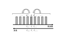
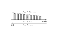
- FIG. 8A is a conceptual diagram of power transition between channels.
- the first horizontal axis indicates frequency, and the second horizontal axis indicates wavelength.
- the channel value (channel i) is smaller on the right side of the horizontal axis and larger on the left side.
- the channel adjacent to channel i on the high-frequency short-wavelength side (right) is channel i-1.
- the channel adjacent to channel i on the low-frequency long-wavelength side (left) is channel i+1.
- the wavelength value corresponding to the channel is smaller on the right side of the horizontal axis and larger on the left side ( ⁇ i+1 > ⁇ i > ⁇ i-1 ).
- the frequency value is larger on the right side of the horizontal axis and smaller on the left side (f i+1 ⁇ f i ⁇ f i-1 ).
- the optical signal of each channel is transmitted through the optical fiber over a predetermined span length.
- the power P i-1 of the channel adjacent to channel i on the higher frequency/shorter wavelength side (right) transitions to the power P i of channel i.
- the power P i of channel i transitions to the power P i+1 of the channel adjacent to channel i on the lower frequency/longer wavelength side (left).
- the signal quality of the post-transmission power of each channel varies depending on the wavelength.
- the post-transmission power P i-1 , etc. of a channel adjacent to channel i on the higher frequency/shorter wavelength side (right) has a larger loss as the frequency increases.
- the post-transmission power P i+1 , etc. of a channel adjacent to channel i on the lower frequency/longer wavelength side (left) has a smaller loss as the frequency decreases. Therefore, as shown by the two-dot chain line in Fig. 8B, the spectrum of the post-transmission power of each channel has a downward slope (tilt) to the right.
- Hiroki Kawahara, Kohei Saito, Sachio Suda, Takeshi Seki, and Hideki Maeda “Cancellation of Static and Dynamic Power Transitions induced by inter-band Stimulated Raman Scattering in C+L-band WDM Transmission,” 25th OptoElectronics and Communications Conference, Taipei, Taiwan, Oct. 2020.
- Fukutaro Hamaoka Kyo Minoguchi, Takeo Sasai, Asuka Matsushita, Masanori Nakamura, Seiji Okamoto, Etsushi Yamazaki, and Yoshiaki Kisaka, “150.3-Tb/s Ultra-Wideband (S, C, and L Bands) Single-Mode Fiber Transmission over 40 -km Using >519Gb/s/ ⁇ PDM-128QAM Signals,” 44th European Conference on Optical Communication, Rome, Italy, Sept. 2018.
- DWDM Dense Wavelength Division Multiplexing
- C-band Conventional band
- L-band Long wavelength band
- the wavelength and frequency of the C-band are (1530-1565 nm, 191.56-195.94 THz).
- the wavelength and frequency of the L-band are (1565-1625 nm, 184.49-191.56 THz). Therefore, the wavelength band of the C-band or L-band is approximately 4.8 THz wide.
- the present invention aims to solve the above problems and calculate the input power that eliminates the gradient of signal quality during transmission or the gradient of incoming power in ultra-wideband DWDM of 15 THz or more.
- the calculation device is a calculation device that calculates the input power of each channel in a band having a width of 15 THz or more to an optical fiber transmission line, and is characterized in that the transition of power in the transmission line due to the influence of stimulated Raman scattering depends on the number of existing channels in the optical fiber transmission line, and the input power is calculated using a coefficient that indicates the slope of the input power spectrum.
- the present invention it is possible to calculate the input power that eliminates the gradient of the signal quality during transmission or the gradient of the incoming power in ultra-wideband DWDM of 15 THz or more.
- FIG. 1 is a schematic configuration diagram of a system including a computing device according to an embodiment.
- FIG. 1 is a schematic diagram of a wavelength multiplexing network.
- FIG. 1 is a schematic diagram of a power spectrum.
- 4 is a flowchart showing a flow of processing of the computing device according to the first embodiment.
- 10 is a flowchart showing a process flow of a computing device according to a second embodiment.
- 13 is a flowchart showing a process flow of a computing device according to a third embodiment.
- 13 is a flowchart showing a process flow of a computing device according to a fourth embodiment.
- 11 is a graph showing signal quality according to an example and a comparative example.
- 11 is a graph showing incoming power according to an embodiment and a comparative example.
- FIG. 2 is a hardware configuration diagram illustrating an example of a computer that realizes the functions of a computing device according to an embodiment.
- FIG. 2 is a conceptual diagram of power transition between channels.
- the optical transmission system 1 includes a network facility monitoring device 10 and a network device 20 .
- the network equipment monitoring device 10 is configured, for example, by a network element operation system (NE-OpS).
- the network equipment monitoring device 10 includes a control unit 11 that monitors the network devices 20.
- the network device 20 is, for example, an optical transmission device such as a ROADM (Reconfigurable Optical Add/Drop Multiplexer).
- the network device 20 includes, for example, a transponder 21, a wavelength selective switch (WSS) 22, an optical amplifier unit 23, and a control unit 24.
- WSS wavelength selective switch
- the number of network devices 20 is arbitrary. When distinguishing between the three network devices shown in FIG. 1, they are written as NE1, NE2, and NE3, and when not distinguishing between them, they are written as network device 20.
- an electrical signal is input from an external communication device to the transponder 21 of the network device NE1
- this electrical signal is converted to an optical signal by the transponder 21, multiplexed by the wavelength selective switch 22, amplified by the optical amplifier 23, and then transmitted to the outside.
- This optical signal is amplified, for example, by the optical amplifier 23 of the network device NE3.
- This amplified optical signal is amplified, for example, by the optical amplifier 23 of the network device NE2, then demultiplexed by the wavelength selective switch 22, received by the transponder 21, and transmitted to a communication device (not shown).
- this optical transmission system 1 is for bidirectional communication.
- the network device NE3 is a device specialized in amplifying optical signals.
- optical fiber transmission lines F1 to F11 are laid between multiple buildings B1 to B6, forming a wavelength multiplexing network.
- At least one network device 20 is installed in each of the buildings B1 to B6.
- the network device 20 includes a calculation device 30.
- the control units 24 of the NE1 and NE2, which are optical transmission devices such as ROADMs, include the calculation device 30 (see FIG. 1).
- the calculation device 30 calculates the input power of each channel in a band having a width of 15 THz or more to an optical fiber transmission line.
- the calculation device 30 assumes that the transition of the power in the transmission line due to the influence of stimulated Raman scattering depends on the number of existing channels in the optical fiber transmission line, and calculates the input power using a coefficient indicating the slope of the input power spectrum.
- the calculation device 30 does not require optimization by iterative calculation.
- the calculation device 30 executes calculation of the input power of each channel based on the relational expression of the transmission line fiber input power.
- the relational expression of the transmission line fiber input power relates the transmission line fiber input power ratio of adjacent channels as a coefficient indicating the slope of the input power spectrum.
- the relational expression of the transmission line fiber input power is based on OSNR, which is a signal quality parameter expressed assuming that the loss coefficient of the transmission line fiber and the noise figure of the amplifier are uniform with respect to frequency.
- This relational expression of the transmission line fiber input power can make the incoming power for each span uniform in the high-frequency side channel.
- the high-frequency side channel means a group of channels that are placed in the high-frequency band when a multi-band frequency band having a width of 15 THz or more is divided into two.
- OSNR is an abbreviation for Optical Signal to Noise Ratio.
- the calculation device 30 can calculate the input power of each channel based on the following formula (2), with the signal quality parameter being the OSNR expressed by the following formula (1):
- OSNR i OSNR of channel i
- P i transmission fiber input power of channel i [W]
- LOSS i span loss of channel i (including the effect of stimulated Raman scattering)
- F noise figure of the amplifier
- N number of spans
- h Planck's constant [mJ s]
- f i frequency of channel i [THz]
- f r frequency of noise bandwidth [THz]
- ⁇ loss coefficient of the transmission fiber [km -1 ]
- r coefficient indicating the slope of the input power spectrum, which is the ratio of the transmission fiber input power of adjacent channels
- k slope of the Raman gain coefficient [km -1 W -1 THz -1 ]
- f channel spacing [THz]
- L span length [km]
- ⁇ 1 utilization rate of band 1
- ⁇ 2 utilization rate of band 2
- ⁇ 3 utilization rate of band 3
- m is the channel number determined by the Raman gain
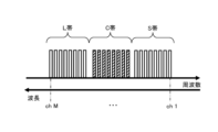
- a multi-band with a width of 15 THz or more is composed of the L band, C band, and S band (Short-wavelength band), as shown in Figure 2B.
- Channel 1 (ch 1) is set to the S band
- channel M (ch M) is set to the L band.
- band 1 is the S band
- band 2 is the C band
- band 3 is the L band.
- the wavelength, frequency of the S band is (1460-1530 nm, 195.94-205.34 THz).
- Multi-bands can also be configured with the U band (ultralong wavelength band), L band, and C band.
- band 1 is the C band
- band 2 is the L band
- band 3 is the U band.
- the wavelength and frequency of the U band are (1625-1675 nm, 178.97-184.49 THz).
- Multi-bands can also be configured with U, L, C, and S bands.
- band 1 is the S band
- band 2 is the C band
- band 3 is the L band
- band 4 is the U band.
- the multi-band may include the E-band (Extended-band) with wavelengths of 1360-1460 nm.
- stimulated Raman scattering occurs in which light of 1530 nm (195.9 THz) is amplified for incident light of 1430 nm (209.6 THz), and the calculation device 30 can calculate the input power for stabilizing the quality and power of the received signal.
- the type of the optical fiber transmission line is not particularly limited.
- the type of the optical fiber transmission line may be, for example, G.652 SMF (single mode optical fiber), G.653 DSF (Dispersion-shifted fiber), or G.654 CSF (Cut-off shifted fiber).
- the span length is not particularly limited. The span length may be, for example, 0-1000 km.
- the optical transmission system 1 can use, for example, optical fiber for undersea systems or optical fiber for terrestrial systems.
- the optical transmission system 1 is configured to accommodate fluctuations in the number of existing channels in the optical fiber transmission path, which is particularly required for terrestrial systems.
- the channel arrangement within each band is not important. Flexible grids are accommodated by replacing channels with grids.
- the input power of the optical fiber transmission line is adjusted by one or all of the amplifiers, attenuators, and wavelength selective switches, for example, by control from the network equipment monitoring device 10 via an interface.
- the amplifiers, attenuators, and wavelength selective switches can be devices that support multiple bands, or devices that support a single band. When multiple bands need to be multiplexed or demultiplexed, this is done by either or both of a coupler and a wavelength selective switch.
- the input power of the optical fiber transmission line can also be adjusted by one or all of the amplifiers, attenuators, and wavelength selective switches, by control from an EMS (Element Management System) (not shown) via an interface.
- EMS lement Management System
- the network device 20 may be, for example, a transmission device having any or all of the functions of add, drop, and cross connect.
- the control units 24 of the network devices NE1 and NE2 are described as being equipped with the computing device 30, this is not limiting.
- the control unit 24 of the network device NE3 may also be equipped with the computing device 30.
- the control unit 11 of the network equipment monitoring device 10 and an EMS may also be equipped with the computing device 30.
- the first and second embodiments are described as configurations in which the input power to the optical fiber transmission path is calculated in the optical transmission system 1 in order to eliminate the gradient in the signal quality.
- the third and fourth embodiments are described as configurations in which the input power to the optical fiber transmission path is calculated in the optical transmission system 1 in order to eliminate the gradient in the span incoming power.
- the calculation device 30 is a device intended to eliminate the gradient of signal quality.
- the calculation device 30 searches for and determines a coefficient indicating the gradient of the input power spectrum based on the GSNR when the incoming OSNR is uniform, under the condition that the GSNR of the highest frequency channel is maximum when the incoming OSNR is uniform and the highest frequency channel has the highest input power among all channels.
- the calculation device 30 calculates the transmission line fiber input power for all channels using the determined coefficient.
- GSNR is an abbreviation for Generalized signal-to-noise ratio.
- the calculation device 30 uses, for example, the following formula (3) as the GSNR when the incoming OSNR is uniform.
- the highest frequency channel is assumed to be channel 1.
- the coefficient indicating the gradient of the input power spectrum is assumed to be the transmission line fiber input power ratio r.
- GSNR i GSNR of channel i
- P ASE,i linear noise power of channel i [W]
- P NLI,i nonlinear noise power of channel i [W]
- h Planck's constant [J s]
- ⁇ 0,i loss coefficient of channel i just after input to the transmission fiber [km -1 ]
- ⁇ i loss coefficient of channel i averaged along the length of the transmission fiber [km -1 ]
- ⁇ i nonlinear noise coefficient of channel i [W -2 ]
- ⁇ nonlinear coefficient [km -1 W -1 ]
- ⁇ 2 group velocity dispersion [ps 2 km -1 ].
- the unit prefix p indicates 10 -12 .
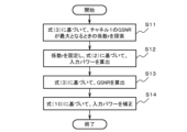
- the calculation device 30 first searches for the coefficient r at which the GSNR of channel 1 is maximized based on formula (3) (step S11). Then, the calculation device 30 fixes the coefficient r and calculates the input power based on formula (2) (step S12). Note that the calculation device 30 according to the first embodiment can also calculate the GSNR for all channels based on formula (3) using the input power calculated for all channels.
- the calculation device 30 according to the second embodiment is a device intended to eliminate the gradient of signal quality.
- the calculation device 30 according to the second embodiment adjusts the input power calculated by the calculation device 30 according to the first embodiment to calculate a corrected input power.
- the calculation device 30 according to the second embodiment uses, for calculation, the transmission line fiber input power for all channels calculated based on the coefficient determined by searching and the relational expression of the transmission line fiber input power, and the GSNR for all channels when the incoming OSNR is uniform.
- the calculation device 30 fixes the optical fiber transmission line input power of the highest frequency channel, and calculates the corrected input power by adjusting the optical fiber transmission line input power of each channel so as to cancel the GSNR difference between the channels.
- the calculation device 30 calculates a corrected input power by substituting r determined by the calculation device 30 according to the first embodiment, the transmission line fiber input power P i for all channels calculated based on the formula (2), and the GSNR i for all channels calculated based on the formula (3) into the right side of the following formula (10).
- the accent of P is a hat.
- Hat P i is the input power after P i is corrected.
- lnr indicates the natural logarithm of r.
- the calculation device 30 calculates the GSNR based on the formula (3) (step S13). Then, the calculation device 30 corrects the input power based on the formula (10) (step S14). The calculation device 30 can calculate the input power that eliminates the gradient of the signal quality by considering the change in the amount of stimulated Raman scattering generation by using the formula (10). Note that the calculation device 30 can also calculate the GSNR for all channels based on the formula (3) by using the input power corrected for all channels.
- the calculation device 30 according to the third embodiment is a device intended to eliminate the inclination of the span incoming power.
- the calculation device 30 according to the third embodiment determines a coefficient indicating the inclination of the input power spectrum to an arbitrary value, and calculates the transmission line fiber input power for all channels based on a relational expression of the transmission line fiber input power. For example, the calculation device 30 determines a transmission line fiber input power ratio r to an arbitrary value, and calculates the transmission line fiber input power P i for all channels based on the formula (2).
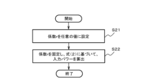
- the calculation device 30 As shown in FIG. 4A, the calculation device 30 according to the third embodiment first sets the coefficient r to an arbitrary value (step S21). Then, the calculation device 30 fixes the coefficient r and calculates the input power based on the formula (2) (step S22).
- the calculation device 30 according to the fourth embodiment is a device intended to eliminate the inclination of the span incoming power.
- the calculation device 30 according to the fourth embodiment adjusts the input power calculated by the calculation device 30 according to the third embodiment to calculate a corrected input power.
- the calculation device 30 according to the fourth embodiment uses a coefficient determined by searching and the transmission line fiber input power for all channels calculated based on a relational expression of the transmission line fiber input power for calculation.
- the calculation device 30 fixes the optical fiber transmission line input power of the highest frequency channel, and calculates the corrected input power by adjusting the optical fiber transmission line input power of each channel so as to cancel the incoming power difference between the channels.
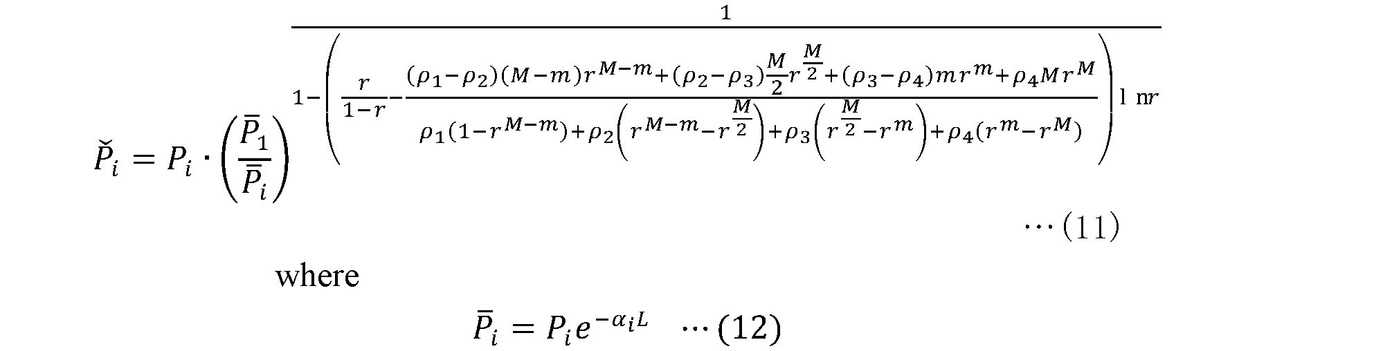
- the calculation device 30 according to the fourth embodiment calculates a corrected input power by substituting r determined by the calculation device 30 according to the third embodiment and the transmission line fiber input power P i for all channels calculated based on the formula (2) into the right side of the following formula (11).
- the accent of P on the left side of formula (11) is a Ha ⁇ ek number.
- Ha ⁇ ek P i is the input power with P i corrected.
- the accent of P on the left side of formula (12) is an overline.
- the overline P i is defined by formula (12).
- ⁇ represents the loss coefficient [km -1 ] of the transmission fiber
- L represents the span length [km].
- the calculation device 30 corrects the input power based on formula (11) (step S23).
- the calculation device 30 can calculate the input power that eliminates the gradient of the incoming power, taking into account the change in the amount of stimulated Raman scattering generated.
- the first simulation is a verification experiment of the effect of eliminating the gradient of the signal quality by the computing device 30 according to the first embodiment.
- the maximum number of channels M is set to 400. Note that the maximum number of channels M is the maximum value of the number of channels that can be set.
- the calculation device 30 of the first embodiment calculated the transmission fiber input power P i for all channels under the condition that the GSNR 1 of channel 1 is maximum based on the formula (3).
- the transmission fiber input power P i is a power obtained by raising the input power of the short wavelength band in advance and has a slope.
- the GSNR i was calculated again for all channels based on the formula (3) using this P i . This result was set as Example 1.
- the result of calculating the GSNR when the input power is flat was set as Comparative Example 1.
- Example 5 is a graph showing the results of the first simulation.
- the horizontal axis of the graph indicates frequency, and the vertical axis indicates GSNR.
- the thin line indicates Example 1
- the dashed line indicates Comparative Example 1.
- the GSNR is 19.7 dB at channel number 400 (180.50 THz), and the GSNR is 8.94 dB at channel number 1 (205.00 THz).
- the GSNR is 13.4 dB in channel number 400 (180.50 THz)
- the GSNR is 14.4 dB in channel number 1 (205.00 THz).
- Example 1 shows good results in that the variation in signal quality due to wavelength can be improved.
- the GSNR obtained by full search optimization of the offset-tilt method was calculated. This result is designated as Comparative Example 2.
- the dashed two-dot line indicates Comparative Example 2.
- a gradient in signal quality occurred from 200 to 205 THz.
- the GSNR (14.4 dB) of channel number 1 in Example 1 is smaller than the GSNR (14.7 dB) of channel number 1 obtained in Comparative Example 2. This suggests that there is room for improving signal quality by relaxing the condition of uniform incoming OSNR in Example 1.
- the calculation device 30 of the second embodiment in which the condition of uniform incoming OSNR is relaxed, is expected to further improve signal quality.
- the second simulation is a verification experiment of the effect of eliminating the gradient of the signal quality by the calculation device 30 according to the second embodiment.
- the simulation conditions are the same as those of the first simulation.
- the calculation device 30 according to the second embodiment adjusts the input power calculated by the calculation device 30 according to the first embodiment based on the formula (10) to calculate the corrected input power.
- the GSNR i is calculated again for all channels based on the formula (3) using the corrected input power. This result is set as Example 2.
- Figure 5 also shows the results of the second simulation.
- the thick line indicates Example 2.
- the GSNR is 15.0 dB
- the GSNR is 14.6 dB.
- Example 2 shows good results in that the gradient in signal quality is eliminated and the variation in signal quality due to wavelength can be improved.
- the spectrum of signal quality has become flatter.
- the third simulation is a verification experiment of the effect of eliminating the gradient of the span incoming power by the calculation device 30 according to the third embodiment.
- the simulation conditions are the same as those of the first simulation.
- the calculation device 30 according to the third embodiment determines r to be an arbitrary value, and calculates the transmission line fiber input power P i for all channels based on the formula (2).
- the transmission line fiber input power P i is a power obtained by raising the input power of the short wavelength band in advance and has a gradient.
- the incoming power was calculated using this input power P i .
- This result was set as Example 3.
- the result of calculating the incoming power when the input power is flat was set as Comparative Example 3.
- the calculation method of the incoming power can be a known method described in, for example, Non-Patent Document 1.
- Figure 6 is a graph showing the results of the third simulation.
- the horizontal axis of the graph indicates frequency, and the vertical axis indicates incoming power.
- the thin line indicates Example 3, and the dashed line indicates Comparative Example 3.
- the incoming power is -10.998 dBm, and at channel number 1 (205.00 THz), the incoming power is -27.162 dBm.
- the incoming power is -23.312 dBm, and at channel number 1 (205.00 THz), the incoming power is -21.010 dBm.
- FIG 6 in Comparative Example 3, since no special measures were taken, a gradient in the incoming power occurred. In Example 3, the gradient in the incoming power was clearly eliminated.
- the fourth simulation is a verification experiment of the effect of eliminating the gradient of the span incoming power by the calculation device 30 according to the fourth embodiment.
- the simulation conditions are the same as those of the first simulation.
- the calculation device 30 according to the fourth embodiment adjusts the input power calculated by the calculation device 30 according to the third embodiment based on the formula (11) to calculate the corrected input power.
- the incoming power is calculated using this corrected input power. This result is set as Example 4.
- Figure 6 also shows the results of the fourth simulation.
- the thick line indicates Example 4.
- Example 4 for example, at channel number 400 (180.50 THz), the incoming power is -20.029 dBm, and at channel number 1 (205.00 THz), the incoming power is -21.394 dBm.
- Example 4 eliminated the inclination of the incoming power, as in Example 3.
- the incoming power spectrum became flatter.
- the computing device 30 according to each embodiment is realized by a computer 900 having a configuration as shown in Fig. 7.
- Fig. 7 is a hardware configuration diagram showing an example of the computer 900 that realizes the functions of the computing device 30 according to this embodiment.
- the computer 900 has a CPU (Central Processing Unit) 901, a ROM (Read Only Memory) 902, a RAM (Random Access Memory) 903, a HDD (Hard Disk Drive) 904, an input/output I/F (Interface) 905, a communication I/F 906, and a media I/F 907.
- CPU Central Processing Unit
- ROM Read Only Memory
- RAM Random Access Memory
- HDD Hard Disk Drive
- I/F Interface
- the CPU 901 operates based on programs stored in the ROM 902 or the HDD 904.
- the ROM 902 stores a boot program executed by the CPU 901 when the computer 900 starts up, programs related to the hardware of the computer 900, and the like.
- the CPU 901 controls an input device 910 such as a mouse or keyboard, and an output device 911 such as a display or printer, via an input/output I/F 905.
- the CPU 901 acquires data from the input device 910 via the input/output I/F 905, and outputs generated data to the output device 911.
- a GPU Graphics Processing Unit
- a processor may be used as a processor in addition to the CPU 901.
- the HDD 904 stores the programs executed by the CPU 901 and the data used by the programs.
- the communication I/F 906 receives data from other devices via the communication network 920 and outputs the data to the CPU 901, and also transmits data generated by the CPU 901 to other devices via the communication network 920.
- the media I/F 907 reads the program or data stored in the recording medium 912 and outputs it to the CPU 901 via the RAM 903.
- the CPU 901 loads the program related to the target processing from the recording medium 912 onto the RAM 903 via the media I/F 907, and executes the loaded program.
- the recording medium 912 is an optical recording medium such as a DVD (Digital Versatile Disc) or a PD (Phase change rewritable Disk), a magneto-optical recording medium such as an MO (Magneto Optical disk), a magnetic recording medium, or a semiconductor memory, etc.
- the CPU 901 realizes the functions of the computing device 30 by executing a program loaded onto the RAM 903.
- the HDD 904 stores data in the RAM 903.
- the CPU 901 reads and executes a program related to the target processing from the recording medium 912.
- the CPU 901 can also read a program related to the target processing from another device via the communication network 920.
- the calculation device 30 calculates the input power of each channel in a band having a width of 15 THz or more to an optical fiber transmission line, and is characterized in that the transition of power in the transmission line due to the influence of stimulated Raman scattering depends on the number of existing channels in the optical fiber transmission line, and the input power is calculated using a coefficient r that indicates the slope of the input power spectrum.
- the calculation device 30 calculates the input power of each channel in a band having a width of 15 THz or more. Therefore, the calculation device 30 can calculate how much the input power of the short wavelength band should be boosted in advance, optimally, to keep the signal quality and incoming power constant from the short wavelength band to the long wavelength band on the receiving side.
- the calculation device 30 is characterized in that it performs calculations of the input power of each channel based on a relational equation for the transmission line fiber input power that makes the incoming power for each span uniform in the high-frequency channel based on the OSNR, which is a signal quality parameter expressed by assuming that the loss coefficient of the transmission line fiber and the noise figure of the amplifier are uniform with respect to frequency, and that relates the transmission line fiber input power ratio of adjacent channels as a coefficient indicating the slope of the input power spectrum.
- the calculation device 30 calculates the input power of each channel in a band having a width of 15 THz or more based on the relational equation for the transmission line fiber input power.
- the relational equation for the transmission line fiber input power relates the transmission line fiber input power ratio of adjacent channels as a coefficient indicating the slope of the input power spectrum, and since the incoming power for each span is made uniform in the high-frequency side channels, the incoming OSNR of the high-frequency side channels can be made uniform.
- the calculation device 30 can calculate the input power that eliminates the slope of the signal quality in DWDM and the input power that eliminates the slope of the span incoming power.
- the calculation device 30 is characterized in that it searches for and determines coefficients based on the GSNR when the incoming OSNR is uniform, under the condition that the GSNR of the highest frequency channel is maximum when the incoming OSNR is uniform and the highest frequency channel has the highest input power among all channels, and uses the determined coefficients to calculate the transmission path fiber input power for all channels.
- the calculation device 30 searches for coefficients under the condition that the GSNR of the highest frequency channel is maximized at this time, thereby maximizing the signal quality after uniformizing it. In other words, the calculation device 30 maximizes the signal quality of the channel with the lowest signal quality.
- the input power determined at this time and calculated based on the relational expression using the coefficients becomes the input power that eliminates the gradient of the signal quality. Therefore, the calculated input power can flatten the signal quality that normally has a gradient such that the GSNR of the channel increases as the frequency decreases.
- the calculation device 30 is characterized by determining the coefficients to arbitrary values and calculating the transmission fiber input power for all channels based on the relational equation.
- the calculation device 30 calculates the input power based on the relational expression using an arbitrary coefficient.
- the coefficient is the transmission fiber input power ratio of adjacent channels, and corresponds to the common ratio of the geometric progression. Therefore, according to the calculated input power, it is possible to flatten the incoming power, which normally has a slope such that the lower the frequency, the greater the incoming power of the channel. Therefore, the calculation device 30 can calculate the input power that eliminates the slope of the span incoming power.
- the calculation device 30 is characterized in that it uses the determined coefficients, the transmission line fiber input power for all channels calculated based on the relational expression, and the GSNR for all channels when the incoming OSNR is uniform to fix the optical fiber transmission line input power of the highest frequency channel and calculate the corrected input power by adjusting the optical fiber transmission line input power of each channel so as to cancel out the GSNR difference between the channels.
- the calculation device 30 fixes the optical fiber transmission line input power of the highest frequency channel, and adjusts the optical fiber transmission line input power of each channel so as to cancel out the GSNR difference between the channels.
- the calculation device 30 can increase the input power of a channel with insufficient GSNR, while decreasing the input power of a channel with excessive GSNR. Therefore, the calculation device 30 can maximize the signal quality while equalizing it.
- the calculation device 30 uses the determined coefficient and the transmission line fiber input power for all channels calculated based on the relational expression to fix the optical fiber transmission line input power of the highest frequency channel and calculate the corrected input power by adjusting the optical fiber transmission line input power of each channel so as to cancel out the incoming power difference between the channels.
- the computing device 30 fixes the optical fiber transmission line input power of the highest frequency channel, and adjusts the optical fiber transmission line input power of each channel so as to cancel out the difference in incoming power between channels.
- the computing device 30 can increase the input power of a channel with a shortage of incoming power, and decrease the input power of a channel with an excess of incoming power. As a result, the computing device 30 can equalize the incoming power.
- the calculation method is a calculation method of a calculation device 30 that calculates the input power to an optical fiber transmission line for each channel in a band having a width of 15 THz or more, and is characterized in that the calculation device 30 assumes that the transition of power in the transmission line due to the influence of stimulated Raman scattering depends on the number of existing channels in the optical fiber transmission line, and calculates the input power using a coefficient that indicates the slope of the input power spectrum.
- the calculation device 30 calculates the input power of each channel in a band having a width of 15 THz or more. Therefore, the calculation device 30 can calculate how much the input power of the short wavelength band should be boosted in advance, optimally, to keep the signal quality and incoming power constant from the short wavelength band to the long wavelength band on the receiving side.
Landscapes
- Engineering & Computer Science (AREA)
- Computer Networks & Wireless Communication (AREA)
- Signal Processing (AREA)
- Physics & Mathematics (AREA)
- Electromagnetism (AREA)
- Optical Communication System (AREA)
Abstract
Description
図8Aは、チャネル間のパワー遷移の概念図である。第1の横軸は周波数を示し、第2の横軸は波長を示す。ここでは、各チャネルの入力パワーが等しいものとする。チャネルの値(チャネルi)は、横軸において右側が小さく左側が大きい。チャネルiから見て高周波数短波長側(右)に隣接するチャネルはチャネルi-1である。チャネルiから見て低周波数長波長側(左)に隣接するチャネルはチャネルi+1である。なお、チャネルに対応する波長の値は、横軸において右側が小さく左側が大きい(λi+1 > λi > λi-1 )。一方、周波数の値は、横軸において右側が大きく左側が小さい(fi+1< fi < fi-1 )。
[システム構成の概要]
図1に示すように、光伝送システム1は、ネットワーク設備監視装置10と、ネットワーク装置20と、を備えている。
ネットワーク設備監視装置10は、例えば、NE-OpS(Network element operation system)で構成される。ネットワーク設備監視装置10は、ネットワーク装置20を監視する制御部11を備えている。
計算装置30は、15 THz 以上の幅を有するバンドにおける各チャネルの光ファイバ伝送路への入力パワーを計算する。計算装置30は、誘導ラマン散乱の影響による伝送路中パワーの遷移を光ファイバ伝送路内既存チャネル数に依存するものとし、入力パワースペクトルの傾きを示す係数を用いて、入力パワーを計算する。計算装置30は、反復計算による最適化を必要としない。

また、マルチバンドは、U帯とL帯とC帯とS帯で構成することもできる。この例では、高周波側から順番に、バンド 1はS帯であり、バンド 2はC帯であり、バンド 3はL帯であり、バンド 4はU帯である。
さらに、マルチバンドは、波長1360-1460nmのE帯(Extended-band)を含むこともできる。例えば1430nm(209.6THz)の入射光に対して、1530nm(195.9THz)の光が増幅される誘導ラマン散乱が発生するが、計算装置30は、受信信号の品質やパワーを安定させるための入力パワーを計算することができる。
ネットワーク装置NE1,NE2の制御部24が、計算装置30を備えていることとしたが、これに限らない。例えばネットワーク装置NE3の制御部24が、計算装置30を備えることもできる。また、ネットワーク設備監視装置10の制御部11や図示しないEMSが、計算装置30を備えることもできる。
第1実施形態に係る計算装置30は、信号品質の傾斜を解消することを目的とした装置である。計算装置30は、着信 OSNR が均一のときのGSNRに基づいて、着信 OSNR が均一かつ最高周波数チャネルが全チャネル中の最高入力パワーであるときに最高周波数チャネルのGSNRが最大値となる条件で、入力パワースペクトルの傾きを示す係数を探索し、決定する。計算装置30は、決定した係数を用いて、伝送路ファイバ入力パワーを全チャネルについて算出する。なお、GSNRは、Generalized signal-to-noise ratioの略である。計算装置30は、着信 OSNR が均一のときのGSNRとして、たとえば、次の数式(3)を用いる。ここで、最高周波数チャネルは、チャネル 1であるものとする。入力パワースペクトルの傾きを示す係数は、伝送路ファイバ入力パワー比rであるものとする。

第2実施形態に係る計算装置30は、信号品質の傾斜を解消することを目的とした装置である。第2実施形態に係る計算装置30は、第1実施形態に係る計算装置30で算出した入力パワーを調整して、補正された入力パワーを算出する。第2実施形態に係る計算装置30は、探索して決定した係数と、伝送路ファイバ入力パワーの関係式に基づいて算出した全チャネルについての伝送路ファイバ入力パワーと、着信 OSNR が均一のときの全チャネルについてのGSNRと、を計算に用いる。計算装置30は、最高周波数チャネルの光ファイバ伝送路入力パワーを固定し、チャネル間の GSNR差を打ち消すように各チャネルの光ファイバ伝送路入力パワーを調整することで、補正された入力パワーを算出する。

計算装置30は、数式(10)を用いることで、誘導ラマン散乱発生量の変化を考慮して、信号品質の傾斜を解消する入力パワーを算出することができる。なお、計算装置30は、全チャネルについて補正した入力パワーを用いて、数式(3)に基づいて、全チャネルについてのGSNRを算出することもできる。
第3実施形態に係る計算装置30は、スパン着信パワーの傾斜を解消することを目的とした装置である。第3実施形態に係る計算装置30は、入力パワースペクトルの傾きを示す係数を任意の値に決定し、伝送路ファイバ入力パワーの関係式に基づいて、伝送路ファイバ入力パワーを全チャネルについて算出する。計算装置30は、たとえば、伝送路ファイバ入力パワー比 r を任意の値に決定し、数式(2)に基づいて、伝送路ファイバ入力パワー Piを全チャネルについて算出する。
第4実施形態に係る計算装置30は、スパン着信パワーの傾斜を解消することを目的とした装置である。第4実施形態に係る計算装置30は、第3実施形態に係る計算装置30で算出した入力パワーを調整して、補正された入力パワーを算出する。第4実施形態に係る計算装置30は、探索して決定した係数と、伝送路ファイバ入力パワーの関係式に基づいて算出した全チャネルについての伝送路ファイバ入力パワーと、を計算に用いる。計算装置30は、最高周波数チャネルの光ファイバ伝送路入力パワーを固定し、チャネル間の着信パワー差を打ち消すように各チャネルの光ファイバ伝送路入力パワーを調整することで、補正された入力パワーを算出する。
(第1シミュレーション)
第1シミュレーションは、第1実施形態に係る計算装置30による信号品質の傾斜を解消する効果の検証実験である。シミュレーション条件としては、最大チャネル数Mを400とした。なお、最大チャネル数Mは、設定されるチャネル数の最大値である。
S帯の195.95~205.00 THzにおいて、中心周波数間隔f=50[GHz]で、チャネル数182(チャネル番号1~182)の周波数fiを設定した。
C帯の191.60~195.90 THzにおいて、中心周波数間隔f=50[GHz]で、チャネル数87(チャネル番号183~269)の周波数fiを設定した。
L帯の185.05~191.55 THzにおいて、中心周波数間隔f=50[GHz]で、チャネル数131(チャネル番号270~400)の周波数fiを設定した。
比較例1では、例えばチャネル番号400(180.50 THz)において、GSNRは、19.7 dBであり、チャネル番号1(205.00 THz)において、GSNRは、 8.94 dBである。
実施例1では、例えばチャネル番号400(180.50 THz)において、GSNRは、13.4 dBであり、チャネル番号1(205.00 THz)において、GSNRは、14.4 dBである。
図5に示すように、比較例1では、なんら工夫をしていないので、信号品質の傾斜が発生した。実施例1では、明らかに信号品質の傾斜が解消された。実施例1は、波長による信号品質のばらつきを改善できる良好な結果を示している。
第2シミュレーションは、第2実施形態に係る計算装置30による信号品質の傾斜を解消する効果の検証実験である。シミュレーション条件は、第1シミュレーションの条件と同様である。第2実施形態の計算装置30は、第1実施形態に係る計算装置30で算出した入力パワーを、数式(10)に基づいて調整し、補正された入力パワーを算出した。次に、検証のために、この補正された入力パワーを用いて、あらためて数式(3)に基づいて、GSNRiを全チャネルについて算出した。この結果を実施例2とした。
第3シミュレーションは、第3実施形態に係る計算装置30によるスパン着信パワーの傾斜を解消する効果の検証実験である。シミュレーション条件は、第1シミュレーションの条件と同様である。第3実施形態の計算装置30は、r を任意の値に決定し、数式(2)に基づいて、伝送路ファイバ入力パワー Piを全チャネルについて算出した。なお、伝送路ファイバ入力パワーPiは、短波長帯の入力パワーを予め持ち上げたものであり傾斜がついている。次に、検証のために、この入力パワー Piを用いて着信パワーを算出した。この結果を実施例3とした。一方、入力パワーがフラットな場合について着信パワーを算出した結果を比較例3とした。なお、着信パワー(誘導ラマン散乱によるパワー遷移)の計算方法は、例えば非特許文献1等に記載された公知の手法を用いることができる。
第4シミュレーションは、第4実施形態に係る計算装置30によるスパン着信パワーの傾斜を解消する効果の検証実験である。シミュレーション条件は、第1シミュレーションの条件と同様である。第4実施形態の計算装置30は、第3実施形態に係る計算装置30で算出した入力パワーを、数式(11)に基づいて調整し、補正された入力パワーを算出した。次に、検証のために、この補正された入力パワーを用いて着信パワーを算出した。この結果を実施例4とした。
各実施形態に係る計算装置30は、例えば図7に示すような構成のコンピュータ900によって実現される。図7は、本実施形態に係る計算装置30の機能を実現するコンピュータ900の一例を示すハードウェア構成図である。コンピュータ900は、CPU(Central Processing Unit)901、ROM(Read Only Memory)902、RAM(Random Access Memory)903、HDD(Hard Disk Drive)904、入出力I/F(Interface)905、通信I/F906およびメディアI/F907を有する。
以上説明したように、計算装置は、15 THz 以上の幅を有するバンドにおける各チャネルの光ファイバ伝送路への入力パワーを計算する計算装置30であって、誘導ラマン散乱の影響による伝送路中パワーの遷移を光ファイバ伝送路内既存チャネル数に依存するものとし、入力パワースペクトルの傾きを示す係数rを用いて、入力パワーを計算することを特徴とする。
10 ネットワーク設備監視装置(NE-OpS)
11 制御部
20 ネットワーク装置(NE)
21 トランスポンダ
22 波長選択スイッチ(WSS)
23 光増幅部
24 制御部
30 計算装置
Claims (8)
誘導ラマン散乱の影響による伝送路中パワーの遷移を光ファイバ伝送路内既存チャネル数に依存するものとし、入力パワースペクトルの傾きを示す係数を用いて、入力パワーを計算することを特徴とする計算装置。
前記計算装置は、
誘導ラマン散乱の影響による伝送路中パワーの遷移を光ファイバ伝送路内既存チャネル数に依存するものとし、入力パワースペクトルの傾きを示す係数を用いて、入力パワーを計算することを特徴とする計算方法。
Priority Applications (2)
| Application Number | Priority Date | Filing Date | Title |
|---|---|---|---|
| JP2025501966A JPWO2024176338A1 (ja) | 2023-02-21 | 2023-02-21 | |
| PCT/JP2023/006195 WO2024176338A1 (ja) | 2023-02-21 | 2023-02-21 | 計算装置、計算方法およびプログラム |
Applications Claiming Priority (1)
| Application Number | Priority Date | Filing Date | Title |
|---|---|---|---|
| PCT/JP2023/006195 WO2024176338A1 (ja) | 2023-02-21 | 2023-02-21 | 計算装置、計算方法およびプログラム |
Publications (1)
| Publication Number | Publication Date |
|---|---|
| WO2024176338A1 true WO2024176338A1 (ja) | 2024-08-29 |
Family
ID=92500409
Family Applications (1)
| Application Number | Title | Priority Date | Filing Date |
|---|---|---|---|
| PCT/JP2023/006195 Ceased WO2024176338A1 (ja) | 2023-02-21 | 2023-02-21 | 計算装置、計算方法およびプログラム |
Country Status (2)
| Country | Link |
|---|---|
| JP (1) | JPWO2024176338A1 (ja) |
| WO (1) | WO2024176338A1 (ja) |
Citations (5)
| Publication number | Priority date | Publication date | Assignee | Title |
|---|---|---|---|---|
| JP2002368691A (ja) * | 2001-06-04 | 2002-12-20 | Hitachi Ltd | 波長多重用光伝送装置および波長多重信号の光増幅方法 |
| US6859622B1 (en) * | 2000-12-26 | 2005-02-22 | Nortel Networks Limited | Predictive optimization of wavelength division multiplexed systems |
| JP2008042096A (ja) * | 2006-08-09 | 2008-02-21 | Fujitsu Ltd | 光増幅器および光伝送システム |
| JP2014229913A (ja) * | 2013-05-17 | 2014-12-08 | 株式会社日立製作所 | Wdm信号光中継装置、方法及びシステム |
| WO2019230480A1 (ja) * | 2018-05-31 | 2019-12-05 | 日本電信電話株式会社 | 光伝送制御方法及び光伝送システム |
-
2023
- 2023-02-21 WO PCT/JP2023/006195 patent/WO2024176338A1/ja not_active Ceased
- 2023-02-21 JP JP2025501966A patent/JPWO2024176338A1/ja active Pending
Patent Citations (5)
| Publication number | Priority date | Publication date | Assignee | Title |
|---|---|---|---|---|
| US6859622B1 (en) * | 2000-12-26 | 2005-02-22 | Nortel Networks Limited | Predictive optimization of wavelength division multiplexed systems |
| JP2002368691A (ja) * | 2001-06-04 | 2002-12-20 | Hitachi Ltd | 波長多重用光伝送装置および波長多重信号の光増幅方法 |
| JP2008042096A (ja) * | 2006-08-09 | 2008-02-21 | Fujitsu Ltd | 光増幅器および光伝送システム |
| JP2014229913A (ja) * | 2013-05-17 | 2014-12-08 | 株式会社日立製作所 | Wdm信号光中継装置、方法及びシステム |
| WO2019230480A1 (ja) * | 2018-05-31 | 2019-12-05 | 日本電信電話株式会社 | 光伝送制御方法及び光伝送システム |
Non-Patent Citations (1)
| Title |
|---|
| FUKUTARO HAMAOKA: "Invited Talk] >100-Tb/s Capacity Wideband WDM Optical Transmission Technologie", TECHNICAL REPORT OF THE INSTITUTE OF ELECTRONICS, INFORMATION AND COMMUNICATION ENGINEERS., IEICE, JP, vol. 121, no. OCS-320 - OCS2021-38, 14 January 2022 (2022-01-14), JP, pages 28 - 31, XP009557001 * |
Also Published As
| Publication number | Publication date |
|---|---|
| JPWO2024176338A1 (ja) | 2024-08-29 |
Similar Documents
| Publication | Publication Date | Title |
|---|---|---|
| WO2024176341A1 (ja) | 計算装置、計算方法およびプログラム | |
| EP0668675B1 (en) | Multi-channel optical fiber communication system | |
| US6344914B1 (en) | Gain equalizer which includes a plurality of optical filters for equalizing the gain of an optical amplifier | |
| EP1410535B1 (en) | Method of power control in an optical communication system | |
| EP1025459A1 (en) | Multiple wavelength bidirectional lightwave amplifier | |
| JP5245747B2 (ja) | 光増幅器および光受信モジュール | |
| JPH10173597A (ja) | 光イコライザ | |
| Escobar-Landero et al. | S+ C+ L high-capacity transmission systems: Challenges and opportunities | |
| US5689594A (en) | Multiple wavelength bidirectional lightwave amplifier | |
| WO1997024824A9 (en) | Multiple wavelength bidirectional lightwave amplifier | |
| JP4659498B2 (ja) | 光伝送装置 | |
| WO2024176338A1 (ja) | 計算装置、計算方法およびプログラム | |
| CN1784849B (zh) | 用于对光复用信号进行预加重的方法 | |
| JP3999629B2 (ja) | 波長多重光伝送システムおよびその中継局 | |
| WO2024050740A1 (en) | Systems and methods for improving a performance of a communication link | |
| JP7722585B2 (ja) | 計算装置、ネットワーク装置、計算方法およびプログラム | |
| JP7722584B2 (ja) | 計算装置、計算方法およびプログラム | |
| US20240388363A1 (en) | Spatially distributed optical fibre based transmission link and method thereof | |
| Liu et al. | Multi-stage Programmable Raman Amplifier-based Online Transmission Optimization for Multi-band Dynamic Optical Networks | |
| US7127173B2 (en) | Method of adjusting power for a wavelength-division multiplexed optical transmission system | |
| Saavedra et al. | Capacity increases obtained extending the transmission bandwidth in optical communication systems | |
| Yang et al. | Quality of transmission optimization in a multi-band optical system: a stepwise multi-device joint configuration algorithm | |
| US20250085608A1 (en) | Transmission system, apparatus, transmission method and program | |
| CN1310872A (zh) | 掺铒光纤放大器中有中间级衰减器的增益倾斜控制 | |
| JP2025021316A (ja) | 光伝送装置および送信光パワー制御方法 |
Legal Events
| Date | Code | Title | Description |
|---|---|---|---|
| 121 | Ep: the epo has been informed by wipo that ep was designated in this application |
Ref document number: 23923992 Country of ref document: EP Kind code of ref document: A1 |
|
| ENP | Entry into the national phase |
Ref document number: 2025501966 Country of ref document: JP Kind code of ref document: A |
|
| WWE | Wipo information: entry into national phase |
Ref document number: 2025501966 Country of ref document: JP |
|
| NENP | Non-entry into the national phase |
Ref country code: DE |
|
| 122 | Ep: pct application non-entry in european phase |
Ref document number: 23923992 Country of ref document: EP Kind code of ref document: A1 |