WO2024172092A1 - 空間チャネル間クロストーク測定方法および空間チャネル間クロストーク測定装置 - Google Patents
空間チャネル間クロストーク測定方法および空間チャネル間クロストーク測定装置 Download PDFInfo
- Publication number
- WO2024172092A1 WO2024172092A1 PCT/JP2024/005112 JP2024005112W WO2024172092A1 WO 2024172092 A1 WO2024172092 A1 WO 2024172092A1 JP 2024005112 W JP2024005112 W JP 2024005112W WO 2024172092 A1 WO2024172092 A1 WO 2024172092A1
- Authority
- WO
- WIPO (PCT)
- Prior art keywords
- spatial channel
- optical fiber
- light
- division multiplexing
- space division
- Prior art date
- Legal status (The legal status is an assumption and is not a legal conclusion. Google has not performed a legal analysis and makes no representation as to the accuracy of the status listed.)
- Ceased
Links
Images









Classifications
-
- G—PHYSICS
- G01—MEASURING; TESTING
- G01M—TESTING STATIC OR DYNAMIC BALANCE OF MACHINES OR STRUCTURES; TESTING OF STRUCTURES OR APPARATUS, NOT OTHERWISE PROVIDED FOR
- G01M11/00—Testing of optical apparatus; Testing structures by optical methods not otherwise provided for
- G01M11/30—Testing of optical devices, constituted by fibre optics or optical waveguides
- G01M11/31—Testing of optical devices, constituted by fibre optics or optical waveguides with a light emitter and a light receiver being disposed at the same side of a fibre or waveguide end-face, e.g. reflectometers
-
- G—PHYSICS
- G01—MEASURING; TESTING
- G01M—TESTING STATIC OR DYNAMIC BALANCE OF MACHINES OR STRUCTURES; TESTING OF STRUCTURES OR APPARATUS, NOT OTHERWISE PROVIDED FOR
- G01M11/00—Testing of optical apparatus; Testing structures by optical methods not otherwise provided for
- G01M11/30—Testing of optical devices, constituted by fibre optics or optical waveguides
- G01M11/31—Testing of optical devices, constituted by fibre optics or optical waveguides with a light emitter and a light receiver being disposed at the same side of a fibre or waveguide end-face, e.g. reflectometers
- G01M11/3109—Reflectometers detecting the back-scattered light in the time-domain, e.g. OTDR
-
- G—PHYSICS
- G02—OPTICS
- G02B—OPTICAL ELEMENTS, SYSTEMS OR APPARATUS
- G02B6/00—Light guides; Structural details of arrangements comprising light guides and other optical elements, e.g. couplings
- G02B6/02—Optical fibres with cladding with or without a coating
- G02B6/02042—Multicore optical fibres
-
- H—ELECTRICITY
- H04—ELECTRIC COMMUNICATION TECHNIQUE
- H04B—TRANSMISSION
- H04B10/00—Transmission systems employing electromagnetic waves other than radio-waves, e.g. infrared, visible or ultraviolet light, or employing corpuscular radiation, e.g. quantum communication
- H04B10/07—Arrangements for monitoring or testing transmission systems; Arrangements for fault measurement of transmission systems
- H04B10/071—Arrangements for monitoring or testing transmission systems; Arrangements for fault measurement of transmission systems using a reflected signal, e.g. using optical time domain reflectometers [OTDR]
Definitions
- This disclosure relates to a method and device for measuring spatial channel crosstalk.
- This application claims priority to Japanese Application No. 2023-021827, filed February 15, 2023, and incorporates all of the contents of said Japanese application by reference.
- Patent Document 1 and Non-Patent Document 1 disclose a method for measuring inter-core crosstalk in a multi-core optical fiber.
- inter-core crosstalk is measured by injecting measurement light into a certain core at one end of the multi-core optical fiber and detecting the power of measurement light emitted from that core and another core at the other end of the multi-core optical fiber.
- Non-Patent Document 2 discloses a method for measuring inter-core crosstalk in a multi-core optical fiber using an OTDR (Optical Time Domain Reflectometer) measurement technique.
- OTDR Optical Time Domain Reflectometer
- pulsed light is injected into a certain core at one end of the multi-core optical fiber, and the inter-core crosstalk is measured by detecting the time change in the power of backward Rayleigh scattered light emitted from that core and another core at the one end of the multi-core optical fiber.
- the method for measuring crosstalk between spatial channels includes a first step to a fifth step.
- an optical reflection suppression section for suppressing reflection of the test light is formed or provided on the second input/output surface of the space division multiplexing optical fiber.
- the test light is incident on the first spatial channel at the first input/output surface.
- at least a part of the test light is Rayleigh scattered backward in the space division multiplexing optical fiber.
- a first optical power which is the power of the light emitted from the first spatial channel at the first input/output surface among the at least a part of the light
- a second optical power which is the power of the light emitted from the second spatial channel at the first input/output surface among the at least a part of the light
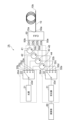
- FIG. 1 is a diagram showing a configuration of a measurement device according to an embodiment of the present disclosure.
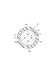
- FIG. 2 is a diagram showing a cross section perpendicular to the central axis of a multi-core optical fiber.
- FIG. 3 is a diagram showing the configuration of a three-port optical coupler (optical circulator).
- FIG. 4 is a diagram showing the configuration of a modified example of the measuring device.
- FIG. 5 is a diagram showing the configuration of another modified example of the measuring device.
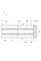
- FIG. 6 is a cross-sectional view showing an example of a light reflection suppressing portion formed or provided on the second incident/exit surface.
- FIG. 7 is a cross-sectional view showing an example of a light reflection suppressing portion formed or provided on the second incident/exit surface.
- FIG. 1 is a diagram showing a configuration of a measurement device according to an embodiment of the present disclosure.
- FIG. 2 is a diagram showing a cross section perpendicular to the central axis of a
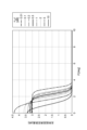
- FIG. 8 is a graph showing the relationship between the crosstalk measurement error caused by the reflected light on the second incident/exit surface and the angle of the second incident/exit surface.
- FIG. 9 is a graph showing the relationship between the crosstalk measurement error caused by the reflected light on the second incident/exit surface and the angle of the second incident/exit surface.
- FIG. 10 is a cross-sectional view showing an example of a light reflection suppressing portion formed or provided on the second incident/exit surface.
- FIG. 11 is a cross-sectional view showing an example of a light reflection suppressing portion formed or provided on the second incident/exit surface.
- FIG. 12 is a cross-sectional view showing an example of a light reflection suppressing portion formed or provided on the second incident/exit surface.
- FIG. 13 is a cross-sectional view showing an example of a light reflection suppressing portion formed or provided on the second incident/exit surface.
- FIG. 14 is a cross-sectional view showing an example of a light reflection suppressing portion formed or provided on the second incident/exit surface.
- FIG. 15 is a cross-sectional view showing an example of a light reflection suppressing portion formed or provided on the second incident/exit surface.
- FIG. 16 is a cross-sectional view showing an example of a light reflection suppressing portion formed or provided on the second incident/exit surface.
- FIG. 17 is a graph showing a schematic time waveform of the optical power of continuous light.
- FIG. 18 is a graph showing a schematic time waveform of the optical power of chopped light.
- FIG. 17 is a graph showing a schematic time waveform of the optical power of continuous light.
- FIG. 18 is a graph showing a schematic time waveform of the optical power of chopped light.
- FIG. 19 is a flowchart showing the spatial channel crosstalk measuring method of this embodiment.
- FIG. 20 is a flowchart showing a modified example of the method for measuring crosstalk between spatial channels.
- FIG. 21 is a flowchart showing another modified example of the method for measuring crosstalk between spatial channels.
- FIG. 22 is a flowchart showing yet another modified example of the method for measuring crosstalk between spatial channels.
- FIG. 23 is a flowchart showing yet another modified example of the method for measuring crosstalk between spatial channels.
- FIG. 24 is a diagram illustrating a schematic configuration of a measurement device according to a reference example.
- a test light is input to a certain spatial channel (e.g., a core) at a first end of the space division multiplexing optical fiber, and the power of the test light output from the spatial channel and another spatial channel is detected at a second end of the multi-core optical fiber, as described in Patent Document 1 and Non-Patent Document 1.
- a certain spatial channel e.g., a core
- the power of the test light output from the spatial channel and another spatial channel is detected at a second end of the multi-core optical fiber, as described in Patent Document 1 and Non-Patent Document 1.
- Non-Patent Document 2 by using an OTDR measurement technique that utilizes backward Rayleigh scattered light, it is possible to input and output test light only at the first end of the space division multiplexing optical fiber.
- the power of backward Rayleigh scattered light is very small. Therefore, when crosstalk is small, if the backward Rayleigh scattered light components for each longitudinal position of the optical fiber are measured using pulsed light as in the OTDR measurement technique, the level of the detection signal becomes extremely weak. Therefore, noise increases in the detection signal, and the accuracy of the crosstalk measurement decreases.
- an inter-spatial-channel crosstalk measuring method and an inter-spatial-channel crosstalk measuring device that can connect a light source that outputs test light and a photodetector to a first end of a space division multiplexing optical fiber and accurately measure the magnitude of inter-spatial-channel crosstalk.
- a method for measuring crosstalk between spatial channels includes a first step to a fifth step.
- an optical reflection suppression section for suppressing reflection of test light is formed or provided on the second input/output surface of the space division multiplexing optical fiber.
- test light is incident on the first spatial channel at the first input/output surface.
- at least a part of the test light is Rayleigh scattered backward in the space division multiplexing optical fiber.
- a first optical power which is the power of the light emitted from the first spatial channel at the first input/output surface among the at least a part of the light
- a second optical power which is the power of the light emitted from the second spatial channel at the first input/output surface among the at least a part of the light
- the measurement method [1] above it is sufficient to connect the light source that outputs the test light and the photodetector to the first input/output surface of the space division multiplexing optical fiber, and it is not necessary to connect either of them to the second input/output surface. Therefore, even if it is not easy to simultaneously access both input/output surfaces of the space division multiplexing optical fiber, the light source and the photodetector can be easily connected. Furthermore, by halving the number of connections in the measurement, it is possible to efficiently measure the crosstalk of the space division multiplexing optical fiber.
- the level of the detection signal can be increased and the measurement accuracy of the crosstalk can be improved by detecting, for example, the sum of the backward Rayleigh scattered light, rather than resolving the position of the backward Rayleigh scattered light component.
- the light reflection suppression unit if the light reflection suppression unit is not provided, a part of the test light may be reflected at the second input/output surface, and the reflected test light may be mixed into the backward Rayleigh scattered light. Since the power of the backward Rayleigh scattered light is minute, in such a case, the accuracy of the crosstalk measurement may not be improved.
- a light reflection suppression section that suppresses reflection of the test light is formed or provided on the second entrance/exit surface. This reduces the reflection of part of the test light at the second entrance/exit surface, reducing the mixing of reflected light into the backward Rayleigh scattered light. Therefore, the inter-channel crosstalk can be measured with high accuracy.
- the test light may be continuous light or chopped light.
- the first optical power may be the sum of the optical power components emitted from the first spatial channel among the return optical power components of the test light including backscattered light at each longitudinal position of the space division multiplexing optical fiber.
- the second optical power may be the sum of the optical power components emitted from the second spatial channel among the return optical power components of the test light including backscattered light at each longitudinal position of the space division multiplexing optical fiber.
- the magnitude of crosstalk XT may be calculated using the following formula (A), where the first optical power is PW1, the second optical power is PW2, the average value of the transmission loss coefficients of the first spatial channel and the second spatial channel is ⁇ (km ⁇ 1 ), and the length of the space division multiplexing optical fiber is L (km).
- A the first optical power
- PW2 the second optical power
- L length of the space division multiplexing optical fiber
- ⁇ dB the loss coefficient ⁇ dB of the first spatial channel and the second spatial channel
- ⁇ dB ⁇ L (dB) may be 0.01 dB or more, thereby allowing backward Rayleigh scattered light with a sufficiently measurable level of power to be returned to the first input/output surface.
- the light reflection suppression unit may suppress reflection of the test light at the second input/output surface of the space division multiplexing optical fiber.
- the wavelength of the test light is ⁇ ( ⁇ m)
- the average value of the refractive indexes of the first spatial channel and the second spatial channel of the space division multiplexing optical fiber is n
- 0.5 times the average value of the mode field diameters of the first spatial channel and the second spatial channel is w ( ⁇ m)
- the return loss of reflection at the second input/output surface is RL (dB)
- RL may satisfy the following mathematical formula (B): This makes it possible to reduce the measurement error caused by reflection of the test light at the second input/output surface to 1 dB or less.
- the light reflection suppression unit may suppress reflection of the test light at the second input/output surface of the space division multiplexing optical fiber.
- the wavelength of the test light is ⁇ ( ⁇ m)
- the average value of the refractive indexes of the first spatial channel and the second spatial channel of the space division multiplexing optical fiber is n
- 0.5 times the average value of the mode field diameters of the first spatial channel and the second spatial channel is w ( ⁇ m)
- an angle ⁇ (degrees) formed by a plane tangent to the centers of the first spatial channel and the second spatial channel and a plane perpendicular to the central axis of the space division multiplexing optical fiber may satisfy the following mathematical formula (C): This makes it possible to reduce the measurement error caused by reflection of the test light at the second input/output surface to 1 dB or less.
- the first step may include a step of forming a light reflection suppression portion by forming the second incident/exit surface by cleaving the space division multiplexing optical fiber. This makes it possible to easily form a light reflection suppression portion on the second incident/exit surface.
- the first step may include a step of forming a light reflection suppression portion by polishing the second input/output surface of the space division multiplexing optical fiber. This makes it possible to easily form a light reflection suppression portion on the second input/output surface.
- the first step may include a step of providing a light reflection suppression portion by contacting the second input/output surface of the space division multiplexing optical fiber with a substance having a refractive index matching the refractive index of the space division multiplexing optical fiber. This makes it possible to easily provide a light reflection suppression portion on the second input/output surface.
- the light reflection suppression section may have another optical fiber having a cladding that mainly contains the same material as the cladding of the space division multiplexing optical fiber.
- the first step may include a step of fusion splicing an end face of the other optical fiber to the second input/output surface of the space division multiplexing optical fiber.
- the other optical fiber after fusion splicing may not have both a spatial channel aligned with the first spatial channel of the space division multiplexing optical fiber and a spatial channel aligned with the second spatial channel. This makes it possible to easily provide a light reflection suppression section on the second input/output surface.
- the space division multiplexing optical fiber may be a multi-core optical fiber or a multi-mode optical fiber.
- the first spatial channel and the second spatial channel may be the first core and the second core, respectively, or the first mode and the second mode, respectively.
- a spatial channel crosstalk measuring device is a device for measuring spatial channel crosstalk of a space division multiplexing optical fiber having a first input/output surface and a second input/output surface and having N spatial channels (N is an integer equal to or greater than 2).
- This measuring device includes a light source unit, an optical reflection suppressing unit, an optical detection unit, and a calculation unit.
- the light source unit inputs test light to each of the N spatial channels at the first input/output surface.
- the optical reflection suppressing unit is formed or provided on the second input/output surface and suppresses reflection of the test light.
- the optical detection unit detects a first optical power, which is the power of light emitted from the first spatial channel into which the test light is input, and a second optical power, which is the power of light emitted from a second spatial channel different from the first spatial channel, of at least a portion of the test light that is Rayleigh scattered backward in the space division multiplexing optical fiber.
- the calculation unit calculates the magnitude of crosstalk between the first spatial channel and the second spatial channel based on the first optical power and the second optical power.
- the measuring device of [14] above it is sufficient to connect the light source unit and the photodetector unit to the first input/output surface of the space division multiplexing optical fiber, and there is no need to connect either of them to the second input/output surface. Therefore, even if it is not easy to simultaneously access both input/output surfaces of the space division multiplexing optical fiber, the light source and the photodetector can be easily connected. Furthermore, by halving the number of connections in the measurement, crosstalk measurement of the space division multiplexing optical fiber can be performed efficiently.
- a light reflection suppression unit that suppresses reflection of the test light is formed or provided on the second input/output surface. This reduces the reflection of a part of the test light at the second input/output surface, thereby reducing the mixing of reflected light with the backward Rayleigh scattered light. Therefore, the inter-channel crosstalk can be measured with high accuracy.
- the test light may be continuous light or chopped light.
- the first optical power may be the sum of the optical power components emitted from the first spatial channel among the return optical power components of the test light including backscattered light at each longitudinal position of the space division multiplexing optical fiber.
- the second optical power may be the sum of the optical power components emitted from the second spatial channel among the return optical power components of the test light including backscattered light at each longitudinal position of the space division multiplexing optical fiber.
- the magnitude of crosstalk XT may be calculated using the following formula (E), where the first optical power is PW1, the second optical power is PW2, the average value of the transmission loss coefficients of the first spatial channel and the second spatial channel is ⁇ (km ⁇ 1 ), and the length of the space division multiplexing optical fiber is L (km).
- E the first optical power
- PW2 the second optical power
- L length of the space division multiplexing optical fiber
- ⁇ dB the loss coefficient ⁇ dB of the first spatial channel and the second spatial channel
- ⁇ dB ⁇ L (dB) may be 0.01 dB or more, thereby allowing backward Rayleigh scattered light having a sufficiently measurable level of power to be returned to the first input/output surface.
- the optical reflection suppression unit suppresses reflection of the test light at the second input/output surface of the space division multiplexing optical fiber, and when the wavelength of the test light is ⁇ ( ⁇ m), the average value of the refractive indexes of the first spatial channel and the second spatial channel of the space division multiplexing optical fiber is n, 0.5 times the average value of the mode field diameters of the first spatial channel and the second spatial channel is w ( ⁇ m), and the return loss of reflection at the second input/output surface is RL (dB), RL may satisfy the following mathematical formula (F): This makes it possible to reduce the measurement error caused by reflection of the test light at the second input/output surface to 1 dB or less.
- the light reflection suppression unit may suppress reflection of the test light at the second input/output surface of the space division multiplexing optical fiber.
- the wavelength of the test light is ⁇ ( ⁇ m)
- the average value of the refractive indexes of the first spatial channel and the second spatial channel of the space division multiplexing optical fiber is n
- 0.5 times the average value of the mode field diameters of the first spatial channel and the second spatial channel is w ( ⁇ m)
- an angle ⁇ (degrees) formed by a plane tangent to the centers of the first spatial channel and the second spatial channel and a plane perpendicular to a central axis of the space division multiplexing optical fiber may satisfy the following mathematical formula (G): This makes it possible to reduce the measurement error caused by reflection of the test light at the second input/output surface to 1 dB or less.
- the light reflection suppression section may include a substance that is in contact with the second input/output surface of the space division multiplexing optical fiber and has a refractive index that matches the refractive index of the space division multiplexing optical fiber. This makes it easy to provide the light reflection suppression section on the second input/output surface.
- the light reflection suppression unit may have another optical fiber having a cladding that mainly contains the same material as the cladding of the space division multiplexing optical fiber, and the end face of the another optical fiber may be fusion spliced to the second input/output surface of the space division multiplexing optical fiber.
- the another optical fiber may not have both a spatial channel that is aligned with the first spatial channel of the space division multiplexing optical fiber and a spatial channel that is aligned with the second spatial channel. This makes it easy to provide a light reflection suppression unit on the second input/output surface.
- the space division multiplexing optical fiber may be a multi-core optical fiber or a multi-mode optical fiber.
- the first spatial channel and the second spatial channel may be the first core and the second core, respectively, or the first mode and the second mode, respectively.
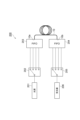
- FIG. 1 is a diagram showing the configuration of a measuring device 1A according to one embodiment of the present disclosure.
- the measuring device 1A is a device that measures the crosstalk between spatial channels of a space division multiplexing (SDM) optical fiber.
- the SDM optical fiber is, for example, a multi-core optical fiber (hereinafter referred to as MCF) or a multi-mode optical fiber.
- MCF multi-core optical fiber
- the SDM optical fiber has multiple spatial channels.
- the multiple spatial channels may be, for example, multiple cores. Alternatively, the multiple spatial channels may be, for example, multiple modes.
- a device for measuring the crosstalk between cores of an MCF 10 as an example of an SDM optical fiber is described.
- the MCF 10 has a first input/output surface 10a and a second input/output surface 10b opposite to the first input/output surface 10a.
- FIG. 2 is a diagram showing a cross section perpendicular to the central axis of the MCF 10.
- the MCF 10 has a glass fiber 11 and a coating resin 12 that coats the outer peripheral surface of the glass fiber 11.
- the glass fiber 11 has N cores as N spatial channels (N is an integer equal to or greater than 2).
- the glass fiber 11 has a cladding 14.
- the glass fiber 11 may have a marker 15.
- the cores 13a, 13b, 13c, and 13d are arranged at equal intervals on concentric circles centered on the central axis of the MCF 10 in a cross section perpendicular to the central axis of the MCF 10.
- the cladding 14 is a common cladding that surrounds the cores 13a, 13b, 13c, and 13d and the marker 15.
- the marker 15 has a different refractive index from the cladding 14.
- ⁇ (km -1 ) is the average value of the transmission loss coefficients of the cores 13a, 13b, 13c, and 13d
- L (km) is the length of the MCF 10.
- the transmission loss ⁇ dB ⁇ L (dB) in the MCF 10 is, for example, 0.01 dB or more.
- the measurement device 1A includes a light source unit 20A, a light detection unit 30A, an optical coupler unit 40, a fan-in/fan-out (FIFO) unit 50, and a calculation unit 60.
- the light source unit 20A emits test light at the first input/output surface 10a, which is incident on each of the cores 13a, 13b, 13c, and 13d.
- the light source unit 20A of this embodiment has a single light source 21 and a first optical switch 22.
- the first optical switch 22 has at least one input port 22a and the same number of output ports 22b, 22c, 22d, and 22e as the number of cores 13a, 13b, 13c, and 13d.
- the first optical switch 22 selectively optically couples the input port 22a to one of the output ports 22b, 22c, 22d, and 22e.
- the input port 22a is optically coupled to the light source 21.
- the optical detector 30A detects light emitted from each of the cores 13a, 13b, 13c, and 13d at the first input/output surface 10a.
- the optical detector 30A of this embodiment has a single optical receiver (power meter) 31 and a second optical switch 32.
- the second optical switch 32 has at least one output port 32a and the same number of input ports 32b, 32c, 32d, and 32e as the cores 13a, 13b, 13c, and 13d.
- the second optical switch 32 selectively optically couples the output port 32a to one of the input ports 32b, 32c, 32d, and 32e.
- the output port 32a is optically coupled to the optical receiver 31.
- the optical coupler unit 40 has three-port optical couplers 41, 42, 43, and 44, which are three-port optical couplers in the same number as the cores 13a, 13b, 13c, and 13d.
- the three-port optical couplers 41, 42, 43, and 44 are, for example, optical circulators.
- FIG. 3 is a diagram showing the configuration of the three-port optical coupler (optical circulator) 41.
- the configurations of the three-port optical couplers 42, 43, and 44 are the same as the configuration of the three-port optical coupler 41.
- the three-port optical coupler 41 has a first port P1, a second port P2, and a third port P3.
- the three-port optical coupler 41 outputs light L1 input to the first port P1 from the second port P2 with low loss, and outputs light L2 input to the second port P2 from the third port P3 with low loss.
- Light L1 input to the first port P1 is hardly output from the third port P3.
- Light L2 input to the second port P2 is hardly output from the first port P1.
- Light input to the third port P3 is hardly output from both the first port P1 and the second port P2.
- the insertion loss from the first port P1 to the second port P2 is, for example, 1 dB or less.
- the insertion loss from the first port P1 to the third port P3 is, for example, 30 dB or more or 40 dB or more.
- the insertion loss from the second port P2 to the third port P3 is, for example, 1 dB or less.
- the insertion loss from the second port P2 to the first port P1 is, for example, 30 dB or more or 40 dB or more.
- the insertion loss from the third port P3 to the first port P1 and the second port P2 is, for example, 30 dB or more or 40 dB or more.
- the first port P1 of each of the three-port optical couplers 41, 42, 43, and 44 is optically coupled to the output ports 22b, 22c, 22d, and 22e of the first optical switch 22. This allows the first optical switch 22 to selectively optically couple the light source 21 to any one of the first ports P1 of the three-port optical couplers 41, 42, 43, and 44.
- the third port P3 of each of the three-port optical couplers 41, 42, 43, and 44 is optically coupled to the input ports 32b, 32c, 32d, and 32e of the second optical switch 32.
- the second optical switch 32 to selectively optically couple the optical receiver 31 to any one of the third ports P3 of the three-port optical couplers 41, 42, 43, and 44.
- three-port optical couplers 41, 42, 43, and 44 are given as examples of three-port optical couplers, but the three-port optical coupler is not limited to this and may be a 1 ⁇ 2 optical fiber coupler or a 2 ⁇ 2 optical fiber coupler in which one port is terminated for reflection suppression.
- the optical fiber coupler may be a waveguide type optical fiber coupler.
- the three-port optical coupler When the three-port optical coupler is a 1x2 optical fiber coupler or a 2x2 optical fiber coupler with one port terminated for reflection suppression, the three-port optical coupler has a first port P1, a second port P2, and a third port P3.
- the three-port optical coupler outputs light L1 input to the first port P1 from the second port P2 with low loss, and outputs light L2 input to the second port P2 from the third port P3 with low loss.
- the light L1 input to the first port P1 is hardly output from the third port P3.
- the light L2 input to the second port P2 is output from the first port P1 with low loss, and the light input to the third port P3 is also output from both the second port P2 with low loss, but there is no significant effect on the measurement.
- the light input to the third port P3 is hardly output from the first port P1.
- the insertion loss between ports P1 and P2, and between ports P2 and P3, which have low insertion losses is higher than that in an optical circulator. This is because, for example, if a 1x2 optical fiber coupler or a 2x2 optical fiber coupler is an optical power splitter with a splitting ratio of 50:50, a theoretical loss of about 3 dB occurs.
- the insertion loss from the first port P1 to the second port P2 is, for example, 4 dB or less.
- the insertion loss from the first port P1 to the third port P3 is, for example, 40 dB or more or 50 dB or more.
- the insertion loss from the second port P2 to the third port P3 is, for example, 4 dB or less.
- the insertion loss from the third port P3 to the first port P1 is, for example, 40 dB or more or 50 dB or more.
- FIFO 50 is an optical component that optically couples each of cores 13a, 13b, 13c, and 13d at the first input/output surface 10a of MCF 10 to the second port P2 of each of three-port optical couplers 41, 42, 43, and 44.
- FIFO 50 has input/output port 50a connected to MCF 10, and input/output ports 50b, 50c, 50d, and 50e connected to the second port P2 of three-port optical couplers 41, 42, 43, and 44, respectively.
- Input/output port 50a of FIFO 50 is formed, for example, by thinning the tips of single-core fibers in the same number as cores 13a, 13b, 13c, and 13d of MCF 10 by etching, and bundling these tips.
- the spacing between the cores of the single-core fibers is the same as the spacing between the cores 13a, 13b, 13c, and 13d of the MCF 10.
- the first ends of the single-core fibers are optically coupled to the cores 13a, 13b, 13c, and 13d, respectively.
- the second ends of the single-core fibers form input/output ports 50b, 50c, 50d, and 50e, respectively, and are optically coupled to the second ports P2 of the three-port optical couplers 41, 42, 43, and 44, respectively.
- the calculation unit 60 calculates the magnitude of inter-core crosstalk based on the detection results of the optical detection unit 30A.
- the calculation unit 60 is configured by a computer including, for example, a CPU, memory, and storage device.
- the storage device stores software for calculating the magnitude of inter-core crosstalk.
- the CPU reads and executes the software to calculate the magnitude of inter-core crosstalk.
- the calculation unit 60 is electrically (or communicatively) connected to the optical receiver 31.
- FIG. 4 is a diagram showing the configuration of a measuring device 1B as a modified example of the measuring device 1A.
- the measuring device 1B has an optical detector 30B instead of the optical detector 30A shown in FIG. 1.
- the optical detector 30B has the same number of optical receivers (power meters) 33, 34, 35, and 36 as the cores 13a, 13b, 13c, and 13d of the MCF 10.
- the optical receivers 33, 34, 35, and 36 are optically coupled to the third ports P3 of the three-port optical couplers 41, 42, 43, and 44, respectively.
- the calculation unit 60 is electrically (or communicatively) connected to the optical receivers 33, 34, 35, and 36.
- FIG. 5 is a diagram showing the configuration of a measuring device 1C as another modified example of the measuring device 1A.
- the measuring device 1C includes a light source unit 20B instead of the light source unit 20A shown in FIG. 1.
- the light source unit 20B has light sources 23, 24, 25, and 26 in the same number as the cores 13a, 13b, 13c, and 13d of the MCF 10.
- the light sources 23, 24, 25, and 26 are optically coupled to the first port P1 of each of the three-port optical couplers 41, 42, 43, and 44.
- the measuring device may include a light detection unit 30B instead of the light detection unit 30A, and a light source unit 20B instead of the light source unit 20A.
- the second input/output surface 10b is provided with a light reflection suppression portion that suppresses the reflection of the test light propagating through each of the cores 13a, 13b, 13c, and 13d from the first input/output surface 10a to the second input/output surface 10b.
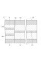
- Figures 6, 7, and 10 to 16 are cross-sectional views showing examples of light reflection suppression portions formed or provided on the second input/output surface 10b, and show cross sections along the central axis AX of the glass fiber 11 of the MCF 10. In these figures, the coating resin 12 is omitted.
- the second input/output surface 10b includes the end surface of the glass fiber 11.
- the reflectance can be defined as Pr/Pi, where Pi is the power of light incident on the light reflecting surface and Pr is the power of light reflected by the light reflecting surface.
- IEC-61300-3-6 defines the return loss as the decibel value of the reflectance (Pr/Pi) multiplied by -1, and also provides an example of a method for measuring the return loss, so the reflectance of the light-reflecting surface can also be measured using the method described in IEC-61300-3-6.
- the reflectance of the light-reflection suppression part can be measured by considering the light-reflection suppression part as a light-reflecting surface.
- the transmission loss ⁇ dB ⁇ L is 0.01 dB or more
- the refractive index n is 1.3 to 2
- the wavelength ⁇ is 1.31 ⁇ m to 1.625 ⁇ m
- w is 2 ⁇ m to 8 ⁇ m.
- RL can be approximated by the following formula (1). Therefore, when RL (dB) satisfies the following formula (2), that is, formula (3), the measurement error ⁇ can be reduced to 1 dB or less.
- the measurement error ⁇ can be reduced to 0.5 dB or less. Furthermore, if the angle ⁇ (degrees) satisfies the following formula (5), the measurement error ⁇ can be reduced to 0.1 dB or less.
- the second incident/exit surface 10b is inclined with respect to an imaginary plane H1 perpendicular to the central axis AX of the MCF 10, thereby reflecting the test light and emitting it to the outside from the side of the glass fiber 11, thereby suppressing reflection of the test light into the glass fiber 11.
- the second incident/exit surface 10b is a flat surface that has been cut or polished.
- the end faces 131 of the cores 13a, 13b, 13c, and 13d are flush with the second incident/exit surface 10b without any steps.
- the centers of the end faces 131 of the cores 13a, 13b, 13c, and 13d are in contact with the imaginary plane H2 at the second incident/exit surface 10b.
- the imaginary plane H2 forms an angle ⁇ with the imaginary plane H1 perpendicular to the central axis AX of the MCF 10.
- the angle ⁇ is an angle defined in radians. In one example, the angle ⁇ is greater than or equal to 4 degrees and less than 90 degrees.
- the second entrance/exit surface 10b also reflects the test light and emits it from the side of the glass fiber 11 to the outside, suppressing reflection of the test light into the glass fiber 11.
- the second entrance/exit surface 10b in this example is not flat, but is a curved surface that is convex toward the outside, i.e., toward the external medium.
- the second entrance/exit surface 10b is formed, for example, by polishing.
- the end surfaces 131 of the cores 13a, 13b, 13c, and 13d are flush with the second entrance/exit surface 10b.
- an imaginary plane H2a that is in contact with the center of the end surfaces 131 of the cores 13a, 13b, 13c, and 13d is defined.
- the imaginary plane H2a forms an angle ⁇ with the imaginary plane H1 that is perpendicular to the central axis AX of the MCF 10.
- the range of the angle ⁇ is the same as that of the embodiment shown in FIG. 6.
- the wavelength of the test light is ⁇ ( ⁇ m)
- the average value of the refractive index of the cores 13a, 13b, 13c, and 13d of the MCF 10 is n
- 0.5 times the average value of the mode field diameter of the cores 13a, 13b, 13c, and 13d is w ( ⁇ m).
- the horizontal axis shows the angle ⁇ (degrees)
- the vertical axis shows the measurement error (dB).
- the second input/output surface 10b is not in contact with a liquid or solid, but is in contact with a gas or vacuum, or the like, whose refractive index can be approximated to 1.
- the horizontal axis shows the angle ⁇ (degrees)
- the vertical axis shows the measurement error (dB).
- the transmission loss ⁇ dB ⁇ L is 0.01 dB or more, the refractive index n is 1.3 or more and 3 or less, the wavelength ⁇ is 1.31 ⁇ m or more and 1.625 ⁇ m or less, and w is 2 ⁇ m or more and 8 ⁇ m or less, the angle ⁇ (degrees) at which the crosstalk measurement error due to reflected light at the second input/output surface 10 b becomes ⁇ (dB) can be approximated by the following formula (6). Therefore, when the angle ⁇ (degrees) satisfies the following formula (7), that is, formula (8), the measurement error ⁇ can be reduced to 1 dB or less.
- the measurement error ⁇ can be reduced to 0.5 dB or less. Furthermore, if the angle ⁇ (degrees) satisfies the following formula (10), the measurement error ⁇ can be reduced to 0.1 dB or less.
- an anti-reflection film 71 (refractive index matching film) is provided on the second input/output surface 10b.
- the anti-reflection film 71 is a solid film containing a material having a refractive index matching the refractive index of the glass fiber 11, and is in contact with the second input/output surface 10b.
- the material constituting the anti-reflection film 71 is, for example, a dielectric material.
- the anti-reflection film 71 constitutes a light reflection suppression section that suppresses reflection of the test light into the glass fiber 11.
- the second incident/exit surface 10b is provided with an anti-reflection material 72.
- the anti-reflection material 72 includes a substance having a refractive index matching that of the glass fiber 11, and is in contact with the second incident/exit surface 10b.
- the anti-reflection material 72 is provided from the second incident/exit surface 10b to the side surface of the glass fiber 11, and surrounds the second incident/exit surface 10b.
- the substance constituting the anti-reflection material 72 is, for example, an alicyclic compound or an aliphatic compound.
- the anti-reflection material 72 may be a solid, liquid, or gel.
- the anti-reflection material 72 constitutes a light reflection suppression section that suppresses reflection of the test light into the glass fiber 11.
- the second input/output surface 10b is immersed in liquid 74.
- the liquid 74 is contained in a container 73 that is open at the top, and the second input/output surface 10b is immersed in the liquid 74 from above.
- the liquid 74 contains a substance having a refractive index that matches the refractive index of the glass fiber 11, and is in contact with the second input/output surface 10b.
- the substance that constitutes the liquid 74 is, for example, an alicyclic compound or an aliphatic compound.
- the liquid 74 constitutes a light reflection suppression section that suppresses reflection of the test light into the glass fiber 11.
- the average value of the refractive indexes of the cores 13a, 13b, 13c and 13d of the MCF 10 is n
- the refractive index of a material having a refractive index matching that of the glass fiber 11 is n0.
- ⁇ (dB) it is better to make the relative refractive index difference ⁇ 0 small.
- the measurement error ⁇ can be reduced to 1 dB or less. Furthermore, when the relationship between the relative refractive index difference ⁇ 0 and ⁇ dB ⁇ L (dB) satisfies the following formula (12), the measurement error ⁇ can be reduced to 0.5 dB or less. Furthermore, when the relationship between the relative refractive index difference ⁇ 0 and ⁇ dB ⁇ L (dB) satisfies the following formula (13), the measurement error ⁇ can be reduced to 0.1 dB or less.
- the measuring device 1A, 1B or 1C further includes an anti-reflection device 80 provided on the second input/output surface 10b of the MCF 10.
- the anti-reflection device 80 includes an MCF 81 separate from the MCF 10, and an anti-reflection film 82 provided on the first end surface 81a of the MCF 81.
- the anti-reflection film 82 is, for example, a dielectric multilayer film.
- the second end surface of the MCF 81 is connected to the second input/output surface 10b.
- the MCF 81 has the same number of cores as the cores 13a, 13b, 13c, and 13d of the MCF 10 (only two cores 83a and 83b are shown in the figure), and these cores are optically coupled to the cores 13a, 13b, 13c, and 13d of the MCF 10, respectively.
- the connection between the MCF 81 and the MCF 10 may be a fusion connection or a connection using an optical connector.
- the anti-reflection film 82 constitutes a light reflection suppression section that suppresses the reflection of the test light into the glass fiber 11.
- the measuring device 1A, 1B or 1C further includes an anti-reflection device 90 provided on the second input/output surface 10b of the MCF 10.
- the anti-reflection device 90 has single-core optical fibers (SCFs) 92, the number of which is the same as the number of cores 13a, 13b, 13c, and 13d of the MCF 10, and a FIFO 91.
- the first end surface 92a of each SCF 92 is provided with an anti-reflection film 93 as a light reflection suppression unit that suppresses reflection of the test light into the SCF 92.
- the anti-reflection film 93 is, for example, a dielectric multilayer film.
- the second end surface of each SCF 92 is optically coupled to the cores 13a, 13b, 13c, and 13d at the second input/output surface 10b via the FIFO 91.
- the measuring device 1A, 1B or 1C further includes another optical fiber 100 as a light reflection suppression unit provided on the second input/output surface 10b of the MCF 10.
- the optical fiber 100 has a clad 104 that mainly contains the same material as the clad 14 of the MCF 10, and a coating resin 102 that coats the clad 104.
- a first end face of the optical fiber 100 is fusion-spliced to the second input/output surface 10b of the MCF 10.
- a second end face of the optical fiber 100 is open.
- the optical fiber 100 does not have a single core. That is, the glass fiber of the optical fiber 100 consists only of the clad 104.
- the optical fiber 100 does not have any spatial channel (core) that is aligned with the cores 13a, 13b, 13c, or 13d of the MCF 10.
- the cores 13a, 13b, 13c, and 13d of the MCF 10 are in contact only with the cladding 104 of the optical fiber 100.
- the measuring device 1A, 1B or 1C further includes another optical fiber 110 as a light reflection suppression unit provided on the second input/output surface 10b of the MCF 10.
- the optical fiber 110 has a core 113, a clad 114 that covers the core 113 and mainly contains the same material as the clad 14 of the MCF 10, and a coating resin 112 that covers the clad 114.
- a first end face of the optical fiber 110 is fusion-spliced to the second input/output surface 10b of the MCF 10.
- a second end face of the optical fiber 110 is open.
- the core 113 is not aligned with any of the cores 13a, 13b, 13c, or 13d of the MCF 10.
- the optical fiber 110 does not have any spatial channel aligned with the cores 13a, 13b, 13c, or 13d of the MCF 10.
- the cores 13a, 13b, 13c, and 13d of the MCF 10 are in contact only with the cladding 114 of the optical fiber 110.
- the test light output from the light source unit 20A may be either continuous light or chopped light.
- FIG. 17 is a graph showing a schematic diagram of the optical power waveform of continuous light. When the test light is continuous light, its optical power is constant regardless of time. When the test light is continuous light, a general optical power meter can be used as the optical receivers 31, 33, 34, and 35.
- FIG. 18 is a graph showing a schematic diagram of the optical power waveform of chopped light. When the test light is chopped light, its optical power waveform is a rectangular wave. The duty ratio (the ratio of the time when the optical power is at its peak to the total time) is, for example, 0.5 or 0.25. When the test light is chopped light, an optical power meter compatible with chopping detection (synchronous detection/phase detection) can be used as the optical receivers 31, 33, 34, and 35 to perform detection with reduced measurement noise caused by ambient light, etc., and to improve detection sensitivity.
- chopping detection synchronous detection/phase detection
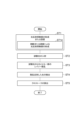
- Figure 19 is a flowchart showing the method for measuring crosstalk between spatial channels according to this embodiment.
- step ST1 a light reflection suppression portion is formed or provided on the second incident/exit surface 10b.
- the light reflection suppression portion are as described in Figures 6 to 16. That is, step ST1 may include step ST11 of providing an anti-reflection film 71 (see Figure 10) or an anti-reflection material 72 (see Figure 11) on the second incident/exit surface 10b, or immersing the second incident/exit surface 10b in a liquid 74 (see Figure 12).
- step ST2 test light is incident from light source unit 20A or 20B to one of cores 13a, 13b, 13c, and 13d (first spatial channel, core 13a as an example here) at first input/output surface 10a.
- light source unit 20A switches first optical switch 22 to incident test light to core 13a.
- First optical switch 22 may be switched by a control signal from calculation unit 60 or may be switched manually.
- light source unit 20B (see Figure 5) incidents test light from light source 23, among light sources 23, 24, 25, and 26, which corresponds to core 13a.
- step ST3 at least a portion of the test light is backscattered inside the MCF 10 by Rayleigh scattering.
- step ST4 a part of the light that is Rayleigh scattered backward inside the MCF 10 is emitted from the core 13a, and another part is emitted from a core other than the core 13a (a second spatial channel or a second core, here, each of the cores 13b, 13c, and 13d) due to inter-core crosstalk.
- a first optical power which is the power of the light emitted from the core 13a
- a second optical power which is the power of the light emitted from each of the cores 13b, 13c, and 13d
- the optical detection unit 30A switches the second optical switch 32 to sequentially input the light from the cores 13a, 13b, 13c, and 13d to the optical receiver 31.
- the second optical switch 32 may be switched by a control signal from the calculation unit 60, or may be switched manually.
- light detection unit 30B see FIG. 4
- light from cores 13a, 13b, 13c, and 13d is made incident on light receivers 33, 34, 35, and 36, which correspond to cores 13a, 13b, 13c, and 13d, respectively.
- the first optical power is the sum of the optical power components emitted from core 13a (first spatial channel) among the return optical power components of the test light including backscattered light at each longitudinal position of MCF 10.
- the second optical power is the sum of the optical power components emitted from cores 13b, 13c, and 13d (second spatial channel) among the return optical power components of the test light including backscattered light at each longitudinal position of MCF 10.
- step ST5 the magnitude of crosstalk between the core 13a and the cores 13b, 13c, and 13d is calculated based on the first optical power and the second optical power in the calculation unit 60.
- the magnitude XT of the crosstalk between the core 13a and the cores 13b, 13c, and 13d is calculated based on the first optical power PW1 and the second optical power PW2, for example, by the following formula (14).
- ⁇ (km ⁇ 1 ) is the average value of the transmission loss coefficients of the cores 13 a , 13 b , 13 c , and 13 d
- L (km) is the length of the MCF 10 .
- the power of the light emitted from core 13a at the first input/output surface 10a is measured. At this time, the light emitted from core 13a contains almost no light reflected at the second input/output surface 10b, and mainly contains light that has undergone backward Rayleigh scattering inside the MCF 10.
- the power of the light emitted from each of cores 13b, 13c, and 13d at the first input/output surface 10a is measured. At this time, the light emitted from each of cores 13b, 13c, and 13d contains almost no light reflected at the second input/output surface 10b, and mainly contains light that has undergone backward Rayleigh scattering inside the MCF 10.
- steps ST2 to ST5 are repeated in sequence with the first core (first spatial channel) into which the test light is incident being cores 13a, 13b, 13c, and 13d.
- FIG. 20 is a flow chart showing a modified example of the method for measuring spatial channel crosstalk.
- step ST1 of forming or providing a light reflection suppressing portion on the second input/output surface 10b includes step ST12 instead of step ST11 described above.
- step ST12 as shown in FIG. 13, the second end surface of the MCF 81, which has an anti-reflection film 82 provided on the first end surface 81a as a light reflection suppressing portion, is connected to the second input/output surface 10b.
- FIG. 21 is a flow chart showing another modified example of the spatial channel crosstalk measuring method.
- step ST1 of forming or providing an optical reflection suppressing portion on the second input/output surface 10b includes step ST13 instead of step ST11 described above.
- step ST13 as shown in FIG. 14, the second end face of each of the multiple SCFs 92, which has an anti-reflection film 93 provided on the first end face 92a as an optical reflection suppressing portion, is optically coupled to the cores 13a, 13b, 13c, and 13d at the second input/output surface 10b.
- FIG. 22 is a flow chart showing yet another modified example of the method for measuring crosstalk between spatial channels.
- step ST1 of forming or providing a light reflection suppression portion on the second incident/exit surface 10b includes step ST14 instead of step ST11 described above.
- step ST14 as shown in FIG. 6 or FIG. 7, the second incident/exit surface 10b is polished or cut to a flat surface or a curved surface, which is used as the light reflection suppression portion.
- the second incident/exit surface 10b that is substantially flat and is simply cut may be used as the light reflection suppression portion.
- FIG. 23 is a flow chart showing yet another modified example of the spatial channel crosstalk measurement method.
- step ST1 of forming or providing a light reflection suppression portion on the second input/output surface 10b includes step ST15 instead of step ST11 described above.
- step ST15 as shown in FIG. 15 or FIG. 16, an optical fiber 100 or 110 serving as a light reflection suppression portion is fusion spliced to the second input/output surface 10b.
- FIG. 24 is a diagram showing a schematic configuration of a measurement device 200 according to a reference example.
- the measurement device 200 shown in FIG. 24 is a device for measuring inter-core crosstalk of MCF 10, and includes a single light source 201, a first optical switch 202, a FIFO 203, a FIFO 204, a second optical switch 205, and a single optical receiver 206.
- the light source 201, the first optical switch 202, and the FIFO 203 are connected to the first input/output surface 10a of the MCF 10.
- the FIFO 204, the second optical switch 205, and the optical receiver 206 are connected to the second input/output surface 10b of the MCF 10.
- the test light output from the light source 201 is incident on the first input/output surface 10a to a first core (first spatial channel) selected by the first optical switch 202 from among the multiple cores of the MCF 10.
- the second optical switch 205 sequentially selects the first core to which the test light is incident and a second core (second spatial channel) different from the first core.
- the optical power of the test light propagated through the first core and the optical power of the crosstalk light propagated through the second core are detected by the optical receiver 206. Based on these optical powers, the inter-core crosstalk is calculated.
- test light is incident on the first core at the first input/output surface 10a of the MCF 10, and the power of the test light emitted from the first core and the second core is detected at the second input/output surface 10b of the MCF 10.
- the MCF 10 to be measured it may not be easy to connect the unit consisting of the light source 201, the first optical switch 202, and the FIFO 203 to the first input/output surface 10a of the MCF 10, and to connect the unit consisting of the FIFO 204, the second optical switch 205, and the photodetector 206 to the second input/output surface 10b of the MCF 10, which is far away from the first input/output surface 10a.
- the measurement devices 1A, 1B, and 1C and the measurement method of this embodiment it is sufficient to connect the light source unit 20A or 20B and the light detection unit 30A or 30B to the first input/output surface 10a of the MCF 10, and there is no need to connect any of them to the second input/output surface 10b. Therefore, even if the first input/output surface 10a and the second input/output surface 10b are separated by several kilometers or more in the MCF 10, the light source unit 20A or 20B and the light detection unit 30A or 30B can be easily connected to the MCF 10. Furthermore, by halving the number of connections in the measurement, the crosstalk measurement of the MCF 10 can be performed efficiently.
- the level of the detection signal can be increased and the measurement accuracy of the crosstalk can be improved by detecting, for example, the sum of the backward Rayleigh scattered light.
- the light reflection suppression section is not provided, a part of the test light may be reflected at the second entrance/exit surface 10b, and the reflected test light may be mixed into the backward Rayleigh scattered light. Since the power of the backward Rayleigh scattered light is very small, in such a case, the accuracy of the crosstalk measurement may not be improved.
- a light reflection suppression section that suppresses the reflection of the test light is formed or provided on the second entrance/exit surface 10b. This reduces the reflection of a part of the test light at the second entrance/exit surface 10b, and therefore reduces the mixing of reflected light into the backward Rayleigh scattered light. Therefore, the inter-channel crosstalk can be measured with high accuracy.
- the magnitude of crosstalk XT may be calculated using formula (14). For example, by using such a calculation formula, the magnitude of crosstalk can be calculated from only the sum of the power of the backward Rayleigh scattered light from the first entrance/exit surface 10a to the second entrance/exit surface 10b.
- ⁇ dB ⁇ L (dB) may be 0.01 dB or more, so that backward Rayleigh scattered light having a sufficiently measurable level of power can be returned to the first input/output surface 10 a.
- the return loss RL (dB) of the reflection at the second input/output surface 10b may satisfy formula (3). This makes it possible to reduce the measurement error caused by the reflection of the test light at the second input/output surface 10b to 1 dB or less.
- the light reflection suppression section may suppress reflection of the test light at the second input/output surface 10b of the MCF 10.
- the angle ⁇ (degrees) between the imaginary plane H2 and the imaginary plane H1 shown in FIG. 6 may satisfy formula (16). This allows the measurement error caused by the reflection of the test light at the second input/output surface 10b to be reduced to 1 dB or less.
- step ST1 of forming or providing a light reflection suppression portion on the second incident/exit surface 10b may include step ST14 of forming the light reflection suppression portion by forming the second incident/exit surface 10b by fracturing the MCF 10. This makes it possible to easily form the light reflection suppression portion on the second incident/exit surface 10b.
- step ST1 of forming or providing a light reflection suppression portion on the second incident/exit surface 10b may include step ST14 of forming a light reflection suppression portion by polishing the second incident/exit surface 10b of the MCF 10. This makes it possible to easily form a light reflection suppression portion on the second incident/exit surface 10b.
- the light reflection suppression portion may include a material that is in contact with the second input/output surface 10b of the MCF 10 and has a refractive index that matches the refractive index of the MCF 10.
- step ST1 of forming or providing a light reflection suppression portion on the second input/output surface 10b may include step ST11 of providing a light reflection suppression portion by contacting the second input/output surface 10b of the MCF 10 with a material that has a refractive index that matches the refractive index of the MCF 10. This makes it possible to easily provide a light reflection suppression portion on the second input/output surface 10b.
- the material having a refractive index matching that of MCF10 may be a liquid, gel, or solid.
- the light reflection suppression portion may have another optical fiber 100 (or 110) having a cladding 104 (or 114) that mainly contains the same material as the cladding 14 of the MCF 10.
- Step ST1 may include step ST15 of fusion splicing the end face of the optical fiber 100 (or 110) to the second input/output face 10b of the MCF 10.
- the optical fiber 100 (or 110) after fusion splicing may not have spatial channels (cores) that are aligned with the cores 13a, 13b, 13c, and 13d of the MCF 10. This makes it possible to easily provide a light reflection suppression portion at the second input/output face 10b.
- the measuring devices 1A, 1B, and 1C may include an MCF 81 having an anti-reflection film 82 as a light reflection suppression unit provided on a first end face 81a.
- the second end face of the MCF 81 is connected to the second input/output face 10b at the second input/output face 10b.
- step ST1 may include step ST12 of connecting the second end face of the MCF 81 having an anti-reflection film 82 as a light reflection suppression unit provided on the first end face 81a to the second input/output face 10b.
- the measuring apparatuses 1A, 1B, and 1C may include SCFs 92 having the same number as the cores 13a, 13b, 13c, and 13d, and having an anti-reflection film 93 as an optical reflection suppression portion provided on the first end face 92a.
- the second end face of each SCF 92 is optically coupled to each of the cores 13a, 13b, 13c, and 13d at the second input/output face 10b.
- step ST1 may include step ST13 of optically coupling the second end face of each SCF 92 having the same number as the cores 13a, 13b, 13c, and 13d, and having an anti-reflection film 93 as an optical reflection suppression portion provided on the first end face 92a, to each of the cores 13a, 13b, 13c, and 13d at the second input/output face 10b.
- the reflectance at the optical reflection suppression portion can be reduced, and crosstalk can be measured more accurately.
- there is no need to provide an anti-reflection film on the second input/output surface 10b and it is sufficient to simply connect an optical component such as a FIFO 91 to the second input/output surface 10b, making the measurement process easier.
- the second input/output surface 10b may be used as a light reflection suppression section. This eliminates the need for special devices such as anti-reflection devices 80 and 90, and simplifies the configuration of the measuring device.
- the measuring devices 1A, 1B and 1C may include three-port optical couplers 41, 42, 43, 44 and a FIFO 50.
- the three-port optical couplers 41, 42, 43, 44 have a first port P1, a second port P2 and a third port P3, and output light input to the first port P1 from the second port P2, and output light input to the second port P2 from the third port P3.
- the FIFO 50 optically couples each of the cores 13a, 13b, 13c, 13d at the first input/output surface 10a of the MCF 10 to the second port P2 of each of the three-port optical couplers 41, 42, 43, 44.
- the light source unit 20A or 20B is optically coupled to the first port P1 of the three-port optical couplers 41, 42, 43, 44.
- the optical detection unit 30A or 30B is optically coupled to the third port P3 of the three-port optical coupler 41, 42, 43, 44. This allows for a simple configuration in which test light from the light source unit 20A or 20B is incident on each of the cores 13a, 13b, 13c, 13d, and the light emitted from the core to which the test light is incident and the light emitted from another core are detected by the optical detection unit 30A or 30B.
- the light source unit 20B has the same number of light sources 23, 24, 25, and 26 as the cores 13a, 13b, 13c, and 13d, and each of the light sources 23, 24, 25, and 26 may be optically coupled to the first port P1 of each of the three-port optical couplers 41, 42, 43, and 44. This allows test light to be input to the first port P1 of each of the three-port optical couplers 41, 42, 43, and 44 with a simple configuration.
- the light source unit 20A may have a single light source 21 and a first optical switch 22 that selectively optically couples the single light source 21 to a first port P1 of any one of the three-port optical couplers 41, 42, 43, and 44. This makes it possible to reduce the number of light sources.
- the optical detection unit 30B has the same number of optical receivers 33, 34, 35, 36 as the cores 13a, 13b, 13c, 13d, and each of the optical receivers 33, 34, 35, 36 may be optically coupled to the third port P3 of each of the three-port optical couplers 41, 42, 43, 44. This makes it possible to detect the light output from the third port P3 of each of the three-port optical couplers 41, 42, 43, 44 with a simple configuration.
- the optical detection unit 30A may have a single optical receiver 31 and a second optical switch 32 that selectively optically couples the single optical receiver 31 to the third port P3 of any one of the three-port optical couplers 41, 42, 43, and 44. This makes it possible to reduce the number of optical receivers.
- the inter-core crosstalk of the FIFO 50 may be 0.259 times or less, 0.122 times or less, 0.047 times or less, or 0.023 times or less of the inter-core crosstalk of the MCF 10. This allows the inter-core crosstalk measurement error of the MCF 10 caused by the inter-core crosstalk of the FIFO 50 to be 1 dB or less, 0.5 dB or less, 0.2 dB or less, or 0.1 dB or less, respectively, and allows the inter-core crosstalk of the MCF 10 to be measured with greater accuracy.
- the spatial channel crosstalk measuring method and spatial channel crosstalk measuring device according to the present disclosure are not limited to the above-described embodiment and each of the modified examples, and various other modifications are possible.
- the shape of the light reflection suppression portion on the second input/output surface 10b of the MCF 10 is not limited to the above-described embodiment.
- the number of cores of the MCF 10 is also not limited to the above-described embodiment.
- Multi-core optical fiber 10a...first input/output surface 10b...second input/output surface 11...glass fiber 12...coating resin 13a, 13b, 13c, 13d...core 14...clad 15...marker 20A, 20B...light source section 21, 23, 24, 25, 26...light source 22...first optical switch 22a...input port 22b, 22c, 22d, 22e...output port 30A, 30B...light detection section 31...photoreceiver 32...second optical switch 32a...output port 32b, 32c, 32d, 32e...input port 33, 34, 35, 36...photoreceiver 40...optical coupler section 41, 42, 43, 44...three-port optical coupler 50...FIFO 50a, 50b, 50c, 50d, 50e...
- Input/output port 60 Calculation unit 71... Anti-reflection film 72... Anti-reflection material 73... Container 74... Liquid 80, 90... Anti-reflection device 81... Multi-core optical fiber (MCF) 81a, 92a...first end faces 82, 93...anti-reflection coating 91...FIFO 92... Single-core optical fiber 100, 110... Optical fiber 102, 112... Coating resin 104, 114... Cladding 113... Core 131... End face 200... Measuring device 201... Light source 202... First optical switch 203, 204...
- MCF Multi-core optical fiber
- FIFO 205 ...Second optical switch 206...Optical receiver AX...Central axis H1, H2, H2a...Imaginary plane L1, L2...Light P1...First port P2...Second port P3...Third port ST1, ST2, ST3, ST4, ST5, ST11, ST12, ST13, ST14, ST15...Step ⁇ ...Angle
Landscapes
- Physics & Mathematics (AREA)
- Optics & Photonics (AREA)
- General Physics & Mathematics (AREA)
- Chemical & Material Sciences (AREA)
- Analytical Chemistry (AREA)
- Electromagnetism (AREA)
- Engineering & Computer Science (AREA)
- Computer Networks & Wireless Communication (AREA)
- Signal Processing (AREA)
- Testing Of Optical Devices Or Fibers (AREA)
Priority Applications (3)
| Application Number | Priority Date | Filing Date | Title |
|---|---|---|---|
| JP2025501193A JPWO2024172092A1 (https=) | 2023-02-15 | 2024-02-14 | |
| EP24756932.0A EP4667893A1 (en) | 2023-02-15 | 2024-02-14 | Method for measuring crosstalk between spatial channels, and device for measuring crosstalk between spatial channels |
| CN202480012120.5A CN120677364A (zh) | 2023-02-15 | 2024-02-14 | 空间信道间串扰测定方法及空间信道间串扰测定装置 |
Applications Claiming Priority (2)
| Application Number | Priority Date | Filing Date | Title |
|---|---|---|---|
| JP2023021827 | 2023-02-15 | ||
| JP2023-021827 | 2023-02-15 |
Publications (1)
| Publication Number | Publication Date |
|---|---|
| WO2024172092A1 true WO2024172092A1 (ja) | 2024-08-22 |
Family
ID=92420048
Family Applications (2)
| Application Number | Title | Priority Date | Filing Date |
|---|---|---|---|
| PCT/JP2024/005112 Ceased WO2024172092A1 (ja) | 2023-02-15 | 2024-02-14 | 空間チャネル間クロストーク測定方法および空間チャネル間クロストーク測定装置 |
| PCT/JP2024/005111 Ceased WO2024172091A1 (ja) | 2023-02-15 | 2024-02-14 | 空間チャネル間クロストーク測定方法、マルチコア光ファイバのコア間クロストーク測定方法、空間チャネル間クロストーク測定装置、およびマルチコア光ファイバのコア間クロストーク測定装置 |
Family Applications After (1)
| Application Number | Title | Priority Date | Filing Date |
|---|---|---|---|
| PCT/JP2024/005111 Ceased WO2024172091A1 (ja) | 2023-02-15 | 2024-02-14 | 空間チャネル間クロストーク測定方法、マルチコア光ファイバのコア間クロストーク測定方法、空間チャネル間クロストーク測定装置、およびマルチコア光ファイバのコア間クロストーク測定装置 |
Country Status (4)
| Country | Link |
|---|---|
| EP (2) | EP4667893A1 (https=) |
| JP (2) | JPWO2024172092A1 (https=) |
| CN (2) | CN120677365A (https=) |
| WO (2) | WO2024172092A1 (https=) |
Citations (3)
| Publication number | Priority date | Publication date | Assignee | Title |
|---|---|---|---|---|
| WO2012115162A1 (ja) | 2011-02-25 | 2012-08-30 | 住友電気工業株式会社 | マルチコア光ファイバから出力される光の受光方法、及び、分離装置 |
| WO2022201474A1 (ja) * | 2021-03-25 | 2022-09-29 | 日本電信電話株式会社 | 多心無反射終端部および光線路試験方法 |
| JP2023021827A (ja) | 2021-08-02 | 2023-02-14 | 株式会社アトラス | 飲料容器および蓋体 |
Family Cites Families (3)
| Publication number | Priority date | Publication date | Assignee | Title |
|---|---|---|---|---|
| JP2001083040A (ja) * | 1999-09-16 | 2001-03-30 | Hitachi Cable Ltd | 光ファイバケーブルの試験方法 |
| US20020101577A1 (en) * | 2001-01-30 | 2002-08-01 | Thwing Theodore N. | Optical fiber test method and apparatus |
| JP2006067014A (ja) * | 2004-08-24 | 2006-03-09 | Sumitomo Electric Ind Ltd | 光通信機器および光伝送システム |
-
2024
- 2024-02-14 EP EP24756932.0A patent/EP4667893A1/en active Pending
- 2024-02-14 EP EP24756931.2A patent/EP4667892A1/en active Pending
- 2024-02-14 WO PCT/JP2024/005112 patent/WO2024172092A1/ja not_active Ceased
- 2024-02-14 WO PCT/JP2024/005111 patent/WO2024172091A1/ja not_active Ceased
- 2024-02-14 CN CN202480012317.9A patent/CN120677365A/zh active Pending
- 2024-02-14 JP JP2025501193A patent/JPWO2024172092A1/ja active Pending
- 2024-02-14 CN CN202480012120.5A patent/CN120677364A/zh active Pending
- 2024-02-14 JP JP2025501192A patent/JPWO2024172091A1/ja active Pending
Patent Citations (3)
| Publication number | Priority date | Publication date | Assignee | Title |
|---|---|---|---|---|
| WO2012115162A1 (ja) | 2011-02-25 | 2012-08-30 | 住友電気工業株式会社 | マルチコア光ファイバから出力される光の受光方法、及び、分離装置 |
| WO2022201474A1 (ja) * | 2021-03-25 | 2022-09-29 | 日本電信電話株式会社 | 多心無反射終端部および光線路試験方法 |
| JP2023021827A (ja) | 2021-08-02 | 2023-02-14 | 株式会社アトラス | 飲料容器および蓋体 |
Non-Patent Citations (4)
| Title |
|---|
| KOBAYASHI YUTO, INOUE AYUMI, SUGANUMA TAKAHIRO, NAGASHIMA TAKUJI, HAYASHI TETSUYA, HASEGAWA TAKEMI: "Measurement of Inter-core Crosstalk of Multicore Fibers with Optical Time Domain Reflectometry ", SUMITOMO ELECTRIC TECHNICAL REVIEW, 1 April 2023 (2023-04-01), pages 1 - 6, XP093125356, [retrieved on 20240130] * |
| MASATAKA NAKAZAWA ET AL.: "Nondestructive measurement of mode couplings along a multi-core fiber using a synchronous multi channel OTDR", OPTICS EXPRESS, vol. 20, no. 11, 2012 |
| See also references of EP4667893A1 |
| TETSUYA HAYASHI ET AL.: "Characterization of Crosstalk in Ultra-Low-Crosstalk Multi-Core Fiber", JOURNAL OF LIGHTWAVE TECHNOLOGY, vol. 30, no. 4, 2012 |
Also Published As
| Publication number | Publication date |
|---|---|
| EP4667892A1 (en) | 2025-12-24 |
| CN120677364A (zh) | 2025-09-19 |
| CN120677365A (zh) | 2025-09-19 |
| JPWO2024172091A1 (https=) | 2024-08-22 |
| WO2024172091A1 (ja) | 2024-08-22 |
| EP4667893A1 (en) | 2025-12-24 |
| JPWO2024172092A1 (https=) | 2024-08-22 |
Similar Documents
| Publication | Publication Date | Title |
|---|---|---|
| CN109416438B (zh) | 光纤评价方法和光纤评价装置 | |
| US4474431A (en) | Optical fibre directional coupler | |
| JP2002323408A (ja) | 光ファイバをテストするための装置およびその方法 | |
| US4818071A (en) | Fiber optic doppler anemometer | |
| JP2012189580A (ja) | マルチコア光ファイバから出力される光の受光方法、及び、分離装置 | |
| AU2017373550A1 (en) | Waveguide interferometer | |
| CN103743551B (zh) | 一种多功能铌酸锂集成器件的光学性能测量方法 | |
| US7773640B2 (en) | Fiber laser device | |
| CN101329198B (zh) | 一种光器件回波损耗测量方法 | |
| CN106441544B (zh) | 一种便携式光学测量仪器 | |
| US6445854B1 (en) | Optical fiber having first and second reflective surfaces and method of operation | |
| JP2008170327A (ja) | 屈折率検出装置、および、液位検出装置 | |
| US6222960B1 (en) | Optical element using multimode interference | |
| WO2024172092A1 (ja) | 空間チャネル間クロストーク測定方法および空間チャネル間クロストーク測定装置 | |
| JP7661585B2 (ja) | センシングケーブルおよびセンシングシステム | |
| CN112213897A (zh) | 光学调制器和光学测量设备 | |
| JPS63179304A (ja) | 反射形光応用センサシステムの光コネクタ | |
| JPWO2024172091A5 (https=) | ||
| US6519392B2 (en) | Optical tap collimator using an uncoated GRIN lens | |
| JPWO2024172092A5 (https=) | ||
| CN115885201A (zh) | 用于磁光式电流传感器的光导 | |
| CN102621347B (zh) | 一种与光纤陀螺兼容的反射式光纤加速度计 | |
| JP2511999B2 (ja) | 液体検知用光ファイバおよびこれを用いた液体検知システム | |
| JP2025002425A (ja) | クロストーク測定方法、クロストーク測定装置、光損失測定方法、及び光損失測定装置。 | |
| Yamaguchi et al. | Single-End Crosstalk Measurement Method for Multi-Core Fibers Using Continuous Light Source |
Legal Events
| Date | Code | Title | Description |
|---|---|---|---|
| 121 | Ep: the epo has been informed by wipo that ep was designated in this application |
Ref document number: 24756932 Country of ref document: EP Kind code of ref document: A1 |
|
| ENP | Entry into the national phase |
Ref document number: 2025501193 Country of ref document: JP Kind code of ref document: A |
|
| WWE | Wipo information: entry into national phase |
Ref document number: 2025501193 Country of ref document: JP |
|
| WWE | Wipo information: entry into national phase |
Ref document number: 202480012120.5 Country of ref document: CN |
|
| WWE | Wipo information: entry into national phase |
Ref document number: 2024756932 Country of ref document: EP |
|
| NENP | Non-entry into the national phase |
Ref country code: DE |
|
| WWP | Wipo information: published in national office |
Ref document number: 202480012120.5 Country of ref document: CN |
|
| ENP | Entry into the national phase |
Ref document number: 2024756932 Country of ref document: EP Effective date: 20250915 |
|
| WWP | Wipo information: published in national office |
Ref document number: 2024756932 Country of ref document: EP |