WO2024172090A1 - バルーン及びバルーンカテーテル - Google Patents
バルーン及びバルーンカテーテル Download PDFInfo
- Publication number
- WO2024172090A1 WO2024172090A1 PCT/JP2024/005110 JP2024005110W WO2024172090A1 WO 2024172090 A1 WO2024172090 A1 WO 2024172090A1 JP 2024005110 W JP2024005110 W JP 2024005110W WO 2024172090 A1 WO2024172090 A1 WO 2024172090A1
- Authority
- WO
- WIPO (PCT)
- Prior art keywords
- balloon
- blade
- cutting blade
- catheter
- cutting
- Prior art date
- Legal status (The legal status is an assumption and is not a legal conclusion. Google has not performed a legal analysis and makes no representation as to the accuracy of the status listed.)
- Ceased
Links
Images


Classifications
-
- A—HUMAN NECESSITIES
- A61—MEDICAL OR VETERINARY SCIENCE; HYGIENE
- A61M—DEVICES FOR INTRODUCING MEDIA INTO, OR ONTO, THE BODY; DEVICES FOR TRANSDUCING BODY MEDIA OR FOR TAKING MEDIA FROM THE BODY; DEVICES FOR PRODUCING OR ENDING SLEEP OR STUPOR
- A61M25/00—Catheters; Hollow probes
- A61M25/10—Balloon catheters
Definitions
- the present invention relates to a balloon and a balloon catheter.
- balloon catheters are used to expand the lesions in the coronary arteries to improve blood flow.
- Balloon catheters are also used in PTA (percutaneous transluminal angioplasty), which treats arteriosclerosis that has developed in the femoral artery, iliac artery, popliteal artery, and below-the-knee artery of the lower limbs, and in VAIVT (vascular access interventional therapy), which treats stenosis and blockage of the vascular access of the upper limbs.
- PTA percutaneous transluminal angioplasty
- VAIVT vascular access interventional therapy
- a cutting balloon catheter with a blade on the balloon is known as a device that makes treatment possible in such cases.
- a cutting balloon catheter has a blade-like blade on the outer periphery of the balloon, and this blade can create cracks in the calcified area, making it easier to widen the lumen of the affected area.
- An example of such a balloon catheter with a blade is shown in Patent Document 1.
- the balloon catheter in Patent Document 1 has a balloon made of a high elasticity and high rigidity material connected to a catheter placed near the lesion in the blood vessel, and the balloon has flexible cutting blades whose number and position can be changed.
- the increased flexibility improves catheter tracking and delivery in a tortuous living body, and has the effect of allowing the catheter to be advanced over a guidewire to lesions in the cardiovascular cavity and the like that are difficult to reach with a low-flexibility catheter, and the lesion can be removed.
- the cutting blade described in Patent Document 1 has a metal blade that is extended to the longitudinal end, and therefore there is a risk that the end of the metal blade will pierce and get stuck in lesions such as plaque or calcification. There is also a problem that the end of the metal blade may come into contact with blood vessels other than the lesion when inserting or removing the balloon, causing damage.
- the present invention has been made to solve the above-mentioned problems, and aims to provide a balloon for a catheter and a balloon catheter that reduce the risk of the blade getting stuck in a lesion while maintaining cutting performance.
- the balloon and balloon catheter of the present invention employ the following means.
- the balloon according to the present invention is a balloon used in a balloon catheter,
- One or more cutting blades are provided on the outer circumferential surface of the balloon in parallel with the longitudinal direction of the balloon,
- the cutting blade is characterized in that an end forming portion is provided at either end in the longitudinal direction of the cutting blade, the end forming portion being formed at the same height as the end of the cutting blade or higher than the end of the cutting blade.
- the end forming portion may be formed so as to cover a part of the cutting blade tip.
- the end forming portion may be formed so that its height gradually decreases toward the tip.
- the cutting blade may be attached to a resin base, and the end forming portion may be molded integrally with the base portion.
- the cutting blade may be formed by dividing it into multiple parts in the longitudinal direction. By dividing the cutting blade into multiple parts, it becomes easier to curve the balloon, and it becomes easier to follow the curved inside of the blood vessel.
- the cutting blade may be characterized by an alternating arrangement of metal blades and resin blades.
- the present invention further provides a balloon catheter having the balloon described above.
- a balloon catheter having the balloon described above.
- Such a balloon catheter can provide the effects described above.
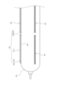
- FIG. 1 is a side view showing a schematic diagram of one embodiment of a balloon catheter 100 according to the present invention.
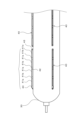
- FIG. 2 is a side view showing a schematic diagram of the balloon 30 of the balloon catheter 100 according to the present invention.
- 1 is a side view showing a schematic diagram of a cutting blade 40 used in a balloon catheter 100 according to the present invention.
- FIG. 1 is a side view showing a schematic diagram of another embodiment of the cutting blade 40 of the balloon catheter according to the present invention.
- FIG. 1 is a side view showing a schematic diagram of another embodiment of the cutting blade 40 of the balloon catheter according to the present invention.
- FIG. FIG. 1 is a schematic diagram showing a balloon catheter according to the present invention in use.
- FIG. 1 is a side view showing a schematic diagram of a balloon catheter 100 according to an embodiment.
- the balloon catheter 100 according to the present invention mainly comprises a catheter shaft 10, a balloon 30, and an operating member 60 provided at the proximal end of the balloon catheter 100.
- the cutting blade 40 is drawn larger than the actual scale relative to the size of the balloon for ease of illustration.
- the explanation of the balloon catheter 100 includes an explanation of the balloon 30 according to the present invention, so the explanation of the balloon will replace the explanation of the balloon catheter 100.
- an RX type rapid exchange type
- an over-the-wire type may also be used.
- the catheter shaft 10 mainly comprises an inner tube 20 and an outer tube 25 provided on the proximal side of the balloon 30.
- the inner tube 20 is inserted from the tip of the balloon 30 to the proximal side, and is connected to a guidewire port 23 created on the side of the catheter shaft 10.
- the inner tube 20 has a guidewire lumen 22 on the inside for passing a guidewire 90 for carrying the balloon 30 of the balloon catheter 100 to the affected area of the patient and for injecting medicinal fluids, etc.
- Materials used for the inner tube 20 include, but are not limited to, olefin-based polymers such as polyamide, polyvinyl chloride, polyethylene, polyurethane, polyether block amide copolymer, polyethylene terephthalate, polypropylene, etc., or copolymers made of combinations of these. It is preferable to use thermoplastic resins such as polyamide and polyurethane that have a proven track record in medical applications.
- the outer tube 25 is a tube provided proximal to the balloon 30 and on the outer peripheral side of the inner tube 20. As shown in FIG. 1, an expansion fluid lumen 26 is formed between the outer tube 25 and the inner tube 20, through which an expansion fluid for expanding the balloon flows.
- the expansion fluid lumen 26 is connected to the balloon lumen 35 inside the balloon 30, and the balloon 30 is expanded by the expansion fluid flowing through this expansion fluid lumen 26.
- the balloon 30 is provided at or near the distal end of the catheter shaft 10, and is a hollow member with a balloon lumen 35 on the inside, which can be expanded by passing an expansion fluid through it.
- the balloon 30 may be made of a non-stretchable material or a low-stretchable material.
- the material of the balloon 30 may be, for example, nylon (registered trademark), polyvinyl chloride, polyethylene, polyurethane, polyether block amide copolymer, polyethylene terephthalate, olefin polymers such as polypropylene, or copolymers made of combinations of these, but is not limited to these. It is preferable to use thermoplastic resins such as polyamide and polyurethane that have a proven track record in medical applications.
- the balloon 30 and the outer tube 25 may be molded as a single unit, or may be molded separately and then joined together.
- the materials used for the balloon 30 and the outer tube 25 may be the same or different.
- one or more cutting blades 40 are attached to the outer circumferential surface of the balloon 30.
- the cutting blades 40 are arranged parallel to the longitudinal direction of the balloon 30.
- the cutting blades 40 have a blade formed on the outer circumferential side, and by expanding the balloon 30 at a site of plaque or calcification in a blood vessel formed by arteriosclerosis or the like, for example, the blade can create a crack in the plaque or calcification, making it easier to widen the blood vessel lumen at the lesion or the like.
- the cutting blade 40 is manufactured by integrally molding the metallic blade 41a with the resin base portion 42 attached to the balloon 30.
- the metallic blade 41a has a plurality of round holes 44 formed in the portion embedded in the base portion 42. By providing these round holes 44, resin is embedded in the round holes 44, so that the metallic blade 41a can be prevented from falling off the base portion 42.
- a cutout portion 44a instead of the round holes 44, a cutout portion 44a formed so that the bottom side is narrow and the back side is wide may be used. By providing the cutout portion 44a, the metallic blade 41a can be prevented from falling off the base portion 42 and the metallic blade 41a can be easily curved.
- the base portion 42 has an end forming portion 43 on one or both ends. That is, an end forming portion 443 (43c, 43d) is provided on one or both ends in the longitudinal direction of the cutting blade 40 according to this embodiment.
- an end forming portion 443 43c, 43d
- the blade of the cutting blade 40 is prevented from being arranged at the end, and therefore the risk of the end of the cutting blade 40 strongly piercing and getting stuck in a lesion such as plaque or calcification can be prevented.
- the end of the cutting blade 40 can be prevented from contacting and damaging a blood vessel other than the lesion.
- the end forming part 43 may be formed to be the same height as the blade of the cutting blade 40 or higher than the blade of the cutting blade 40. By forming the end forming part 43 to be the same height as or higher than the blade of the cutting blade 40, the possibility of the end of the cutting blade 40 piercing a lesion such as plaque or calcification can be further reduced. In addition, the possibility of the end of the cutting blade 40 contacting and damaging a blood vessel other than the lesion can be prevented when the balloon 30 is inserted or removed.
- the shape of the end forming parts 43c and 43d is not particularly limited, and the tip may be formed in a substantially hemispherical shape like the end forming part 43d.
- the end forming part 43c is formed so that the height gradually decreases and the thickness gradually decreases toward the tip side.
- the end forming part 43c which is gradually reduced in height and thinned toward the tip side, may be provided at the front and rear ends of the multiple cutting blades 40 arranged in the longitudinal direction. By configuring the tip to be thin in this way, the end forming part 43 does not get caught in the blood vessel when the balloon in the blood vessel advances or retreats, and can be moved smoothly.
- the end forming part 43 may also be formed to cover a part of the blade tip of the cutting blade 40. This reduces the possibility that the cutting blade 40 will fall off.
- the attachment of the cutting blade 40 to the base portion 42 is not limited to the one-piece molding described above, but can be performed by any suitable method such as gluing, casting, thermal bonding, mechanical connection, welding, brazing, or any other suitable method.
- the attachment of the base portion 42 to the balloon 30 can be performed by any suitable method such as gluing, casting, thermal bonding, mechanical connection, welding, brazing, or any other suitable method.
- the number of cutting blades 40 is not particularly limited, and may be one or more. As shown in FIG. 2, multiple cutting blades 40 may be provided in the circumferential direction, or multiple cutting blades 40 may be provided in the longitudinal direction. Furthermore, as shown in FIG. 4, each cutting blade 40 may be formed in a divided manner. In this way, by forming the cutting blade 40 in a divided manner, flexibility is improved, and blood vessel tracking ability can be improved.
- the metal blade 41a and the resin blade 41b may be arranged alternately.
- the metal blade 41a is hard and has excellent cutting performance, but has low flexibility in bending and stretching, and in curved blood vessels, etc., it is difficult for the metal blade 41a to follow the inner surface of the blood vessel or proceed through the blood vessel. If the metal blade 41a is forced to follow, there is a possibility that the metal blade 41a may break or peel off from the balloon 30.
- the resin blade 41b has excellent flexibility and is easy to follow the inner surface of a curved blood vessel and has excellent deliverability. Therefore, by arranging the metal blade 41a and the resin blade 41b alternately, as shown in FIG.
- the cutting performance of the metal blade 41a can be ensured while the flexibility of the resin blade 41b ensures blood vessel followability.
- the length of each of the metal blades 41a and resin blades 41b is shortened, which also makes it easier to follow curved blood vessels. This makes it possible to advance the balloon 30 to positions that are difficult to reach with other cutting balloon catheters that have low flexibility, and also has the effect of improving the ability to follow the inner surface of the blood vessel.
- the lengths of the metal blade 41a and the resin blade 41b are not particularly limited, but cutting performance is improved when the metal blade 41a is longer than the resin blade 41b.
- the metal blade 41a is shorter than the resin blade 41b, the shorter the metal blade 41a, the easier it is to follow the curvature inside the blood vessel, while the longer the resin blade 41b, the easier it is to follow the curve inside the blood vessel.
- the length of the metal blade 41a is 1.0 mm to 40 mm
- the length of the resin blade 41b is 0.5 mm to 18 mm.
- the operating member 60 has an inflation port 61 into which balloon expansion fluid is inserted, and the balloon can be inflated by inserting the balloon expansion fluid from here.
- the balloon catheter 100 thus manufactured is used as follows. First, the guide wire 90 is inserted into the lesion. The balloon 30 is then advanced over the guide wire 90 and passed through the blood vessel 70 to reach the lesion. Next, expansion fluid is injected into the balloon lumen 35 via the expansion fluid lumen 26 to inflate the balloon 30. This expansion causes the cutting blade 40 to resect the lesion while expanding the blood vessel 70, as shown in FIG. 6, thereby treating the blood vessel 70.
Landscapes
- Health & Medical Sciences (AREA)
- Life Sciences & Earth Sciences (AREA)
- Heart & Thoracic Surgery (AREA)
- Engineering & Computer Science (AREA)
- Biophysics (AREA)
- Pulmonology (AREA)
- Child & Adolescent Psychology (AREA)
- Anesthesiology (AREA)
- Biomedical Technology (AREA)
- Hematology (AREA)
- Animal Behavior & Ethology (AREA)
- General Health & Medical Sciences (AREA)
- Public Health (AREA)
- Veterinary Medicine (AREA)
- Media Introduction/Drainage Providing Device (AREA)
Applications Claiming Priority (2)
| Application Number | Priority Date | Filing Date | Title |
|---|---|---|---|
| JP2023022477A JP2024116707A (ja) | 2023-02-16 | 2023-02-16 | バルーン及びバルーンカテーテル |
| JP2023-022477 | 2023-02-16 |
Publications (1)
| Publication Number | Publication Date |
|---|---|
| WO2024172090A1 true WO2024172090A1 (ja) | 2024-08-22 |
Family
ID=92420044
Family Applications (1)
| Application Number | Title | Priority Date | Filing Date |
|---|---|---|---|
| PCT/JP2024/005110 Ceased WO2024172090A1 (ja) | 2023-02-16 | 2024-02-14 | バルーン及びバルーンカテーテル |
Country Status (2)
| Country | Link |
|---|---|
| JP (1) | JP2024116707A (enExample) |
| WO (1) | WO2024172090A1 (enExample) |
Citations (8)
| Publication number | Priority date | Publication date | Assignee | Title |
|---|---|---|---|---|
| WO2003013642A1 (en) * | 2001-08-08 | 2003-02-20 | Kaneka Corporation | Expansion catheter |
| JP2005511187A (ja) * | 2001-12-13 | 2005-04-28 | アバンテック・バスキュラー・コーポレイション | 集中力領域を有する膨張部材 |
| US20050149082A1 (en) * | 2003-12-31 | 2005-07-07 | Carl Yee | Microsurgical balloon with protective reinforcement |
| JP2008504059A (ja) * | 2004-06-23 | 2008-02-14 | ボストン サイエンティフィック リミテッド | カッティングバルーン及び製造方法 |
| JP2009527316A (ja) * | 2006-02-24 | 2009-07-30 | ナショナル・ユニバーシティ・オブ・アイルランド・ゴルウェイ | 最小侵襲性血管内治療装置 |
| JP2010537680A (ja) * | 2007-08-29 | 2010-12-09 | ナショナル ユニバーシティー オブ アイルランド, ゴールウェイ | 最小限に侵略可能な血管内処理装置 |
| JP2015509415A (ja) * | 2012-03-09 | 2015-03-30 | クリアストリーム・テクノロジーズ・リミテッド | 作用表面場所を正確に識別するためのx線不透過性のワイヤーを含む医療用バルーン |
| WO2017204042A1 (ja) * | 2016-05-26 | 2017-11-30 | 株式会社グッドマン | バルーンカテーテル、及び、バルーン体の製造方法 |
-
2023
- 2023-02-16 JP JP2023022477A patent/JP2024116707A/ja active Pending
-
2024
- 2024-02-14 WO PCT/JP2024/005110 patent/WO2024172090A1/ja not_active Ceased
Patent Citations (8)
| Publication number | Priority date | Publication date | Assignee | Title |
|---|---|---|---|---|
| WO2003013642A1 (en) * | 2001-08-08 | 2003-02-20 | Kaneka Corporation | Expansion catheter |
| JP2005511187A (ja) * | 2001-12-13 | 2005-04-28 | アバンテック・バスキュラー・コーポレイション | 集中力領域を有する膨張部材 |
| US20050149082A1 (en) * | 2003-12-31 | 2005-07-07 | Carl Yee | Microsurgical balloon with protective reinforcement |
| JP2008504059A (ja) * | 2004-06-23 | 2008-02-14 | ボストン サイエンティフィック リミテッド | カッティングバルーン及び製造方法 |
| JP2009527316A (ja) * | 2006-02-24 | 2009-07-30 | ナショナル・ユニバーシティ・オブ・アイルランド・ゴルウェイ | 最小侵襲性血管内治療装置 |
| JP2010537680A (ja) * | 2007-08-29 | 2010-12-09 | ナショナル ユニバーシティー オブ アイルランド, ゴールウェイ | 最小限に侵略可能な血管内処理装置 |
| JP2015509415A (ja) * | 2012-03-09 | 2015-03-30 | クリアストリーム・テクノロジーズ・リミテッド | 作用表面場所を正確に識別するためのx線不透過性のワイヤーを含む医療用バルーン |
| WO2017204042A1 (ja) * | 2016-05-26 | 2017-11-30 | 株式会社グッドマン | バルーンカテーテル、及び、バルーン体の製造方法 |
Also Published As
| Publication number | Publication date |
|---|---|
| JP2024116707A (ja) | 2024-08-28 |
Similar Documents
| Publication | Publication Date | Title |
|---|---|---|
| EP1654027B1 (en) | Catheter shaft for regulation of inflation and deflation | |
| US7011670B2 (en) | Segmented balloon catheter blade | |
| US7070576B2 (en) | Directional cutting balloon | |
| EP1830915B1 (en) | Catheter assembly with plaque cutting balloon | |
| US5792158A (en) | University dilator with expandable incisor | |
| EP1809361B1 (en) | Cutting balloon catheter having a segmented blade | |
| US8690903B2 (en) | Cutting balloon catheter having flexible atherotomes | |
| US5697944A (en) | Universal dilator with expandable incisor | |
| US5605543A (en) | Catheter having shaft of varying stiffness | |
| US20100286721A1 (en) | Dilatation Catheter with Enhanced Distal End for Crossing Occluded Lesions | |
| US20050240212A1 (en) | Traction balloon | |
| EP3434311A1 (en) | Drug delivery via mechanical vibration balloon | |
| US20080077165A1 (en) | Minimally Invasive Intravascular Treatment Device | |
| US20050240148A1 (en) | Traction cutting balloon | |
| JP2009527316A (ja) | 最小侵襲性血管内治療装置 | |
| WO2006043582A1 (ja) | 治療用カテーテル | |
| US12402907B2 (en) | Cutting balloon catheter with concealed blades | |
| US10299823B2 (en) | Scoring balloon catheter | |
| JP5671859B2 (ja) | バルーンカテーテル | |
| WO2024172090A1 (ja) | バルーン及びバルーンカテーテル | |
| WO2024172086A1 (ja) | バルーン及びバルーンカテーテル | |
| WO2024177889A2 (en) | Medical device having support member | |
| JP2025073658A (ja) | バルーンカテーテル用バルーン及びそれを備えるバルーンカテーテル。 | |
| JP2024072606A (ja) | バルーンカテーテル用バルーン及びそれを備えるバルーンカテーテル、並びにバルーンカテーテルの製造方法 |
Legal Events
| Date | Code | Title | Description |
|---|---|---|---|
| 121 | Ep: the epo has been informed by wipo that ep was designated in this application |
Ref document number: 24756930 Country of ref document: EP Kind code of ref document: A1 |
|
| NENP | Non-entry into the national phase |
Ref country code: DE |