WO2024171571A1 - 軸受シール - Google Patents
軸受シール Download PDFInfo
- Publication number
- WO2024171571A1 WO2024171571A1 PCT/JP2023/043672 JP2023043672W WO2024171571A1 WO 2024171571 A1 WO2024171571 A1 WO 2024171571A1 JP 2023043672 W JP2023043672 W JP 2023043672W WO 2024171571 A1 WO2024171571 A1 WO 2024171571A1
- Authority
- WO
- WIPO (PCT)
- Prior art keywords
- metal plate
- felt
- annular
- bearing seal
- conductive
- Prior art date
- Legal status (The legal status is an assumption and is not a legal conclusion. Google has not performed a legal analysis and makes no representation as to the accuracy of the status listed.)
- Ceased
Links
Images






Classifications
-
- F—MECHANICAL ENGINEERING; LIGHTING; HEATING; WEAPONS; BLASTING
- F16—ENGINEERING ELEMENTS AND UNITS; GENERAL MEASURES FOR PRODUCING AND MAINTAINING EFFECTIVE FUNCTIONING OF MACHINES OR INSTALLATIONS; THERMAL INSULATION IN GENERAL
- F16J—PISTONS; CYLINDERS; SEALINGS
- F16J15/00—Sealings
- F16J15/16—Sealings between relatively-moving surfaces
- F16J15/32—Sealings between relatively-moving surfaces with elastic sealings, e.g. O-rings
- F16J15/3284—Sealings between relatively-moving surfaces with elastic sealings, e.g. O-rings characterised by their structure; Selection of materials
-
- F—MECHANICAL ENGINEERING; LIGHTING; HEATING; WEAPONS; BLASTING
- F16—ENGINEERING ELEMENTS AND UNITS; GENERAL MEASURES FOR PRODUCING AND MAINTAINING EFFECTIVE FUNCTIONING OF MACHINES OR INSTALLATIONS; THERMAL INSULATION IN GENERAL
- F16C—SHAFTS; FLEXIBLE SHAFTS; ELEMENTS OR CRANKSHAFT MECHANISMS; ROTARY BODIES OTHER THAN GEARING ELEMENTS; BEARINGS
- F16C33/00—Parts of bearings; Special methods for making bearings or parts thereof
- F16C33/72—Sealings
- F16C33/76—Sealings of ball or roller bearings
- F16C33/78—Sealings of ball or roller bearings with a diaphragm, disc, or ring, with or without resilient members
- F16C33/7816—Details of the sealing or parts thereof, e.g. geometry, material
-
- F—MECHANICAL ENGINEERING; LIGHTING; HEATING; WEAPONS; BLASTING
- F16—ENGINEERING ELEMENTS AND UNITS; GENERAL MEASURES FOR PRODUCING AND MAINTAINING EFFECTIVE FUNCTIONING OF MACHINES OR INSTALLATIONS; THERMAL INSULATION IN GENERAL
- F16C—SHAFTS; FLEXIBLE SHAFTS; ELEMENTS OR CRANKSHAFT MECHANISMS; ROTARY BODIES OTHER THAN GEARING ELEMENTS; BEARINGS
- F16C33/00—Parts of bearings; Special methods for making bearings or parts thereof
- F16C33/72—Sealings
- F16C33/76—Sealings of ball or roller bearings
- F16C33/78—Sealings of ball or roller bearings with a diaphragm, disc, or ring, with or without resilient members
- F16C33/7869—Sealings of ball or roller bearings with a diaphragm, disc, or ring, with or without resilient members mounted with a cylindrical portion to the inner surface of the outer race and having a radial portion extending inward
- F16C33/7879—Sealings of ball or roller bearings with a diaphragm, disc, or ring, with or without resilient members mounted with a cylindrical portion to the inner surface of the outer race and having a radial portion extending inward with a further sealing ring
-
- F—MECHANICAL ENGINEERING; LIGHTING; HEATING; WEAPONS; BLASTING
- F16—ENGINEERING ELEMENTS AND UNITS; GENERAL MEASURES FOR PRODUCING AND MAINTAINING EFFECTIVE FUNCTIONING OF MACHINES OR INSTALLATIONS; THERMAL INSULATION IN GENERAL
- F16C—SHAFTS; FLEXIBLE SHAFTS; ELEMENTS OR CRANKSHAFT MECHANISMS; ROTARY BODIES OTHER THAN GEARING ELEMENTS; BEARINGS
- F16C41/00—Other accessories, e.g. devices integrated in the bearing not relating to the bearing function as such
- F16C41/002—Conductive elements, e.g. to prevent static electricity
-
- F—MECHANICAL ENGINEERING; LIGHTING; HEATING; WEAPONS; BLASTING
- F16—ENGINEERING ELEMENTS AND UNITS; GENERAL MEASURES FOR PRODUCING AND MAINTAINING EFFECTIVE FUNCTIONING OF MACHINES OR INSTALLATIONS; THERMAL INSULATION IN GENERAL
- F16J—PISTONS; CYLINDERS; SEALINGS
- F16J15/00—Sealings
- F16J15/16—Sealings between relatively-moving surfaces
- F16J15/32—Sealings between relatively-moving surfaces with elastic sealings, e.g. O-rings
- F16J15/3204—Sealings between relatively-moving surfaces with elastic sealings, e.g. O-rings with at least one lip
- F16J15/3208—Sealings between relatively-moving surfaces with elastic sealings, e.g. O-rings with at least one lip provided with tension elements, e.g. elastic rings
-
- F—MECHANICAL ENGINEERING; LIGHTING; HEATING; WEAPONS; BLASTING
- F16—ENGINEERING ELEMENTS AND UNITS; GENERAL MEASURES FOR PRODUCING AND MAINTAINING EFFECTIVE FUNCTIONING OF MACHINES OR INSTALLATIONS; THERMAL INSULATION IN GENERAL
- F16C—SHAFTS; FLEXIBLE SHAFTS; ELEMENTS OR CRANKSHAFT MECHANISMS; ROTARY BODIES OTHER THAN GEARING ELEMENTS; BEARINGS
- F16C19/00—Bearings with rolling contact, for exclusively rotary movement
- F16C19/02—Bearings with rolling contact, for exclusively rotary movement with bearing balls essentially of the same size in one or more circular rows
- F16C19/04—Bearings with rolling contact, for exclusively rotary movement with bearing balls essentially of the same size in one or more circular rows for radial load mainly
- F16C19/06—Bearings with rolling contact, for exclusively rotary movement with bearing balls essentially of the same size in one or more circular rows for radial load mainly with a single row or balls
-
- F—MECHANICAL ENGINEERING; LIGHTING; HEATING; WEAPONS; BLASTING
- F16—ENGINEERING ELEMENTS AND UNITS; GENERAL MEASURES FOR PRODUCING AND MAINTAINING EFFECTIVE FUNCTIONING OF MACHINES OR INSTALLATIONS; THERMAL INSULATION IN GENERAL
- F16C—SHAFTS; FLEXIBLE SHAFTS; ELEMENTS OR CRANKSHAFT MECHANISMS; ROTARY BODIES OTHER THAN GEARING ELEMENTS; BEARINGS
- F16C2202/00—Solid materials defined by their properties
- F16C2202/30—Electric properties; Magnetic properties
- F16C2202/32—Conductivity
Definitions
- the present invention relates to a bearing seal that prevents electrical corrosion in rolling bearings.
- One bearing seal that prevents electrical corrosion in such rolling bearings is one that consists of an annular sealing plate that is fixed to the seal groove of the outer ring of the rolling bearing, and an annular conductive sliding member that is attached to the sealing plate and comes into sliding contact with the outer periphery of the inner ring of the rolling bearing (see, for example, Patent Document 1).
- the sealing plate is an annular member made of two metal plates that sandwich and support the sliding member.
- the sliding member is a plain weave fabric with conductive fibers and low-friction fibers woven into it, and is therefore conductive.
- the sliding member is a combination of conductive and non-conductive fibers, so there are surfaces that do not exhibit conductivity. Therefore, there are cases where conductivity cannot be ensured.
- Patent Document 1 As in Patent Document 1, combining two types of fibers, conductive fibers and low-friction fibers, into a plain weave fabric to obtain the required conductivity and low friction is technically difficult. This increases manufacturing costs.
- the present invention aims to ensure electrical conductivity in a bearing seal that prevents electrolytic corrosion in rolling bearings, while avoiding technical difficulties in manufacturing and increasing manufacturing costs.
- the bearing seal according to the present invention is a bearing seal used in a rolling bearing including an outer ring, an inner ring, and rolling elements, and is provided with an annular first metal plate and a second metal plate, and a conductive material sandwiched between the first metal plate and the second metal plate.
- the conductive material is an annular felt having electrical conductivity.
- the annular felt has an extension portion that extends radially inward from the radially inner ends of the first metal plate and the second metal plate, and the inner circumferential surface of the annular felt contacts the inner ring.
- the bearing seal according to the present invention is a bearing seal used in a rolling bearing including an outer ring, an inner ring, and rolling elements, and is provided with annular first and second metal plates and a conductive material sandwiched between the first and second metal plates.
- the conductive material is annular felt having electrical conductivity.
- the annular felt has an extension portion extending radially outward from the radially outer ends of the first and second metal plates, and the outer circumferential surface of the annular felt contacts the outer ring.
- the conductive material sandwiched between the first and second metal plates is conductive annular felt, and the inner or outer circumferential surface of the annular felt slides on the inner or outer ring. Therefore, the annular felt, which is the sliding member that slides on the inner or outer ring, is conductive no matter where it comes into contact with the inner or outer ring, ensuring conductivity.
- the conductive material is felt, which is made by intertwining the conductive fibers themselves. Therefore, no weaving is required, and there are no technical difficulties in manufacturing, making it easy to manufacture, and therefore manufacturing costs do not increase.
- the extension when the outer and inner surfaces of the annular felt extension in the width direction of the rolling bearing are exposed, the extension also functions as a normal felt seal, and has a filtering effect that prevents foreign matter from entering the inside of the bearing in the oil.
- radially extending rubber pieces are attached to the extending portion of the annular felt, and the rubber pieces are preferably spaced apart in the circumferential direction at approximately equal intervals.
- a rubber film is attached to the extension of the annular felt, covering almost the entire surface of the extension.
- a seal lip is provided on the inner side of the extension of the annular felt in the width direction of the rolling bearing, extending away from the extension and contacting the inner ring or the outer ring.
- This type of bearing seal configuration improves the sealing performance of the rolling bearing by providing a seal lip that contacts the inner or outer ring. Therefore, this is a suitable embodiment when the rolling bearing is of the grease-filled type.
- the inner or outer circumferential surface of the conductive annular felt slides on the inner or outer ring. Therefore, no matter where the inner or outer circumferential surface of the sliding member that slides on the inner or outer ring comes into contact with the inner or outer ring, it is conductive, so conductivity can be stably and reliably ensured. Furthermore, because the conductive material is felt, no weaving is required, and there are no technical difficulties in manufacturing, making it easy to manufacture, so manufacturing costs do not increase.
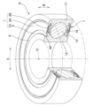
- FIG. 2 is a partially sectional perspective view of a rolling bearing according to an embodiment of the present invention, showing an example in which a first metal plate contacts the outer ring and the inner surface of an annular conductive felt contacts the inner ring.
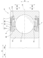
- FIG. 2 is an enlarged longitudinal sectional view of a main portion of the rolling bearing of FIG. 1 .
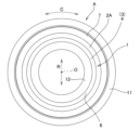
- FIG. 2 is a view of the rolling bearing of FIG. 1 as viewed from the direction of the central axis of rotation.
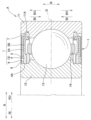
- FIG. 1 is an enlarged longitudinal cross-sectional view of a key portion of a rolling bearing according to an embodiment of the present invention, showing an example in which the inner ring with which the inner surface of the conductive annular felt comes into contact does not have a cylindrical surface as the outer circumferential surface in the width direction, but is an inclined surface that approaches radially outward as it moves inward in the width direction.
- FIG. 1 is a partial cross-sectional oblique view of a rolling bearing according to an embodiment of the present invention, showing an example in which conductive rubber covering the radially outer portions of the first metal plate and the second metal plate and extending radially outward contacts the outer ring, and the inner surface of a conductive annular felt contacts the inner ring.
- FIG. 6 is an enlarged longitudinal sectional view of a main portion of the rolling bearing of FIG. 5 .
- 6 is a view of the rolling bearing of FIG. 5 as viewed from the direction of the central axis of rotation.
- FIG. 6 is a partially sectional perspective view of a rolling bearing according to an embodiment of the present invention, showing an example in which a radially extending rubber piece is attached to an extension of an annular felt, which is a conductive material, in the rolling bearing of FIG.
- FIG. 9 is an enlarged longitudinal sectional view of a main portion of the rolling bearing of FIG. 8 .
- FIG. 9 is a view of the rolling bearing of FIG. 8 as viewed from the direction of the rotation center axis.
- FIG. 6 is a partially sectional perspective view of a rolling bearing according to an embodiment of the present invention, showing an example in which a rubber film is attached to an extension of an annular felt, which is a conductive material, in the rolling bearing of FIG. 5, covering almost the entire surface of the extension.
- FIG. 12 is an enlarged longitudinal sectional view of a main portion of the rolling bearing of FIG. 11 . 12 is a view of the rolling bearing of FIG. 11 as viewed from the direction of the rotation center axis.
- FIG. 6 is a partial sectional oblique view of a rolling bearing according to an embodiment of the present invention, showing an example in which a seal lip is provided inward in the width direction of the rolling bearing of the extension portion of the annular felt, which is a conductive material, and extends away from the extension portion to contact the inner ring.
- FIG. 15 is an enlarged longitudinal sectional view of a main portion of the rolling bearing of FIG. 14 .
- the direction parallel to the direction of the central axis of rotation of the rolling bearing is called the "width direction” (see, for example, arrow B in Figs. 1 and 2)
- the direction perpendicular to the direction of the central axis of rotation is called the "radial direction” (see, for example, arrow R in Figs. 2 and 3).
- the "circumferential direction” is defined with respect to the direction of the central axis of rotation.
- the width direction approaching the widthwise center of the rolling bearing is referred to as the "inward width direction” (e.g., see arrow BI in FIG. 2)
- the width direction moving away from the widthwise center is referred to as the "outward width direction” (e.g., see arrow BO in FIG. 2)
- the radial direction approaching the central axis of rotation is referred to as the "inward radial direction” (e.g., see arrow RI in FIG. 2)
- the radial direction moving away from the central axis of rotation is referred to as the "outward radial direction” (e.g., see arrow RO in FIG. 2).
- Rolling bearings 1 to 15 includes an outer ring 11, an inner ring 12, rolling elements 13, a cage 14, and a bearing seal 1.
- the rolling elements 13 roll between the raceway surface of the outer ring 11 and the raceway surface of the inner ring 12.
- the cage 14 guides the rolling elements 13 at a predetermined interval and holds them rotatably.
- [Bearing seal] 1 to 15 includes annular first and second metal plates 2A and 2B, and a conductive material 3 sandwiched between the first and second metal plates 2A and 2B.
- the conductive material 3 is annular felt 4 having electrical conductivity.
- the annular felt 4 has an extension portion 6 that extends inward RI in the radial direction R from an inner end 5 in the radial direction R of the first and second metal plates 2A and 2B, and an inner circumferential surface 4A of the annular felt 4 contacts an inner ring 12.
- the conductive annular felt 4 is formed by intertwining conductive fibers.
- the conductive fibers are carbon fibers or chemical fibers coated with metal.
- the metals used to coat the chemical fibers are copper, silver, and/or nickel.
- the carbon fibers can also be reinforced by mixing them with polyester resin or polyvinyl chloride resin.
- the first metal plate 2A enters the locking groove 11A of the outer ring 11, and the first metal plate 2A comes into contact with the outer ring 11.
- One or both of the first metal plate 2A and the second metal plate 2B may be brought into contact with the outer ring 11.
- the conductive rubber 7, which covers the outer RO portions of the first metal plate 2A and the second metal plate 2B in the radial direction R and extends outward RO in the radial direction R enters the locking groove 11A of the outer ring 11, and the conductive rubber 7 comes into contact with the outer ring 11.
- the conductive rubber 7 is made of conductive materials such as nitrile rubber (NBR), hydrogenated nitrile rubber (HNBR), acrylic rubber (ACM), silicone rubber (VQM), fluororubber (FKM), and ethylene propylene diene rubber (EPDM).
- NBR nitrile rubber
- HNBR hydrogenated nitrile rubber
- ACM acrylic rubber
- VQM silicone rubber
- FKM fluororubber
- EPDM ethylene propylene diene rubber
- the bearing seal 1 shown in Figures 8 to 10 has rubber pieces 8 extending in the radial direction R attached to the surface of the extension portion 6 of the annular felt 4 on the outer side BO of the width direction B of the rolling bearing A, and the rubber pieces 8 are spaced at approximately equal intervals in the circumferential direction C.
- the bearing seal 1 shown in Figures 11 to 13 has a rubber film 9 attached to the outer surface BO of the extension 6 of the annular felt 4 in the width direction B of the rolling bearing A, covering almost the entire surface.
- the bearing seal 1 shown in Figures 14 and 15 has a seal lip 10 that extends away from the extension 6 of the annular felt 4 on the inner side BI in the width direction B of the rolling bearing A and contacts the inner ring 12.
- the configuration of the bearing seal 1 shown in Figures 14 and 15 provides a seal lip 10 that contacts the inner ring 12, improving the sealing performance of the rolling bearing A. Therefore, this is a suitable embodiment when the rolling bearing A is a grease-filled type.
- the inner peripheral surface 4A of the annular felt 4, which is the conductive material 3 is in contact with the cylindrical surface, which is the outer peripheral surface in the width direction B of the inner ring 12.
- the present invention is not limited to this configuration.
- the inner peripheral surface 4A of the annular felt 4, which is the conductive material 3 may be in contact with the inclined surface of the inner ring 12 which approaches the radially outward RO as it moves inward in the width direction BI.
- the bearing seal 1 shown in Figures 1 to 15 is an inner ring sliding type in which the inner surface 4A of the annular felt 4 slides on the outer surface of the inner ring 12.
- the present invention is not limited to this configuration, and may be an outer ring sliding type.
- the first metal plate 2A and the second metal plate, or the conductive rubber covering the inward RI of the radial direction R of the first metal plate 2A and the second metal plate 2B and extending inward RI of the radial direction R contacts the inner ring 12.
- the annular felt 4 which is the conductive material 3 sandwiched between the first metal plate 2A and the second metal plate 2B, has an extension portion that extends outward RO in the radial direction R from the outer end of the first metal plate 2A and the second metal plate 2B in the radial direction R, and the outer circumferential surface of the annular felt 4 contacts the outer ring 11.
- the seal lip as shown in Figures 14 and 15 extends away from the extension portion and contacts the outer ring 11.
- the conductive material 3 sandwiched between the first metal plate 2A and the second metal plate 2B is the conductive annular felt 4, and the inner circumferential surface 4A or the outer circumferential surface of the annular felt 4 slides on the inner ring 12 or the outer ring 11. Therefore, the annular felt 4, which is a sliding member that slides on the inner ring 12 or the outer ring 11, is conductive no matter where it comes into contact with the inner ring 12 or the outer ring 11, so conductivity can be ensured.
- the conductive material 3 is felt, which is formed by intertwining the conductive fibers themselves. Therefore, no weaving is required, and there are no technical difficulties in manufacturing, making it easy to manufacture, and therefore the manufacturing costs do not increase.
- the extension 6 when the outer surface BO and inner surface BI of the extension 6 of the annular felt 4 in the width direction B of the rolling bearing A are exposed, the extension 6 also functions as a normal felt seal, and has a filtering effect that prevents foreign matter from entering the inside of the bearing in the oil.
Landscapes
- Engineering & Computer Science (AREA)
- General Engineering & Computer Science (AREA)
- Mechanical Engineering (AREA)
- Rolling Contact Bearings (AREA)
- Sealing Of Bearings (AREA)
- Sealing With Elastic Sealing Lips (AREA)
- Sealing Devices (AREA)
Priority Applications (2)
| Application Number | Priority Date | Filing Date | Title |
|---|---|---|---|
| CN202380092439.9A CN120604048A (zh) | 2023-02-17 | 2023-12-06 | 轴承密封件 |
| DE112023005810.5T DE112023005810T5 (de) | 2023-02-17 | 2023-12-06 | Lagerdichtung |
Applications Claiming Priority (2)
| Application Number | Priority Date | Filing Date | Title |
|---|---|---|---|
| JP2023023772A JP2024117596A (ja) | 2023-02-17 | 2023-02-17 | 軸受シール |
| JP2023-023772 | 2023-02-17 |
Publications (1)
| Publication Number | Publication Date |
|---|---|
| WO2024171571A1 true WO2024171571A1 (ja) | 2024-08-22 |
Family
ID=92421182
Family Applications (1)
| Application Number | Title | Priority Date | Filing Date |
|---|---|---|---|
| PCT/JP2023/043672 Ceased WO2024171571A1 (ja) | 2023-02-17 | 2023-12-06 | 軸受シール |
Country Status (4)
| Country | Link |
|---|---|
| JP (1) | JP2024117596A (https=) |
| CN (1) | CN120604048A (https=) |
| DE (1) | DE112023005810T5 (https=) |
| WO (1) | WO2024171571A1 (https=) |
Citations (4)
| Publication number | Priority date | Publication date | Assignee | Title |
|---|---|---|---|---|
| JPS60167263U (ja) * | 1984-04-13 | 1985-11-06 | エヌオーケー株式会社 | オイルシ−ル |
| JP2010106971A (ja) * | 2008-10-30 | 2010-05-13 | Ntn Corp | 転がり軸受 |
| US20190063500A1 (en) * | 2017-08-29 | 2019-02-28 | Schaeffler Technologies AG & Co. KG | Rolling bearing assembly including a crimped sealing assembly having a grounding element |
| US20230013562A1 (en) * | 2019-12-11 | 2023-01-19 | Schaeffler Technologies AG & Co. KG | Discharge device for discharging an electrical charge from a rotor of an electric motor |
-
2023
- 2023-02-17 JP JP2023023772A patent/JP2024117596A/ja active Pending
- 2023-12-06 WO PCT/JP2023/043672 patent/WO2024171571A1/ja not_active Ceased
- 2023-12-06 DE DE112023005810.5T patent/DE112023005810T5/de active Pending
- 2023-12-06 CN CN202380092439.9A patent/CN120604048A/zh active Pending
Patent Citations (4)
| Publication number | Priority date | Publication date | Assignee | Title |
|---|---|---|---|---|
| JPS60167263U (ja) * | 1984-04-13 | 1985-11-06 | エヌオーケー株式会社 | オイルシ−ル |
| JP2010106971A (ja) * | 2008-10-30 | 2010-05-13 | Ntn Corp | 転がり軸受 |
| US20190063500A1 (en) * | 2017-08-29 | 2019-02-28 | Schaeffler Technologies AG & Co. KG | Rolling bearing assembly including a crimped sealing assembly having a grounding element |
| US20230013562A1 (en) * | 2019-12-11 | 2023-01-19 | Schaeffler Technologies AG & Co. KG | Discharge device for discharging an electrical charge from a rotor of an electric motor |
Also Published As
| Publication number | Publication date |
|---|---|
| DE112023005810T5 (de) | 2025-12-18 |
| CN120604048A (zh) | 2025-09-05 |
| JP2024117596A (ja) | 2024-08-29 |
Similar Documents
| Publication | Publication Date | Title |
|---|---|---|
| JP2010106971A (ja) | 転がり軸受 | |
| EP4718963A1 (en) | Electrically conductive structure and electrically conductive sealing device | |
| JP2009079643A (ja) | 通電式転がり軸受 | |
| WO2024171571A1 (ja) | 軸受シール | |
| JP2005114119A (ja) | 通電装置、転がり支持装置 | |
| WO2024171572A1 (ja) | 軸受シール | |
| WO2024171570A1 (ja) | 軸受シール | |
| CN111379788A (zh) | 轴承及密封装置 | |
| JP2025054032A (ja) | 軸受シール | |
| JP2025129656A (ja) | 円環状導電部材 | |
| JP2025054031A (ja) | 軸受シール | |
| WO2025173329A1 (ja) | 軸受シール | |
| JP7694705B2 (ja) | 転がり軸受 | |
| JP7686894B1 (ja) | 導電構造体及び導電密封装置 | |
| US20260039078A1 (en) | Conductive structural body and conduction method | |
| JP7623726B1 (ja) | 密封装置及び軸受装置 | |
| CN223957413U (zh) | 导电油封和电机 | |
| TW202534242A (zh) | 滑環 | |
| WO2023184075A1 (zh) | 导电环 | |
| WO2024262362A1 (ja) | 密封装置 | |
| JP2009156298A (ja) | 転がり軸受 | |
| JP2025070925A (ja) | 転がり軸受用電食防止部材及び電食防止転がり軸受ユニット | |
| JP2025035189A (ja) | 転がり軸受 | |
| JP2026038492A (ja) | 通電ユニットおよび軸受ユニット | |
| WO2025177943A1 (ja) | ロータリコネクタ |
Legal Events
| Date | Code | Title | Description |
|---|---|---|---|
| 121 | Ep: the epo has been informed by wipo that ep was designated in this application |
Ref document number: 23922904 Country of ref document: EP Kind code of ref document: A1 |
|
| WWE | Wipo information: entry into national phase |
Ref document number: 202380092439.9 Country of ref document: CN |
|
| WWP | Wipo information: published in national office |
Ref document number: 202380092439.9 Country of ref document: CN |
|
| WWE | Wipo information: entry into national phase |
Ref document number: 112023005810 Country of ref document: DE |
|
| WWP | Wipo information: published in national office |
Ref document number: 112023005810 Country of ref document: DE |
|
| 122 | Ep: pct application non-entry in european phase |
Ref document number: 23922904 Country of ref document: EP Kind code of ref document: A1 |