WO2024171560A1 - 電池モジュール - Google Patents
電池モジュール Download PDFInfo
- Publication number
- WO2024171560A1 WO2024171560A1 PCT/JP2023/043410 JP2023043410W WO2024171560A1 WO 2024171560 A1 WO2024171560 A1 WO 2024171560A1 JP 2023043410 W JP2023043410 W JP 2023043410W WO 2024171560 A1 WO2024171560 A1 WO 2024171560A1
- Authority
- WO
- WIPO (PCT)
- Prior art keywords
- fuse
- heat
- resistant body
- battery module
- voltage detection
- Prior art date
- Legal status (The legal status is an assumption and is not a legal conclusion. Google has not performed a legal analysis and makes no representation as to the accuracy of the status listed.)
- Ceased
Links
Images


Classifications
-
- H—ELECTRICITY
- H01—ELECTRIC ELEMENTS
- H01M—PROCESSES OR MEANS, e.g. BATTERIES, FOR THE DIRECT CONVERSION OF CHEMICAL ENERGY INTO ELECTRICAL ENERGY
- H01M50/00—Constructional details or processes of manufacture of the non-active parts of electrochemical cells other than fuel cells, e.g. hybrid cells
- H01M50/50—Current conducting connections for cells or batteries
- H01M50/572—Means for preventing undesired use or discharge
- H01M50/574—Devices or arrangements for the interruption of current
- H01M50/583—Devices or arrangements for the interruption of current in response to current, e.g. fuses
-
- H—ELECTRICITY
- H01—ELECTRIC ELEMENTS
- H01M—PROCESSES OR MEANS, e.g. BATTERIES, FOR THE DIRECT CONVERSION OF CHEMICAL ENERGY INTO ELECTRICAL ENERGY
- H01M10/00—Secondary cells; Manufacture thereof
- H01M10/42—Methods or arrangements for servicing or maintenance of secondary cells or secondary half-cells
- H01M10/48—Accumulators combined with arrangements for measuring, testing or indicating the condition of cells, e.g. the level or density of the electrolyte
- H01M10/482—Accumulators combined with arrangements for measuring, testing or indicating the condition of cells, e.g. the level or density of the electrolyte for several batteries or cells simultaneously or sequentially
-
- H—ELECTRICITY
- H01—ELECTRIC ELEMENTS
- H01M—PROCESSES OR MEANS, e.g. BATTERIES, FOR THE DIRECT CONVERSION OF CHEMICAL ENERGY INTO ELECTRICAL ENERGY
- H01M10/00—Secondary cells; Manufacture thereof
- H01M10/60—Heating or cooling; Temperature control
- H01M10/65—Means for temperature control structurally associated with the cells
- H01M10/658—Means for temperature control structurally associated with the cells by thermal insulation or shielding
-
- H—ELECTRICITY
- H01—ELECTRIC ELEMENTS
- H01M—PROCESSES OR MEANS, e.g. BATTERIES, FOR THE DIRECT CONVERSION OF CHEMICAL ENERGY INTO ELECTRICAL ENERGY
- H01M50/00—Constructional details or processes of manufacture of the non-active parts of electrochemical cells other than fuel cells, e.g. hybrid cells
- H01M50/50—Current conducting connections for cells or batteries
- H01M50/569—Constructional details of current conducting connections for detecting conditions inside cells or batteries, e.g. details of voltage sensing terminals
-
- H—ELECTRICITY
- H01—ELECTRIC ELEMENTS
- H01M—PROCESSES OR MEANS, e.g. BATTERIES, FOR THE DIRECT CONVERSION OF CHEMICAL ENERGY INTO ELECTRICAL ENERGY
- H01M2200/00—Safety devices for primary or secondary batteries
- H01M2200/10—Temperature sensitive devices
- H01M2200/103—Fuse
-
- H—ELECTRICITY
- H01—ELECTRIC ELEMENTS
- H01M—PROCESSES OR MEANS, e.g. BATTERIES, FOR THE DIRECT CONVERSION OF CHEMICAL ENERGY INTO ELECTRICAL ENERGY
- H01M50/00—Constructional details or processes of manufacture of the non-active parts of electrochemical cells other than fuel cells, e.g. hybrid cells
- H01M50/20—Mountings; Secondary casings or frames; Racks, modules or packs; Suspension devices; Shock absorbers; Transport or carrying devices; Holders
- H01M50/204—Racks, modules or packs for multiple batteries or multiple cells
-
- Y—GENERAL TAGGING OF NEW TECHNOLOGICAL DEVELOPMENTS; GENERAL TAGGING OF CROSS-SECTIONAL TECHNOLOGIES SPANNING OVER SEVERAL SECTIONS OF THE IPC; TECHNICAL SUBJECTS COVERED BY FORMER USPC CROSS-REFERENCE ART COLLECTIONS [XRACs] AND DIGESTS
- Y02—TECHNOLOGIES OR APPLICATIONS FOR MITIGATION OR ADAPTATION AGAINST CLIMATE CHANGE
- Y02E—REDUCTION OF GREENHOUSE GAS [GHG] EMISSIONS, RELATED TO ENERGY GENERATION, TRANSMISSION OR DISTRIBUTION
- Y02E60/00—Enabling technologies; Technologies with a potential or indirect contribution to GHG emissions mitigation
- Y02E60/10—Energy storage using batteries
Definitions
- the present invention relates to a battery module.
- a battery module includes a plurality of battery cells stacked in a predetermined direction, and a bus bar electrically connected to the plurality of battery cells.
- the bus bar has a fuse portion.
- This battery module further includes an insulation cover that surrounds the periphery of the bus bar, and a module cover fixed to the upper part of the insulation cover.
- a fuse may be electrically connected to a battery cell. If the fuse melts, the fuse may not only fall below the fuse, but may also scatter around the fuse. However, if the fuse scatters around the fuse, it may be difficult to suppress the effects on the components around the fuse.
- One object of the present invention is to suppress the impact of a fuse scattering on the components surrounding the fuse. Other objects of the present invention will become apparent from the description of this specification.
- a battery cell a fuse electrically connected to the battery cell and extending in a predetermined direction; a heat-resistant body at least partially surrounding the fuse around the predetermined direction;
- a battery module comprising: [2] A voltage detection unit electrically connected to the battery cell; A holder that holds the voltage detection unit; Further equipped with The battery module according to [1], wherein at least a portion of the heat-resistant body is provided on the holder.
- the battery pack further includes a housing for housing the battery cell.
- the above aspect of the present invention makes it possible to suppress the impact of the fuse scattering on the components surrounding the fuse.
- FIG. 2 is a perspective view of a battery module according to the embodiment.
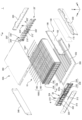
- FIG. 2 is an exploded perspective view of the battery module according to the embodiment.
- FIG. 2 is an exploded enlarged perspective view of a right front portion of the battery module according to the embodiment. 2 is a cross-sectional view taken along line AA of FIG. 1.
- FIG. 5 is a diagram showing a modification of FIG. 4 .
- FIG. 1 is a perspective view of a battery module 1 according to an embodiment.
- FIG. 2 is an exploded perspective view of a battery module 1 according to an embodiment.
- FIG. 3 is an exploded enlarged perspective view of the right front portion of a battery module 1 according to an embodiment.
- arrows indicating the X, Y, and Z directions are shown for the purpose of explanation.
- the tip of the arrow indicating the X direction is the rear side of the battery module 1
- the base end of the arrow indicating the X direction is the front side of the battery module 1.
- the Y direction is perpendicular to the X direction.
- the Y direction is the left-right direction of the battery module 1.
- the tip of the arrow indicating the Y direction is the left side of the battery module 1
- the base end of the arrow indicating the Y direction is the right side of the battery module 1.
- the Z direction is perpendicular to both the X and Y directions.
- the Z direction is the up-down direction of the battery module 1.
- the tip of the arrow indicating the Z direction is the upper side of the battery module 1, and the base end of the arrow indicating the Z direction is the lower side of the battery module 1.
- the direction perpendicular to the X direction is referred to as the YZ plane direction
- the direction perpendicular to the Y direction is referred to as the ZX plane direction
- the direction perpendicular to the Z direction is referred to as the XY plane direction.
- the relationship between the X, Y, and Z directions and the front-rear, left-right, and up-down directions of the battery module 1 is not limited to the above example.
- the battery module 1 comprises a cell stack 10, a front voltage detection device 20, a rear voltage detection device 20', and a housing 30.
- the cell stack 10 has a plurality of battery cells 100 and a plurality of compression pads 110.
- the plurality of battery cells 100 and the plurality of compression pads 110 are arranged alternately in the Y direction. Compression pads 110 are arranged on both sides of each battery cell 100 in the Y direction.
- the plurality of battery cells 100 and the plurality of compression pads 110 are compressed in the Y direction by a right plate 330 and a left plate 340, which will be described later. Therefore, it is possible to suppress deviation of the battery cells 100 in the ZX plane direction.
- each battery cell 100 is approximately parallel to the X direction.
- the lateral direction of each battery cell 100 is approximately parallel to the Z direction.
- the thickness direction of each battery cell 100 is approximately parallel to the Y direction.
- the multiple battery cells 100 are stacked in the Y direction. Note that the shape of each battery cell 100 is not limited to this example.
- Each battery cell 100 includes a battery element (not shown), an exterior material 102, a positive electrode tab 104, and a negative electrode tab 106.
- the battery element includes a plurality of positive electrodes and a plurality of negative electrodes (not shown) stacked alternately in the Y direction, and a separator (not shown) located between adjacent positive electrodes and negative electrodes in the Y direction.
- the exterior material 102 seals the battery element and an electrolyte (not shown).
- the positive electrode tab 104 is electrically connected to the positive electrode of the battery element.
- the positive electrode tab 104 is pulled out from one of both sides of the exterior material 102 in the X direction.
- the negative electrode tab 106 is electrically connected to the negative electrode of the battery element.
- the negative electrode tab 106 is pulled out from the other side of both sides of the exterior material 102 in the X direction.
- the structure of each battery cell 100 is not limited to this example.
- a plurality of cell groups 100G are connected in series from a cell group 100G located at one end in the Y direction to a cell group 100G located at the other end in the Y direction.
- Each cell group 100G includes a plurality of battery cells 100 connected in parallel.
- each cell group 100G includes two battery cells 100 adjacent in the Y direction.
- Two positive electrode tabs 104 drawn out from the two battery cells 100 included in each cell group 100G are oriented to the same side in the X direction.
- Two negative electrode tabs 106 drawn out from the two battery cells 100 included in each cell group 100G are oriented to the same side in the X direction.
- the positive electrode tab 104 and the negative electrode tab 106 drawn out from one of the cell groups 100G adjacent in the Y direction and the positive electrode tab 104 and the negative electrode tab 106 drawn out from the other cell group 100G adjacent in the Y direction are oriented in opposite directions in the X direction.
- Two cell groups 100G adjacent to each other in the Y direction include tab groups 108 located in front or behind the two cell groups 100G.
- the tab groups 108 include positive electrode tabs 104 and negative electrode tabs 106 that are joined to each other.
- the positive electrode tabs 104 and negative electrode tabs 106 included in the tab groups 108 are joined to each other by, for example, laser welding. Therefore, the multiple tab groups 108 located in front of the cell stack 10 and the multiple tab groups 108 located in the rear of the cell stack 10 are arranged alternately.
- positive electrode tabs 104 are pulled out toward the front from the two battery cells 100 located at the right end of the cell stack 10.
- these positive electrode tabs 104 are referred to as terminal positive electrode tabs 104T.
- the number of terminal positive electrode tabs 104T may be only one, or may be three or more.
- negative electrode tabs 106 are pulled out toward the rear from the two battery cells 100 located at the left end of the cell stack 10.
- these negative electrode tabs 106 are referred to as terminal negative electrode tabs 106T.
- the number of terminal negative electrode tabs 106T may be only one, or may be three or more.
- each cell group 100G may include three or more battery cells 100 connected in parallel.
- a single battery cell 100 may be connected in series from a battery cell 100 located at one end in the Y direction to a battery cell 100 located at the other end in the Y direction.
- the positions at which the terminal positive electrode tab 104T and the terminal negative electrode tab 106T are arranged are not limited to the above example.
- the positions of the terminal positive electrode tab 104T and the terminal negative electrode tab 106T change depending on the number of cell groups 100G. For example, depending on the number of cell groups 100G, both the terminal positive electrode tab 104T and the terminal negative electrode tab 106T are arranged in the front or rear of the cell stack 10.
- the forward voltage detection device 20 has a forward holder 210, a plurality of forward voltage detection units 220, a plurality of forward voltage detection lines 222, a forward connector 224, and a positive bus bar 230.
- the front holder 210 is disposed in front of the cell stack 10.
- the front holder 210 defines a number of front openings 212.
- Each of the multiple tab groups 108 located in front of the cell stack 10 is exposed forward through each of the multiple front openings 212.
- the front holder 210 integrally holds a number of front voltage detection sections 220 and a number of front voltage detection lines 222.
- the multiple forward voltage detectors 220 are attached to the front holder 210. Each of the multiple forward voltage detectors 220 is joined to the front surface of each of the multiple tab groups 108 located in front of the cell stack 10, for example by laser welding.
- the multiple forward voltage detectors 220 are electrically connected to the front connector 224 via multiple forward voltage detection wires 222.
- the multiple forward voltage detection wires 222 are routed through the front holder 210. In the embodiment, by installing the front holder 210 at an appropriate position relative to the cell stack 10, each of the multiple forward voltage detectors 220 can be positioned at an appropriate position relative to each of the multiple tab groups 108 located in front of the cell stack 10.
- the positive busbar 230 is disposed at the right end of the front retainer 210.
- the positive busbar 230 is generally L-shaped.
- the positive busbar 230 includes a front horizontal conductor 232 and a front vertical conductor 234.
- the front horizontal conductor 232 extends generally parallel to the Y direction.
- the front vertical conductor 234 extends downward from the right end of the front horizontal conductor 232 generally parallel to the Z direction.
- the front horizontal conductor 232 functions as a terminal for electrically connecting to an external device such as another battery module.
- a fastening hole 232a is provided at the left end of the front horizontal conductor 232.
- a fastening device (not shown) can be installed in the fastening hole 232a for fastening a bus bar (not shown) that is electrically connected to an external device (not shown) such as another battery module.
- the front horizontal conductor 232 includes a fuse 233.
- the fuse 233 is located to the right of the fastening hole 232a.
- the fuse 233 extends approximately parallel to the Y direction.
- the front horizontal conductor 232 has a notch at the rear of the fuse 233. Therefore, the cross section of the fuse 233 perpendicular to the Y direction is smaller than the cross sections perpendicular to the Y direction of both sides of the fuse 233 in the front horizontal conductor 232. Therefore, when a current of a predetermined value or more flows through the fuse 233, the fuse 233 can melt.
- the structure of the fuse 233 is not limited to this example.
- the fuse 233 may be defined by a notch provided in front of the front horizontal conductor 232.
- the fuse 233 may be defined by notches provided both in front and behind the front horizontal conductor 232.
- the fuse 233 is located, for example, approximately in the center of the front horizontal conductor 232 in the X direction.
- the fuse 233 may be offset in the X direction from approximately the center of the front horizontal conductor 232 in the X direction.
- the thickness of the front horizontal conductor 232 in the Z direction may be partially thinned. In this case, the fuse 233 is a part of the front horizontal conductor 232 that is partially thin in the Z direction.
- the front vertical conductor 234 is electrically connected to the terminal positive electrode tab 104T.
- the terminal positive electrode tab 104T is located to the right of the front vertical conductor 234.
- the terminal positive electrode tab 104T and the front vertical conductor 234 are joined by laser welding.
- the method of joining the terminal positive electrode tab 104T and the front vertical conductor 234 is not limited to laser welding.
- the rear voltage detection device 20' is similar to the front voltage detection device 20, except for the following points.
- the rear voltage detection device 20' has a rear holder 210', a plurality of rear voltage detection parts 220', a plurality of rear voltage detection lines 222', a rear connector 224', and a negative bus bar 230'.
- the rear retainer 210' is disposed at the rear of the cell stack 10.
- the rear retainer 210' defines a number of rear openings 212'.
- Each of the multiple tab groups 108 located at the rear of the cell stack 10 is exposed toward the rear through each of the multiple rear openings 212'.
- the rear retainer 210' integrally holds the multiple rear voltage detection sections 220' and the multiple rear voltage detection lines 222'.
- the multiple rear voltage detectors 220' are attached to the rear holder 210'. Each of the multiple rear voltage detectors 220' is joined to the rear surface of each of the multiple tab groups 108 located at the rear of the cell stack 10, for example by laser welding.
- the multiple rear voltage detectors 220' are electrically connected to the rear connector 224' via multiple rear voltage detection wires 222'.
- the multiple rear voltage detection wires 222' are routed through the rear holder 210'. In the embodiment, by installing the rear holder 210' at an appropriate position relative to the cell stack 10, each of the multiple rear voltage detectors 220' can be positioned at an appropriate position relative to each of the multiple tab groups 108 located at the rear of the cell stack 10.
- the negative busbar 230' is disposed at the left end of the rear retainer 210'.
- the negative busbar 230' is generally L-shaped.
- the negative busbar 230' includes a rear horizontal conductor 232' and a rear vertical conductor 234'.
- the rear horizontal conductor 232' extends generally parallel to the Y direction.
- the rear vertical conductor 234' extends downward from the left end of the rear horizontal conductor 232' generally parallel to the Z direction.
- the rear horizontal conductor 232' functions as a terminal for electrically connecting to an external device such as another battery module. Like the front horizontal conductor 232, the rear horizontal conductor 232' has a fuse.
- the rear vertical conductor 234' is electrically connected to the terminating negative electrode tab 106T.
- the terminating negative electrode tab 106T is located to the left of the rear vertical conductor 234'.
- the terminating negative electrode tab 106T and the rear vertical conductor 234' are joined by laser welding.
- the method of joining the terminating negative electrode tab 106T and the rear vertical conductor 234' is not limited to laser welding.
- the housing 30 has a front plate 310, a rear plate 320, a right plate 330, a left plate 340, a lower plate 350, and an upper plate 360. As described later with reference to FIG. 4, the housing 30 further has a coated heat-resistant body 311.
- the front plate 310 covers the cell stack 10 and the front voltage detection device 20 from the front.
- the front plate 310 is, for example, a metal plate such as an aluminum plate.
- the rear plate 320 covers the cell stack 10 and the rear voltage detection device 20' from the rear.
- the rear plate 320 is, for example, a metal plate such as an aluminum plate.
- the right plate 330 covers the cell stack 10, the front voltage detection device 20, and the rear voltage detection device 20' from the right side.
- the right plate 330 is made of a conductive material such as metal.
- the left plate 340 covers the cell stack 10, the front voltage detection device 20, and the rear voltage detection device 20' from the left.
- the left plate 340 is made of a conductive material such as metal.
- the lower plate 350 covers the cell stack 10, the front voltage detection device 20, and the rear voltage detection device 20' from below.
- the lower plate 350 is made of a conductive material such as metal.
- a thermally conductive adhesive 352 is disposed between the upper surface of the lower plate 350 and the lower end of the cell stack 10. This allows heat generated from the cell stack 10 to escape through the thermally conductive adhesive 352 toward the bottom of the battery module 1.
- the upper plate 360 covers the cell stack 10, the front voltage detection device 20, and the rear voltage detection device 20' from above.
- the upper plate 360 is made of a conductive material such as metal.
- Figure 4 is a cross-sectional view taken along the line A-A in Figure 1.
- the white circle with an X indicating the Y direction indicates that the direction from the base end of the arrow indicating the Y direction is the direction from the front to the back of the page.
- the front holder 210 is provided with a surrounding heat-resistant body 211.
- the surrounding heat-resistant body 211 contains a heat-resistant material such as a heat-resistant resin.
- heat-resistant materials include polypropylene (PP), polybutylene terephthalate (PBT), modified polyphenylene ether, silicone-based resin, and silica fiber.
- the surrounding heat-resistant body 211 may contain a single heat-resistant material exemplified here, or may contain multiple types of heat-resistant materials exemplified here.
- the melting point of the heat-resistant material is, for example, 150°C or higher, preferably 200°C or higher.
- the surrounding heat-resistant body 211 surrounds at least a portion of the fuse 233 in the Y direction. Specifically, in the example shown in FIG. 4, the surrounding heat-resistant body 211 surrounds the fuse 233 in the Y direction, except for the front of the fuse 233. In other words, the surrounding heat-resistant body 211 is open toward the front. Therefore, when viewed from the Y direction, the surrounding heat-resistant body 211 is approximately U-shaped or approximately n-shaped.
- the surrounding heat-resistant body 211 is spaced apart from the fuse 233 all around the fuse 233 in the Y direction. Therefore, when viewed from the Y direction, a gap exists between the fuse 233 and the surrounding heat-resistant body 211, except for the front of the fuse 233. Therefore, when the fuse 233 melts, the fuse 233 can fall toward the gap below the fuse 233. Therefore, compared to when the fuse 233 and the surrounding heat-resistant body 211 are in contact with each other, the fuse 233 can be more easily broken by melting the fuse 233.
- the surrounding heat-resistant body 211 may be in at least partial contact with the fuse 233, except for the bottom surface of the fuse 233.
- a protrusion 310a is provided on the rear surface of the upper end of the front plate 310.
- the protrusion 310a protrudes rearward from the rear surface of the upper end of the front plate 310.
- the contact area between the upper surface of the upper end of the front plate 310 and the lower surface of the front end of the upper plate 360 can be made larger than when the protrusion 310a is not provided. Therefore, when the protrusion 310a is provided, the upper surface of the upper end of the front plate 310 and the lower surface of the front end of the upper plate 360 can be more easily joined by a joining method such as welding than when the protrusion 310a is not provided.
- the coated heat-resistant body 311 is provided on the rear surface of the front plate 310.
- the coated heat-resistant body 311 contains a heat-resistant material such as a heat-resistant resin.
- Examples of the heat-resistant material of the coated heat-resistant body 311 include the materials exemplified for the surrounding heat-resistant body 211.
- the heat-resistant material forming the coated heat-resistant body 311 and the heat-resistant material forming the surrounding heat-resistant body 211 may be different or the same.
- the coated heat-resistant body 311 is attached to the rear surface of the front plate 310.
- the coated heat-resistant body 311 may be formed on the rear surface of the front plate 310 by a deposition method such as vapor deposition.
- the coated heat-resistant body 311 covers at least a portion of the rear surface of the front plate 310.
- the upper end of the coated heat-resistant body 311 is located in front of the fuse 233.
- the surrounding heat-resistant body 211 and the coated heat-resistant body 311 together surround at least a portion of the fuse 233 around the Y direction. This makes it possible to suppress the impact of the fuse 233 scattering on the components surrounding the fuse 233.
- the coated heat-resistant body 311 exposes the underside of the protrusion 310a. This makes it easier to install the coated heat-resistant body 311 on the rear surface of the front plate 310 compared to when the coated heat-resistant body 311 covers the underside of the protrusion 310a.
- the distance of the gap between the fuse 233 and the protrusion 310a can be set to a distance that prevents the scattering of the fuse 233 from reaching the protrusion 310a. In this example, even if at least a portion of the protrusion 310a is exposed from the coated heat-resistant body 311, the impact of scattering of the fuse 233 on the protrusion 310a can be suppressed.
- the surrounding heat-resistant body 211 is provided on the front holder 210. Therefore, the number of parts of the battery module 1 can be reduced compared to when a member different from the front holder 210 is provided to provide the surrounding heat-resistant body 211.
- the coated heat-resistant body 311 is provided on the front plate 310. Therefore, the number of parts of the battery module 1 can be reduced compared to when a member different from the front plate 310 is provided to provide the coated heat-resistant body 311.
- the method of at least partially surrounding the fuse 233 in the Y direction with a heat-resistant material is not limited to the method described in the embodiment.
- the coated heat-resistant body 311 may not be provided.
- a portion of the surrounding heat-resistant body 211 may be located in front of the fuse 233.
- the front plate 310 itself may be heat-resistant.
- the gap distance between the fuse 233 and the rear surface of the front plate 310 may be a distance that prevents flying debris from reaching the rear surface of the front plate 310.
- a heat-resistant body may not be provided in front of the fuse 233.
- a heat-resistant body has been described around the fuse 233 of the positive bus bar 230.
- a heat-resistant body similar to the heat-resistant body described in the embodiment can also be provided around a fuse other than the fuse 233 of the positive bus bar 230.
- a heat-resistant body may also be provided around the fuse of the negative bus bar 230'.
- FIG. 5 shows a modified example of FIG. 4.
- the upper end of the coated heat-resistant body 311A when viewed from the Y direction, is bent toward the rear at approximately a right angle. In other words, when viewed from the Y direction, the upper end of the coated heat-resistant body 311A is approximately L-shaped. Therefore, the upper end of the coated heat-resistant body 311A covers the lower surface of the protrusion 310a. Therefore, it is easier to protect the protrusion 310a from flying debris from the fuse 233 compared to when the upper end of the coated heat-resistant body 311A does not cover the lower surface of the protrusion 310a.
Landscapes
- Chemical & Material Sciences (AREA)
- Chemical Kinetics & Catalysis (AREA)
- Electrochemistry (AREA)
- General Chemical & Material Sciences (AREA)
- Engineering & Computer Science (AREA)
- Manufacturing & Machinery (AREA)
- Connection Of Batteries Or Terminals (AREA)
- Battery Mounting, Suspending (AREA)
Priority Applications (2)
| Application Number | Priority Date | Filing Date | Title |
|---|---|---|---|
| CN202380093894.0A CN120604387A (zh) | 2023-02-15 | 2023-12-05 | 电池模块 |
| EP23922893.5A EP4668429A1 (en) | 2023-02-15 | 2023-12-05 | Battery module |
Applications Claiming Priority (2)
| Application Number | Priority Date | Filing Date | Title |
|---|---|---|---|
| JP2023-021503 | 2023-02-15 | ||
| JP2023021503A JP2024115711A (ja) | 2023-02-15 | 2023-02-15 | 電池モジュール |
Publications (1)
| Publication Number | Publication Date |
|---|---|
| WO2024171560A1 true WO2024171560A1 (ja) | 2024-08-22 |
Family
ID=92421212
Family Applications (1)
| Application Number | Title | Priority Date | Filing Date |
|---|---|---|---|
| PCT/JP2023/043410 Ceased WO2024171560A1 (ja) | 2023-02-15 | 2023-12-05 | 電池モジュール |
Country Status (4)
| Country | Link |
|---|---|
| EP (1) | EP4668429A1 (https=) |
| JP (1) | JP2024115711A (https=) |
| CN (1) | CN120604387A (https=) |
| WO (1) | WO2024171560A1 (https=) |
Citations (11)
| Publication number | Priority date | Publication date | Assignee | Title |
|---|---|---|---|---|
| JP2009158219A (ja) * | 2007-12-26 | 2009-07-16 | Toyota Motor Corp | 車載用蓄電装置 |
| JP2014527688A (ja) * | 2011-08-01 | 2014-10-16 | エルジー・ケム・リミテッド | 安全性の向上した電池モジュール |
| JP2016115616A (ja) * | 2014-12-17 | 2016-06-23 | 株式会社オートネットワーク技術研究所 | 検知モジュール |
| KR20170095075A (ko) * | 2016-02-12 | 2017-08-22 | 주식회사 엘지화학 | 배터리 팩 및 이러한 배터리 팩을 포함하는 자동차 |
| JP2018097987A (ja) * | 2016-12-09 | 2018-06-21 | 矢崎総業株式会社 | 導体の接続構造および導電モジュール |
| WO2019069837A1 (ja) | 2017-10-05 | 2019-04-11 | 日立オートモティブシステムズ株式会社 | 電池モジュール |
| JP2021518984A (ja) * | 2018-12-26 | 2021-08-05 | エルジー・ケム・リミテッド | バッテリーモジュール、該バッテリーモジュールを含むバッテリーパック及び該バッテリーパックを含む自動車 |
| WO2022039394A1 (ko) * | 2020-08-21 | 2022-02-24 | 주식회사 엘지에너지솔루션 | 리무버블 퓨즈 어셈블리를 구비한 배터리 모듈 및 이를 포함하는 배터리 팩 |
| US20220200102A1 (en) * | 2020-12-23 | 2022-06-23 | Hyundai Mobis Co., Ltd. | Fusing bus bar for battery module transportation and insulating case comprising same |
| JP2023021503A (ja) | 2021-08-02 | 2023-02-14 | 株式会社ナカヨ | 非改竄通話録音機能を有する電話機、プログラム |
| JP2023050127A (ja) * | 2021-09-29 | 2023-04-10 | 株式会社エンビジョンAescジャパン | 電池モジュール |
-
2023
- 2023-02-15 JP JP2023021503A patent/JP2024115711A/ja active Pending
- 2023-12-05 WO PCT/JP2023/043410 patent/WO2024171560A1/ja not_active Ceased
- 2023-12-05 EP EP23922893.5A patent/EP4668429A1/en active Pending
- 2023-12-05 CN CN202380093894.0A patent/CN120604387A/zh active Pending
Patent Citations (11)
| Publication number | Priority date | Publication date | Assignee | Title |
|---|---|---|---|---|
| JP2009158219A (ja) * | 2007-12-26 | 2009-07-16 | Toyota Motor Corp | 車載用蓄電装置 |
| JP2014527688A (ja) * | 2011-08-01 | 2014-10-16 | エルジー・ケム・リミテッド | 安全性の向上した電池モジュール |
| JP2016115616A (ja) * | 2014-12-17 | 2016-06-23 | 株式会社オートネットワーク技術研究所 | 検知モジュール |
| KR20170095075A (ko) * | 2016-02-12 | 2017-08-22 | 주식회사 엘지화학 | 배터리 팩 및 이러한 배터리 팩을 포함하는 자동차 |
| JP2018097987A (ja) * | 2016-12-09 | 2018-06-21 | 矢崎総業株式会社 | 導体の接続構造および導電モジュール |
| WO2019069837A1 (ja) | 2017-10-05 | 2019-04-11 | 日立オートモティブシステムズ株式会社 | 電池モジュール |
| JP2021518984A (ja) * | 2018-12-26 | 2021-08-05 | エルジー・ケム・リミテッド | バッテリーモジュール、該バッテリーモジュールを含むバッテリーパック及び該バッテリーパックを含む自動車 |
| WO2022039394A1 (ko) * | 2020-08-21 | 2022-02-24 | 주식회사 엘지에너지솔루션 | 리무버블 퓨즈 어셈블리를 구비한 배터리 모듈 및 이를 포함하는 배터리 팩 |
| US20220200102A1 (en) * | 2020-12-23 | 2022-06-23 | Hyundai Mobis Co., Ltd. | Fusing bus bar for battery module transportation and insulating case comprising same |
| JP2023021503A (ja) | 2021-08-02 | 2023-02-14 | 株式会社ナカヨ | 非改竄通話録音機能を有する電話機、プログラム |
| JP2023050127A (ja) * | 2021-09-29 | 2023-04-10 | 株式会社エンビジョンAescジャパン | 電池モジュール |
Non-Patent Citations (1)
| Title |
|---|
| See also references of EP4668429A1 |
Also Published As
| Publication number | Publication date |
|---|---|
| JP2024115711A (ja) | 2024-08-27 |
| EP4668429A1 (en) | 2025-12-24 |
| CN120604387A (zh) | 2025-09-05 |
Similar Documents
| Publication | Publication Date | Title |
|---|---|---|
| US10819049B2 (en) | Welded structure | |
| CN114335923A (zh) | 接线端子保护盖及包括该接线端子保护盖的电池模块 | |
| CN112103454A (zh) | 电线保持结构和汇流条模块 | |
| JP7596336B2 (ja) | 電池モジュール | |
| WO2024171560A1 (ja) | 電池モジュール | |
| JP2024115711A5 (https=) | ||
| JP7667720B2 (ja) | ヒューズ装置及び電池モジュール | |
| JP7690413B2 (ja) | 電圧検出装置及び電池モジュール | |
| JP7588108B2 (ja) | 電圧検出装置及び電池モジュール | |
| JP2024077195A (ja) | ヒューズ装置及び電池モジュール | |
| JP7691331B2 (ja) | 電圧検出装置及び電池モジュール | |
| JP7672941B2 (ja) | 電圧検出装置及び電池モジュール | |
| JP2025130923A (ja) | 電圧検出装置及び電池モジュール | |
| WO2025182675A1 (ja) | 電圧検出装置及び電池モジュール | |
| WO2024202251A1 (ja) | 温度センサ装置、電圧検出装置及び電池モジュール | |
| EP4672294A1 (en) | FUSE DEVICE AND BATTERY MODULE | |
| EP4726878A1 (en) | Battery pack | |
| CN120530525A (zh) | 电池模块 | |
| WO2025211328A1 (ja) | 電池モジュール | |
| JP2025166354A (ja) | 電池モジュール | |
| CN121942095A (zh) | 电池模块 | |
| WO2025074833A1 (ja) | 電池モジュール |
Legal Events
| Date | Code | Title | Description |
|---|---|---|---|
| 121 | Ep: the epo has been informed by wipo that ep was designated in this application |
Ref document number: 23922893 Country of ref document: EP Kind code of ref document: A1 |
|
| WWE | Wipo information: entry into national phase |
Ref document number: 202380093894.0 Country of ref document: CN |
|
| WWP | Wipo information: published in national office |
Ref document number: 202380093894.0 Country of ref document: CN |
|
| WWE | Wipo information: entry into national phase |
Ref document number: 2023922893 Country of ref document: EP |
|
| NENP | Non-entry into the national phase |
Ref country code: DE |
|
| ENP | Entry into the national phase |
Ref document number: 2023922893 Country of ref document: EP Effective date: 20250915 |
|
| WWP | Wipo information: published in national office |
Ref document number: 2023922893 Country of ref document: EP |