WO2024171425A1 - 射出成形機のスクリュヘッド - Google Patents
射出成形機のスクリュヘッド Download PDFInfo
- Publication number
- WO2024171425A1 WO2024171425A1 PCT/JP2023/005655 JP2023005655W WO2024171425A1 WO 2024171425 A1 WO2024171425 A1 WO 2024171425A1 JP 2023005655 W JP2023005655 W JP 2023005655W WO 2024171425 A1 WO2024171425 A1 WO 2024171425A1
- Authority
- WO
- WIPO (PCT)
- Prior art keywords
- screw
- screw head
- transition
- tapered
- injection molding
- Prior art date
- Legal status (The legal status is an assumption and is not a legal conclusion. Google has not performed a legal analysis and makes no representation as to the accuracy of the status listed.)
- Ceased
Links
Images





Classifications
-
- B—PERFORMING OPERATIONS; TRANSPORTING
- B29—WORKING OF PLASTICS; WORKING OF SUBSTANCES IN A PLASTIC STATE IN GENERAL
- B29C—SHAPING OR JOINING OF PLASTICS; SHAPING OF MATERIAL IN A PLASTIC STATE, NOT OTHERWISE PROVIDED FOR; AFTER-TREATMENT OF THE SHAPED PRODUCTS, e.g. REPAIRING
- B29C45/00—Injection moulding, i.e. forcing the required volume of moulding material through a nozzle into a closed mould; Apparatus therefor
- B29C45/17—Component parts, details or accessories; Auxiliary operations
- B29C45/46—Means for plasticising or homogenising the moulding material or forcing it into the mould
- B29C45/58—Details
- B29C45/60—Screws
-
- B—PERFORMING OPERATIONS; TRANSPORTING
- B29—WORKING OF PLASTICS; WORKING OF SUBSTANCES IN A PLASTIC STATE IN GENERAL
- B29C—SHAPING OR JOINING OF PLASTICS; SHAPING OF MATERIAL IN A PLASTIC STATE, NOT OTHERWISE PROVIDED FOR; AFTER-TREATMENT OF THE SHAPED PRODUCTS, e.g. REPAIRING
- B29C45/00—Injection moulding, i.e. forcing the required volume of moulding material through a nozzle into a closed mould; Apparatus therefor
- B29C45/17—Component parts, details or accessories; Auxiliary operations
- B29C45/46—Means for plasticising or homogenising the moulding material or forcing it into the mould
- B29C45/47—Means for plasticising or homogenising the moulding material or forcing it into the mould using screws
- B29C45/50—Axially movable screw
Definitions
- This disclosure relates to a screw head for an injection molding machine.
- a screw head is conventionally fastened to the tip of the screw for an injection molding machine to prevent the backflow of resin.
- the screw head is repeatedly subjected to pressure during injection, torsional torque during metering, and tensile force during suck-back throughout the molding cycle.
- the stress amplitude caused by these repeated external forces can cause fatigue failure of the threaded portion of the screw head.
- a constriction with a diameter smaller than the thread root diameter is sometimes provided (see, for example, Patent Document 1).
- the rigidity of the lower part of the screw neck is intentionally reduced. This reduces the proportion of force that the screw head bears (internal/external force ratio) when an external tensile/compressive force is applied, and the stress amplitude can be reduced.
- the necked portion has a small diameter due to its configuration, it is vulnerable to the torsional torque applied during measurement. If the resin is not sufficiently molten, excessive torsional torque may result in static destruction. For this reason, it is necessary to strike a balance between the fatigue strength of the threaded portion against external tensile and compressive forces and the static strength of the necked portion against torsional torque.
- This disclosure has been made in consideration of the above problems, and aims to provide technology that can achieve an appropriate balance between the fatigue strength of the threaded portion and the static strength of the neck portion in the screw head of an injection molding machine.
- the present disclosure relates to a screw head for an injection molding machine that is attached to the tip of a screw for use in an injection molding machine, and in a lower neck portion located on the screw side relative to an upper neck portion located on the tip side of the screw head, a male thread portion that screws into the screw, and a constricted portion located on the tip side of the male thread portion and having a smaller diameter than the root diameter of the male thread portion are arranged, and the male thread portion has a first tapered portion located on the constricted portion side and having a decreasing outer diameter as it advances toward the constricted portion, a transition portion located on the screw side of the first tapered portion, and a second tapered portion adjacent to the first tapered portion across the transition portion and having a decreasing outer diameter as it advances toward the constricted portion, and the first tapered portion is formed to have a greater average gradient than the second tapered portion.
- This disclosure provides technology that can achieve an appropriate balance between the fatigue strength of the threaded portion and the static strength of the neck portion in the screw head of an injection molding machine.
- FIG. 1 is a schematic diagram showing an example of a configuration of an injection molding machine to which a screw head according to a first embodiment is applied.
- FIG. FIG. 2 is a side view of the screw head of the first embodiment.
- FIG. 2 is an enlarged side view of a male thread portion of the screw head of the first embodiment.
- FIG. 2 is a side view showing the shape of the screw head of Comparative Example 1.
- FIG. 2 is a side view showing the shape of a screw head in the embodiment.
- FIG. 11 is a side view showing the shape of the screw head of Comparative Example 2.
- 1 is a graph showing a difference in equivalent stress between a comparative example and an embodiment.
- FIG. 11 is a side view showing a screw head and an internal thread portion of a screw according to a second embodiment.
- FIG. 11 is a side view of the screw head of the third embodiment.
- FIG. 10 is a side view of the screw head of the fourth embodiment.
- FIG. 13 is a side view of the screw
- FIG. 1 is a schematic diagram showing an example of the configuration of an injection molding machine 1 according to a first embodiment.
- the injection molding machine 1 of this embodiment includes an injection section 2 and a mold clamping section 3.
- the injection unit 2 is an injection device that includes a hopper 21, a cylinder 22, and a screw 23.
- the cylinder 22 is, for example, a cylindrical body. Resin stored in the hopper 21 is supplied to the cylinder 22.
- the screw 23 is disposed inside the cylinder 22, and transports the resin to the tip of the cylinder 22 by rotation.
- a screw head 30 is disposed at the tip of the screw 23.
- a check ring (not shown) abuts against the screw head 30, forming a flow path through which the resin flows forward.
- the check ring abuts against a seat ring (not shown) to close the flow path and prevent backflow.
- the configuration of the screw head 30 will be described in detail later.
- a heater (not shown) is disposed in the cylinder 22 to heat the pellets in order to melt them.
- the melted pellets are transported to the tip side by the screw 23 and injected into the die 5.
- the mold clamping unit 3 is a device that clamps the mold 5. A molded product is formed by clamping the mold 5 with the mold clamping unit 3.
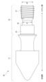
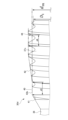
- Figure 2 is a side view of the screw head 30 of the first embodiment.
- the screw head 30 of this embodiment includes an upper neck portion 31 that is on the tip side of the screw head 30 in the axial direction, and a lower neck portion 32 that is on the screw 23 side in the axial direction.
- the neck portion 31 is the part that comes into contact with the molten resin, and together with the other tip parts, forms a flow path for the molten resin.
- the neck portion 32 includes a centering portion 35, a constricted portion 36, and a male thread portion 37.
- the centering portion 35 is a portion that adjusts the axial direction of the screw 23 to coincide with the axial direction of the screw head 30, and is located on the tip side of the neck portion 32.
- the constricted portion 36 is located between the centering portion 35 and the male thread portion 37, and is configured so that its diameter d1 is smaller than the root diameter d2 of the male thread portion 37.
- the provision of this constricted portion 36 reduces the rigidity of the neck portion 32 and reduces the internal/external force ratio. This results in a reduction in the stress amplitude, and improves the fatigue strength of the thread root portion of the male thread portion 37 against tensile and compressive external forces.
- the male thread portion 37 is fastened to a female thread portion (not shown) formed at the tip of the screw 23.
- the configuration of the male thread portion 37 will be described with reference to Figure 3.
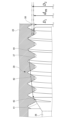
- Figure 3 is an enlarged side view of the male thread portion 37 of the screw head 30 of the first embodiment.
- the male thread portion 37 includes a first tapered portion 41, a second tapered portion 42, a transition portion 43, and a fully threaded portion 44.
- the first tapered portion 41 is located on the tip side of the screw head 30 in the male thread portion 37, and is adjacent to the constricted portion 36.
- the average gradient g1 of the first tapered portion 41 can be expressed by the following mathematical formula 1.
- h1 indicates the radial length (height) of the first tapered portion 41 in the axial direction, obtained by subtracting the radius of the portion on the tip side of the screw head 30 from the radius of the portion on the rear end side of the screw head 30.
- l1 is the axial length of the first tapered portion 41 from the portion on the rear end side to the portion on the tip side.
- the second tapered portion 42 has a tip side connected to the first tapered portion 41 via a transition portion 43 and a rear end side connected to the complete thread portion 44.
- the average gradient g2 of the second tapered portion 42 can be expressed by the following mathematical formula 2.
- h2 indicates the radial length (height) of the second tapered portion 42 in the axial direction, obtained by subtracting the radius of the portion on the tip side of the screw head 30 from the radius of the portion on the rear end side of the screw head 30.
- l2 is the axial length of the second tapered portion 42 from the portion on the rear end side to the portion on the tip side.
- the average gradient g 1 of the first tapered portion 41 is set to be larger than the average gradient g 2 of the second tapered portion 42 .
- the transition section 43 is located between the first tapered section 41 and the second tapered section 42. In the first embodiment, the transition section 43 is the portion where the large gradient and the small gradient switch in the male thread section 37.
- the fully threaded portion 44 is located on the screw 23 side of the second tapered portion 42.
- the fully threaded portion 44 is a threaded portion that extends in the axial direction with the same diameter without tapering. In the fully threaded portion 44, the outer diameter of the thread is constant.
- the outer diameter of the male thread portion 37 gradually decreases from the rear end side of the screw head 30 toward the tip side.
- the first tapered portion 41 which has a relatively large gradient, is located on the tip side
- the second tapered portion 42 which has a relatively small gradient, is located on the screw 23 side.
- FIG. 4A is a side view showing the shape of the screw head 130 of Comparative Example 1. Unlike the screw head 30 of the above embodiment, the screw head 130 of Comparative Example 1 in FIG. 4A has only one tapered portion 141 with a gradient of 30 degrees.
- FIG. 4B is a side view showing the shape of the screw head 30 of the embodiment.
- a first tapered portion 41 with a gradient of 30 degrees is formed on the side of the neck portion 36 and on the side of the complete thread portion 44. Note that the axial length of the first tapered portion 41 is shorter than the tapered portion 141 of Comparative Example 1, but due to the presence of the second tapered portion 42, the overall length of the tapered portion is longer in the embodiment than in Comparative Example 1.
- Figure 4C is a side view showing the shape of the screw head 131 of Comparative Example 2. Unlike the screw head 30 of the above embodiment, the screw head 131 of Comparative Example 2 in Figure 4C has only one tapered section 142 with a gradient of six degrees. Because the gradient of the tapered section 142 of Comparative Example 2 is small, the axial length of the tapered section is longer than the tapered section 141 of Comparative Example 1 and the combined length of the first tapered section 41 and the second tapered section 42 of the example.
- Figure 5 is a graph showing the difference in equivalent stress between the comparative example and the working example.
- the graph shown in Figure 5 was obtained by performing an analysis using stress analysis software on each of Comparative Example 1, the working example, and Comparative Example 2.
- the maximum stress value in the thread root portion of each of Comparative Example 1, the working example, and Comparative Example 2 is shown as equivalent stress.
- Comparative Example 2 has a lower equivalent stress value than Comparative Example 1. This is because the amount of engagement between the tapered section 142, which has a small gradient, and the female thread section 50 of the screw 23 gradually increases over several pitches, resulting in a uniform load sharing rate. On the other hand, Comparative Example 2 has a higher equivalent stress value than the examples. This is because the threaded section is tapered at a constant, small gradient from the connection section of the small-diameter constricted section 36, resulting in a larger number of threads on the constricted section 36 side that do not engage with the female thread, and a larger shared load for the engaged threads. The reduction in the shear cross-sectional area due to the reduction in the number of effective threads that engage with the female thread can also cause shear fracture of the threads.
- the equivalent stress value in the example is even lower than that in comparative example 2. This is because the presence of the first tapered section 41 prevents a decrease in the number of effective threads that mesh with the female thread on the constricted section 36 side, and the small gradient of the second tapered section 42 gradually increases the amount of meshing with the female thread, thereby achieving the effect of equalizing the load sharing rate. In other words, the effect of equalizing the load sharing rate is achieved by the second tapered section 42 with its small gradient, and the first tapered section 41 is provided to prevent a decrease in the number of effective threads. In this way, the screw head 30 of the injection molding machine 1 according to the first embodiment provides the following effects.
- the screw head 30 attached to the tip of the screw 23 for the injection molding machine 1 of the first embodiment has a neck portion 32 located on the screw 23 side relative to the neck portion 31 located on the tip side of the screw head 30, and a male threaded portion 37 that screws into the screw 23, and a constricted portion 36 located on the tip side of the male threaded portion 37 and having a diameter d1 smaller than the valley diameter d2 of the male threaded portion 37.
- the male threaded portion 37 has a first tapered portion 41 located on the constricted portion 36 side and having an outer diameter that decreases as it progresses toward the constricted portion 36, a transition portion 43 located on the screw 23 side of the first tapered portion 41, and a second tapered portion 42 adjacent to the first tapered portion 41 across the transition portion 43 and having an outer diameter that decreases as it progresses toward the constricted portion 36, and the first tapered portion 41 is formed with a greater average gradient than the second tapered portion 42. This equalizes the load sharing rate of each thread of the male thread portion 37, and can alleviate the significant stress concentration that constantly occurs in the thread root due to fastening to the screw 23.
- the fatigue strength of the thread root against tensile and compressive external forces can be improved.
- the configuration of the first embodiment can achieve an appropriate balance between the fatigue strength of the thread portion and the static strength of the neck portion.
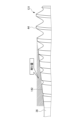
- Fig. 6 is a side view showing the screw head 30a of the second embodiment and the female screw portion 50 of the screw.
- Fig. 6 shows the cross section of the female screw portion 50 of the screw 23 together with the screw head 30a of the second embodiment.
- the second tapered portion 42 is intended to equalize the load sharing rate of the threads by gradually meshing with the female thread portion 50 of the screw, and its presence in a non-meshing portion is meaningless. Therefore, in order to prevent the amount of effective thread reduction from becoming greater than necessary, the outer diameter of the transition portion 43 can be made larger than the inner diameter of the female thread portion 50.
- the transition (change in gradient) from the first tapered portion 41 to the second tapered portion 42 is too slow, the male thread will already be meshing with the female thread a lot at the transition portion 43, and the length of meshing between the second tapered portion 42 and the female thread portion 50 of the screw will be short.
- the role of equalizing the load sharing rate that should be played by the second tapered portion will be played by the first tapered portion, which has a larger gradient, and the effect will be reduced.
- the outer diameter of the transition portion 43 should be made smaller than the effective diameter of the female thread portion 50.
- the screw head 30a in order to balance the reduction amount of the thread and the uniformity of the load sharing rate, is configured to satisfy the relationship of mathematical formula 4.
- dm represents the outer diameter of the transition portion 43 between the first tapered portion 41 and the second tapered portion 42
- D1 represents the inner diameter of the female thread portion 50
- D2 represents the effective diameter of the female thread portion 50.
- the outer diameter dm of the transition portion 43 is formed to be larger than the inner diameter D1 of the female thread portion 50 provided at the tip of the screw 23. This makes it possible to effectively prevent a reduction in the effect of mitigating the load sharing rate of the first thread due to a reduction in the number of effective threads and a decrease in the shear strength of the threads.
- the outer diameter dm of the transition portion 43 is smaller than the effective diameter D2 of the female thread portion 50 provided on the tip side of the screw 23. This effectively prevents the first tapered portion, which has a large gradient, from meshing with the female thread too much, thereby reducing the effect of equalizing the load sharing rate.
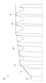
- FIG. 7 is a side view of the screw head 30b according to the third embodiment.
- the configuration of the second tapered portion 42a is different from that of the above-mentioned embodiment.
- the gradient of the second tapered portion 42a is not constant, but is smaller on the tip (transition portion 43) side and larger on the screw 23 (full thread portion 44) side.
- the gradient of the second tapered portion 42a is formed like a circular arc rising from bottom to top.
- the gradient of the second tapered portion 42a is configured to increase from the transition portion 43 side toward the screw 23 side.
- the effect of equalizing the load sharing rate is greater as the gradient of the gradient of the gradient is smaller, but the reduction in the shear cross-sectional area of the thread also increases accordingly, increasing the risk of shear fracture.
- the gradient of the second tapered portion 42a can be kept small where the male and female threads begin to mesh, which has a large effect on equalizing the load sharing rate, and the gradient can be made large at the rear end side, where the effect is small. This realizes a configuration of the screw head 30b that achieves a high effect of equalizing the load sharing rate while suppressing the reduction in the shear cross-sectional area of the thread.
- FIG. 8 is a side view showing the screw head 30c according to the fourth embodiment.
- the configuration of the transition portion 43a is different from that of the above-mentioned embodiments.
- the transition portion 43a in the male thread portion 37b of the fourth embodiment has a constant length in the axial direction, unlike the transition portion 43 in the above embodiment.
- the transition portion 43a is formed in a columnar or cylindrical shape with an outer diameter larger than the inner diameter D1 of the female thread portion 50, and has a circumferential surface 45.
- the transition portion 43a may be configured to include a screw thread or a screw root.
- the transition portion 43a is formed so as to extend in the axial direction with the same outer diameter, and the outer diameter of the transition portion 43a is formed to be larger than the inner diameter D1 of the female thread portion 50 of the screw 23.
- the outer diameter of the transition portion 43a is larger than the inner diameter D1 , which is the diameter at which the engagement with the female thread portion 50 begins, the transition portion 43a itself, together with the second tapered portion 42, can contribute to equalizing the load sharing rate.
- FIG. 9 is a side view showing the screw head 30d according to the fifth embodiment.
- the axial length of the transition portion 43b is different from that of the fourth embodiment.
- the axial length d3 of the transition portion 43 in the male thread portion 37c is set to be greater than the pitch d4 of the thread.
- the pitch d4 of the thread is between the threads or between the roots of the thread in the fully threaded portion 44.
- the axial length of the transition portion 43b is equal to or greater than the pitch d4 of the thread. This allows highly reliable dimensional measurements to be made using a measuring device such as a micrometer, so the outer diameter of the transition portion 43b can be more appropriately controlled, and the effect of improving the strength of the threaded portion can be more stably achieved.
- the tapered portion is configured to taper in two stages, the first tapered portion and the second tapered portion, but this is not limited to this configuration.
- the tapered portion of the male thread may have three or more stages of change in slope. In this way, the slope change can be changed as appropriate depending on the circumstances.
- the male thread portion (37, 37a, 37b, 37c) is a first tapered portion (41) located on the side of the constricted portion (36) and having an outer diameter that decreases as it advances toward the constricted portion (36), a transition portion
- the outer diameter (d m ) of the transition portion (43) is formed to be larger than the inner diameter (D 1 ) of the female thread portion (50) provided on the tip side of the screw (22).
- the outer diameter (d m ) of the transition portion (43) is formed smaller than the effective diameter (D 2 ) of the female thread portion (50) provided on the tip side of the screw (22).
- the gradient of the second tapered portion (42a) is configured to increase from the transition portion (43) side toward the screw (22) side.
- transition portions (43a, 43b) are formed to extend in the axial direction with the same outer diameter,
- the outer diameter of the transition portions (43a, 43b) is formed to be larger than the inner diameter of the female thread portion of the screw (22).
- the axial length of the transition portion (43b) is equal to or greater than the pitch of the thread.
Landscapes
- Engineering & Computer Science (AREA)
- Manufacturing & Machinery (AREA)
- Mechanical Engineering (AREA)
- Injection Moulding Of Plastics Or The Like (AREA)
Priority Applications (4)
| Application Number | Priority Date | Filing Date | Title |
|---|---|---|---|
| DE112023004918.1T DE112023004918T5 (de) | 2023-02-17 | 2023-02-17 | Schneckenkopf für Spritzgießmaschine |
| PCT/JP2023/005655 WO2024171425A1 (ja) | 2023-02-17 | 2023-02-17 | 射出成形機のスクリュヘッド |
| JP2025500579A JPWO2024171425A1 (https=) | 2023-02-17 | 2023-02-17 | |
| CN202380092593.6A CN120603694A (zh) | 2023-02-17 | 2023-02-17 | 注射成型机的螺杆头 |
Applications Claiming Priority (1)
| Application Number | Priority Date | Filing Date | Title |
|---|---|---|---|
| PCT/JP2023/005655 WO2024171425A1 (ja) | 2023-02-17 | 2023-02-17 | 射出成形機のスクリュヘッド |
Publications (1)
| Publication Number | Publication Date |
|---|---|
| WO2024171425A1 true WO2024171425A1 (ja) | 2024-08-22 |
Family
ID=92421347
Family Applications (1)
| Application Number | Title | Priority Date | Filing Date |
|---|---|---|---|
| PCT/JP2023/005655 Ceased WO2024171425A1 (ja) | 2023-02-17 | 2023-02-17 | 射出成形機のスクリュヘッド |
Country Status (4)
| Country | Link |
|---|---|
| JP (1) | JPWO2024171425A1 (https=) |
| CN (1) | CN120603694A (https=) |
| DE (1) | DE112023004918T5 (https=) |
| WO (1) | WO2024171425A1 (https=) |
Citations (3)
| Publication number | Priority date | Publication date | Assignee | Title |
|---|---|---|---|---|
| JPS59143719U (ja) * | 1983-03-15 | 1984-09-26 | 住友重機械工業株式会社 | 射出成形機用スクリユ−ヘツド |
| JPS6317017A (ja) * | 1986-07-10 | 1988-01-25 | Meiki Co Ltd | 射出成形装置のスクリユ |
| JPH09193219A (ja) * | 1996-01-22 | 1997-07-29 | Toshiba Mach Co Ltd | 射出成形機のスクリュヘッド及びスクリュ |
-
2023
- 2023-02-17 WO PCT/JP2023/005655 patent/WO2024171425A1/ja not_active Ceased
- 2023-02-17 JP JP2025500579A patent/JPWO2024171425A1/ja active Pending
- 2023-02-17 DE DE112023004918.1T patent/DE112023004918T5/de active Pending
- 2023-02-17 CN CN202380092593.6A patent/CN120603694A/zh active Pending
Patent Citations (3)
| Publication number | Priority date | Publication date | Assignee | Title |
|---|---|---|---|---|
| JPS59143719U (ja) * | 1983-03-15 | 1984-09-26 | 住友重機械工業株式会社 | 射出成形機用スクリユ−ヘツド |
| JPS6317017A (ja) * | 1986-07-10 | 1988-01-25 | Meiki Co Ltd | 射出成形装置のスクリユ |
| JPH09193219A (ja) * | 1996-01-22 | 1997-07-29 | Toshiba Mach Co Ltd | 射出成形機のスクリュヘッド及びスクリュ |
Also Published As
| Publication number | Publication date |
|---|---|
| DE112023004918T5 (de) | 2025-09-25 |
| CN120603694A (zh) | 2025-09-05 |
| JPWO2024171425A1 (https=) | 2024-08-22 |
Similar Documents
| Publication | Publication Date | Title |
|---|---|---|
| EP2302224B1 (en) | Screw fastening structure with high-strength self-forming screw | |
| CN101424295A (zh) | 用于受控刚度的螺纹牙形改进 | |
| MX2014009237A (es) | Tuerca. | |
| WO2024171425A1 (ja) | 射出成形機のスクリュヘッド | |
| CN101796312B (zh) | 具有可变间隙的螺纹连接 | |
| CN202914489U (zh) | 一种复合螺栓 | |
| CN204437030U (zh) | 一种高强度螺母 | |
| CN205956174U (zh) | 新型高锁螺母及使用该高锁螺母的锁紧组件 | |
| CN101837486A (zh) | 一种可换头式带有TiN复合涂层的硬质合金球头铣刀 | |
| US7513191B2 (en) | Piston head for hydraulic injection molding machine | |
| CN205478791U (zh) | 螺栓和螺母组件 | |
| CN214395275U (zh) | 一种均化效果好的螺杆 | |
| CN204591927U (zh) | 一种额定预紧力轻型螺栓结构 | |
| CN204961531U (zh) | 一种压力机固定拉杠用螺母 | |
| CN211901216U (zh) | 一种螺纹紧固件及螺纹副 | |
| CN110239046A (zh) | 一种半环抱闸式连接的锁模油缸 | |
| US367011A (en) | Chaeles d | |
| CN208787695U (zh) | 一种组合丝锥 | |
| CN102954087A (zh) | 一种注塑机弹性拉杆螺母 | |
| CN203035705U (zh) | 一种注塑机弹性拉杆螺母 | |
| CN103171082B (zh) | 注塑机的导柱结构及其控制方法 | |
| CN116097010A (zh) | 固定元件和包括固定元件的调设系统 | |
| KR102060574B1 (ko) | 체결력 및 풀림방지력이 개선된 태핑스크류 | |
| JP2612086B2 (ja) | 射出成形機のスクリュヘッド | |
| CN206943163U (zh) | 一种阶梯定位销结构 |
Legal Events
| Date | Code | Title | Description |
|---|---|---|---|
| 121 | Ep: the epo has been informed by wipo that ep was designated in this application |
Ref document number: 23922760 Country of ref document: EP Kind code of ref document: A1 |
|
| WWE | Wipo information: entry into national phase |
Ref document number: 112023004918 Country of ref document: DE |
|
| WWE | Wipo information: entry into national phase |
Ref document number: 202380092593.6 Country of ref document: CN |
|
| ENP | Entry into the national phase |
Ref document number: 2025500579 Country of ref document: JP Kind code of ref document: A |
|
| WWE | Wipo information: entry into national phase |
Ref document number: 2025500579 Country of ref document: JP |
|
| WWP | Wipo information: published in national office |
Ref document number: 202380092593.6 Country of ref document: CN |
|
| WWP | Wipo information: published in national office |
Ref document number: 112023004918 Country of ref document: DE |
|
| 122 | Ep: pct application non-entry in european phase |
Ref document number: 23922760 Country of ref document: EP Kind code of ref document: A1 |