WO2024167009A1 - 蓄電デバイス、蓄電デバイス用ケースおよび蓄電デバイス用外装材 - Google Patents
蓄電デバイス、蓄電デバイス用ケースおよび蓄電デバイス用外装材 Download PDFInfo
- Publication number
- WO2024167009A1 WO2024167009A1 PCT/JP2024/004645 JP2024004645W WO2024167009A1 WO 2024167009 A1 WO2024167009 A1 WO 2024167009A1 JP 2024004645 W JP2024004645 W JP 2024004645W WO 2024167009 A1 WO2024167009 A1 WO 2024167009A1
- Authority
- WO
- WIPO (PCT)
- Prior art keywords
- storage device
- heat
- layer
- gas barrier
- barrier layer
- Prior art date
- Legal status (The legal status is an assumption and is not a legal conclusion. Google has not performed a legal analysis and makes no representation as to the accuracy of the status listed.)
- Ceased
Links
Images





Classifications
-
- H—ELECTRICITY
- H01—ELECTRIC ELEMENTS
- H01M—PROCESSES OR MEANS, e.g. BATTERIES, FOR THE DIRECT CONVERSION OF CHEMICAL ENERGY INTO ELECTRICAL ENERGY
- H01M50/00—Constructional details or processes of manufacture of the non-active parts of electrochemical cells other than fuel cells, e.g. hybrid cells
- H01M50/10—Primary casings; Jackets or wrappings
- H01M50/116—Primary casings; Jackets or wrappings characterised by the material
- H01M50/124—Primary casings; Jackets or wrappings characterised by the material having a layered structure
- H01M50/126—Primary casings; Jackets or wrappings characterised by the material having a layered structure comprising three or more layers
- H01M50/129—Primary casings; Jackets or wrappings characterised by the material having a layered structure comprising three or more layers with two or more layers of only organic material
-
- H—ELECTRICITY
- H01—ELECTRIC ELEMENTS
- H01M—PROCESSES OR MEANS, e.g. BATTERIES, FOR THE DIRECT CONVERSION OF CHEMICAL ENERGY INTO ELECTRICAL ENERGY
- H01M50/00—Constructional details or processes of manufacture of the non-active parts of electrochemical cells other than fuel cells, e.g. hybrid cells
- H01M50/10—Primary casings; Jackets or wrappings
- H01M50/102—Primary casings; Jackets or wrappings characterised by their shape or physical structure
- H01M50/105—Pouches or flexible bags
-
- H—ELECTRICITY
- H01—ELECTRIC ELEMENTS
- H01M—PROCESSES OR MEANS, e.g. BATTERIES, FOR THE DIRECT CONVERSION OF CHEMICAL ENERGY INTO ELECTRICAL ENERGY
- H01M50/00—Constructional details or processes of manufacture of the non-active parts of electrochemical cells other than fuel cells, e.g. hybrid cells
- H01M50/10—Primary casings; Jackets or wrappings
- H01M50/116—Primary casings; Jackets or wrappings characterised by the material
- H01M50/117—Inorganic material
- H01M50/119—Metals
-
- H—ELECTRICITY
- H01—ELECTRIC ELEMENTS
- H01M—PROCESSES OR MEANS, e.g. BATTERIES, FOR THE DIRECT CONVERSION OF CHEMICAL ENERGY INTO ELECTRICAL ENERGY
- H01M50/00—Constructional details or processes of manufacture of the non-active parts of electrochemical cells other than fuel cells, e.g. hybrid cells
- H01M50/10—Primary casings; Jackets or wrappings
- H01M50/116—Primary casings; Jackets or wrappings characterised by the material
- H01M50/121—Organic material
-
- H—ELECTRICITY
- H01—ELECTRIC ELEMENTS
- H01M—PROCESSES OR MEANS, e.g. BATTERIES, FOR THE DIRECT CONVERSION OF CHEMICAL ENERGY INTO ELECTRICAL ENERGY
- H01M50/00—Constructional details or processes of manufacture of the non-active parts of electrochemical cells other than fuel cells, e.g. hybrid cells
- H01M50/10—Primary casings; Jackets or wrappings
- H01M50/131—Primary casings; Jackets or wrappings characterised by physical properties, e.g. gas permeability, size or heat resistance
-
- H—ELECTRICITY
- H01—ELECTRIC ELEMENTS
- H01M—PROCESSES OR MEANS, e.g. BATTERIES, FOR THE DIRECT CONVERSION OF CHEMICAL ENERGY INTO ELECTRICAL ENERGY
- H01M50/00—Constructional details or processes of manufacture of the non-active parts of electrochemical cells other than fuel cells, e.g. hybrid cells
- H01M50/10—Primary casings; Jackets or wrappings
- H01M50/183—Sealing members
- H01M50/186—Sealing members characterised by the disposition of the sealing members
-
- Y—GENERAL TAGGING OF NEW TECHNOLOGICAL DEVELOPMENTS; GENERAL TAGGING OF CROSS-SECTIONAL TECHNOLOGIES SPANNING OVER SEVERAL SECTIONS OF THE IPC; TECHNICAL SUBJECTS COVERED BY FORMER USPC CROSS-REFERENCE ART COLLECTIONS [XRACs] AND DIGESTS
- Y02—TECHNOLOGIES OR APPLICATIONS FOR MITIGATION OR ADAPTATION AGAINST CLIMATE CHANGE
- Y02E—REDUCTION OF GREENHOUSE GAS [GHG] EMISSIONS, RELATED TO ENERGY GENERATION, TRANSMISSION OR DISTRIBUTION
- Y02E60/00—Enabling technologies; Technologies with a potential or indirect contribution to GHG emissions mitigation
- Y02E60/10—Energy storage using batteries
Definitions
- This invention relates to electricity storage devices such as all-solid-state batteries used as high-power batteries such as vehicle batteries, batteries for portable devices such as mobile electronic devices, and batteries for storing regenerative energy, as well as cases and exterior materials for electricity storage devices used in such electricity storage devices.
- electricity storage devices such as all-solid-state batteries used as high-power batteries such as vehicle batteries, batteries for portable devices such as mobile electronic devices, and batteries for storing regenerative energy, as well as cases and exterior materials for electricity storage devices used in such electricity storage devices.
- the lithium-ion secondary batteries that have been widely used up until now use a liquid electrolyte, which means that leakage or the formation of dendrites can destroy the separator, and in some cases, can lead to a short circuit and cause a fire.
- all-solid-state batteries use a solid electrolyte, so there is no risk of leakage or dendrites, and the separator is not destroyed. Therefore, there is no risk of fire caused by separator destruction, and they are attracting a lot of attention from the perspective of safety, etc.
- Normal all-solid-state batteries are constructed by sealing the all-solid-state battery body, including the electrode active material and solid electrolyte, inside an exterior material that acts as a casing.
- an exterior material that acts as a casing.
- the basic structure of the exterior material for solid-state batteries includes a metal foil layer and a heat-sealing layer (sealant layer) laminated on the inside of the metal foil layer, and the sealant layer is heat-sealed to encapsulate the solid-state battery body.
- the all-solid-state battery exterior material shown in Patent Document 1 below has a protective film interposed between a metal foil layer and a sealant layer, and uses a sealant layer with high hydrogen sulfide gas permeability.
- the all-solid-state battery exterior material shown in Patent Document 2 uses a sealant layer with low hydrogen sulfide gas permeability.
- the all-solid-state battery exterior material shown in Patent Document 3 uses a sealant layer that absorbs gas.
- the all-solid-state battery exterior material shown in Patent Document 4 is configured by laminating a vapor deposition film layer on the inner surface of the sealant layer.
- the conventional all-solid-state batteries described above have the problem that gases such as hydrogen sulfide gas generated by the reaction between the solid electrolyte and water may leak out.
- the preferred embodiments of the present invention have been made in light of the above and/or other problems in the related art.
- the preferred embodiments of the present invention provide significant improvements over existing methods and/or apparatus.
- This invention was made in consideration of the above problems, and aims to provide an electricity storage device, a case for an electricity storage device, and an exterior material for an electricity storage device that can ensure sufficient cooling while preventing leakage of hydrogen sulfide gas and the like.
- the present invention provides the following:
- a case for an electricity storage device comprising a case main body having a top wall, a side wall provided on an outer peripheral edge portion of the top wall, and a flange provided on the outer periphery of the side wall, and a storage portion provided inside the top wall and the side wall,
- the case body is formed of a molded body of an exterior material for an electricity storage device
- the electrical storage device exterior material includes a resin base layer, a metal foil layer laminated on an inner surface side of the base layer, a resin heat-resistant gas barrier layer laminated on the inner surface side of the metal foil layer, and a resin sealant layer laminated on the inner surface side of the heat-resistant gas barrier layer, an opening is provided in the sealant layer to expose the heat-resistant gas barrier layer to the inside of the storage portion;
- the case for an electricity storage device wherein an outer peripheral edge of the opening is set in the top wall.
- the blocking member includes a resin base layer, a metal foil layer laminated on an inner surface side of the base layer, a resin heat-resistant gas barrier layer laminated on the inner surface side of the metal foil layer, and a resin sealant layer laminated on the inner surface side of the heat-resistant gas barrier layer, 3.
- the electricity storage device according to item 2 wherein an opening is provided in the sealant layer of the blocking member to expose the heat-resistant gas barrier layer of the blocking member to the storage portion.
- An exterior material for an electricity storage device used in the case for the electricity storage device according to the preceding item 1 It has a sheet-like shape, a planned opening portion that is to become the opening portion and a planned top wall portion that is to become the top wall, An exterior material for an electricity storage device, wherein an outer peripheral edge portion of the intended opening portion is set in the intended top wall portion.
- a heat-resistant gas barrier layer is provided between the metal foil layer and the sealant layer, and an opening is formed in the sealant layer of the top wall. Therefore, when the electric storage device body is sealed to manufacture the electric storage device, the opening without the sealant layer is provided, and the heat generated from the electric storage device body is not blocked by the sealant layer, but is efficiently transferred to the metal foil layer through the opening and the heat-resistant gas barrier layer, and dissipated, ensuring sufficient heat dissipation and cooling properties.
- the heat-resistant gas barrier layer is disposed on the inner surface side of the metal foil layer, even if the solid electrolyte of the electric storage device body reacts with moisture in the outside air to generate hydrogen sulfide gas or the like, the gas can be reliably prevented from leaking by the heat-resistant gas barrier layer.
- the sealant layer is laminated on the heat-resistant gas barrier layer from a part of the top wall through the side wall to the flange, sufficient sealing strength against the heat-resistant gas barrier layer can be obtained, and inadvertent delamination can be prevented.
- the electricity storage device of the invention [2] can reliably prevent the leakage of gases such as hydrogen sulfide gas while ensuring sufficient heat dissipation and cooling properties.
- openings are also formed in the sealant layer of the blocking member, which further improves heat dissipation and cooling properties.
- the exterior material for an electricity storage device of invention [4] can reliably prevent the leakage of gases such as hydrogen sulfide gas while ensuring sufficient heat dissipation and cooling properties when the electricity storage device is manufactured, as described above.
- the sealant layer remains around the entire periphery of the top wall, which allows for greater elongation around the molded part of the top wall, resulting in good moldability, while also ensuring a large opening area for the opening, ensuring sufficient heat dissipation and cooling properties.
- the exterior material for an electricity storage device of invention [6] makes it possible to more reliably leave a sealant layer around the entire periphery of the top wall when forming the top wall and side walls, thereby further improving formability.
- the exterior material for an electricity storage device of invention [7] improves the slipperiness of the heat-resistant gas barrier layer against the forming punch, further improving formability.
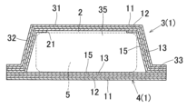
- FIG. 1 is a schematic cross-sectional view showing an all-solid-state battery as an electricity storage device according to an embodiment of the present invention.
- FIG. 2 is an enlarged schematic cross-sectional view showing a main part of FIG.
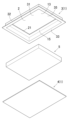
- FIG. 3 is an exploded perspective view illustrating a schematic diagram of the all-solid-state battery according to the embodiment.
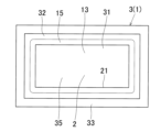
- FIG. 4 is a bottom view (inner view) illustrating a schematic diagram of a case main body in the all-solid-state battery according to the embodiment.
- FIG. 5 is a schematic cross-sectional view showing an exterior material for a case body in an all-solid-state battery according to an embodiment.
- FIG. 6 is a schematic cross-sectional view for explaining a method for forming an opening in the exterior material of the embodiment.
- FIG. 1 is a schematic cross-sectional view showing an all-solid-state battery as an electricity storage device according to an embodiment of the present invention.
- FIG. 2 is an enlarged schematic cross-sectional view showing a main part of FIG.
- FIG. 7 is a schematic cross-sectional view showing a mold device for molding a case body using the exterior material of the embodiment.
- FIG. 8 is a schematic cross-sectional view for explaining the heat sealing method in the embodiment.
- FIG. 9 is a schematic cross-sectional view showing an all-solid-state battery according to a first modified example of the present invention.
- FIG. 10 is a schematic cross-sectional view showing an all-solid-state battery according to a second modified example of the present invention.
- FIG. 1 is a schematic cross-sectional view showing an all-solid-state battery as an electricity storage device according to an embodiment of the present invention
- FIG. 2 is a schematic cross-sectional view showing an enlarged view of a main portion of FIG. 1
- FIG. 3 is an exploded perspective view showing a schematic of the all-solid-state battery according to the embodiment.
- the all-solid-state battery according to this embodiment comprises a case body 3 and a blocking member 4 as a casing, and an all-solid-state battery body 5 housed and sealed within the casing.
- FIG. 5 is a schematic cross-sectional view showing the exterior material 1 constituting the case body 3 in the all-solid-state battery of the embodiment.
- the exterior material 1 includes a base layer 11 arranged on the outermost side, a metal foil layer 12 laminated and bonded to the inner side of the base layer 11 via an adhesive layer, a heat-resistant gas barrier layer 13 laminated and bonded to the inner side of the metal foil layer 12 via an adhesive layer, and a sealant layer 15 laminated and bonded to the inner side of the heat-resistant gas barrier layer 13 via an adhesive layer 14.
- the direction of the base layer 11 (upper side in FIG. 3) is referred to as the outer side
- the direction of the sealant layer 15 lower side in FIG. 3) is referred to as the inner side.
- the exterior material 1 constituting the blocking member 4 has the same structure as the exterior material 1 constituting the case body 3.
- FIG. 4 is a schematic diagram of the case body 3 as viewed from the bottom side (inner side).
- the case body 3 is formed of a molded body of the exterior material 1, and integrally includes a top wall 31, a side wall (circumferential side wall) 32 extending downward from the outer periphery of the top wall 31, and a flange 33 provided on the outer periphery of the lower end of the side wall 32, and a storage section 35 is formed inside the top wall 31 and the side wall 32.
- the blocking member 4 is also formed of the sheet-like exterior material 1.
- the solid-state battery body 5 is accommodated in the storage section 35 of the case body 3, and the blocking member 4 is arranged so as to block the lower end open part of the storage section 35.
- the blocking member 4 is arranged with its sealant layer 15 facing inward (upper side), and is arranged so that the sealant layer 15 of the flange 33 of the case body 3 and the sealant layer 15 of the outer periphery of the blocking member 4 face each other and are overlapped.
- the overlapping sealant layers 15 are bonded together by thermal bonding (heat sealing) to produce an all-solid-state battery in which the all-solid-state battery body 5 is housed in a sealed state within the casing (case body 3 and closing member 4).
- the sealant layer 15 and adhesive layer 14 are removed from the case body 3 of the all-solid-state battery in a portion corresponding to the top wall 31 to form an opening 2. Furthermore, the sealant layer 15 and adhesive layer 14 are removed from the blocking member 4 in a portion corresponding to the storage section 35 to form an opening 2. Through the opening 2 of the case body 3 and the blocking member 4, the heat-resistant gas barrier layer 13 of the exterior material 1 is exposed inside the storage section 35 and is disposed so as to face the all-solid-state battery body 5.
- a tab lead is provided for electrical extraction, although not shown in the drawings.
- One end (inner end) of this tab lead is adhesively fixed to the all-solid-state battery body 5, and the middle part is arranged so that it passes through the heat seal part between the flange 33 of the case body 3 and the outer periphery of the blocking member 4, and the other end side is pulled out to the outside.
- the base material layer 11 of the exterior material 1 is composed of a heat-resistant resin film with a thickness of 5 ⁇ m to 50 ⁇ m.
- the resin that composes this base material layer 11 can be suitably made of oriented polyamide film, oriented polyester (PET, PBT, PEN, etc.), oriented polyolefin (PE, PP, etc.), etc.
- the metal foil layer 12 has a thickness set to 5 ⁇ m to 120 ⁇ m, and has the function of blocking the penetration of oxygen and moisture from the surface (outer surface) side.
- Aluminum foil, SUS foil (stainless steel foil), copper foil, nickel foil, etc. can be suitably used as this metal foil layer 12.
- the terms "aluminum”, “copper”, and “nickel” are used to include their alloys.
- the metal foil layer 12 by subjecting the metal foil layer 12 to a plating process or the like, the risk of pinholes occurring is reduced, and the ability to block the intrusion of oxygen and moisture can be further improved.
- the corrosion resistance is further improved, so that defects such as chipping can be more reliably prevented, and the adhesion to the resin can be improved, further improving durability.
- the sealant layer (thermally adhesive resin layer) 15 has a thickness set to 20 ⁇ m to 100 ⁇ m, and is made of a film of thermally adhesive (thermally adhesive) resin.
- Suitable resins for making up this sealant layer 15 include polyethylene (LLDPE, LDPE, HDPE), polyolefins such as polypropylene, olefin copolymers, acid-modified products thereof, and ionomers, such as non-oriented polypropylene (CPP, IPP).
- the heat-resistant gas barrier layer 13 is composed of a resin film having heat resistance and insulating properties.
- the resin that composes the heat-resistant gas barrier layer 13 is preferably polyamide (6-nylon, 66-nylon, MXD nylon, etc.), polyester (polyethylene terephthalate (PET) etc.), polybutylene terephthalate (PBT), polyethylene naphthalate (PEN)), cellophane, polyvinylidene chloride (PVDC), oriented polypropylene (OPP), etc.
- the resin constituting the heat-resistant gas barrier layer 13 preferably has a predetermined hydrogen sulfide (H 2 S) gas permeability.
- the heat-resistant gas barrier layer 13 is preferably made of a resin having a hydrogen sulfide gas permeability of 15 ⁇ cc ⁇ mm/(m 2 ⁇ D ⁇ MPa) ⁇ or less, preferably 10 ⁇ cc ⁇ mm/(m 2 ⁇ D ⁇ MPa) ⁇ or less, and more preferably 4.0 ⁇ cc ⁇ mm/(m 2 ⁇ D ⁇ MPa) ⁇ or less, as measured in accordance with JIS K7126-1.
- the heat-resistant gas barrier layer 13 can prevent the hydrogen sulfide gas from leaking to the outside.
- the hydrogen sulfide gas permeability of the heat-resistant gas barrier layer 13 is too high, there is a risk that the generated hydrogen sulfide gas will pass through the exterior material 1 (heat-resistant gas barrier layer 13) and leak to the outside, which is not preferable.
- the thickness (original thickness) of the heat-resistant gas barrier layer 13 is preferably set to 3 ⁇ m to 50 ⁇ m, and more preferably to 10 ⁇ m to 40 ⁇ m.
- the thickness of the heat-resistant gas barrier layer 13 is set in this range, the above-mentioned hydrogen sulfide gas and water vapor gas permeation suppression effect can be reliably obtained, and even if the sealant layer 15 melts and flows out due to thermal adhesion, the heat-resistant gas barrier layer 13 can reliably ensure insulation.
- the heat-resistant gas barrier layer 13 is too thin, there is a risk that the gas permeation suppression effect and insulation cannot be ensured, which is not preferable.
- the heat-resistant gas barrier layer 13 is too thick, not only will it be impossible to thin the exterior material 1, but the effect of making it thicker than necessary will not be fully obtained, which is also not preferable.
- the entire film becomes the barrier layer, so unlike vapor deposition films, etc., no barrier cracks occur and the barrier properties can be improved.
- the resin film constituting the heat-resistant gas barrier layer 13 may be a non-stretched film or a slightly stretched film, and it is particularly preferable to use a non-stretched film. In other words, when a non-stretched film is used, the moldability and gas barrier properties can be further improved.
- the heat-resistant gas barrier layer 13 of this embodiment has good insulating properties, and maintains good insulating properties even after the all-solid-state battery body 5 is enclosed (sealed) by the case body 3 and the blocking member 4 as the exterior material 1 of this embodiment.
- a heat-resistant gas barrier layer 13 having a surface roughness with an arithmetic mean height Sa of 0.04 ⁇ m to 1.5 ⁇ m.
- the slipperiness against the forming punch 7 is improved, and formability is improved, which is preferable.
- the arithmetic mean height Sa is less than 0.04 ⁇ m, the contact area with the forming punch 7 is large, which increases frictional resistance and may result in reduced formability, which is not preferable.
- the arithmetic mean height Sa exceeds 1.5 ⁇ m, there is a risk of adhesive defects occurring in the adhesive layer 14, which is not preferable as the adhesiveness is reduced.
- the adhesive constituting the adhesive layer 14 that bonds between the heat-resistant gas barrier layer 13 and the sealant layer 15 can be of a two-component curing type, an energy ray (UV, X-ray, etc.) curing type, etc., and among these, urethane-based adhesives, olefin-based adhesives, acrylic-based adhesives, epoxy-based adhesives, etc. can be preferably used. Furthermore, the thickness of the adhesive layer 14 is set to 2 ⁇ m to 5 ⁇ m.
- the adhesive used to bond between the base layer 11 and the metal foil layer 12, and between the metal foil layer 12 and the heat-resistant gas barrier layer 13 can be the same as the adhesive used for the adhesive layer 14, and it is preferable to set the thickness to the same.
- the opening 2 on the case body 3 side has its outer peripheral edge 21 provided on the top wall 31 of the case body 3. Furthermore, the opening 2 on the blocking member 4 side is formed to correspond to the bottom surface of the all-solid-state battery body 5.
- the opening 2 formed in the case body 3 and the blocking member 4 does not have an adhesive layer 14 for bonding the sealant layer 15 to the heat-resistant gas barrier layer 13, and the heat-resistant gas barrier layer 13 is exposed (exposed) to the inside through the opening 2, and when the all-solid-state battery is fabricated, the heat-resistant gas barrier layer 13 is disposed so as to face the upper and lower surfaces of the all-solid-state battery body 5.
- the adhesive layer 14 is not provided on the opening 2, but this is not limited thereto, and the adhesive layer 14 may be provided on at least a portion of the opening 2 in the present invention. However, not providing the adhesive layer 14 as in this embodiment can improve heat dissipation.
- the ratio of the opening area of the opening 2 it is preferable to set the ratio of the opening area of the opening 2 to the area of the entire inner surface of the top wall 31 of the case body 3 at a percentage of 20% to 99%.
- the sealant layer 15 remains on the four sides (all around) including the four corners of the top wall 31, so that when the top wall 31 and side wall 32 are molded using the exterior material 1 described below as a molding material, the sealant layer 15 is arranged corresponding to the shoulder 71 of the punch 7, and the presence of the sealant layer 15 increases the elongation of the peripheral portion of the exterior material 1 intended for the top wall, resulting in good moldability and allowing the production of a molded product (case body) with high precision and high quality.
- the ratio of the opening area is 20% or more, a predetermined opening area can be secured, and sufficient heat dissipation and cooling properties can be secured.
- the distance B from the inner peripheral edge of the top wall 31 to the outer peripheral edge 21 of the opening 2 is preferably set to 1 mm or more, more preferably 2 mm or more.
- the outer peripheral edge 21 of the opening 2 is preferably positioned 1 mm or more inward from the inner peripheral edge of the top wall 31, more preferably 2 mm or more inward.
- the sealant layer 15 remains on the four peripheral sides (all around) including the four corners of the top wall 31, so that when the exterior material 1 is molded as described below, the sealant layer 15 is positioned in correspondence with the shoulder 71 of the punch 7, and the extension of the peripheral edge of the exterior material 1 intended for the top wall increases, resulting in even better moldability.
- the size and shape of the opening 2 provided in the blocking member 4 are not particularly limited, and may be larger or smaller than the bottom surface of the all-solid-state battery body 5. To improve heat dissipation, it is preferable to form the opening 2 of the blocking member 4 large.
- the method for manufacturing the exterior material 1 is not limited (the same applies to the method for manufacturing the case body 3 and the method for manufacturing the all-solid-state battery, which will be described later).
- a laminate without a sealant layer is produced, for example, by a dry lamination method. That is, a resin film for the base layer 11 is adhered, via an adhesive, to the outer surface of the metal foil (metal foil layer 12), which has been subjected to surface treatment and chemical conversion treatment as necessary, and a resin film for the heat-resistant gas barrier layer 13 is adhered, via an adhesive, to the inner surface of the metal foil, producing a laminate without a sealant layer in which the metal foil layer 12 and the heat-resistant gas barrier layer 13 are laminated on the inner surface side of the base layer 11.
- the resin composition for the base layer 11 and the resin composition for the heat-resistant gas barrier layer 13 may be extruded onto the inner and outer surfaces of the metal foil while being laminated, to manufacture the above laminate.
- a resin film for the sealant layer 15 is adhered to the inner surface of the laminate without the sealant layer (the inner surface of the heat-resistant gas barrier layer 13) via an adhesive (adhesive layer 14) to form the sealant layer 15.
- the sealant layer 15 is adjusted so that it can be reliably peeled off and removed from the portion of the sealant layer 15 where the opening 2 is to be formed (planned opening portion 2a) by the following method.
- the opening portion 2a of the sealant layer 15 in the adhesive-uncoated portion 10 is cut out with a laser cutter, a roll blade, or the like (laser cutter, etc.) to form the opening 2 (first formation method).
- a release paper is temporarily attached to the area of the heat-resistant gas barrier layer 13 corresponding to the intended opening portion 2a, and in this state, adhesive is applied to the heat-resistant gas barrier layer 13 with a gravure roll or the like, and a resin film for the sealant layer 15 is attached and dried.
- the intended opening portion 2a of the sealant layer 15 corresponding to the release paper temporary fixing portion is cut out together with the adhesive and release paper using a laser cutter, a roll blade, or the like to form the opening 2.
- a laser cutter, a roll blade, or the like to form the opening 2.
- Another forming method is to form through holes as the openings 2 in the resin film for the sealant layer 15 before bonding the film to the heat-resistant gas barrier layer 13, and then attach the resin film for the sealant layer with the openings to the heat-resistant gas barrier layer 13 via an adhesive (other forming method).
- an adhesive other forming method
- the sheet-like exterior material 1 before molding includes a top wall planned portion 31a which is the portion intended to become the top wall 31, a side wall planned portion 32a which is the portion intended to become the side wall 32, and a flange planned portion 33a which is the portion intended to become the flange 33.
- the intended opening portion 2a is formed in the intended top wall portion 31a of the exterior material 1, and the outer peripheral edge portion 21a of the intended opening portion 2a is set within the range of the intended top wall portion 31a. Furthermore, the ratio of the area of the intended opening portion 2a to the area of the intended top wall portion 31a corresponds to the above-mentioned opening area ratio A, and the distance from the outer peripheral edge portion of the intended top wall portion 31a to the outer peripheral edge portion 21a of the intended opening portion 2a corresponds to the distance B (see Figure 2) from the outer peripheral edge portion of the above-mentioned top wall 31 to the outer peripheral edge portion 21 of the opening 2.
- FIG. 7 is a schematic cross-sectional view showing a die device for forming a case body 3 using an exterior material 1. As shown in the figure, this die device is equipped with a die 6 as an upper die, and a punch 7 and a blank pressing die 70 as a lower die.
- the underside of the die 6 is formed with a molding recess 65 for molding the storage section 35 (top wall 31 and side wall 32) of the case body 3.
- the punch 7 is positioned to correspond to the molding recess 65 of the die 6, and the blank holder die 70 is positioned on the outer periphery of the punch 7 and faces the outer periphery of the lower surface of the die 6.
- the sheet-like exterior material 1 with an opening is placed as the molding material so that its planned top wall portion 31a corresponds to the molding recess 65.
- the planned flange portion 33a of the exterior material 1 is sandwiched and supported by the outer periphery of the die 6 and the blank-holding die 70, and the punch 7 is driven into the molding recess 65 of the die 6, thereby pressing the exterior material 1.
- This forms a case body molded body (molding material) having a storage portion 35 (top wall 31 and side wall 32) and a flange 33 on the outside of the storage portion 35.
- the flange 33 of the molded body is then cut to a predetermined size to produce the case body 3 of this embodiment.
- the opening 2 is placed in the top wall 31 as shown in Figures 1 to 4.
- FIG. 8 is a schematic cross-sectional view for explaining the heat sealing method when the case body 3 and the blocking member 4 are heat-sealed to produce an all-solid-state battery in this embodiment.
- the heat sealing method of this embodiment uses a pair of sealing dies 8 for heat sealing the flange 33 of the case body 3 and the outer peripheral edge of the blocking member 4, which is a sheet-like exterior material 1 in which an opening 2 is formed and which has been cut to a specified size.
- the all-solid-state battery body 5 is housed in the housing section 35 of the case body 3 to be heat-sealed, and the blocking member 4 is arranged so as to block the housing section 35 from below, and the sealant layer 15 of the flange 33 of the case body 3 and the sealant layer 15 of the outer peripheral edge of the blocking member 4 are arranged to face and overlap.
- the flange 33 of the case body 3 and the outer peripheral edge of the blocking member 4 are sandwiched between a pair of sealing dies 8 and heated.
- the overlapping sealant layers 15 are heat-sealed and joined together to produce an all-solid-state battery in which the all-solid-state battery body 5 is housed in an airtight state within the case body 3 and the blocking member 4.
- the resin constituting the sealant layer 15 it is advisable to adjust the resin constituting the sealant layer 15 to have an MFR of 2 to 20 g/10 min (230°C, load 2.16 kgf). That is, when the MFR is in this range, the melting properties during heat sealing are improved, resin pools are easily formed, and the seal strength can be improved. In other words, if the MFR is too low, the resin flow during heat sealing will be poor, making it difficult for resin pools to form, and there is a risk of reduced sealability. Furthermore, if the MFR is too high, there will be too much resin flow during heat sealing, preventing resin pools from forming, and there is a risk of reduced sealability.
- the heat-resistant gas barrier layer 13 is provided between the metal foil layer 12 and the sealant layer 15 in the case body 3 and the blocking member 4, and an opening 2 is formed in the top wall 31 by removing a part of the sealant layer 15. Therefore, the heat generated from the all-solid-state battery body 5 is not blocked by the sealant layer 15, but is efficiently transferred to the metal foil layer 12 through the opening 2 and the heat-resistant gas barrier layer 13 and dissipated, thereby ensuring sufficient heat dissipation and cooling properties. Note that in FIG.
- the outer surface of the all-solid-state battery body 5 and the heat-resistant gas barrier layer 13 are separated from each other at the opening 2, but in reality, the all-solid-state battery body 5 and the heat-resistant gas barrier layer 13 come into contact with each other at the main part of the opening 2.
- the heat-resistant gas barrier layer 13 is disposed on the inner surface side of the metal foil layer 12, even if the solid electrolyte of the all-solid-state battery body 5 reacts with moisture in the outside air to generate hydrogen sulfide gas or the like, the heat-resistant gas barrier layer 13 can reliably prevent the gas from leaking out. Furthermore, the gas permeation prevention action of the heat-resistant gas barrier layer 13 can prevent the intrusion of moisture such as water vapor gas from the outside, so that the generation of hydrogen sulfide gas itself due to the reaction between the moisture and the solid electrolyte can also be suppressed, and the leakage of hydrogen sulfide gas or the like can be more reliably prevented.
- the sealant layer 15 in the case body 3 is laminated over a wide area and three-dimensionally on the heat-resistant gas barrier layer 13 from a part of the top wall 31 through the side wall 32 to the flange 33, so that the sealant layer 15 in the case body 3 can obtain sufficient sealing strength with the heat-resistant gas barrier layer 13 and can prevent the occurrence of inadvertent interlayer peeling.
- the sealant layer 15 in the case body 3 can obtain sufficient sealing strength with the heat-resistant gas barrier layer 13 and can prevent the occurrence of inadvertent interlayer peeling.
- no peeling stress acts between the sealant layer 15 and the heat-resistant gas barrier layer 13, so good sealing strength can be reliably obtained.
- the heat-resistant gas barrier layer 13 can more reliably prevent the intrusion of moisture and can more reliably prevent the generation and leakage of hydrogen sulfide gas.
- the heat conductivity of the heat-resistant gas barrier layer 13 can be sufficiently ensured, so that the cooling performance of the all-solid-state battery body 5 can be further improved.
- the heat-resistant gas barrier layer 13 having insulating properties is disposed therebetween, so that the heat-resistant gas barrier layer 13 can reliably ensure insulation.
- a resin that constitutes the heat-resistant gas barrier layer 13 that has a melting point that is at least 10°C higher than that of the resin that constitutes the sealant layer 15.
- the heat-resistant gas barrier layer 13 has a high melting point, even if the sealant layer 15 melts when the exterior material 1 is thermally bonded, the heat-resistant gas barrier layer 13 can be prevented from melting and flowing out, so that the gas permeation suppression effect and insulating properties of the heat-resistant gas barrier layer 13 can be obtained more reliably.
- the sealant layer 15 is not formed in the portion of the exterior material 1 that corresponds to the all-solid-state battery body 5, so the space for accommodating the all-solid-state battery body 5 can be made larger (thicker). Therefore, in the all-solid-state battery of this embodiment, compared to conventional all-solid-state batteries, a larger-sized all-solid-state battery body 5 can be accommodated without changing the external dimensions of the case body 3, so that it is possible to achieve high output and high capacity while achieving a thinner design.
- the opening 2 is formed in both the case body 3 and the blocking member 4 has been described as an example, but the present invention is not limited to this. As shown in FIG. 9, in the present invention, the opening 2 may be formed in the case body 3, and the opening 2 may not be formed in the blocking member 4.
- the all-solid-state battery of this embodiment shown in FIG. 1 has the case body 3 on the upper side and the blocking member 4 on the lower side, but this is not limited to this.
- the all-solid-state battery shown in FIG. 1 may be inverted, that is, the case body 3, which is a molded body, is placed on the lower side and the sheet-like blocking member 4 is placed on the upper side.
- a molded body may be used as the blocking member 4.
- a tray-shaped molded body having a shape obtained by inverting the case body 3 upside down may be used as the blocking member 4, and the casing of the all-solid-state battery may be formed by the case body 3, which is a molded body, and the tray-shaped blocking member 4, which is also a molded body.
- the blocking member 4 by using a similar configuration for the blocking member 4 as the case body 3, the same effect can be obtained with the blocking member 4.
- the exterior material for an electricity storage device of this invention can be suitably used as a material for a battery case (casing) for housing an all-solid-state battery body such as an all-solid-state battery.
Landscapes
- Chemical & Material Sciences (AREA)
- Chemical Kinetics & Catalysis (AREA)
- Electrochemistry (AREA)
- General Chemical & Material Sciences (AREA)
- Inorganic Chemistry (AREA)
- Sealing Battery Cases Or Jackets (AREA)
Priority Applications (2)
| Application Number | Priority Date | Filing Date | Title |
|---|---|---|---|
| JP2024576916A JPWO2024167009A1 (https=) | 2023-02-10 | 2024-02-09 | |
| US19/294,305 US20250364641A1 (en) | 2023-02-10 | 2025-08-08 | Power storage device, power storage device case, and power storage device exterior material |
Applications Claiming Priority (2)
| Application Number | Priority Date | Filing Date | Title |
|---|---|---|---|
| JP2023-019400 | 2023-02-10 | ||
| JP2023019400 | 2023-02-10 |
Related Child Applications (1)
| Application Number | Title | Priority Date | Filing Date |
|---|---|---|---|
| US19/294,305 Continuation US20250364641A1 (en) | 2023-02-10 | 2025-08-08 | Power storage device, power storage device case, and power storage device exterior material |
Publications (1)
| Publication Number | Publication Date |
|---|---|
| WO2024167009A1 true WO2024167009A1 (ja) | 2024-08-15 |
Family
ID=92263038
Family Applications (1)
| Application Number | Title | Priority Date | Filing Date |
|---|---|---|---|
| PCT/JP2024/004645 Ceased WO2024167009A1 (ja) | 2023-02-10 | 2024-02-09 | 蓄電デバイス、蓄電デバイス用ケースおよび蓄電デバイス用外装材 |
Country Status (3)
| Country | Link |
|---|---|
| US (1) | US20250364641A1 (https=) |
| JP (1) | JPWO2024167009A1 (https=) |
| WO (1) | WO2024167009A1 (https=) |
Citations (4)
| Publication number | Priority date | Publication date | Assignee | Title |
|---|---|---|---|---|
| JP2015520490A (ja) * | 2012-05-18 | 2015-07-16 | 24エム・テクノロジーズ・インコーポレイテッド24M Technologies, Inc. | 電気化学セル及びその製造方法 |
| JP2017017014A (ja) * | 2015-07-01 | 2017-01-19 | 昭和電工パッケージング株式会社 | 蓄電デバイス用外装材及び蓄電デバイス |
| JP2019061938A (ja) * | 2017-09-28 | 2019-04-18 | 昭和電工パッケージング株式会社 | 蓄電デバイス用外装材、蓄電デバイス用外装ケース及び蓄電デバイス |
| JP2019140059A (ja) * | 2018-02-15 | 2019-08-22 | 昭和電工パッケージング株式会社 | 蓄電デバイス用外装材および蓄電デバイス |
-
2024
- 2024-02-09 JP JP2024576916A patent/JPWO2024167009A1/ja active Pending
- 2024-02-09 WO PCT/JP2024/004645 patent/WO2024167009A1/ja not_active Ceased
-
2025
- 2025-08-08 US US19/294,305 patent/US20250364641A1/en active Pending
Patent Citations (4)
| Publication number | Priority date | Publication date | Assignee | Title |
|---|---|---|---|---|
| JP2015520490A (ja) * | 2012-05-18 | 2015-07-16 | 24エム・テクノロジーズ・インコーポレイテッド24M Technologies, Inc. | 電気化学セル及びその製造方法 |
| JP2017017014A (ja) * | 2015-07-01 | 2017-01-19 | 昭和電工パッケージング株式会社 | 蓄電デバイス用外装材及び蓄電デバイス |
| JP2019061938A (ja) * | 2017-09-28 | 2019-04-18 | 昭和電工パッケージング株式会社 | 蓄電デバイス用外装材、蓄電デバイス用外装ケース及び蓄電デバイス |
| JP2019140059A (ja) * | 2018-02-15 | 2019-08-22 | 昭和電工パッケージング株式会社 | 蓄電デバイス用外装材および蓄電デバイス |
Also Published As
| Publication number | Publication date |
|---|---|
| US20250364641A1 (en) | 2025-11-27 |
| JPWO2024167009A1 (https=) | 2024-08-15 |
Similar Documents
| Publication | Publication Date | Title |
|---|---|---|
| JP7675154B2 (ja) | 蓄電デバイス用外装材及び蓄電デバイス | |
| TWI658630B (zh) | 包裝材、電池用外裝外殼及電池 | |
| KR102195195B1 (ko) | 전지용 외장재 및 전지 | |
| WO2023022087A1 (ja) | 全固体電池用外装材および全固体電池 | |
| US20100291423A1 (en) | Electric storage device | |
| TW201315592A (zh) | 電池用外裝材及鋰二次電池 | |
| WO2023017683A1 (ja) | 全固体電池用外装材および全固体電池 | |
| JP2017195112A (ja) | 蓄電デバイス用外装材及び蓄電デバイス | |
| WO2020246072A1 (ja) | 蓄電デバイス、蓄電デバイス集合体、電動自動車及び蓄電デバイスの製造方法 | |
| KR20200024808A (ko) | 전지용 외장재 및 전지 | |
| WO2023017837A1 (ja) | 全固体電池用外装材および全固体電池 | |
| WO2024167009A1 (ja) | 蓄電デバイス、蓄電デバイス用ケースおよび蓄電デバイス用外装材 | |
| JP5889045B2 (ja) | レーザー溶接用ラミネート金属箔 | |
| WO2024167010A1 (ja) | 蓄電デバイス、蓄電デバイス用ケースおよび蓄電デバイス用外装材 | |
| WO2025178046A1 (ja) | 蓄電デバイス、蓄電デバイス用ケースおよび蓄電デバイス用外装材 | |
| US20250364642A1 (en) | Power storage device, power storage device case, and power storage device exterior material | |
| US20250364644A1 (en) | Power storage device, power storage device case, and exterior material having opening portion for power storage device | |
| JP6469759B2 (ja) | 電池 | |
| JP7747463B2 (ja) | 全固体電池用外装材および全固体電池 | |
| JP7812205B2 (ja) | 全固体電池用外装材および全固体電池 | |
| WO2025018287A1 (ja) | 蓄電デバイスおよび蓄電デバイス用外装材 | |
| WO2025018284A1 (ja) | 蓄電デバイスおよび蓄電デバイス用外装材 | |
| WO2025018286A1 (ja) | 蓄電デバイスおよび蓄電デバイス用外装材 | |
| JP6741123B1 (ja) | 蓄電デバイス及び収容体 | |
| WO2024242101A1 (ja) | 蓄電デバイスおよび蓄電デバイス用外装材 |
Legal Events
| Date | Code | Title | Description |
|---|---|---|---|
| 121 | Ep: the epo has been informed by wipo that ep was designated in this application |
Ref document number: 24753452 Country of ref document: EP Kind code of ref document: A1 |
|
| ENP | Entry into the national phase |
Ref document number: 2024576916 Country of ref document: JP Kind code of ref document: A |
|
| WWE | Wipo information: entry into national phase |
Ref document number: 2024576916 Country of ref document: JP |
|
| NENP | Non-entry into the national phase |
Ref country code: DE |
|
| 122 | Ep: pct application non-entry in european phase |
Ref document number: 24753452 Country of ref document: EP Kind code of ref document: A1 |