WO2024166367A1 - ホール位置管理装置、作業者端末装置、プレーヤー端末装置、ホール位置管理方法、およびホール位置管理プログラム - Google Patents
ホール位置管理装置、作業者端末装置、プレーヤー端末装置、ホール位置管理方法、およびホール位置管理プログラム Download PDFInfo
- Publication number
- WO2024166367A1 WO2024166367A1 PCT/JP2023/004577 JP2023004577W WO2024166367A1 WO 2024166367 A1 WO2024166367 A1 WO 2024166367A1 JP 2023004577 W JP2023004577 W JP 2023004577W WO 2024166367 A1 WO2024166367 A1 WO 2024166367A1
- Authority
- WO
- WIPO (PCT)
- Prior art keywords
- green
- hole position
- information
- terminal device
- hole
- Prior art date
- Legal status (The legal status is an assumption and is not a legal conclusion. Google has not performed a legal analysis and makes no representation as to the accuracy of the status listed.)
- Ceased
Links
Images









Classifications
-
- A—HUMAN NECESSITIES
- A63—SPORTS; GAMES; AMUSEMENTS
- A63B—APPARATUS FOR PHYSICAL TRAINING, GYMNASTICS, SWIMMING, CLIMBING, OR FENCING; BALL GAMES; TRAINING EQUIPMENT
- A63B57/00—Golfing accessories
- A63B57/50—Golfing accessories specially adapted for course maintenance
-
- A—HUMAN NECESSITIES
- A63—SPORTS; GAMES; AMUSEMENTS
- A63B—APPARATUS FOR PHYSICAL TRAINING, GYMNASTICS, SWIMMING, CLIMBING, OR FENCING; BALL GAMES; TRAINING EQUIPMENT
- A63B71/00—Games or sports accessories not covered in groups A63B1/00 - A63B69/00
- A63B71/06—Indicating or scoring devices for games or players, or for other sports activities
Definitions
- the present disclosure relates to a hole position management device, an operator terminal device, a player terminal device, a hole position management method, and a hole position management program.
- the present disclosure relates to a hole position management device, an operator terminal device, a player terminal device, a hole position management method, and a hole position management program that assist in determining the hole position on the green of a golf course.
- the hole position which is the position of the cup on the green, is basically changed every day for the following reasons:
- the hole position on the green is also called the pin position.
- the grass around the holes wears down over time.
- the difficulty level changes depending on the hole location.
- hole locations are determined by skilled workers, taking into consideration aspects such as the maintenance of the golf course turf, golfers' satisfaction with the golf course, and golfers' playing strategies.
- Patent Document 1 discloses a position detection device that is attached to a cup on the green to detect the cup position with high precision.
- Patent Document 1 The position detection device of Patent Document 1 is a device that detects the hole position, which is important for a golfer to plan a playing strategy, with high accuracy in advance.
- Patent Document 1 does not disclose a mechanism for utilizing the hole position detected with high accuracy to support the determination of the hole position.
- the determination of the hole position on the green is often left to a worker such as a green keeper, which poses a problem that the determination of the hole position may not be performed appropriately if the green keeper is inexperienced.
- the purpose of this disclosure is to improve the efficiency of assisting workers in determining hole positions on the green by utilizing the utilization status of the green.
- the hole position management device comprises: a storage unit for storing green usage information indicating the usage status of a green in a golf course and green surface information including map information of the green surface of the green;
- the golf course includes an information transmitting section that transmits the green usage information and the green surface information to an operator terminal device that assists an operator in determining the hole position on the green.
- the information transmission unit transmits green usage information and green surface information to a worker terminal device that assists a worker in determining the hole position on the green. Therefore, according to the hole position management device according to the present disclosure, by utilizing the green usage status, such as green usage information and green surface information, it is possible to improve the efficiency of assisting a worker in determining the hole position on the green.
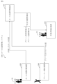
- FIG. 2 is a diagram showing an example of the configuration of a hole position management device according to the first embodiment.
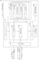
- FIG. 2 is a diagram showing a configuration example of a worker terminal device according to the first embodiment;
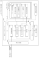
- 1 is a diagram showing an example of the configuration of a player terminal device according to the first embodiment;
- 5A and 5B are diagrams showing a display example of a worker support screen according to the first embodiment;
- 5A and 5B are diagrams showing an example of a notification method in the notification process according to the first embodiment;
- FIG. 13 is a diagram showing a display example of a worker support screen according to a modification of the first embodiment.
- FIG. 11 is a diagram showing a configuration example of a worker terminal device according to a second embodiment.
- FIG. 11 is a diagram showing an example of the configuration of a player terminal device according to the second embodiment.
- FIG. 13 is a diagram showing a display example of a worker support screen according to the second embodiment.
- FIG. 13 is a diagram showing a display example of a player support screen according to the second embodiment.
- FIG. 11 is a diagram showing a configuration example of a worker terminal device according to a second embodiment.
- FIG. 11 is a diagram showing an example of the configuration of a player terminal device according to the second embodiment.
- FIG. 13 is a diagram showing a display example of a worker support screen according to the second embodiment.
- FIG. 13 is a diagram showing a display
- FIG. 13 is a diagram showing a configuration example of a worker terminal device according to a third embodiment.
- FIG. 13 is a diagram showing a display example of a worker support screen according to the third embodiment.
- FIG. 1 is a diagram showing an example of the overall configuration of a hole position management system 500 according to the present embodiment.
- the hole position management system 500 is a system for supporting an operator 30 who mainly determines the hole position on the green of a golf course.
- the hole position is also called a pin position.
- the operator 30 who determines the hole position is also called a green keeper or a groundskeeper.
- the hole position management system 500 includes a hole position management device 100, an operator terminal device 200, and a player terminal device 300.
- the hole position management system 500 may also include a hole position measurement device 400.
- the hole position management device 100 is, for example, a server device.
- the hole position management device 100 may be realized by a cloud computer.
- the hole position management device 100 communicates with each of the worker terminal device 200, the player terminal device 300, and the hole position measurement device 400 via a network.
- the hole position management device 100 transmits decision support information 20 to the worker terminal device 200 to support the worker 30 who decides the hole position.
- the decision support information 20 will be described later.
- the worker terminal device 200 is a device that assists the worker 30 in determining the hole position on the green.
- the worker terminal device 200 is carried by the worker 30 and used by the worker 30.
- the worker terminal device 200 is a portable information processing device such as a smartphone, mobile phone, tablet terminal, or wearable terminal.
- the player terminal device 300 is a device that supports a player who uses the green.
- the player terminal device 300 is used by a player.
- the player terminal device 300 is a portable information processing device such as a smartphone, mobile phone, tablet device, or wearable device.
- the player terminal device 300 may be an information processing device mounted on a course traveling vehicle that automatically drives itself around a golf course based on a driving route.
- a player who uses the green is a golfer who plays golf on a golf course.
- the hole position measuring device 400 is a device that is carried when a new hole is constructed at the hole position determined by the worker 30.
- the hole position measuring device 400 is a device that measures the position of the newly constructed hole. Note that this embodiment can be realized without the hole position measuring device 400.
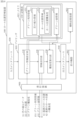
- FIG. 2 is a diagram showing an example of the configuration of the hall position management device 100 according to the present embodiment.
- FIG. 3 is a diagram showing an example of the configuration of the worker terminal device 200 according to the present embodiment.
- FIG. 4 is a diagram showing an example of the configuration of a player terminal device 300 according to this embodiment.
- Each of the hole position management device 100, the worker terminal device 200, and the player terminal device 300 is a computer. In the following, each of the hole position management device 100, the worker terminal device 200, and the player terminal device 300 may be referred to as each device of the hole position management system 500.
- Each device in the hole position management system 500 includes a processor 910, as well as other hardware such as a memory 921, an auxiliary storage device 922, an input interface 930, an output interface 940, and a communication device 950.
- the processor 910 is connected to the other hardware via signal lines and controls the other hardware.
- the hardware of each device in the hall position management system 500 is given the same symbol, but it is self-evident that each device in the hall position management system 500 has its own individual hardware.
- the hole position management device 100 comprises, as functional elements, a green information setting unit 110, an information transmission unit 120, and a memory unit 150.
- the memory unit 150 stores green usage information 151 and green surface information 152.
- the green usage information 151 includes turf damage information 511 and hole position information 512.
- the worker terminal device 200 has, as its functional elements, an information acquisition unit 210, a support information display unit 220, a determined position reception unit 230, a notification unit 240, and a memory unit 250.
- the memory unit 250 stores green usage information 151, green surface information 152, and determined position information 251.
- the player terminal device 300 has the following functional elements: a play information acquisition unit 310, a play information display unit 320, and a memory unit 350.
- the following describes the hardware using the hall position management device 100 as an example.
- the same explanation as for the hall position management device 100 can be applied to the hardware of other devices.
- the functions of the green information setting unit 110 and the information transmission unit 120 are realized by software.
- the storage unit 150 is provided in the memory 921. Note that the storage unit 150 may be provided in the auxiliary storage device 922, or may be provided separately in the memory 921 and the auxiliary storage device 922.
- the processor 910 is a device that executes a hole position management program.
- the hole position management program is a program that realizes the functions of each device in the hole position management system 500.
- the processor 910 is an IC that performs arithmetic processing. Specific examples of the processor 910 are a CPU, a DSP, and a GPU.
- IC is an abbreviation for Integrated Circuit.
- CPU is an abbreviation for Central Processing Unit.
- DSP is an abbreviation for Digital Signal Processor.
- GPU is an abbreviation for Graphics Processing Unit.
- the memory 921 is a storage device that temporarily stores data. Specific examples of the memory 921 are SRAM and DRAM. SRAM is an abbreviation for Static Random Access Memory. DRAM is an abbreviation for Dynamic Random Access Memory.
- the auxiliary storage device 922 is a storage device that stores data. A specific example of the auxiliary storage device 922 is a HDD.
- the auxiliary storage device 922 may also be a portable storage medium such as an SD (registered trademark) memory card, a CF, a NAND flash, a flexible disk, an optical disk, a compact disk, a Blu-ray (registered trademark) disk, or a DVD. Note that HDD is an abbreviation for Hard Disk Drive. SD (registered trademark) is an abbreviation for Secure Digital. CF is an abbreviation for CompactFlash (registered trademark). DVD is an abbreviation for Digital Versatile Disk.
- the input interface 930 is a port that is connected to an input device such as a mouse, keyboard, or touch panel. Specifically, the input interface 930 is a USB terminal. The input interface 930 may also be a port that is connected to a LAN.
- USB is an abbreviation for Universal Serial Bus.
- LAN is an abbreviation for Local Area Network.
- the output interface 940 is a port to which a cable of an output device, which is a display device 941 such as a display, is connected.
- the output interface 940 is a USB terminal or an HDMI (registered trademark) terminal.
- the display is an LCD.
- the output interface 940 is also called a display interface.
- HDMI (registered trademark) is an abbreviation for High Definition Multimedia Interface.
- LCD is an abbreviation for Liquid Crystal Display.
- the communication device 950 has a receiver and a transmitter.
- the communication device 950 is connected to a communication network such as a LAN, the Internet, a telephone line, or Wi-Fi (registered trademark).
- the communication device 950 is a communication chip or NIC.
- NIC is an abbreviation for Network Interface Card.
- the hole position management program is executed in each device of the hole position management system 500.
- the hole position management program is executed, for example, in the hole position management device 100.
- the hole position management program is loaded into the processor 910 and executed by the processor 910.
- Memory 921 stores not only the hole position management program but also the OS.
- OS is an abbreviation for Operating System.
- the processor 910 executes the hole position management program while executing the OS.
- the hole position management program and the OS may be stored in the auxiliary storage device 922.
- the hole position management program and the OS stored in the auxiliary storage device 922 are loaded into the memory 921 and executed by the processor 910. Note that part or all of the hole position management program may be incorporated into the OS.
- Each device of the hole position management system 500 may have multiple processors that replace the processor 910. These multiple processors share the task of executing the hole position management program.
- Each processor is a device that executes the hole position management program in the same way as the processor 910.
- the data, information, signal values and variable values used, processed or output by the hole position management program are stored in memory 921, auxiliary storage device 922, or in a register or cache memory within processor 910.
- each part of green information setting unit 110 and information transmission unit 120 may be read as a "circuit,”"step,”"procedure,””process," or “circuitry.”
- the hole position management program causes a computer to execute a green information setting process and an information transmission process.
- the "processing" of the green information setting process and the information transmission process may be read as a "program,””programproduct,””computer-readable storage medium storing a program,” or "computer-readable recording medium recording a program.”
- the hole position management method is carried out by each device of the hole position management system 500 executing a hole position management program.
- the hole position management program may be provided by being stored in a computer-readable recording medium. Also, the hole position management program may be provided as a program product.
- each device in hole position management system 500 corresponds to a hole position management method.
- the program that realizes the operation of each device in hole position management system 500 corresponds to a hole position management program.
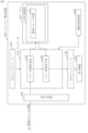
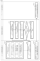
- FIG. 5 is a flow diagram showing the operation of each device in the hole position management system 500 according to this embodiment.
- the memory unit 150 of the hole position management device 100 stores green usage information 151 indicating the usage status of the greens in the golf course, and green surface information 152 including map information of the green surfaces.
- step S ⁇ b>101 the green information setting unit 110 of the hole position management device 100 sets the green usage information 151 and the green surface information 152 in the memory unit 150 .
- the green usage information 151 includes turf damage information 511 that indicates damaged areas of the turf on the green.
- the green information setting unit 110 acquires turf damage data 31 that indicates damaged areas of the turf on the green, and sets the damaged areas of the turf on the green as turf damage information 511 in the green usage information 151 .
- the green information setting unit 110 receives position information of damaged grass areas on the green input by a worker such as a greenkeeper as turf damage data 31.
- the green information setting unit 110 sets the turf damage data 31 in the green usage information 151 as turf damage information 511.
- a drone used to measure a golf course, or a PMV or AMR used to support a player may acquire information about damaged areas of the grass on the green and transmit it to the hole position management device 100.
- Such equipment such as a drone, PMV, or AMR, is equipped with a camera. Based on an image of the green captured by the camera, an operator may determine areas of damaged grass and transmit the data to the hole position management device 100 as grass damage data 31. Alternatively, based on an image of the green captured by the camera, the green information setting unit 110 may automatically determine areas of damaged grass using a method such as machine learning and acquire the data as grass damage data 31.
- a PMV is an autonomous vehicle capable of carrying a person on board. PMV is an abbreviation of Personal Mobility Vehicle.
- An AMR is an autonomous vehicle that does not carry a person on board.
- AMR is an abbreviation of Autonomous Mobile Robot.
- a PMV or AMR has a function of an autonomously traveling cart and various support functions for supporting a golfer.
- the green usage information 151 also includes hole position information 512 that indicates the past hole positions on the green.
- the green information setting unit 110 acquires a new hole position on the green and sets the new hole position in the green utilization information 151. In this manner, the green information setting unit 110 accumulates the hole position in the green utilization information 151 every time a new hole position is formed. As a result, hole position information 512 indicating the past hole position on the green is set in the green utilization information 151.
- the new hole position on the green is measured by a hole position measuring device 400 carried by a worker 30 such as a greenkeeper when constructing a new hole. After completing the drilling work at the new hole position, the worker 30 installs the hole position measurement device 400 in the new hole.
- the hole position measurement device 400 automatically measures the new hole position and transmits the measured new hole position to the hole position management device 100. In this way, the new hole position may be automatically transmitted from the hole position measurement device 400, or the new hole position, which is the measurement result, may be input by the operator 30 to the hole position management device 100.
- the green surface information 152 includes map information of the green.
- the map information of the green included in the green surface information 152 is preferably a three-dimensional map, but may also be a two-dimensional map.
- the green information setting unit 110 acquires the difficulty level corresponding to the position information on the green surface as the green difficulty level 33. Specifically, the green information setting unit 110 acquires the green difficulty level 33 input by an operator such as a greenkeeper. The green difficulty level 33 is associated with the position information on the green surface. The green information setting unit 110 sets the green difficulty level 33 in the green surface information 152.
- the green information setting unit 110 may also automatically set the green difficulty level 33 using the elevation of the three-dimensional map of the green. For example, the green information setting unit 110 determines the shape of the green surface based on the elevation of the three-dimensional map of the green. The hole position management device 100 is assumed to store in advance the green difficulty level corresponding to the shape of the green surface. The green information setting unit 110 may then obtain the green difficulty level 33 according to the determined shape of the green surface and set it in the green surface information 152. In this way, a high green difficulty level 33 is automatically set for areas of the green surface where putting is highly difficult, such as areas on the downhill slope after mounting or areas that are shaped like a mortar. A low green difficulty level 33 is automatically set for areas of the green surface where putting is relatively easy, such as areas on the flat surface or areas on a gentle uphill slope.
- the process of setting the green usage information 151 and the process of setting the green surface information 152 may be performed at any timing. For example, damaged areas of the grass may be set every specified number of days. Also, new hole positions may be set before the golf course opens each day, or after the golf course closes each day. The green difficulty level may be reset every specified period, such as every two weeks or one month. Also, if there are multiple greens on a course, it may be reset every time the green in use is changed.
- step S ⁇ b>102 the information transmitting unit 120 of the hole position management device 100 transmits the green utilization information 151 and the green surface information 152 to the worker terminal device 200 .
- the information transmission process for transmitting the green utilization information 151 and the green surface information 152 is performed periodically, for example, once every morning. Alternatively, the information transmission process may be performed irregularly, such that the green utilization information 151 and the green surface information 152 are transmitted whenever new information is updated.
- the worker terminal device 200 is a device that assists a worker in determining the hole position on the green of a golf course.
- step S201 the information acquisition unit 210 of the worker terminal device 200 acquires the green usage information 151 and the green surface information 152. Specifically, the information acquisition unit 210 receives the green usage information 151 and the green surface information 152 transmitted from the hole position management device 100, and stores them in the memory unit 250.
- step S202 the support information display unit 220 of the worker terminal device 200 uses the green utilization information 151 and the green surface information 152 to display the worker support screen 270 on the display device 941.
- the green utilization status is superimposed on a map of the green.
- the usage status of the green refers to information such as damaged areas of the grass on the green, past hole positions, or the difficulty of the green corresponding to position information on the green surface, for example.
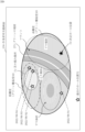
- FIG. 6 is a diagram showing a display example of the worker support screen 270 according to this embodiment.
- the support information display unit 220 displays the damaged areas of the grass on the green by superimposing them on the green map 271.
- the support information display unit 220 displays the damaged areas of the grass 71 on the green by superimposing them on the green map 271, using the grass damage information 511 included in the green usage information 151.
- a damaged area 71 of the grass is superimposed on a map 271 of the green.
- Green map 271 shows the shape of the green. If green map 271 is a three-dimensional map, the green shape is shown in three dimensions. If green map 271 is a two-dimensional map, shapes such as a cone shape, a mount, a downward slope, and an upward slope are displayed.
- the support information display unit 220 also displays past hole positions 72 on the green, superimposed on the green map 271.
- the support information display unit 220 uses hole position information 512 accumulated in the green usage information 151 to display past hole positions 72 superimposed on the green map 271.
- the support information display unit 220 may extract and display past hole positions 72 corresponding to a predetermined period from the past hole positions included in the hole position information 512.
- the support information display unit 220 may receive a designation of the period to be displayed from the worker 30, such as the most recent week or the most recent two weeks. In the example of FIG. 6, four past hole positions 72 are superimposed on a map 271 of the green along with their dates.
- the support information display unit 220 also displays the green difficulty level 33 superimposed on the map 271 of the green.
- the support information display unit 220 displays the green difficulty level 33, which is the difficulty level corresponding to the position information of the green included in the green surface information 152, superimposed on the map 271 of the green. 6, an area surrounded by a dotted line, which has a high green difficulty level 33, is superimposed on the green map 271. Also, an area surrounded by a dashed dotted line, which has a low green difficulty level 33, is superimposed on the green map 271.
- step S203 the determined position receiving unit 230 of the worker terminal device 200 receives the hole position determined by the worker 30 as the determined hole position 73 .
- the worker 30 refers to the worker support screen 270 displayed on the display device 941 of the worker terminal device 200 and determines the hole position of a hole to be newly installed on the green as the determined hole position 73 .
- the worker 30 determines a new hole location based on the relationship between the condition of the grass, the recent hole location, and the green difficulty level estimated from the green surface shape while referring to the worker support screen 270. The worker 30 then specifies the new hole location on the green map 271. If the green difficulty level 33 is not displayed, the worker 30 estimates the difficulty level of the hole location from the green surface shape. In the example of Figure 6, the worker 30 determines a hole position just before the green in an area with a high green difficulty level 33, and specifies the determined hole position 73 on the worker support screen 270 via an input device such as a touch panel.
- the notification section 240 of the worker terminal device 200 When approaching a determined hole position 73 that is the hole position determined by the worker 30 , the notification section 240 of the worker terminal device 200 notifies the worker 30 that the worker 30 is approaching the determined hole position 73 .
- the notification unit 240 determines whether or not the worker terminal device 200 is approaching the determined hole position 73. Specifically, the notification unit 240 acquires its own position using a position information determination function such as a GPS mounted on the worker terminal device 200. GPS is an abbreviation for Global Positioning System.
- the notification unit 240 determines whether or not the self-position is approaching the determined hole position 73 based on whether or not the self-position is within a predetermined distance range of the determined hole position 73.
- the predetermined distance can be set to a desired distance such as 1.5 m, 1 m, or 80 cm. If it is determined that the ball is approaching the decision hole position 73, the process proceeds to step S205.
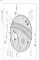
- FIG. 7 is a diagram showing an example of a notification method in the notification process according to the present embodiment.
- the notification unit 240 notifies the player that his/her own position is approaching the determined hole position 73 using the output device.
- the notification unit 240 may display the own position 74 on the worker support screen 270, and may change color or blink when the own position 74 comes within a predetermined distance range of the determined hole position 73.
- the notification unit 240 may output a notification voice such as "You are within a radius of 1 m from the determined hole position" from a speaker mounted on the worker terminal device 200. Any notification method may be adopted as long as it can notify the worker 30 that he or she is approaching the determined hole position 73.
- the worker 30 refers to the worker support screen 270 and determines the hole position where the new hole will actually be created. The worker 30 then creates the new hole position at or near the determined hole position 73.
- the hole position management device 100 receives the hole position 32 from the hole position measurement device 400 or an operator such as a greenkeeper who has measured the hole position.
- the information transmitting section 120 of the hole position management device 100 transmits the latest hole position 41 to the player terminal device 300.
- the latest hole position 41 is the hole position for the golfer on that day.
- step S301 the play information acquisition section 310 of the player terminal device 300 receives the latest hole position 41 from the hole position management device 100. Then, the play information display section 320 of the player terminal device 300 displays the latest hole position 41 on the display device of the player terminal device 300.
- the player terminal device 300 is a device that supports a player who uses the greens of a golf course. The player terminal device 300 has a function of assisting a golfer in planning a course strategy by providing the golfer with accurate information on the hole positions on the day of play.
- the worker 30 may determine the past hole positions 72 and the green difficulty level 33.
- any information that can be useful to the worker 30 in determining the hole position may be displayed on the worker support screen 270.
- FIG. 8 is a diagram showing a display example of a worker support screen 270 according to a modified example of the present embodiment.
- the green surface information 152 may include the surrounding conditions of the green.
- the green information setting unit 110 may set the surrounding conditions of the green in the green surface information 152.
- the green information setting unit 110 may set the surrounding conditions of the green inputted by the greenkeeper in the green surface information 152.
- the surrounding conditions of the green are defined as green surrounding information 75. 8, the difficulty level corresponding to the position information of the green changes depending on the surrounding conditions of the green.
- green surroundings information 75 such as bunkers, plants, or water hazards around the green is set in the green surface information 152.
- the operator 30 can determine the green difficulty level 33 while taking into consideration the green surroundings information 75 and use this information to determine a new hole position.
- the green information setting unit 110 may also automatically set the green difficulty level 33 by taking into consideration the elevation of the green on the three-dimensional map and the green surroundings information 75.
- each device in the hole position management system 500 are realized by software.
- the functions of each device in the hole position management system 500 may be realized by hardware.
- each device of the hole position management system 500 includes an electronic circuit 909 instead of a processor 910 .
- FIG. 9 is a diagram showing an example of the configuration of a hall position management device 100 according to a modified example of this embodiment.
- the hole position management device 100 will be described as an example, but the same applies to the operator terminal device 200 and the player terminal device 300.
- the electronic circuit 909 is a dedicated electronic circuit that realizes the functions of the green information setting unit 110 and the information transmission unit 120. Specifically, the electronic circuit 909 is a single circuit, a composite circuit, a programmed processor, a parallel programmed processor, a logic IC, a GA, an ASIC, or an FPGA.
- GA is an abbreviation for Gate Array.
- ASIC is an abbreviation for Application Specific Integrated Circuit.
- FPGA is an abbreviation for Field-Programmable Gate Array.
- the functions of the green information setting unit 110 and the information transmission unit 120 may be realized in a single electronic circuit, or may be distributed across multiple electronic circuits.
- some of the functions of the green information setting unit 110 and the information transmission unit 120 may be realized by electronic circuits, and the remaining functions may be realized by software. Also, some or all of the functions of the green information setting unit 110 and the information transmission unit 120 may be realized by firmware.
- Each of the processor and electronic circuitry is also called processing circuitry.
- the functions of the green information setting unit 110 and the information transmission unit 120 are realized by the processing circuitry.
- a two-dimensional or three-dimensional map that visualizes the green surface shape or turf condition is displayed on the worker support screen. Furthermore, past hole positions can be mapped and displayed on the worker support screen. In this way, by displaying the green usage status superimposed on the green map, the worker can take into account the turf condition, past hole positions, or green difficulty. Therefore, according to the hole position management system of this embodiment, it is possible to improve the efficiency of support when determining hole positions.
- the hole position management system makes it possible to manage and utilize information on hole positions that change daily, which can lead to improved maintenance of golf course grass and improved golfer satisfaction.
- Embodiment 2 differences from and additions to the first embodiment will be mainly described.
- components having the same functions as those in the first embodiment are given the same reference numerals, and the description thereof will be omitted.
- FIG. 10 is a diagram showing an example of the configuration of a hole position management device 100 according to this embodiment.
- FIG. 11 is a diagram showing an example of the configuration of the worker terminal device 200 according to the present embodiment.
- FIG. 12 is a diagram showing an example of the configuration of a player terminal device 300 according to this embodiment.
- the hole position management device 100 includes a difficulty level calculation unit 130 in addition to the functional elements described in the first embodiment. Also, the hole position information 512 stored in the storage unit 150 includes a hole position difficulty level 34. In the operator terminal device 200 , in addition to the functional elements described in the first embodiment, a hole position difficulty level 34 is stored in the hole position information 512 stored in the storage unit 150 . In the player terminal device 300, the play information acquisition section 310 acquires the difficulty level 42 of the latest hole position in addition to the latest hole position 41 explained in the first embodiment.
- FIG. 13 is a flow diagram showing the operation of each device in the hole position management system 500 according to this embodiment.
- step S101a the green information setting unit 110 sets the green usage information 151 and the green surface information 152.
- a hole position difficulty level 34 is set for each hole position.
- the green information setting unit 110 sets the play status on the green for each past hole position on the green as the green play status in the green usage information 151.
- the green play status is, for example, green score information, which is the number of strokes since the ball landed on the green, or the green play time on the green.
- the green information setting unit 110 sets green score information, which is the number of strokes since the ball landed on the green, and the green play time on the green for each past hole position on the green, in the green usage information 151. Specifically, the following applies:
- the green score information may be obtained, for example, by a device such as a PMV or an AMR used to support a player.
- the device such as a PMV or an AMR obtains the number of strokes from when the ball lands on the green to when it goes in the cup, and transmits the information to the hole position management device 100. More specifically, the number of strokes may be estimated by analyzing images of the golfer's play obtained by an image sensor mounted on the device such as a PMV or an AMR.
- the player terminal device 300 which is a wearable device worn by the golfer, may obtain the number of strokes and transmit it to the hole position management device 100 .
- the player may input the number of strokes from when the ball lands on the green to when it goes in the cup into the player terminal device 300 , and the player terminal device 300 may transmit this number of strokes to the hole position management device 100 .
- the number of strokes from the approach to the cup-in may be used as the green score information.
- the green play time may be acquired by a device such as a PMV or AMR used to support the player, and transmitted to the hole position management device 100. More specifically, the time that a device such as a PMV or AMR is parked at the cart stop position on the green may be estimated as the green play time, and transmitted to the hole position management device 100.
- the difficulty calculation unit 130 of the hole position management device 100 calculates the difficulty level for each past hole position on the green as hole position difficulty level 34 based on the green score information and green play time.
- the difficulty calculation unit 130 sets the hole position difficulty level 34, which is the difficulty level for each past hole position, in the green usage information 151.
- the conditions around the green may be taken into consideration when calculating the hole location difficulty level 34 .
- green surroundings information 75 such as guard bunkers, standing trees, and OB stakes are set in the green surface information 152.
- the difficulty calculation unit 130 may use this green surroundings information 75 in calculating the hole position difficulty 34. For example, if there is a bunker behind the position of the cup, there is a higher possibility that a strong putt will cause the ball to roll into the bunker behind, increasing the psychological difficulty. Also, if there is a bunker in front of the cup, the difficulty level increases because the ball cannot be rolled onto the green.
- the information transmitting unit 120 includes the hole position difficulty 34 in the green usage information 151. Therefore, the information acquiring unit 210 acquires the hole position difficulty 34 for each past hole position on the green, which is calculated based on the green score information and the green play time.
- step S202a the support information display unit 220 of the worker terminal device 200 uses the green utilization information 151 and the green surface information 152 to display the green utilization status superimposed on the green map 270.
- the operator support screen 270 displays a hole position difficulty level 34 in addition to the green usage status described in the first embodiment.
- FIG. 14 is a diagram showing a display example of a worker support screen 270 according to this embodiment.
- the support information display section 220 displays the hole position difficulty level 34 for each past hole position 72 superimposed on a map 271 of the green.
- a hole location difficulty level 34 is displayed below the date of the past hole location.
- step S203 to step S204 are similar to those in the first embodiment.
- the worker 30 determines the determined hole position 73 while referring to the worker support screen 270 , and establishes a new hole position at or near the determined hole position 73 .
- step S103 a the information transmitting section 120 transmits to the player terminal device 300 the latest hole position 41 on the green and the difficulty level 42 of the latest hole position out of the hole position difficulty level 34 .
- step S301a the play information acquisition section 310 of the player terminal device 300 acquires the latest hole position 41 and the difficulty level 42 of the latest hole position.
- the play information display unit 320 generates a player support screen 370 in which the latest hole position 41 and the difficulty level 42 of the latest hole position are superimposed on a map 371 of the green, and displays it on the display device 941.
- FIG. 15 is a diagram showing a display example of a player support screen 370 according to this embodiment.
- the hole position difficulty level at the latest hole position and the average number of strokes per putt at the latest hole position are displayed in association with the hole position on the day of play.
- the average number of strokes per putt is displayed using the green score information set in the green usage information 151 described in the first embodiment.
- a message such as "Please enter your satisfaction level” may be displayed to prompt the golfer to input the level of satisfaction with the hole using the number of stars, etc. Use of the satisfaction level will be described in the third embodiment.
- the difficulty level calculation section 130 calculates a hole position difficulty level 34 for each past hole position on the green, based on the green score information and the green play time.
- the difficulty calculation unit 130 may calculate the hole position difficulty 34 from only the green score information.
- the difficulty calculation unit 130 may calculate the hole position difficulty 34 from only the green play time.
- the difficulty calculation unit 130 may combine the green score information, the green play time, and the green surroundings information in any way to calculate the hole position difficulty 34.
- the hole position difficulty for each hole position can be displayed on the operator terminal device in addition to the green difficulty derived from the green shape, allowing the operator to determine a new hole position using more information about the green.
- the player terminal device can display the hole position difficulty and the number of putting strokes for each hole position in addition to the green difficulty. Therefore, by providing the golfer with accurate information on the hole positions on the day of play, it is possible to assist the golfer in planning a course strategy.
- Embodiment 3 differences from the first and second embodiments and additional features to the first and second embodiments will be mainly described.
- components having the same functions as those in the first and second embodiments are given the same reference numerals, and the description thereof will be omitted.
- FIG. 16 is a diagram showing an example of the configuration of a hall position management device 100 according to this embodiment.
- FIG. 17 is a diagram showing an example of the configuration of a worker terminal device 200 according to this embodiment.
- Hall position management device 100 includes a candidate selection unit 140 in addition to the functional elements described in embodiment 1. Also, a storage unit 150 stores hall position candidates 153. In the worker terminal device 200, the information acquisition unit 210 receives the hole position candidates 153. Furthermore, the memory unit 250 stores the hole position candidates 153.
- FIG. 18 is a flow diagram showing the operation of each device in the hole position management system 500 according to this embodiment.
- step S1011 is performed after step S101a.
- step S1011 the candidate selection unit 140 of the hole position management device 100 selects a candidate for a new hole position on the green as a hole position candidate 153 based on the green usage information 151 and the green surface information 152.
- the candidate selection unit 140 selects the hole position candidate 153 based on the condition of the turf, information linking play information with hole positions, and past hole positions.
- the candidate selection unit 140 selects hole location candidates 153 using all or some of the following information: Grass damage information 511 included in the green usage information 151. - Past hole locations and hole location difficulty levels 34 included in the hole location information 512. The shape of the green surface and the green difficulty level 33 included in the green surface information 152 .
- the candidate selection unit 140 selects the hole location candidates 153 using all or some of the following indicators: - Locations where the grass is damaged will be excluded from the candidates. - Eliminate areas with low golfer satisfaction. - Avoid areas with high difficulty. For example, if there is a hole position where the median score of users is 6 strokes or more on a par 3 hole, avoid that area. - In order to improve turnover rate, avoid areas where playing time exceeds a certain value. - Select and suggest hole locations that will give golfers the highest level of satisfaction. - Place the ball away from the most recent hole location.
- the green information setting section 110 acquires the player's degree of satisfaction with the golf course, and sets the degree of satisfaction in the green usage information 151 .
- the candidate selection unit 140 calculates the difficulty level and average play time for each hole location candidate 153.
- the information transmission unit 120 transmits to the operator terminal device 200 the difficulty level, average play time, and satisfaction level associated with each hole location candidate 153.
- the information acquisition unit 210 acquires the degree of difficulty, average play time, and player satisfaction level corresponding to the hole location candidate 153.
- the support information display unit 220 displays the degree of difficulty, average play time, and player satisfaction level superimposed on the map 271 of the green together with the hole location candidate 153. Specifically, the following applies:
- the golfer's satisfaction level may be obtained by having the golfer input his/her satisfaction level for each hole. For example, when inputting a score for each course into the player terminal device 300, the golfer inputs his/her satisfaction level for that course as "high, medium, low.” Alternatively, the golfer may input his/her satisfaction level for all courses as "high, medium, low” when finishing a hole.
- the player terminal device 300 transmits the golfer's satisfaction level to the hole position management device 100.
- the green information setting unit 110 receives the golfer's satisfaction level and sets the golfer's satisfaction level in the green usage information 151. In this way, the golfer's satisfaction level can be obtained for each hole position on that day. If the golfer cannot input a satisfaction level for each hole, the green information setting unit 110 may record the same satisfaction level for multiple hole positions.
- the candidate selection unit 140 can determine areas where golfers have high or low satisfaction based on past hole locations and golfer satisfaction.
- the candidate selection unit 140 selects a plurality of hole location candidates 153.
- the candidate selection unit 140 calculates the difficulty level and average play time for each hole location candidate 153.
- the candidate selection unit 140 associates the difficulty level, average play time, and golfer satisfaction level for each hole position candidate 153 and transmits them to the operator terminal device 200.
- step S102b the information transmission unit 120 transmits the green usage information 151, green surface information 152, and hole position candidates 153 to the worker terminal device 200.
- step S201b the information acquisition unit 210 acquires the green usage information 151, the green surface information 152, and the hole position candidate 153. Specifically, the information acquisition unit 210 receives the green usage information 151, the green surface information 152, and the hole position candidate 153 transmitted from the hole position management device 100, and stores them in the memory unit 250.
- step S202a is the same as in embodiment 2.
- step S2021 the support information display unit 220 displays the hole position candidates 153 superimposed on the map 271 of the green.
- FIG. 19 is a diagram showing a display example of a worker support screen 270 according to this embodiment. 19, three hole position candidates 153 are superimposed on a map 271 of the green displayed on the operator support screen 270. The degree of difficulty, the degree of satisfaction, and the playing time are displayed for each hole position candidate 153.
- the support information display unit 220 uses the difficulty level, average play time, and golfer satisfaction level associated with each hole location candidate 153 to display the difficulty level, satisfaction level, and play time for each hole location candidate 153.
- the display method may be to display the hole location candidates 153 with high satisfaction level in red and the hole location candidates 153 with low satisfaction level in blue.
- the hole location candidates 153 with high satisfaction level may be displayed by different shapes, such as a star or double circle, and the hole location candidates 153 with low satisfaction level in a triangle or cross.
- the difficulty level is displayed by different colors, it is preferable to display the difficulty level, satisfaction level, and play time in a way that is easy for the operator 30 to understand, such as by displaying the satisfaction level by different shapes.
- the hole position management system can automatically display hole position candidates, providing more efficient information to the operator.
- the degree of difficulty, satisfaction, and playing time can be displayed for each hole position candidate, allowing the operator to select the most appropriate hole position from among multiple hole position candidates.
- each part of each device in the hole position management system has been described as an independent functional block.
- the configuration of each device in the hole position management system does not have to be as in the above-mentioned embodiments.
- the functional blocks of each device in the hole position management system may have any configuration as long as they can realize the functions described in the above-mentioned embodiments.
- each device in the hole position management system may not be a single device, but may be a system made up of multiple devices.
- first to third embodiments may be implemented.
- one part of these embodiments may be implemented.
- any combination of these embodiments may be implemented as a whole or in part. That is, in the first to third embodiments, the embodiments can be freely combined, any of the components in each embodiment can be modified, or any of the components in each embodiment can be omitted.
Landscapes
- Health & Medical Sciences (AREA)
- General Health & Medical Sciences (AREA)
- Physical Education & Sports Medicine (AREA)
- General Factory Administration (AREA)
- Management, Administration, Business Operations System, And Electronic Commerce (AREA)
Abstract
ホール位置管理装置(100)は、ゴルフコースにおけるグリーンの利用状況を表すグリーン利用情報(151)と、グリーンのグリーン面の地図情報を含むグリーン面情報(152)とを記憶する記憶部(150)を備える。また、ホール位置管理装置(100)は、情報送信部(120)を備える。情報送信部(120)は、作業者によるグリーンにおけるホール位置の決定を支援する作業者端末装置に、グリーン利用情報(151)およびグリーン面情報(152)を送信する。
Description
本開示は、ホール位置管理装置、作業者端末装置、プレーヤー端末装置、ホール位置管理方法、およびホール位置管理プログラムに関する。特に、ゴルフコースのグリーンにおけるホール位置の決定を支援するホール位置管理装置、作業者端末装置、プレーヤー端末装置、ホール位置管理方法、およびホール位置管理プログラムに関する。
ゴルフ場において、グリーン上のカップの位置であるホール位置は、以下の理由で基本的に毎日変更される。グリーン上のホール位置はピンポジションともいう。
・ホールのまわりの芝は日が経つうちに擦れてくる。
・ホール位置が毎回同じだとプレーが退屈になる。
・ホール位置によって難易度が変わる。
・ホールのまわりの芝は日が経つうちに擦れてくる。
・ホール位置が毎回同じだとプレーが退屈になる。
・ホール位置によって難易度が変わる。
このような理由から、ホール位置を正確に管理することは、ゴルフ場の芝の維持管理、ゴルファーのゴルフ場に対する満足度、およびゴルファーのプレー戦略立案といった観点から重要である。
現在は、熟練の作業者が、ゴルフ場の芝の維持管理、ゴルファーのゴルフ場に対する満足度、およびゴルファーのプレー戦略立案といった観点を考慮し、ホール位置を決定している。
現在は、熟練の作業者が、ゴルフ場の芝の維持管理、ゴルファーのゴルフ場に対する満足度、およびゴルファーのプレー戦略立案といった観点を考慮し、ホール位置を決定している。
特許文献1は、グリーン上のカップに装着することで、カップ位置を高精度に検出する位置検出装置が開示されている。
特許文献1の位置検出装置は、ゴルファーがプレーの戦略を立てるために重要なホール位置を、予め高精度に検出する装置である。しかしながら、特許文献1には、高精度に検出されたホール位置を、ホール位置の決定の支援に活用する仕組みは開示されていない。
現状では、グリーン上のホール位置の決定はグリーンキーパーといった作業者に委ねられていることが多い。よって、経験の浅いグリーンキーパーの場合にホール位置の決定が適切に行われないおそれがあるという課題がある。
現状では、グリーン上のホール位置の決定はグリーンキーパーといった作業者に委ねられていることが多い。よって、経験の浅いグリーンキーパーの場合にホール位置の決定が適切に行われないおそれがあるという課題がある。
本開示は、グリーンの利用状況を活用することで、グリーンにおけるホール位置の決定について作業者を支援する支援効率を向上させることを目的とする。
本開示に係るホール位置管理装置は、
ゴルフコースにおけるグリーンの利用状況を表すグリーン利用情報と、前記グリーンのグリーン面の地図情報を含むグリーン面情報とを記憶する記憶部と、
作業者による前記グリーンにおけるホール位置の決定を支援する作業者端末装置に、前記グリーン利用情報および前記グリーン面情報を送信する情報送信部と
を備える。
ゴルフコースにおけるグリーンの利用状況を表すグリーン利用情報と、前記グリーンのグリーン面の地図情報を含むグリーン面情報とを記憶する記憶部と、
作業者による前記グリーンにおけるホール位置の決定を支援する作業者端末装置に、前記グリーン利用情報および前記グリーン面情報を送信する情報送信部と
を備える。
本開示に係るホール位置管理装置では、情報送信部が、作業者によるグリーンにおけるホール位置の決定を支援する作業者端末装置に、グリーン利用情報およびグリーン面情報を送信する。よって、本開示に係るホール位置管理装置によれば、グリーン利用情報およびグリーン面情報といったグリーンの利用状況を活用することで、グリーンにおけるホール位置の決定について作業者を支援する支援効率を向上させることができる。
以下、本実施の形態について、図を用いて説明する。各図中、同一または相当する部分には、同一符号を付している。実施の形態の説明において、同一または相当する部分については、説明を適宜省略または簡略化する。図中の矢印はデータの流れまたは処理の流れを主に示している。また、以下の図では各構成部材の大きさの関係が実際のものとは異なる場合がある。また、実施の形態の説明において、上、下、左、右、前、後、表、裏といった向きあるいは位置が示されている場合がある。これらの表記は、説明の便宜上の記載であり、装置、器具、あるいは部品などの配置、方向および向きを限定するものではない。
実施の形態1.
***構成の説明***
図1は、本実施の形態に係るホール位置管理システム500の全体構成例を示す図である。
ホール位置管理システム500は、ゴルフコースにおけるグリーンにおいて、主に、ホール位置を決定する作業者30を支援するためのシステムである。ホール位置はピンポジションともいう。ホール位置を決定する作業者30は、グリーンキーパー、あるいはグラウンドキーパーとも呼ばれる。
***構成の説明***
図1は、本実施の形態に係るホール位置管理システム500の全体構成例を示す図である。
ホール位置管理システム500は、ゴルフコースにおけるグリーンにおいて、主に、ホール位置を決定する作業者30を支援するためのシステムである。ホール位置はピンポジションともいう。ホール位置を決定する作業者30は、グリーンキーパー、あるいはグラウンドキーパーとも呼ばれる。
ホール位置管理システム500は、ホール位置管理装置100、作業者端末装置200、およびプレーヤー端末装置300を備える。また、ホール位置管理システム500は、ホール位置計測装置400を備えていてもよい。
ホール位置管理装置100は、例えばサーバ装置である。ホール位置管理装置100は、クラウドコンピュータにより実現されてもよい。ホール位置管理装置100は、作業者端末装置200、プレーヤー端末装置300、およびホール位置計測装置400の各々と、ネットワークを介して通信する。ホール位置管理装置100は、ホール位置を決定する作業者30を支援するための決定支援情報20を作業者端末装置200に送信する。決定支援情報20については後述する。
作業者端末装置200は、作業者30によるグリーンにおけるホール位置の決定を支援する装置である。作業者端末装置200は、作業者30により携行され、作業者30により利用される。作業者端末装置200は、具体的には、スマートフォン、携帯電話、タブレット端末、あるいはウェアブル端末といった携帯可能な情報処理装置である。
プレーヤー端末装置300は、グリーンを利用するプレーヤーを支援する装置である。プレーヤー端末装置300は、プレーヤーにより利用される。具体的には、プレーヤー端末装置300は、スマートフォン、携帯電話、タブレット端末、あるいはウェアブル端末といった携帯可能な情報処理装置である。あるいは、プレーヤー端末装置300は、走行経路に基づいてゴルフコースを自動運転するコース走行車両に搭載された情報処理装置でもよい。
グリーンを利用するプレーヤーは、ゴルフコースにおいてゴルフのプレーをするゴルファーである。
グリーンを利用するプレーヤーは、ゴルフコースにおいてゴルフのプレーをするゴルファーである。
ホール位置計測装置400は、作業者30により決定されたホール位置にホールを新設する際に携行される装置である。ホール位置計測装置400は、新たに新設したホールの位置を計測する装置である。なお、ホール位置計測装置400は無くても本実施の形態は実現可能である。
図2は、本実施の形態に係るホール位置管理装置100の構成例を示す図である。
図3は、本実施の形態に係る作業者端末装置200の構成例を示す図である。
図4は、本実施の形態に係るプレーヤー端末装置300の構成例を示す図である。
ホール位置管理装置100、作業者端末装置200、およびプレーヤー端末装置300の各装置は、コンピュータである。以下において、ホール位置管理装置100、作業者端末装置200、およびプレーヤー端末装置300の各装置を、ホール位置管理システム500の各装置と呼ぶ場合がある。
図3は、本実施の形態に係る作業者端末装置200の構成例を示す図である。
図4は、本実施の形態に係るプレーヤー端末装置300の構成例を示す図である。
ホール位置管理装置100、作業者端末装置200、およびプレーヤー端末装置300の各装置は、コンピュータである。以下において、ホール位置管理装置100、作業者端末装置200、およびプレーヤー端末装置300の各装置を、ホール位置管理システム500の各装置と呼ぶ場合がある。
ホール位置管理システム500の各装置は、プロセッサ910を備えるとともに、メモリ921、補助記憶装置922、入力インタフェース930、出力インタフェース940、および通信装置950といった他のハードウェアを備える。プロセッサ910は、信号線を介して他のハードウェアと接続され、これら他のハードウェアを制御する。
なお、ここでは説明を簡単にするために、ホール位置管理システム500の各装置のハードウェアに同じ符号を付して説明しているが、ホール位置管理システム500の各装置は個別のハードウェアを備えていることは自明である。
なお、ここでは説明を簡単にするために、ホール位置管理システム500の各装置のハードウェアに同じ符号を付して説明しているが、ホール位置管理システム500の各装置は個別のハードウェアを備えていることは自明である。
ホール位置管理装置100は、機能要素として、グリーン情報設定部110と情報送信部120と記憶部150とを備える。記憶部150には、グリーン利用情報151とグリーン面情報152とが記憶される。グリーン利用情報151は、芝の傷み情報511とホール位置情報512を含む。
作業者端末装置200は、機能要素として、情報取得部210と支援情報表示部220と決定位置受付部230と報知部240と記憶部250とを備える。記憶部250には、グリーン利用情報151とグリーン面情報152と決定位置情報251が記憶される。
プレーヤー端末装置300は、機能要素として、プレー情報取得部310とプレー情報表示部320と記憶部350とを備える。
以下では、ホール位置管理装置100を例としてハードウェアの説明をする。他の装置においてもハードウェアについてホール位置管理装置100と同様の説明を適用することができる。
グリーン情報設定部110と情報送信部120の機能は、ソフトウェアにより実現される。記憶部150は、メモリ921に備えられる。なお、記憶部150は、補助記憶装置922に備えられていてもよいし、メモリ921と補助記憶装置922に分散して備えられていてもよい。
プロセッサ910は、ホール位置管理プログラムを実行する装置である。ホール位置管理プログラムは、ホール位置管理システム500の各装置の機能を実現するプログラムである。
プロセッサ910は、演算処理を行うICである。プロセッサ910の具体例は、CPU、DSP、GPUである。ICは、Integrated Circuitの略語である。CPUは、Central Processing Unitの略語である。DSPは、Digital Signal Processorの略語である。GPUは、Graphics Processing Unitの略語である。
プロセッサ910は、演算処理を行うICである。プロセッサ910の具体例は、CPU、DSP、GPUである。ICは、Integrated Circuitの略語である。CPUは、Central Processing Unitの略語である。DSPは、Digital Signal Processorの略語である。GPUは、Graphics Processing Unitの略語である。
メモリ921は、データを一時的に記憶する記憶装置である。メモリ921の具体例は、SRAM、あるいはDRAMである。SRAMは、Static Random Access Memoryの略語である。DRAMは、Dynamic Random Access Memoryの略語である。
補助記憶装置922は、データを保管する記憶装置である。補助記憶装置922の具体例は、HDDである。また、補助記憶装置922は、SD(登録商標)メモリカード、CF、NANDフラッシュ、フレキシブルディスク、光ディスク、コンパクトディスク、ブルーレイ(登録商標)ディスク、DVDといった可搬の記憶媒体であってもよい。なお、HDDは、Hard Disk Driveの略語である。SD(登録商標)は、Secure Digitalの略語である。CFは、CompactFlash(登録商標)の略語である。DVDは、Digital Versatile Diskの略語である。
補助記憶装置922は、データを保管する記憶装置である。補助記憶装置922の具体例は、HDDである。また、補助記憶装置922は、SD(登録商標)メモリカード、CF、NANDフラッシュ、フレキシブルディスク、光ディスク、コンパクトディスク、ブルーレイ(登録商標)ディスク、DVDといった可搬の記憶媒体であってもよい。なお、HDDは、Hard Disk Driveの略語である。SD(登録商標)は、Secure Digitalの略語である。CFは、CompactFlash(登録商標)の略語である。DVDは、Digital Versatile Diskの略語である。
入力インタフェース930は、マウス、キーボード、あるいはタッチパネルといった入力装置と接続されるポートである。入力インタフェース930は、具体的には、USB端子である。なお、入力インタフェース930は、LANと接続されるポートであってもよい。USBは、Universal Serial Busの略語である。LANは、Local Area Networkの略語である。
出力インタフェース940は、ディスプレイといった表示機器941である出力機器のケーブルが接続されるポートである。出力インタフェース940は、具体的には、USB端子またはHDMI(登録商標)端子である。ディスプレイは、具体的には、LCDである。出力インタフェース940は、表示器インタフェースともいう。HDMI(登録商標)は、High Definition Multimedia Interfaceの略語である。LCDは、Liquid Crystal Displayの略語である。
通信装置950は、レシーバとトランスミッタを有する。通信装置950は、LAN、インターネット、電話回線、あるいはWi-Fi(登録商標)といった通信網に接続している。通信装置950は、具体的には、通信チップまたはNICである。NICは、Network Interface Cardの略語である。
ホール位置管理プログラムは、ホール位置管理システム500の各装置に置いて実行される。ホール位置管理プログラムは、例えば、ホール位置管理装置100において実行される。ホール位置管理プログラムは、プロセッサ910に読み込まれ、プロセッサ910によって実行される。メモリ921には、ホール位置管理プログラムだけでなく、OSも記憶されている。OSは、Operating Systemの略語である。プロセッサ910は、OSを実行しながら、ホール位置管理プログラムを実行する。ホール位置管理プログラムおよびOSは、補助記憶装置922に記憶されていてもよい。補助記憶装置922に記憶されているホール位置管理プログラムおよびOSは、メモリ921にロードされ、プロセッサ910によって実行される。なお、ホール位置管理プログラムの一部または全部がOSに組み込まれていてもよい。
ホール位置管理システム500の各装置は、プロセッサ910を代替する複数のプロセッサを備えていてもよい。これら複数のプロセッサは、ホール位置管理プログラムの実行を分担する。それぞれのプロセッサは、プロセッサ910と同じように、ホール位置管理プログラムを実行する装置である。
ホール位置管理プログラムにより利用、処理または出力されるデータ、情報、信号値および変数値は、メモリ921、補助記憶装置922、または、プロセッサ910内のレジスタあるいはキャッシュメモリに記憶される。
例えば、グリーン情報設定部110と情報送信部120の各部の「部」を「回路」、「工程」、「手順」、「処理」、あるいは「サーキットリー」に読み替えてもよい。ホール位置管理プログラムは、グリーン情報設定処理と情報送信処理を、コンピュータに実行させる。グリーン情報設定処理と情報送信処理の「処理」を「プログラム」、「プログラムプロダクト」、「プログラムを記憶したコンピュータ読取可能な記憶媒体」、または「プログラムを記録したコンピュータ読取可能な記録媒体」に読み替えてもよい。
また、ホール位置管理方法は、ホール位置管理システム500の各装置がホール位置管理プログラムを実行することにより行われる方法である。
ホール位置管理プログラムは、コンピュータ読取可能な記録媒体に格納されて提供されてもよい。また、ホール位置管理プログラムは、プログラムプロダクトとして提供されてもよい。
また、ホール位置管理方法は、ホール位置管理システム500の各装置がホール位置管理プログラムを実行することにより行われる方法である。
ホール位置管理プログラムは、コンピュータ読取可能な記録媒体に格納されて提供されてもよい。また、ホール位置管理プログラムは、プログラムプロダクトとして提供されてもよい。
***動作の説明***
次に、本実施の形態に係るホール位置管理システム500の各装置の動作について説明する。ホール位置管理システム500の各装置の動作手順は、ホール位置管理方法に相当する。また、ホール位置管理システム500の各装置の動作を実現するプログラムは、ホール位置管理プログラムに相当する。
次に、本実施の形態に係るホール位置管理システム500の各装置の動作について説明する。ホール位置管理システム500の各装置の動作手順は、ホール位置管理方法に相当する。また、ホール位置管理システム500の各装置の動作を実現するプログラムは、ホール位置管理プログラムに相当する。
図5は、本実施の形態に係るホール位置管理システム500の各装置の動作を示すフロー図である。
ホール位置管理装置100の記憶部150には、ゴルフコースにおけるグリーンの利用状況を表すグリーン利用情報151と、グリーン面の地図情報を含むグリーン面情報152とが記憶されている。
ホール位置管理装置100の記憶部150には、ゴルフコースにおけるグリーンの利用状況を表すグリーン利用情報151と、グリーン面の地図情報を含むグリーン面情報152とが記憶されている。
<グリーン情報設定処理>
ステップS101において、ホール位置管理装置100のグリーン情報設定部110は、グリーン利用情報151とグリーン面情報152とを記憶部150に設定する。
ステップS101において、ホール位置管理装置100のグリーン情報設定部110は、グリーン利用情報151とグリーン面情報152とを記憶部150に設定する。
<グリーン利用情報151:芝の傷み情報の設定>
グリーン利用情報151は、グリーンにおける芝の傷み箇所を表す芝の傷み情報511を含む。
グリーン情報設定部110は、グリーンにおける芝の傷み箇所を表す芝の傷みデータ31を取得し、グリーンにおける芝の傷み箇所を芝の傷み情報511としてグリーン利用情報151に設定する。
具体的には、グリーン情報設定部110は、グリーンキーパーといった作業者から入力されるグリーン上において芝が痛んでいる箇所の位置情報を芝の傷みデータ31として受け付ける。そして、グリーン情報設定部110は、芝の傷みデータ31を芝の傷み情報511としてグリーン利用情報151に設定する。
グリーン利用情報151は、グリーンにおける芝の傷み箇所を表す芝の傷み情報511を含む。
グリーン情報設定部110は、グリーンにおける芝の傷み箇所を表す芝の傷みデータ31を取得し、グリーンにおける芝の傷み箇所を芝の傷み情報511としてグリーン利用情報151に設定する。
具体的には、グリーン情報設定部110は、グリーンキーパーといった作業者から入力されるグリーン上において芝が痛んでいる箇所の位置情報を芝の傷みデータ31として受け付ける。そして、グリーン情報設定部110は、芝の傷みデータ31を芝の傷み情報511としてグリーン利用情報151に設定する。
また、ゴルフコースを計測するために用いられるドローン、あるいはプレーヤーを支援するために用いられるPMVあるいはAMRといった機器が、グリーンにおける芝の傷み箇所を取得し、ホール位置管理装置100に送信してもよい。このようなドローン、PMV、あるいはAMRといった機器にはカメラが搭載されている。カメラにより撮影されたグリーンの画像に基づいて、作業者が芝の痛んだ箇所を判定し、芝の傷みデータ31としてホール位置管理装置100に送信してもよい。あるいは、カメラにより撮影されたグリーンの画像に基づいて、グリーン情報設定部110が機械学習といった手法により自動的に芝の痛んだ箇所を判定し、芝の傷みデータ31として取得してもよい。
PMVは人を乗車させて走行することが可能な自動走行車である。PMVは、Personal Mobility Vehicleの略語である。AMRは、人を乗車させない使用形態の自動走行車である。AMRは、Autonomous Mobile Robotの略語である。PMVあるいはAMRは、自動走行するカートの機能を有するとともに、ゴルファーを支援するための各種の支援機能を有する。
PMVは人を乗車させて走行することが可能な自動走行車である。PMVは、Personal Mobility Vehicleの略語である。AMRは、人を乗車させない使用形態の自動走行車である。AMRは、Autonomous Mobile Robotの略語である。PMVあるいはAMRは、自動走行するカートの機能を有するとともに、ゴルファーを支援するための各種の支援機能を有する。
<グリーン利用情報151:ホール位置の蓄積>
また、グリーン利用情報151は、グリーンにおける過去のホール位置を表すホール位置情報512を含む。
グリーン情報設定部110は、グリーンにおける新たなホール位置を取得し、新たなホール位置をグリーン利用情報151に設定する。このように、グリーン情報設定部110は、ホール位置が新たに形成されるたびにホール位置をグリーン利用情報151に蓄積していく。これにより、グリーン利用情報151には、グリーンにおける過去のホール位置を表すホール位置情報512が設定される。
また、グリーン利用情報151は、グリーンにおける過去のホール位置を表すホール位置情報512を含む。
グリーン情報設定部110は、グリーンにおける新たなホール位置を取得し、新たなホール位置をグリーン利用情報151に設定する。このように、グリーン情報設定部110は、ホール位置が新たに形成されるたびにホール位置をグリーン利用情報151に蓄積していく。これにより、グリーン利用情報151には、グリーンにおける過去のホール位置を表すホール位置情報512が設定される。
グリーンにおける新たなホール位置は、例えば、グリーンキーパーといった作業者30がホールの新設作業に携行するホール位置計測装置400により計測される。
作業者30は、新たなホール位置での穴あけ作業後、新たなホールにホール位置計測装置400を設置する。ホール位置計測装置400は、新たなホール位置を自動で計測し、計測した新たなホール位置をホール位置管理装置100に送信する。
このように、新たなホール位置は、ホール位置計測装置400から自動的に送信されてもよいし、作業者30により、計測結果である新たなホール位置がホール位置管理装置100に入力されてもよい。
作業者30は、新たなホール位置での穴あけ作業後、新たなホールにホール位置計測装置400を設置する。ホール位置計測装置400は、新たなホール位置を自動で計測し、計測した新たなホール位置をホール位置管理装置100に送信する。
このように、新たなホール位置は、ホール位置計測装置400から自動的に送信されてもよいし、作業者30により、計測結果である新たなホール位置がホール位置管理装置100に入力されてもよい。
<グリーン面情報152>
グリーン面情報152は、グリーンの地図情報を含む。グリーン面情報152に含まれるグリーンの地図情報は、3次元地図が好適である。しかし、2次元地図であってもよい。
グリーン面情報152は、グリーンの地図情報を含む。グリーン面情報152に含まれるグリーンの地図情報は、3次元地図が好適である。しかし、2次元地図であってもよい。
グリーン情報設定部110は、グリーン面における位置情報に対応する難易度をグリーン難易度33として取得する。具体的には、グリーン情報設定部110は、グリーンキーパーといった作業者から入力されるグリーン難易度33を取得する。グリーン難易度33はグリーン面における位置情報に対応付けられている。グリーン情報設定部110は、グリーン難易度33をグリーン面情報152に設定する。
また、グリーン情報設定部110は、グリーンの3次元地図の標高を用いてグリーン難易度33を自動的に設定してもよい。例えば、グリーン情報設定部110は、グリーンの3次元地図の標高に基づいて、グリーン面の形状を判定する。ホール位置管理装置100には、予めグリーン面の形状に対応するグリーン難易度を記憶しておくものとする。そして、グリーン情報設定部110は、判定したグリーン面の形状に応じたグリーン難易度33を取得し、グリーン面情報152に設定してもよい。これにより、グリーン面においてマウントの後の下り傾斜のエリア、あるいはすり鉢状のエリアといったパッティングが高難度となるエリアに対して、高難度のグリーン難易度33が自動的に設定される。また、グリーン面において平坦なエリア、あるいは緩い上り傾斜のエリアといったパッティングが比較的低難度となるエリアに対して、低難度のグリーン難易度33が自動的に設定される。
なお、グリーン利用情報151を設定する処理とグリーン面情報152を設定する処理との各処理は、任意のタイミングで実施される。例えば、芝の傷み箇所は、所定の日数おきに設定されるとしてもよい。また、新たなホール位置に設定は、毎日のゴルフコースの営業開始前、あるいは、毎日のゴルフコースの営業終了後としてもよい。グリーン難易度については、例えば、2週間、あるいは1か月といった所定の期間おきに、設定し直すとしてもよい。また、1つのコースにグリーンが複数存在する場合は、使用するグリーンが変更されるたびに設定し直すとしてもよい。
<情報送信処理>
ステップS102において、ホール位置管理装置100の情報送信部120は、作業者端末装置200に、グリーン利用情報151およびグリーン面情報152を送信する。
グリーン利用情報151およびグリーン面情報152を送信する情報送信処理は、例えば、毎朝1回といった定期的に実施される。あるいは、新たに情報が更新されるとグリーン利用情報151およびグリーン面情報152を送信するといった不定期な処理でもよい。
ステップS102において、ホール位置管理装置100の情報送信部120は、作業者端末装置200に、グリーン利用情報151およびグリーン面情報152を送信する。
グリーン利用情報151およびグリーン面情報152を送信する情報送信処理は、例えば、毎朝1回といった定期的に実施される。あるいは、新たに情報が更新されるとグリーン利用情報151およびグリーン面情報152を送信するといった不定期な処理でもよい。
<情報取得処理>
次に、作業者端末装置200における情報取得処理について説明する。
作業者端末装置200は、ゴルフコースのグリーンにおける作業者によるホール位置の決定を支援する装置である。
次に、作業者端末装置200における情報取得処理について説明する。
作業者端末装置200は、ゴルフコースのグリーンにおける作業者によるホール位置の決定を支援する装置である。
ステップS201において、作業者端末装置200の情報取得部210は、グリーン利用情報151およびグリーン面情報152を取得する。具体的には、情報取得部210は、ホール位置管理装置100から送信されたグリーン利用情報151およびグリーン面情報152を受信し、記憶部250に記憶する。
<支援情報表示処理>
ステップS202において、作業者端末装置200の支援情報表示部220は、グリーン利用情報151とグリーン面情報152とを用いて、表示機器941に作業者用支援画面270を表示する。作業者用支援画面270では、グリーンの地図にグリーンの利用状況が重畳表示される。
ここで、グリーンの利用状況とは、例えば、グリーンの芝の傷み箇所、過去のホール位置、あるいはグリーン面における位置情報に対応するグリーン難易度といった情報である。
ステップS202において、作業者端末装置200の支援情報表示部220は、グリーン利用情報151とグリーン面情報152とを用いて、表示機器941に作業者用支援画面270を表示する。作業者用支援画面270では、グリーンの地図にグリーンの利用状況が重畳表示される。
ここで、グリーンの利用状況とは、例えば、グリーンの芝の傷み箇所、過去のホール位置、あるいはグリーン面における位置情報に対応するグリーン難易度といった情報である。
図6は、本実施の形態に係る作業者用支援画面270の表示例を示す図である。
支援情報表示部220は、グリーンの地図271にグリーンにおける芝の傷み箇所を重畳して表示する。支援情報表示部220は、グリーン利用情報151に含まれる芝の傷み情報511を用いて、グリーンの地図271にグリーンにおける芝の傷み箇所71を重畳して表示する。
図6の例では、グリーンの地図271に、芝の傷み箇所71が重畳されている。
支援情報表示部220は、グリーンの地図271にグリーンにおける芝の傷み箇所を重畳して表示する。支援情報表示部220は、グリーン利用情報151に含まれる芝の傷み情報511を用いて、グリーンの地図271にグリーンにおける芝の傷み箇所71を重畳して表示する。
図6の例では、グリーンの地図271に、芝の傷み箇所71が重畳されている。
グリーンの地図271には、グリーンの形状が表現されている。グリーンの地図271が3次元地図であればグリーン形状が3次元で表現される。また、グリーンの地図271が2次元地図である場合は、すり鉢状、マウント、下り傾斜、および上り傾斜といった形状が表示される。
また、支援情報表示部220は、グリーンの地図271にグリーンにおける過去のホール位置72を重畳して表示する。支援情報表示部220は、グリーン利用情報151に蓄積されているホール位置情報512を用いて、グリーンの地図271に過去のホール位置72を重畳して表示する。このとき、支援情報表示部220は、ホール位置情報512に含まれる過去のホール位置から、予め定められた期間に対応する過去のホール位置72を抽出して表示してもよい。あるいは、支援情報表示部220は、直近の1週間あるいは直近の2週間のように、作業者30から表示する期間の指定を受け付けてもよい。
図6の例では、グリーンの地図271に、4か所の過去のホール位置72が日付とともに重畳されている。
図6の例では、グリーンの地図271に、4か所の過去のホール位置72が日付とともに重畳されている。
また、支援情報表示部220は、グリーンの地図271にグリーン難易度33を重畳して表示する。支援情報表示部220は、グリーン面情報152に含まれる、グリーンの位置情報に対応する難易度であるグリーン難易度33を、グリーンの地図271に重畳して表示する。
図6の例では、グリーン難易度33が高難度である点線で囲まれたエリアが、グリーンの地図271に重畳表示されている。また、グリーン難易度33が低難度である一点鎖線で囲まれたエリアが、グリーンの地図271に重畳表示されている。
図6の例では、グリーン難易度33が高難度である点線で囲まれたエリアが、グリーンの地図271に重畳表示されている。また、グリーン難易度33が低難度である一点鎖線で囲まれたエリアが、グリーンの地図271に重畳表示されている。
<決定位置受付処理>
ステップS203において、作業者端末装置200の決定位置受付部230は、作業者30により決定されたホール位置を決定ホール位置73として受け付ける。
作業者30は、作業者端末装置200の表示機器941に表示された作業者用支援画面270を参照しつつ、グリーンに新しく新設するホールのホール位置を決定ホール位置73として決定する。
ステップS203において、作業者端末装置200の決定位置受付部230は、作業者30により決定されたホール位置を決定ホール位置73として受け付ける。
作業者30は、作業者端末装置200の表示機器941に表示された作業者用支援画面270を参照しつつ、グリーンに新しく新設するホールのホール位置を決定ホール位置73として決定する。
具体的には作業者30は、作業者用支援画面270を参照しつつ、芝の傷み具合、最近のホール位置、およびグリーン面形状から推測されるグリーン難易度の関係から、新たなホール位置を決定する。そして、作業者30は、新たなホール位置をグリーンの地図271上で指定する。グリーン難易度33が表示されていない場合は、作業者30は、グリーン面形状からホール位置の難易度を推測する。
図6の例では、作業者30は、グリーン難易度33が高難度のエリアのグリーン手前にホール位置を決定し、タッチパネルといった入力機器を介して、作業者用支援画面270において決定ホール位置73を指定している。
図6の例では、作業者30は、グリーン難易度33が高難度のエリアのグリーン手前にホール位置を決定し、タッチパネルといった入力機器を介して、作業者用支援画面270において決定ホール位置73を指定している。
<報知処理>
作業者端末装置200の報知部240は、作業者30により決定されたホール位置である決定ホール位置73に近付くと、決定ホール位置73に近付いていることを作業者30に報知する。
ステップS204において、報知部240は、決定ホール位置73に近付いているか否かを判定する。具体的には、報知部240は、作業者端末装置200に搭載されているGPSといった位置情報判定機能を用いて自己位置を取得する。GPSは、Global Positioning Systemの略語である。
報知部240は、自己位置が決定ホール位置73における所定距離範囲内になったか否かにより、決定ホール位置73に近付いているか否かを判定する。所定距離は、1.5m、1m、あるいは80cmなど、所望の距離を設定可能とする。
決定ホール位置73に近付いていると判定されると、ステップS205に進む。
作業者端末装置200の報知部240は、作業者30により決定されたホール位置である決定ホール位置73に近付くと、決定ホール位置73に近付いていることを作業者30に報知する。
ステップS204において、報知部240は、決定ホール位置73に近付いているか否かを判定する。具体的には、報知部240は、作業者端末装置200に搭載されているGPSといった位置情報判定機能を用いて自己位置を取得する。GPSは、Global Positioning Systemの略語である。
報知部240は、自己位置が決定ホール位置73における所定距離範囲内になったか否かにより、決定ホール位置73に近付いているか否かを判定する。所定距離は、1.5m、1m、あるいは80cmなど、所望の距離を設定可能とする。
決定ホール位置73に近付いていると判定されると、ステップS205に進む。
図7は、本実施の形態に係る報知処理における報知方法の一例を示す図である。
ステップS205において、報知部240は、出力機器を用いて自己位置が決定ホール位置73に近付くいてことを報知する。
図7に示すように、報知部240は、自己位置74を作業者用支援画面270に表示し、自己位置74が決定ホール位置73における所定距離範囲内になると色を変えたり、点滅させたりしてもよい。
あるいは、報知部240は、作業者端末装置200に搭載されたスピーカから「決定ホール位置から半径1m以内です」といった報知音声を出力してもよい。その他、作業者30に決定ホール位置73に近づいてことを報知することができれば、どのような報知方法を採用してもよい。
ステップS205において、報知部240は、出力機器を用いて自己位置が決定ホール位置73に近付くいてことを報知する。
図7に示すように、報知部240は、自己位置74を作業者用支援画面270に表示し、自己位置74が決定ホール位置73における所定距離範囲内になると色を変えたり、点滅させたりしてもよい。
あるいは、報知部240は、作業者端末装置200に搭載されたスピーカから「決定ホール位置から半径1m以内です」といった報知音声を出力してもよい。その他、作業者30に決定ホール位置73に近づいてことを報知することができれば、どのような報知方法を採用してもよい。
作業者30は、作業者用支援画面270を参照しながら、実際にホールを新設するホール位置を判断する。そして、作業者30は、決定ホール位置73あるいは決定ホール位置73近傍に新たなホール位置を新設する。
<最新のホール位置送信処理>
ステップS101で説明したように、ホール位置管理装置100は、ホール位置計測装置400あるいはホール位置を計測したグリーンキーパーといった作業者からホール位置32を受信する。
ステップS103において、ホール位置管理装置100の情報送信部120は、最新のホール位置41をプレーヤー端末装置300に送信する。最新のホール位置41とは、ゴルファーにとって本日のホール位置となる。
ステップS101で説明したように、ホール位置管理装置100は、ホール位置計測装置400あるいはホール位置を計測したグリーンキーパーといった作業者からホール位置32を受信する。
ステップS103において、ホール位置管理装置100の情報送信部120は、最新のホール位置41をプレーヤー端末装置300に送信する。最新のホール位置41とは、ゴルファーにとって本日のホール位置となる。
ステップS301において、プレーヤー端末装置300のプレー情報取得部310が、ホール位置管理装置100から最新のホール位置41を受信する。そして、プレーヤー端末装置300のプレー情報表示部320が、最新のホール位置41をプレーヤー端末装置300の表示機器に表示する。
プレーヤー端末装置300は、ゴルフコースのグリーンを利用するプレーヤーを支援する装置である。プレーヤー端末装置300は、プレー当日のホール位置の正確な情報をゴルファーに提供することで、ゴルファーによるコース戦略立案をアシストする機能を有する。
プレーヤー端末装置300は、ゴルフコースのグリーンを利用するプレーヤーを支援する装置である。プレーヤー端末装置300は、プレー当日のホール位置の正確な情報をゴルファーに提供することで、ゴルファーによるコース戦略立案をアシストする機能を有する。
***他の構成***
<変形例1>
本実施の形態では、芝の傷み箇所71と過去のホール位置72とグリーン難易度33とを作業者用支援画面270に表示する形態について説明した。
しかし、芝の傷み箇所71と過去のホール位置72とグリーン難易度33のうち少なくとも1つを作業者用支援画面270に表示する形態でも構わない。
例えば、芝の傷み箇所71と過去のホール位置72のみが表示され、グリーン難易度33についてはグリーンの地図271に表されるグリーン形状から作業者30が判断してもよい。また、過去のホール位置72のみが表示され、芝の傷み箇所71とグリーン難易度33については作業者30が判断してもよい。また、芝の傷み箇所71のみが表示され、過去のホール位置72とグリーン難易度33については作業者30が判断してもよい。
なお、芝の傷み箇所71と過去のホール位置72とグリーン難易度33の他にも、作業者30がホール位置を決定するために参考になる情報であればどのような情報でも作業者用支援画面270に表示してもよい。
<変形例1>
本実施の形態では、芝の傷み箇所71と過去のホール位置72とグリーン難易度33とを作業者用支援画面270に表示する形態について説明した。
しかし、芝の傷み箇所71と過去のホール位置72とグリーン難易度33のうち少なくとも1つを作業者用支援画面270に表示する形態でも構わない。
例えば、芝の傷み箇所71と過去のホール位置72のみが表示され、グリーン難易度33についてはグリーンの地図271に表されるグリーン形状から作業者30が判断してもよい。また、過去のホール位置72のみが表示され、芝の傷み箇所71とグリーン難易度33については作業者30が判断してもよい。また、芝の傷み箇所71のみが表示され、過去のホール位置72とグリーン難易度33については作業者30が判断してもよい。
なお、芝の傷み箇所71と過去のホール位置72とグリーン難易度33の他にも、作業者30がホール位置を決定するために参考になる情報であればどのような情報でも作業者用支援画面270に表示してもよい。
<変形例2>
図8は、本実施の形態の変形例に係る作業者用支援画面270の表示例を示す図である。
グリーン面情報152は、グリーンの周囲の状況を含んでいてもよい。
グリーン情報設定部110は、グリーンの周囲の状況をグリーン面情報152に設定してもよい。具体的には、グリーン情報設定部110は、グリーンキーパーから入力されるグリーンの周囲の状況をグリーン面情報152に設定してもよい。グリーンの周囲の状況をグリーン周囲情報75とする。
図8に示すように、グリーンの周囲の状況によりグリーンの位置情報に対応する難易度は変化する。具体的には、グリーンの周囲のバンカー、植木、あるいはウォーターハザードといったグリーン周囲情報75をグリーン面情報152に設定する。
作業者30は、グリーン周囲情報75も考慮してグリーン難易度33を判定し、新たなホール位置の決定に役立てることができる。また、グリーン情報設定部110は、グリーンの3次元地図の標高にグリーン周囲情報75も加味して、グリーン難易度33を自動的に設定してもよい。
図8は、本実施の形態の変形例に係る作業者用支援画面270の表示例を示す図である。
グリーン面情報152は、グリーンの周囲の状況を含んでいてもよい。
グリーン情報設定部110は、グリーンの周囲の状況をグリーン面情報152に設定してもよい。具体的には、グリーン情報設定部110は、グリーンキーパーから入力されるグリーンの周囲の状況をグリーン面情報152に設定してもよい。グリーンの周囲の状況をグリーン周囲情報75とする。
図8に示すように、グリーンの周囲の状況によりグリーンの位置情報に対応する難易度は変化する。具体的には、グリーンの周囲のバンカー、植木、あるいはウォーターハザードといったグリーン周囲情報75をグリーン面情報152に設定する。
作業者30は、グリーン周囲情報75も考慮してグリーン難易度33を判定し、新たなホール位置の決定に役立てることができる。また、グリーン情報設定部110は、グリーンの3次元地図の標高にグリーン周囲情報75も加味して、グリーン難易度33を自動的に設定してもよい。
<変形例3>
本実施の形態では、ホール位置管理システム500の各装置の機能がソフトウェアで実現される。変形例として、ホール位置管理システム500の各装置の機能がハードウェアで実現されてもよい。
具体的には、ホール位置管理システム500の各装置は、プロセッサ910に替えて電子回路909を備える。
本実施の形態では、ホール位置管理システム500の各装置の機能がソフトウェアで実現される。変形例として、ホール位置管理システム500の各装置の機能がハードウェアで実現されてもよい。
具体的には、ホール位置管理システム500の各装置は、プロセッサ910に替えて電子回路909を備える。
図9は、本実施の形態の変形例に係るホール位置管理装置100の構成例を示す図である。
以下では、ホール位置管理装置100を例に説明するが、作業者端末装置200およびプレーヤー端末装置300についても同様である。
以下では、ホール位置管理装置100を例に説明するが、作業者端末装置200およびプレーヤー端末装置300についても同様である。
電子回路909は、グリーン情報設定部110と情報送信部120の機能を実現する専用の電子回路である。電子回路909は、具体的には、単一回路、複合回路、プログラム化したプロセッサ、並列プログラム化したプロセッサ、ロジックIC、GA、ASIC、または、FPGAである。GAは、Gate Arrayの略語である。ASICは、Application Specific Integrated Circuitの略語である。FPGAは、Field-Programmable Gate Arrayの略語である。
グリーン情報設定部110と情報送信部120の機能は、1つの電子回路で実現されてもよいし、複数の電子回路に分散して実現されてもよい。
別の変形例として、グリーン情報設定部110と情報送信部120の一部の機能が電子回路で実現され、残りの機能がソフトウェアで実現されてもよい。また、グリーン情報設定部110と情報送信部120の一部またはすべての機能がファームウェアで実現されてもよい。
プロセッサと電子回路の各々は、プロセッシングサーキットリとも呼ばれる。つまり、グリーン情報設定部110と情報送信部120の機能は、プロセッシングサーキットリにより実現される。
***本実施の形態の効果の説明***
本実施の形態に係るホール位置管理システムによれば、作業者用支援画面にグリーン面形状あるいは芝の状態を可視化した2次元あるいは3次元地図を表示する。さらに、作業者用支援画面に過去のホール位置をマッピングして表示することができる。このように、グリーンの利用状況をグリーンの地図に重畳して表示することにより、作業者が芝の状態、過去のホール位置、あるいはグリーン難易度を考慮することができる。よって、本実施の形態に係るホール位置管理システムによれば、ホール位置を決定する際の支援効率を向上させることができる。
本実施の形態に係るホール位置管理システムによれば、作業者用支援画面にグリーン面形状あるいは芝の状態を可視化した2次元あるいは3次元地図を表示する。さらに、作業者用支援画面に過去のホール位置をマッピングして表示することができる。このように、グリーンの利用状況をグリーンの地図に重畳して表示することにより、作業者が芝の状態、過去のホール位置、あるいはグリーン難易度を考慮することができる。よって、本実施の形態に係るホール位置管理システムによれば、ホール位置を決定する際の支援効率を向上させることができる。
本実施の形態に係るホール位置管理システムによれば、日々変更されるホール位置の情報を管理および活用することができ、ゴルフ場の芝の維持管理およびゴルファーの満足度向上につなげることができる。
実施の形態2.
本実施の形態では、主に、実施の形態1と異なる点および実施の形態1に追加する点について説明する。
本実施の形態において、実施の形態1と同様の機能を有する構成については同一の符号を付し、その説明を省略する。
本実施の形態では、主に、実施の形態1と異なる点および実施の形態1に追加する点について説明する。
本実施の形態において、実施の形態1と同様の機能を有する構成については同一の符号を付し、その説明を省略する。
***構成の説明***
図10は、本実施の形態に係るホール位置管理装置100の構成例を示す図である。
図11は、本実施の形態に係る作業者端末装置200の構成例を示す図である。
図12は、本実施の形態に係るプレーヤー端末装置300の構成例を示す図である。
図10は、本実施の形態に係るホール位置管理装置100の構成例を示す図である。
図11は、本実施の形態に係る作業者端末装置200の構成例を示す図である。
図12は、本実施の形態に係るプレーヤー端末装置300の構成例を示す図である。
ホール位置管理装置100は、実施の形態1で説明した機能要素に加え、難易度算出部130を備える。また、記憶部150に記憶されるホール位置情報512には、ホール位置難易度34が記憶される。
作業者端末装置200では、実施の形態1で説明した機能要素に加え、記憶部150に記憶されるホール位置情報512にホール位置難易度34が記憶される。
プレーヤー端末装置300では、プレー情報取得部310が、実施の形態1で説明した最新のホール位置41に加え、最新のホール位置の難易度42を取得する。
作業者端末装置200では、実施の形態1で説明した機能要素に加え、記憶部150に記憶されるホール位置情報512にホール位置難易度34が記憶される。
プレーヤー端末装置300では、プレー情報取得部310が、実施の形態1で説明した最新のホール位置41に加え、最新のホール位置の難易度42を取得する。
***動作の説明***
実施の形態1と同様の動作については、同一の符号を付し説明を省略する場合がある。
実施の形態1と同様の動作については、同一の符号を付し説明を省略する場合がある。
図13は、本実施の形態に係るホール位置管理システム500の各装置の動作を示すフロー図である。
<グリーン情報設定処理>
ステップS101aにおいて、グリーン情報設定部110は、グリーン利用情報151とグリーン面情報152とを設定する。本実施の形態では、グリーン利用情報151にホール位置を蓄積する際に、ホール位置ごとにホール位置難易度34を設定する。
ステップS101aにおいて、グリーン情報設定部110は、グリーン利用情報151とグリーン面情報152とを設定する。本実施の形態では、グリーン利用情報151にホール位置を蓄積する際に、ホール位置ごとにホール位置難易度34を設定する。
<グリーン利用情報151:ホール位置難易度34の設定>
グリーン情報設定部110は、グリーンにおける過去のホール位置ごとに、グリーンにおけるプレー状況をグリーンプレー状況としてグリーン利用情報151に設定する。グリーンプレー状況は、例えば、グリーンにボールが乗ってからの打数であるグリーンスコア情報、あるいはグリーンにおけるグリーンプレー時間である。
本実施の形態では、グリーン情報設定部110は、グリーンにおける過去のホール位置ごとに、グリーンにボールが乗ってからの打数であるグリーンスコア情報と、グリーンにおけるグリーンプレー時間とをグリーン利用情報151に設定する。
具体的には、以下の通りである。
グリーン情報設定部110は、グリーンにおける過去のホール位置ごとに、グリーンにおけるプレー状況をグリーンプレー状況としてグリーン利用情報151に設定する。グリーンプレー状況は、例えば、グリーンにボールが乗ってからの打数であるグリーンスコア情報、あるいはグリーンにおけるグリーンプレー時間である。
本実施の形態では、グリーン情報設定部110は、グリーンにおける過去のホール位置ごとに、グリーンにボールが乗ってからの打数であるグリーンスコア情報と、グリーンにおけるグリーンプレー時間とをグリーン利用情報151に設定する。
具体的には、以下の通りである。
グリーンスコア情報は、例えば、プレーヤーを支援するために用いられるPMVあるいはAMRといった機器により取得されるとしてもよい。PMVあるいはAMRといった機器が、グリーンにボールが乗ってからカップインするまでの打数を取得し、ホール位置管理装置100に送信する。より具体的には、PMVあるいはAMRといった機器に搭載した画像センサで取得したゴルファーのプレー画像を解析し、打数を推測してもよい。
あるいは、ゴルファーが装着しているウェアブル端末であるプレーヤー端末装置300が打数を取得し、ホール位置管理装置100に送信してもよい。
あるいは、グリーンにボールが乗ってからカップインするまでの打数をプレーヤーがプレーヤー端末装置300に入力し、プレーヤー端末装置300がその打数をホール位置管理装置100に送信してもよい。
また、グリーンスコア情報として、アプローチからカップインするまでの打数を使用してもよい。
あるいは、ゴルファーが装着しているウェアブル端末であるプレーヤー端末装置300が打数を取得し、ホール位置管理装置100に送信してもよい。
あるいは、グリーンにボールが乗ってからカップインするまでの打数をプレーヤーがプレーヤー端末装置300に入力し、プレーヤー端末装置300がその打数をホール位置管理装置100に送信してもよい。
また、グリーンスコア情報として、アプローチからカップインするまでの打数を使用してもよい。
グリーンプレー時間は、例えば、プレーヤーを支援するために用いられるPMVあるいはAMRといった機器が、グリーンにおけるグリーンプレー時間を取得し、ホール位置管理装置100に送信してもよい。より具体的には、PMVあるいはAMRといった機器がグリーンのカート停止位置に停車している時間をグリーンプレー時間として推測し、ホール位置管理装置100に送信してもよい。
ホール位置管理装置100の難易度算出部130は、グリーンスコア情報とグリーンプレー時間とに基づいて、グリーンにおける過去のホール位置ごとの難易度をホール位置難易度34として算出する。難易度算出部130は、過去のホール位置ごとの難易度であるホール位置難易度34をグリーン利用情報151に設定する。
なお、実施の形態1で説明した、グリーンの周囲の状況をホール位置難易度34の算出に加味してもよい。
実施の形態1で説明したように、グリーン面の3次元地図に加え、ガードバンカー、立木、OB杭といったグリーン周囲情報75がグリーン面情報152に設定されている。難易度算出部130は、これらのグリーン周囲情報75をホール位置難易度34の算出に用いてもよい。例えば、カップの位置の背後にバンカーがあると、強めにパットを打つと背後のバンカーに転がってしまう可能性が上がり、心理的な難易度が上がる。また、カップの前にバンカーがあると、ボールを転がせてグリーンに乗せられないことで難易度が上がる。
実施の形態1で説明したように、グリーン面の3次元地図に加え、ガードバンカー、立木、OB杭といったグリーン周囲情報75がグリーン面情報152に設定されている。難易度算出部130は、これらのグリーン周囲情報75をホール位置難易度34の算出に用いてもよい。例えば、カップの位置の背後にバンカーがあると、強めにパットを打つと背後のバンカーに転がってしまう可能性が上がり、心理的な難易度が上がる。また、カップの前にバンカーがあると、ボールを転がせてグリーンに乗せられないことで難易度が上がる。
ステップS102およびステップS201の処理については実施の形態1と同様である。
本実施の形態では、情報送信部120は、ホール位置難易度34がグリーン利用情報151に含まれている。よって、情報取得部210は、グリーンにおける過去のホール位置ごとのホール位置難易度34であって、グリーンスコア情報とグリーンプレー時間とに基づいて算出されたホール位置難易度34を取得する。
本実施の形態では、情報送信部120は、ホール位置難易度34がグリーン利用情報151に含まれている。よって、情報取得部210は、グリーンにおける過去のホール位置ごとのホール位置難易度34であって、グリーンスコア情報とグリーンプレー時間とに基づいて算出されたホール位置難易度34を取得する。
<支援情報表示処理>
ステップS202aにおいて、作業者端末装置200の支援情報表示部220は、グリーン利用情報151とグリーン面情報152とを用いて、グリーンの地図270にグリーンの利用状況を重畳して表示する。
本実施の形態では、作業者用支援画面270に、実施の形態1で説明したグリーン利用状況に加え、ホール位置難易度34を表示する。
ステップS202aにおいて、作業者端末装置200の支援情報表示部220は、グリーン利用情報151とグリーン面情報152とを用いて、グリーンの地図270にグリーンの利用状況を重畳して表示する。
本実施の形態では、作業者用支援画面270に、実施の形態1で説明したグリーン利用状況に加え、ホール位置難易度34を表示する。
図14は、本実施の形態に係る作業者用支援画面270の表示例を示す図である。
支援情報表示部220は、グリーンの地図271に、過去のホール位置72ごとのホール位置難易度34を重畳して表示する。
図6の例では、過去のホール位置の日付の下にホール位置難易度34が表示されている。
支援情報表示部220は、グリーンの地図271に、過去のホール位置72ごとのホール位置難易度34を重畳して表示する。
図6の例では、過去のホール位置の日付の下にホール位置難易度34が表示されている。
ステップS203からステップS204の処理は、実施の形態1と同様である。
作業者30は、作業者用支援画面270を参照しながら決定ホール位置73を判断し、決定ホール位置73あるいは決定ホール位置73近傍に新たなホール位置を新設する。
作業者30は、作業者用支援画面270を参照しながら決定ホール位置73を判断し、決定ホール位置73あるいは決定ホール位置73近傍に新たなホール位置を新設する。
<最新のホール位置送信処理>
ステップS103aにおいて、情報送信部120は、グリーンにおける最新のホール位置41と、ホール位置難易度34のうち最新のホール位置の難易度42とを、プレーヤー端末装置300に送信する。
ステップS103aにおいて、情報送信部120は、グリーンにおける最新のホール位置41と、ホール位置難易度34のうち最新のホール位置の難易度42とを、プレーヤー端末装置300に送信する。
<最新のホール位置表示処理>
ステップS301aにおいて、プレーヤー端末装置300のプレー情報取得部310は、最新のホール位置41と最新のホール位置の難易度42とを取得する。
プレー情報表示部320は、グリーンの地図371に最新のホール位置41と最新のホール位置の難易度42とを重畳して表示したプレーヤー用支援画面370を生成し、表示機器941に表示する。
ステップS301aにおいて、プレーヤー端末装置300のプレー情報取得部310は、最新のホール位置41と最新のホール位置の難易度42とを取得する。
プレー情報表示部320は、グリーンの地図371に最新のホール位置41と最新のホール位置の難易度42とを重畳して表示したプレーヤー用支援画面370を生成し、表示機器941に表示する。
図15は、本実施の形態に係るプレーヤー用支援画面370の表示例を示す図である。
図15の例では、プレー当日のホール位置に対応付けて、最新のホール位置におけるホール位置難易度と最新のホール位置におけるパットの平均打数が表示されている。パットの平均打数は、実施の形態1で説明したグリーン利用情報151に設定されているグリーンスコア情報を用いて表示される。プレーヤー用支援画面370に難易度あるいは平均打数を表示することで、ゴルファーの自己満足度を向上させることができる。
また、図15に示すように、「満足度を入力してください」といった表示により、ゴルファーにホールの満足度を星の数などで入力させてもよい。満足度の活用については実施の形態3で説明する。
図15の例では、プレー当日のホール位置に対応付けて、最新のホール位置におけるホール位置難易度と最新のホール位置におけるパットの平均打数が表示されている。パットの平均打数は、実施の形態1で説明したグリーン利用情報151に設定されているグリーンスコア情報を用いて表示される。プレーヤー用支援画面370に難易度あるいは平均打数を表示することで、ゴルファーの自己満足度を向上させることができる。
また、図15に示すように、「満足度を入力してください」といった表示により、ゴルファーにホールの満足度を星の数などで入力させてもよい。満足度の活用については実施の形態3で説明する。
***他の構成***
<変形例4>
本実施の形態では、難易度算出部130は、グリーンスコア情報とグリーンプレー時間とに基づいて、グリーンにおける過去のホール位置ごとのホール位置難易度34を算出する。
難易度算出部130は、グリーンスコア情報のみからホール位置難易度34を算出してもよい。あるいは、難易度算出部130は、グリーンプレー時間のみからホール位置難易度34を算出してもよい。また、難易度算出部130は、ホール位置難易度34を算出するために、グリーンスコア情報、グリーンプレー時間、およびグリーン周囲情報をどのように組み合わせても構わない。
<変形例4>
本実施の形態では、難易度算出部130は、グリーンスコア情報とグリーンプレー時間とに基づいて、グリーンにおける過去のホール位置ごとのホール位置難易度34を算出する。
難易度算出部130は、グリーンスコア情報のみからホール位置難易度34を算出してもよい。あるいは、難易度算出部130は、グリーンプレー時間のみからホール位置難易度34を算出してもよい。また、難易度算出部130は、ホール位置難易度34を算出するために、グリーンスコア情報、グリーンプレー時間、およびグリーン周囲情報をどのように組み合わせても構わない。
***本実施の形態の効果の説明***
本実施の形態に係るホール位置管理システムによれば、作業者端末装置に、グリーン形状から導出されるグリーン難易度に加え、ホール位置ごとのホール位置難易度を表示することができる。よって、作業者は、グリーンに関するより多くの情報を用いて新たなホール位置を決定することができる。
また、プレーヤー端末装置においても、グリーン難易度に加え、ホール位置ごとのホール位置難易度およびパッティング打数を表示することができる。よって、プレー当日のホール位置の正確な情報をゴルファーに提供することで、ゴルファーによるコース戦略立案をアシストすることができる。
本実施の形態に係るホール位置管理システムによれば、作業者端末装置に、グリーン形状から導出されるグリーン難易度に加え、ホール位置ごとのホール位置難易度を表示することができる。よって、作業者は、グリーンに関するより多くの情報を用いて新たなホール位置を決定することができる。
また、プレーヤー端末装置においても、グリーン難易度に加え、ホール位置ごとのホール位置難易度およびパッティング打数を表示することができる。よって、プレー当日のホール位置の正確な情報をゴルファーに提供することで、ゴルファーによるコース戦略立案をアシストすることができる。
実施の形態3.
本実施の形態では、主に、実施の形態1,2と異なる点および実施の形態1,2に追加する点について説明する。
本実施の形態において、実施の形態1,2と同様の機能を有する構成については同一の符号を付し、その説明を省略する。
本実施の形態では、主に、実施の形態1,2と異なる点および実施の形態1,2に追加する点について説明する。
本実施の形態において、実施の形態1,2と同様の機能を有する構成については同一の符号を付し、その説明を省略する。
***構成の説明***
図16は、本実施の形態に係るホール位置管理装置100の構成例を示す図である。
図17は、本実施の形態に係る作業者端末装置200の構成例を示す図である。
図16は、本実施の形態に係るホール位置管理装置100の構成例を示す図である。
図17は、本実施の形態に係る作業者端末装置200の構成例を示す図である。
ホール位置管理装置100は、実施の形態1で説明した機能要素に加え候補選定部140を備える。また、記憶部150にはホール位置候補153が記憶される。
作業者端末装置200では、情報取得部210はホール位置候補153を受信する。また、記憶部250にはホール位置候補153が記憶される。
作業者端末装置200では、情報取得部210はホール位置候補153を受信する。また、記憶部250にはホール位置候補153が記憶される。
***動作の説明***
実施の形態1,2と同様の動作については、同一の符号を付し説明を省略する場合がある。
実施の形態1,2と同様の動作については、同一の符号を付し説明を省略する場合がある。
図18は、本実施の形態に係るホール位置管理システム500の各装置の動作を示すフロー図である。
本実施の形態では、ステップS101aの後にステップS1011の処理が入る。
本実施の形態では、ステップS101aの後にステップS1011の処理が入る。
ステップS1011において、ホール位置管理装置100の候補選定部140は、グリーン利用情報151とグリーン面情報152とに基づいて、グリーンにおける新たなホール位置の候補をホール位置候補153として選定する。候補選定部140は、芝の状態、プレー情報とホール位置を紐づけた情報、過去のホール位置を踏まえ、ホール位置候補153を選定する。
候補選定部140は、以下の情報のすべてあるいは一部を用いて、ホール位置候補153を選定する。
・グリーン利用情報151に含まれる芝の傷み情報511。
・ホール位置情報512に含まれる過去のホール位置およびホール位置難易度34。
・グリーン面情報152に含まれるグリーン面の形状およびグリーン難易度33。
・グリーン利用情報151に含まれる芝の傷み情報511。
・ホール位置情報512に含まれる過去のホール位置およびホール位置難易度34。
・グリーン面情報152に含まれるグリーン面の形状およびグリーン難易度33。
より具体的には、候補選定部140は、以下の指標のすべてあるいは一部を用いて、ホール位置候補153を選定する。
・芝が痛んだ位置は候補から除外する。
・ゴルファーの満足度が低いエリアは除外する。
・難易度が高い箇所は避ける。例えば、パー3のホールでユーザのスコア中央値が6打以上になっているホール位置があれば、そのエリアは避ける。
・回転率向上を図るため、プレー時間が一定値を超えるエリアは避ける。
・ゴルファーの満足度の高いホール位置を選択して提案する。
・最近のホール位置からは離れた位置にする。
・芝が痛んだ位置は候補から除外する。
・ゴルファーの満足度が低いエリアは除外する。
・難易度が高い箇所は避ける。例えば、パー3のホールでユーザのスコア中央値が6打以上になっているホール位置があれば、そのエリアは避ける。
・回転率向上を図るため、プレー時間が一定値を超えるエリアは避ける。
・ゴルファーの満足度の高いホール位置を選択して提案する。
・最近のホール位置からは離れた位置にする。
ここで、満足度を活用する態様について説明する。
ホール位置管理装置100では、グリーン情報設定部110が、ゴルフコースに対するプレーヤーの満足度を取得し、満足度をグリーン利用情報151に設定する。
候補選定部140は、ホール位置候補153について難易度と平均プレー時間とを算出する。情報送信部120は、ホール位置候補153に難易度と平均プレー時間と満足度とを対応付けて作業者端末装置200に送信する。
作業者端末装置200では、情報取得部210が、ホール位置候補153に対応する難易度と平均プレー時間とプレーヤーの満足度とを取得する。そして、支援情報表示部220は、グリーンの地図271にホール位置候補153とともに難易度と平均プレー時間と満足度とを重畳して表示する。
具体的には以下の通りである。
ホール位置管理装置100では、グリーン情報設定部110が、ゴルフコースに対するプレーヤーの満足度を取得し、満足度をグリーン利用情報151に設定する。
候補選定部140は、ホール位置候補153について難易度と平均プレー時間とを算出する。情報送信部120は、ホール位置候補153に難易度と平均プレー時間と満足度とを対応付けて作業者端末装置200に送信する。
作業者端末装置200では、情報取得部210が、ホール位置候補153に対応する難易度と平均プレー時間とプレーヤーの満足度とを取得する。そして、支援情報表示部220は、グリーンの地図271にホール位置候補153とともに難易度と平均プレー時間と満足度とを重畳して表示する。
具体的には以下の通りである。
ゴルファーの満足度は、ホールごとにゴルファーに満足度を入力してもらうことにより取得してもよい。例えば、ゴルファーは、コースごとにスコアをプレーヤー端末装置300に入力するときに、そのコースに対する満足度「高、中、低」を入力する。あるいは、ゴルファーは、ホールアウトした際に、すべてのコースに対する満足度「高、中、低」を入力してもよい。プレーヤー端末装置300は、ゴルファーの満足度をホール位置管理装置100に送信する。
グリーン情報設定部110は、ゴルファーの満足度を受信し、ゴルファーの満足度をグリーン利用情報151に設定する。このように、ゴルファーの満足度は、その日のホール位置ごとに取得することができる。なお、ホールごとにゴルファーが満足度を入力できない場合は、グリーン情報設定部110は、複数のホール位置に一律同じ満足度を記録するとしてもよい。
グリーン情報設定部110は、ゴルファーの満足度を受信し、ゴルファーの満足度をグリーン利用情報151に設定する。このように、ゴルファーの満足度は、その日のホール位置ごとに取得することができる。なお、ホールごとにゴルファーが満足度を入力できない場合は、グリーン情報設定部110は、複数のホール位置に一律同じ満足度を記録するとしてもよい。
候補選定部140は、過去のホール位置とゴルファーの満足度とから、ゴルファーの満足度が高いエリア、あるいはゴルファーの満足度が低いエリアを判定することができる。
候補選定部140は、複数のホール位置候補153を選定する。候補選定部140は、各ホール位置候補153について、難易度と平均プレー時間とを算出する。
候補選定部140は、各ホール位置候補153について、難易度と平均プレー時間とゴルファーの満足度とを対応付けて作業者端末装置200に送信する。
候補選定部140は、各ホール位置候補153について、難易度と平均プレー時間とゴルファーの満足度とを対応付けて作業者端末装置200に送信する。
ステップS102bでは、情報送信部120は、作業者端末装置200に、グリーン利用情報151とグリーン面情報152とホール位置候補153を送信する。
ステップS201bにおいて、情報取得部210は、グリーン利用情報151とグリーン面情報152とホール位置候補153を取得する。具体的には、情報取得部210は、ホール位置管理装置100から送信されたグリーン利用情報151とグリーン面情報152とホール位置候補153を受信し、記憶部250に記憶する。
ステップS202aの処理は実施の形態2と同様である。
ステップS2021において、支援情報表示部220は、グリーンの地図271にホール位置候補153を重畳して表示する。
図19は、本実施の形態に係る作業者用支援画面270の表示例を示す図である。
図19の例では、作業者用支援画面270に表示されたグリーンの地図271に、3か所のホール位置候補153が重畳表示されている。各ホール位置候補153には、難易度と満足度とプレー時間が表示される。
支援情報表示部220は、各ホール位置候補153に対応付けられた難易度と平均プレー時間とゴルファーの満足度とを用いて、各ホール位置候補153の難易度と満足度とプレー時間を表示する。表示方法は、例えば、満足度が高いホール位置候補153は赤色、満足度が低いホール位置候補153は青色とするなど、色で分けて表示してもよい。また、満足度が高いホール位置候補153は星あるいは二重丸、満足度が低いホール位置候補153は三角あるいはバツ印で表示するといった形状で分けて表示してもよい。また、もし難易度を色で区別して表示するのであれば、満足度は形状で区別して表示するなど、作業者30に難易度と満足度とプレー時間がわかりやすいように表示することが好適である。
図19の例では、作業者用支援画面270に表示されたグリーンの地図271に、3か所のホール位置候補153が重畳表示されている。各ホール位置候補153には、難易度と満足度とプレー時間が表示される。
支援情報表示部220は、各ホール位置候補153に対応付けられた難易度と平均プレー時間とゴルファーの満足度とを用いて、各ホール位置候補153の難易度と満足度とプレー時間を表示する。表示方法は、例えば、満足度が高いホール位置候補153は赤色、満足度が低いホール位置候補153は青色とするなど、色で分けて表示してもよい。また、満足度が高いホール位置候補153は星あるいは二重丸、満足度が低いホール位置候補153は三角あるいはバツ印で表示するといった形状で分けて表示してもよい。また、もし難易度を色で区別して表示するのであれば、満足度は形状で区別して表示するなど、作業者30に難易度と満足度とプレー時間がわかりやすいように表示することが好適である。
***本実施の形態の効果の説明***
以上のように、本実施の形態に係るホール位置管理システムによれば、自動的にホール位置候補を表示することができ、作業者にとってより支援効率の高い情報を提供することができる。また、各ホール位置候補に対して難易度と満足度とプレー時間を表示することができ、作業者は複数のホール位置候補の中からより目的にあった適切なホール位置を決定することができる。
以上のように、本実施の形態に係るホール位置管理システムによれば、自動的にホール位置候補を表示することができ、作業者にとってより支援効率の高い情報を提供することができる。また、各ホール位置候補に対して難易度と満足度とプレー時間を表示することができ、作業者は複数のホール位置候補の中からより目的にあった適切なホール位置を決定することができる。
以上の実施の形態1から3では、ホール位置管理システムの各装置の各部を独立した機能ブロックとして説明した。しかし、ホール位置管理システムの各装置の構成は、上述した実施の形態のような構成でなくてもよい。ホール位置管理システムの各装置の機能ブロックは、上述した実施の形態で説明した機能を実現することができれば、どのような構成でもよい。また、ホール位置管理システムの各装置は、1つの装置でなく、複数の装置から構成されたシステムでもよい。
また、実施の形態1から3のうち、複数の部分を組み合わせて実施しても構わない。あるいは、これらの実施の形態のうち、1つの部分を実施しても構わない。その他、これらの実施の形態を、全体としてあるいは部分的に、どのように組み合わせて実施しても構わない。
すなわち、実施の形態1から3では、各実施の形態の自由な組み合わせ、あるいは各実施の形態の任意の構成要素の変形、もしくは各実施の形態において任意の構成要素の省略が可能である。
すなわち、実施の形態1から3では、各実施の形態の自由な組み合わせ、あるいは各実施の形態の任意の構成要素の変形、もしくは各実施の形態において任意の構成要素の省略が可能である。
なお、上述した実施の形態は、本質的に好ましい例示であって、本開示の範囲、本開示の適用物の範囲、および本開示の用途の範囲を制限することを意図するものではない。上述した実施の形態は、必要に応じて種々の変更が可能である。例えば、フロー図あるいはシーケンス図を用いて説明した手順は、適宜に変更してもよい。
20 決定支援情報、30 作業者、31 芝の傷みデータ、32 ホール位置、33 グリーン難易度、34 ホール位置難易度、41 最新のホール位置、42 最新のホール位置の難易度、71 芝の傷み箇所、72 過去のホール位置、73 決定ホール位置、74 自己位置、75 グリーン周囲情報、100 ホール位置管理装置、110 グリーン情報設定部、120 情報送信部、130 難易度算出部、140 候補選定部、150,250,350 記憶部、151 グリーン利用情報、152 グリーン面情報、153 ホール位置候補、200 作業者端末装置、210 情報取得部、220 支援情報表示部、230 決定位置受付部、240 報知部、251 決定位置情報、270 作業者用支援画面、271 グリーンの地図、300 プレーヤー端末装置、310 プレー情報取得部、320 プレー情報表示部、370 プレーヤー用支援画面、371 グリーンの地図、400 ホール位置計測装置、500 ホール位置管理システム、511 芝の傷み情報、512 ホール位置情報、909 電子回路、910 プロセッサ、921 メモリ、922 補助記憶装置、930 入力インタフェース、940 出力インタフェース、941 表示機器、950 通信装置。
Claims (30)
- ゴルフコースにおけるグリーンの利用状況を表すグリーン利用情報と、前記グリーンのグリーン面の地図情報を含むグリーン面情報とを記憶する記憶部と、
作業者による前記グリーンにおけるホール位置の決定を支援する作業者端末装置に、前記グリーン利用情報および前記グリーン面情報を送信する情報送信部と
を備えるホール位置管理装置。 - 前記グリーン利用情報は、前記グリーンにおける芝の傷み箇所を表す芝の傷み情報を含む請求項1に記載のホール位置管理装置。
- 前記グリーン利用情報は、前記グリーンにおける過去のホール位置を表すホール位置情報を含む請求項1または請求項2に記載のホール位置管理装置。
- 前記ホール位置管理装置は、
前記グリーンにおける新たなホール位置を取得し、前記新たなホール位置を前記グリーン利用情報に設定するグリーン情報設定部を備える請求項1から請求項3のいずれか1項に記載のホール位置管理装置。 - 前記グリーン情報設定部は、
前記グリーンにおける前記グリーンにおける芝の傷み箇所を取得し、前記グリーンにおける芝の傷み箇所を前記グリーン利用情報に設定する請求項4に記載のホール位置管理装置。 - 前記グリーン情報設定部は、
前記グリーン面における位置情報に対応する難易度をグリーン難易度として取得し、前記グリーン難易度を前記グリーン面情報に設定する請求項4または請求項5に記載のホール位置管理装置。 - 前記グリーン面の地図情報は3次元地図であり、
前記グリーン情報設定部は、
前記3次元地図の標高を用いて前記グリーン難易度を設定する請求項6に記載のホール位置管理装置。 - 前記グリーン面情報は、前記グリーンの周囲の状況を含む請求項4から請求項7のいずれか1項に記載のホール位置管理装置。
- 前記グリーン情報設定部は、
前記グリーンにおける過去のホール位置ごとに、前記グリーンにおけるプレー状況をグリーンプレー状況として前記グリーン利用情報に設定し、
前記ホール位置管理装置は、
前記グリーンプレー状況に基づいて、前記グリーンにおける過去のホール位置ごとの難易度をホール位置難易度として算出する難易度算出部を備え、
前記情報送信部は、
前記ホール位置難易度を前記作業者端末装置に送信する請求項4から請求項8のいずれか1項に記載のホール位置管理装置。 - 前記グリーン情報設定部は、
前記グリーンにおける過去のホール位置ごとに、前記グリーンプレー状況として、前記グリーンにボールが乗ってからの打数であるグリーンスコア情報を前記グリーン利用情報に設定し、
前記難易度算出部は、
前記グリーンスコア情報に基づいて前記ホール位置難易度を算出する請求項9に記載のホール位置管理装置。 - 前記グリーン情報設定部は、
前記グリーンにおける過去のホール位置ごとに、前記グリーンプレー状況として、前記グリーンにおけるグリーンプレー時間を前記グリーン利用情報に設定し、
前記難易度算出部は、
前記グリーンプレー時間に基づいて前記ホール位置難易度を算出する請求項9または請求項10に記載のホール位置管理装置。 - 前記情報送信部は、
前記グリーンにおける最新のホール位置と、前記ホール位置難易度のうち前記最新のホール位置の難易度とを、前記ゴルフコースを利用するプレーヤーを支援するプレーヤー端末装置に送信する請求項10から請求項11のいずれか1項に記載のホール位置管理装置。 - 前記ホール位置管理装置は、
前記グリーン利用情報と前記グリーン面情報とに基づいて、前記グリーンにおける新たなホール位置の候補をホール位置候補として選定する候補選定部を備え、
前記情報送信部は、
前記ホール位置候補を前記作業者端末装置に送信する請求項4から請求項12のいずれか1項に記載のホール位置管理装置。 - 前記グリーン情報設定部は、
前記ゴルフコースに対する前記ゴルフコースを利用するプレーヤーの満足度を取得し、前記満足度を前記グリーン利用情報に設定し、
前記候補選定部は、
前記ホール位置候補について難易度と平均プレー時間とを算出し、
前記情報送信部は、
前記ホール位置候補に前記難易度と前記平均プレー時間と前記満足度とを対応付けて前記作業者端末装置に送信する請求項13に記載のホール位置管理装置。 - ゴルフコースのグリーンにおける作業者によるホール位置の決定を支援する作業者端末装置において、
前記グリーンの利用状況を表すグリーン利用情報と、前記グリーンにおけるグリーン面の地図情報を含むグリーン面情報とを取得する情報取得部と、
前記グリーン利用情報と前記グリーン面情報とを用いて、前記グリーンの地図に前記グリーンの利用状況を重畳して表示する支援情報表示部と
を備える作業者端末装置。 - 前記グリーン利用情報は、前記グリーンにおける芝の傷み箇所を表す芝の傷み情報を含み、
前記支援情報表示部は、
前記グリーンの地図に前記グリーンにおける芝の傷み箇所を重畳して表示する請求項15に記載の作業者端末装置。 - 前記グリーン利用情報は、前記グリーンにおける過去のホール位置を表すホール位置情報を含み、
前記支援情報表示部は、
前記グリーンの地図に前記グリーンにおける過去のホール位置を重畳して表示する請求項15または請求項16に記載の作業者端末装置。 - 前記作業者端末装置は、
前記作業者により決定されたホール位置を受け付ける決定位置受付部と、
前記作業者により決定されたホール位置に近付くと、前記作業者により決定されたホール位置に近付いていることを報知する報知部と
を備える請求項16または請求項17に記載の作業者端末装置。 - 前記情報取得部は、
前記グリーン面における位置情報に対応する難易度であるグリーン難易度を含む前記グリーン面情報を取得し、
前記支援情報表示部は、
前記グリーンの地図に前記グリーン難易度を重畳して表示する請求項16から請求項18のいずれか1項に記載の作業者端末装置。 - 前記情報取得部は、
前記グリーンにおける過去のホール位置ごとの難易度であって、前記グリーンにボールが乗ってからの打数であるグリーンスコア情報と前記グリーンにおけるグリーンプレー時間とに基づいて算出された前記グリーンにおける過去のホール位置ごとの難易度であるホール位置難易度を取得し、
前記支援情報表示部は、
前記グリーンの地図に前記ホール位置難易度を重畳して表示する請求項16から請求項19のいずれか1項に記載の作業者端末装置。 - 前記情報取得部は、
前記グリーンにおける新たなホール位置の候補をホール位置候補として取得し、
前記支援情報表示部は、
前記グリーンの地図に前記ホール位置候補を重畳して表示する請求項16から請求項20のいずれか1項に記載の作業者端末装置。 - 前記情報取得部は、
前記ホール位置候補に対応する難易度と平均プレー時間とプレーヤーの満足度とを取得し、
前記支援情報表示部は、
前記グリーンの地図に前記ホール位置候補とともに前記難易度と前記平均プレー時間と前記満足度とを重畳して表示する請求項21に記載の作業者端末装置。 - ゴルフコースのグリーンを利用するプレーヤーを支援するプレーヤー端末装置において、
前記グリーンにおける最新のホール位置と、前記最新のホール位置の難易度とを取得するプレー情報取得部と、
前記グリーンの地図に前記最新のホール位置と前記最新のホール位置の難易度とを重畳して表示するプレー情報表示部と
を備えるプレーヤー端末装置。 - 前記プレー情報取得部は、
前記グリーンにボールが乗ってからの打数であるグリーンスコア情報と前記グリーンにおけるグリーンプレー時間とに基づいて算出された前記最新のホール位置の難易度を取得する請求項23に記載のプレーヤー端末装置。 - コンピュータが、ゴルフコースにおけるグリーンの利用状況を表すグリーン利用情報と、前記グリーンのグリーン面の地図情報を含むグリーン面情報とを記憶し、
コンピュータが、作業者による前記グリーンにおけるホール位置の決定を支援する作業者端末装置に、前記グリーン利用情報および前記グリーン面情報を送信するホール位置管理方法。 - ゴルフコースにおけるグリーンの利用状況を表すグリーン利用情報と、前記グリーンのグリーン面の地図情報を含むグリーン面情報とを記憶する記憶部を備えるコンピュータに、作業者による前記グリーンにおけるホール位置の決定を支援する作業者端末装置に、前記グリーン利用情報および前記グリーン面情報を送信する情報送信処理を実行させるホール位置管理プログラム。
- ゴルフコースのグリーンにおける作業者によるホール位置の決定を支援する作業者端末装置に用いられるホール位置管理方法において、
コンピュータが、前記グリーンの利用状況を表すグリーン利用情報と、前記グリーンにおけるグリーン面の地図情報を含むグリーン面情報とを取得し、
コンピュータが、前記グリーン利用情報と前記グリーン面情報とを用いて、前記グリーンの地図に前記グリーンの利用状況を重畳して表示するホール位置管理方法。 - ゴルフコースのグリーンにおける作業者によるホール位置の決定を支援する作業者端末装置に用いられるホール位置管理プログラムにおいて、
前記グリーンの利用状況を表すグリーン利用情報と、前記グリーンにおけるグリーン面の地図情報を含むグリーン面情報とを取得する情報取得処理と、
前記グリーン利用情報と前記グリーン面情報とを用いて、前記グリーンの地図に前記グリーンの利用状況を重畳して表示する支援情報表示処理と
をコンピュータに実行させるホール位置管理プログラム。 - ゴルフコースのグリーンを利用するプレーヤーを支援するプレーヤー端末装置に用いられるホール位置管理方法において、
コンピュータが、前記グリーンにおける最新のホール位置と、前記最新のホール位置の難易度とを取得し、
前記グリーンの地図に前記最新のホール位置と前記最新のホール位置の難易度とを重畳して表示するホール位置管理方法。 - ゴルフコースのグリーンを利用するプレーヤーを支援するプレーヤー端末装置に用いられるホール位置管理プログラムにおいて、
前記グリーンにおける最新のホール位置と、前記最新のホール位置の難易度とを取得するプレー情報取得処理と、
前記グリーンの地図に前記最新のホール位置と前記最新のホール位置の難易度とを重畳して表示するプレー情報表示処理と
をコンピュータに実行させるホール位置管理プログラム。
Priority Applications (2)
| Application Number | Priority Date | Filing Date | Title |
|---|---|---|---|
| JP2024576053A JP7805489B2 (ja) | 2023-02-10 | 2023-02-10 | ホール位置管理装置、作業者端末装置、プレーヤー端末装置、ホール位置管理システム、ホール位置管理方法、およびホール位置管理プログラム |
| PCT/JP2023/004577 WO2024166367A1 (ja) | 2023-02-10 | 2023-02-10 | ホール位置管理装置、作業者端末装置、プレーヤー端末装置、ホール位置管理方法、およびホール位置管理プログラム |
Applications Claiming Priority (1)
| Application Number | Priority Date | Filing Date | Title |
|---|---|---|---|
| PCT/JP2023/004577 WO2024166367A1 (ja) | 2023-02-10 | 2023-02-10 | ホール位置管理装置、作業者端末装置、プレーヤー端末装置、ホール位置管理方法、およびホール位置管理プログラム |
Publications (1)
| Publication Number | Publication Date |
|---|---|
| WO2024166367A1 true WO2024166367A1 (ja) | 2024-08-15 |
Family
ID=92262703
Family Applications (1)
| Application Number | Title | Priority Date | Filing Date |
|---|---|---|---|
| PCT/JP2023/004577 Ceased WO2024166367A1 (ja) | 2023-02-10 | 2023-02-10 | ホール位置管理装置、作業者端末装置、プレーヤー端末装置、ホール位置管理方法、およびホール位置管理プログラム |
Country Status (2)
| Country | Link |
|---|---|
| JP (1) | JP7805489B2 (ja) |
| WO (1) | WO2024166367A1 (ja) |
Citations (10)
| Publication number | Priority date | Publication date | Assignee | Title |
|---|---|---|---|---|
| JPH05184707A (ja) * | 1992-01-16 | 1993-07-27 | Yasato Kosan Kk | ゴルフ場におけるグリーンの使用方法とカップホール位置の表示方法 |
| US6171199B1 (en) * | 1998-08-20 | 2001-01-09 | Callahan & Associates, Inc. | Method and system of providing information on golf courses for players and for course design and modification |
| US20030017890A1 (en) * | 2001-04-26 | 2003-01-23 | Mcdonald Garth R. | Apparatus and method for improving the playing of golf |
| JP2009217697A (ja) * | 2008-03-12 | 2009-09-24 | Per 72 Plaza:Kk | ゴルフコースメンテナンスシステム |
| US20110258180A1 (en) * | 2010-04-15 | 2011-10-20 | Schultz Jonathan Dwight | Hole selection system and method |
| JP2014117570A (ja) * | 2012-12-19 | 2014-06-30 | Ntt Docomo Inc | 情報処理装置及び情報処理方法 |
| US20170239540A1 (en) * | 2016-02-23 | 2017-08-24 | Stevens Water Monitoring Systems, Inc | System and method for tracking and optimizing pin hole locations on a putting green |
| KR20170109384A (ko) * | 2016-03-21 | 2017-09-29 | 박영훈 | 비콘을 이용한 골프 서비스 시스템 및 방법 |
| KR20200031590A (ko) * | 2020-03-13 | 2020-03-24 | 주식회사 이니테크 | 하나 이상의 핀의 위치를 실시간으로 측정하는 단말, 방법 및 컴퓨터 프로그램 |
| US20220237716A1 (en) * | 2021-01-25 | 2022-07-28 | DPP Golf Inc. | Methods and systems for managing golf hole locations on a golf course |
-
2023
- 2023-02-10 WO PCT/JP2023/004577 patent/WO2024166367A1/ja not_active Ceased
- 2023-02-10 JP JP2024576053A patent/JP7805489B2/ja active Active
Patent Citations (10)
| Publication number | Priority date | Publication date | Assignee | Title |
|---|---|---|---|---|
| JPH05184707A (ja) * | 1992-01-16 | 1993-07-27 | Yasato Kosan Kk | ゴルフ場におけるグリーンの使用方法とカップホール位置の表示方法 |
| US6171199B1 (en) * | 1998-08-20 | 2001-01-09 | Callahan & Associates, Inc. | Method and system of providing information on golf courses for players and for course design and modification |
| US20030017890A1 (en) * | 2001-04-26 | 2003-01-23 | Mcdonald Garth R. | Apparatus and method for improving the playing of golf |
| JP2009217697A (ja) * | 2008-03-12 | 2009-09-24 | Per 72 Plaza:Kk | ゴルフコースメンテナンスシステム |
| US20110258180A1 (en) * | 2010-04-15 | 2011-10-20 | Schultz Jonathan Dwight | Hole selection system and method |
| JP2014117570A (ja) * | 2012-12-19 | 2014-06-30 | Ntt Docomo Inc | 情報処理装置及び情報処理方法 |
| US20170239540A1 (en) * | 2016-02-23 | 2017-08-24 | Stevens Water Monitoring Systems, Inc | System and method for tracking and optimizing pin hole locations on a putting green |
| KR20170109384A (ko) * | 2016-03-21 | 2017-09-29 | 박영훈 | 비콘을 이용한 골프 서비스 시스템 및 방법 |
| KR20200031590A (ko) * | 2020-03-13 | 2020-03-24 | 주식회사 이니테크 | 하나 이상의 핀의 위치를 실시간으로 측정하는 단말, 방법 및 컴퓨터 프로그램 |
| US20220237716A1 (en) * | 2021-01-25 | 2022-07-28 | DPP Golf Inc. | Methods and systems for managing golf hole locations on a golf course |
Also Published As
| Publication number | Publication date |
|---|---|
| JPWO2024166367A1 (ja) | 2024-08-15 |
| JP7805489B2 (ja) | 2026-01-23 |
Similar Documents
| Publication | Publication Date | Title |
|---|---|---|
| JP6599871B2 (ja) | 面上における対象物の正確な位置決定のための方法及び装置 | |
| EP2379182B1 (en) | Golf system user interface | |
| US20200124738A1 (en) | Distance measurement device and control method therefor | |
| US20170021260A1 (en) | Golf shot tracking systems, devices and methods of use | |
| US20170153113A1 (en) | Information processing apparatus, information processing method, and program | |
| US20130162467A1 (en) | System and method for broadcasting golf events using satellite imagery | |
| US20100185501A1 (en) | Mobile Advertising Device and Application Thereof | |
| US12055414B2 (en) | Ranging system and ranging method | |
| CA2854187C (en) | System and method of storing and commmunicating the location of a pin on a golf course | |
| US10722771B2 (en) | System and method for tracking and optimizing pin hole locations on a putting green | |
| JP2009183556A (ja) | ゴルフ用ナビゲーション携帯端末 | |
| US20120077627A1 (en) | Golf gps | |
| JP7805489B2 (ja) | ホール位置管理装置、作業者端末装置、プレーヤー端末装置、ホール位置管理システム、ホール位置管理方法、およびホール位置管理プログラム | |
| WO2022102491A1 (ja) | 制御装置及び制御方法 | |
| CN111829520A (zh) | 室内定位路径绘图工具 | |
| US20220080280A1 (en) | System and method of storing and communicating the location of a pin on a golf course | |
| JP6765596B2 (ja) | 装置及びプログラム。 | |
| KR20200139992A (ko) | 증강현실을 이용한 골프 보조 방법 및 시스템 | |
| CN110736961A (zh) | 一种树木位置的测量系统及方法 | |
| US20250229158A1 (en) | Golf support system and computer readable medium | |
| KR20180007363A (ko) | 골프 스코어 관제 시스템 및 관제 방법 | |
| JP7599231B2 (ja) | 装置及びプログラム。 | |
| JP5376853B2 (ja) | ゴルフ用ナビゲーション携帯端末 | |
| JP7752448B2 (ja) | ショット情報を提供する電子デバイスおよびその制御方法 | |
| KR20120059714A (ko) | 골프 스코어 시스템 |
Legal Events
| Date | Code | Title | Description |
|---|---|---|---|
| 121 | Ep: the epo has been informed by wipo that ep was designated in this application |
Ref document number: 23921196 Country of ref document: EP Kind code of ref document: A1 |
|
| WWE | Wipo information: entry into national phase |
Ref document number: 2024576053 Country of ref document: JP |
|
| NENP | Non-entry into the national phase |
Ref country code: DE |
|
| 122 | Ep: pct application non-entry in european phase |
Ref document number: 23921196 Country of ref document: EP Kind code of ref document: A1 |