WO2024166355A1 - 画像解析装置、撮影システム、画像解析方法、および記録媒体 - Google Patents
画像解析装置、撮影システム、画像解析方法、および記録媒体 Download PDFInfo
- Publication number
- WO2024166355A1 WO2024166355A1 PCT/JP2023/004550 JP2023004550W WO2024166355A1 WO 2024166355 A1 WO2024166355 A1 WO 2024166355A1 JP 2023004550 W JP2023004550 W JP 2023004550W WO 2024166355 A1 WO2024166355 A1 WO 2024166355A1
- Authority
- WO
- WIPO (PCT)
- Prior art keywords
- feature point
- living body
- image
- organism
- aquatic organism
- Prior art date
- Legal status (The legal status is an assumption and is not a legal conclusion. Google has not performed a legal analysis and makes no representation as to the accuracy of the status listed.)
- Ceased
Links
Images





Classifications
-
- G—PHYSICS
- G01—MEASURING; TESTING
- G01B—MEASURING LENGTH, THICKNESS OR SIMILAR LINEAR DIMENSIONS; MEASURING ANGLES; MEASURING AREAS; MEASURING IRREGULARITIES OF SURFACES OR CONTOURS
- G01B11/00—Measuring arrangements characterised by the use of optical techniques
- G01B11/02—Measuring arrangements characterised by the use of optical techniques for measuring length, width or thickness
-
- G—PHYSICS
- G06—COMPUTING OR CALCULATING; COUNTING
- G06T—IMAGE DATA PROCESSING OR GENERATION, IN GENERAL
- G06T7/00—Image analysis
- G06T7/50—Depth or shape recovery
- G06T7/55—Depth or shape recovery from multiple images
- G06T7/593—Depth or shape recovery from multiple images from stereo images
-
- G—PHYSICS
- G06—COMPUTING OR CALCULATING; COUNTING
- G06T—IMAGE DATA PROCESSING OR GENERATION, IN GENERAL
- G06T7/00—Image analysis
- G06T7/60—Analysis of geometric attributes
Definitions
- the present invention relates to an image analysis device, a photography system, an image analysis method, and a recording medium, and in particular to an image analysis device, a photography system, an image analysis method, and a recording medium for measuring the size of a living body shown in an image.
- a stereo camera is used to capture an image of a living fish (an example of an aquatic organism) and multiple feature points corresponding to specific parts of the organism, such as the snout or tail fin, are detected from the image showing the entire organism.
- the related technology uses the parallax between the two cameras that make up the stereo camera to calculate the distance between the multiple detected feature points using a common method such as triangulation. This makes it possible to measure the size of an aquatic organism without removing it from the water.
- the fork length of a live fish is measured.
- the weight of the live fish is inferred from the measured size of the live fish.
- the measurement accuracy decreases if the positions of the feature points of an object captured in the two camera images cannot be accurately specified.
- the shape (outline) of an aquatic organism in the image becomes unclear, and related technologies may specify misaligned positions for the feature points of the organism in the two camera images. In such cases, the related technologies cannot accurately measure the size of the organism.
- the present invention was made in consideration of the above problems, and its purpose is to make it possible to accurately measure the size of a living organism even if the image of the organism is unclear.
- an image analysis device includes an acquisition means for acquiring an image of a living aquatic organism captured by a stereo camera, a detection means for detecting reflected light of a plurality of laser beams irradiated onto the organism from the acquired image as a plurality of characteristic points of the organism, an extraction means for extracting, from the plurality of detected characteristic points, a first characteristic point corresponding to a first part of the aquatic organism and a second characteristic point corresponding to a second part of the aquatic organism, and a measurement means for measuring the size of the organism based on the distance between the first characteristic point and the second characteristic point.
- the photography system includes an image analysis device including a stereo camera, a laser pointer that emits laser light, an acquisition means that acquires an image of a living aquatic organism captured by the stereo camera, a detection means that detects reflected light of a plurality of laser beams irradiated on the organism from the acquired image as a plurality of feature points of the organism, an extraction means that extracts a first feature point corresponding to a first part of the aquatic organism and a second feature point corresponding to a second part of the aquatic organism from the detected plurality of feature points, and a measurement means that measures the size of the organism based on a first distance between the first feature point and the second feature point in the image and a second distance from the stereo camera to the aquatic organism.
- a computer acquires an image of a living aquatic organism captured by a stereo camera, detects reflected light of a plurality of laser beams irradiated onto the organism from the acquired image as a plurality of feature points of the organism, extracts a first feature point corresponding to a first part of the aquatic organism and a second feature point corresponding to a second part of the aquatic organism from the detected plurality of feature points, and measures the size of the organism based on the distance between the first feature point and the second feature point in the image.
- a recording medium stores a program for causing a computer to execute the following operations: acquiring an image of a living aquatic organism captured by a stereo camera; detecting reflected light of a plurality of laser beams irradiated onto the organism from the acquired image as a plurality of feature points of the organism; extracting a first feature point corresponding to a first part of the aquatic organism and a second feature point corresponding to a second part of the aquatic organism from the detected plurality of feature points; and measuring the size of the organism based on the distance between the first feature point and the second feature point in the image.
- the size of a living organism can be measured with high accuracy even if the organism's appearance in the image is unclear.
- FIG. 1 is a diagram showing an example of the configuration of an imaging system including any one of the image analysis devices according to the first to third embodiments.
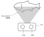
- FIG. 1 is a diagram showing how a fish (aquatic organism) is photographed by a stereo camera.
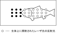
- FIG. 1 is a diagram showing an example of an image showing a fish captured by a stereo camera.
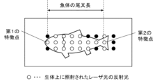
- FIG. 11 is a diagram showing another example of an image showing a fish captured by the stereo camera.
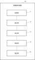
- 1 is a block diagram showing a configuration of an image analysis device according to a first embodiment. 4 is a flowchart showing the operation of the image analyzing device according to the first embodiment.
- FIG. 11 is a block diagram showing a configuration of an image analyzing device according to a second embodiment.
- FIG. 10 is a flowchart showing the operation of an image analyzing device according to a second embodiment.
- FIG. 11 is a block diagram showing a configuration of an image analysis device according to a third embodiment.
- 13 is a flowchart showing the operation of an image analyzing device according to a third embodiment.
- FIG. 2 is a diagram illustrating an example of a hardware configuration of an image analyzing device according to the first to third embodiments.
- FIG. 1 is a diagram showing an example of the configuration of an imaging system 1 including any one of image analysis devices 10, 20, and 30 according to embodiments 1 to 3 described below.
- the reference numeral "10 (20, 30)" means "any one of the image analysis devices 10, 20, and 30.”
- the photography system 1 includes an image analysis device 10 (20, 30) and underwater photography equipment 100.
- the underwater photography device 100 includes a stereo camera 210 and an underwater laser pointer 220.
- the stereo camera 210 includes two cameras (a left camera 210A and a right camera 210B).
- Fig. 2 is a diagram showing how a fish (aquatic organism) is photographed by stereo camera 210.
- a fish moves in the water from right to left within the angle of view of stereo camera 210.
- left camera 210A and right camera 210B each have an angle of view, but Fig. 2 shows only one angle of view for simplicity.
- the image captured by the stereo camera 210 can be used to derive the distance from the stereo camera 210 to each characteristic point of the fish by triangulation.
- the underwater laser pointer 220 emits a laser beam in the visible range.
- the underwater laser pointer 220 has waterproof performance so that it can be used underwater.
- the underwater laser pointer 220 can emit multiple laser beams simultaneously.
- the underwater laser pointer 220 may emit multiple laser beams of different colors.
- the underwater laser pointer 220 may emit multiple laser beams having different irradiation shapes.
- Figures 3 and 4 are each examples of images of a fish captured by the stereo camera 210.
- the reflected light of the multiple laser beams emitted from the underwater laser pointer 220 that are irradiated onto the fish are represented by white dots, and the rest are represented by black dots.
- the entire side of the fish is shown in the center of the image.
- Multiple laser beams emitted from the underwater laser pointer 220 are irradiated onto the entire side of the fish.
- the length from the position of the reflected light corresponding to the snout of the fish (an example of a first characteristic point) to the position of the reflected light corresponding to the center of the fish's tail fin (an example of a second characteristic point) is called the fork length of the fish.
- the fork length is one of the representative indicators of the size of the fish.
- the underwater photography device 100 transmits data of images (Figs. 3 and 4) showing fish captured by the stereo camera 210 to the image analysis device 10 (20, 30) via a wired or wireless network.
- the image analysis device 10 (20, 30) measures the size of the fish (for example, the fork length mentioned above) by analyzing the image data received from the underwater photography device 100.
- the configuration and operation of the image analysis device 10 (20, 30) will be described in detail in the first to third embodiments.
- Fig. 5 is a block diagram showing the configuration of the image analyzing device 10.
- the image analysis device 10 is realized as application software installed on a communication terminal (e.g., a smartphone) carried by a person who grows aquatic organisms.
- a communication terminal e.g., a smartphone
- the image analysis device 10 is realized as a computer program.
- the image analysis device 10 can be realized as hardware that utilizes computer resources.
- the image analysis device 10 includes an acquisition unit 11, a detection unit 12, an extraction unit 13, and a measurement unit 14.
- the acquisition unit 11 acquires images of living aquatic organisms (fish in this case) captured by a stereo camera 210 ( Figure 2).
- the acquisition unit 11 is an example of an acquisition means.
- the acquisition unit 11 receives image data (FIGS. 3 and 4) showing a living organism captured by the stereo camera 210 from the underwater photography equipment 100 via a wired or wireless network.
- the acquisition unit 11 acquires image data uploaded to a server on the network by downloading it. At this time, the acquisition unit 11 may acquire only images showing the entire living organism from among images of an aquatic organism captured by the stereo camera 210.
- the acquisition unit 11 outputs the acquired image data to the detection unit 12.
- the detection unit 12 detects reflected light of multiple laser beams irradiated onto the living body of the aquatic organism from the image acquired by the acquisition unit 11 as multiple characteristic points of the living body.
- the detection unit 12 is an example of a detection means.
- the detection unit 12 receives image data of a living aquatic organism captured by the stereo camera 210 from the acquisition unit 11. The detection unit 12 then detects reflected light of multiple laser beams irradiated onto the organism in the received image. At this time, the detection unit 12 distinguishes between reflected light of multiple laser beams irradiated onto the organism (white dots in FIG. 3 or FIG. 4) and other reflected light of laser beams that were not irradiated onto the organism (black dots in FIG. 3 or FIG. 4).
- the detection unit 12 detects the brightness of the reflected light of the laser light from the received image. Then, based on the brightness of the reflected light of the laser light, the detection unit 12 distinguishes between the reflected light of the laser light irradiated to the living body and other reflected light. Specifically, if the brightness of the reflected light of the laser light exceeds a threshold value, the detection unit 12 determines that the reflected light has been irradiated to the living body, whereas if the brightness of the reflected light of the laser light is equal to or lower than the threshold value, the detection unit 12 determines that the reflected light has not been irradiated to the living body.
- the detection unit 12 distinguishes between reflected light of laser light irradiated to a living body and reflected light of other laser light, based on the distance from the position of the stereo camera 210 to the position where the laser light is reflected. Specifically, the detection unit 12 compares an image captured by the left camera 210A (FIG. 2) of the stereo camera 210 with an image captured by the right camera 210B (FIG. 2) and calculates the distance from the position of the stereo camera 210 to the position where the laser light is reflected by a known method such as triangulation.
- the detection unit 12 determines that the reflected light has been irradiated to a living body, whereas if the measured distance is equal to or closer to the certain value, the detection unit 12 determines that the reflected light has not been irradiated to a living body.
- the detection unit 12 outputs information indicating the positions of the reflected light of the multiple laser beams irradiated onto the living body to the extraction unit 13 as information indicating multiple characteristic points of the living body.
- the information indicating multiple characteristic points of the living body includes information for identifying pixels on the image that correspond to each characteristic point.
- the extraction unit 13 extracts a first feature point corresponding to a first part of the aquatic organism and a second feature point corresponding to a second part of the aquatic organism from among the multiple feature points detected by the detection unit 12.
- the extraction unit 13 is an example of an extraction means.
- the extraction unit 13 receives information indicating a plurality of characteristic points of a living organism from the detection unit 12.
- the extraction unit 13 uses the information indicating the plurality of characteristic points of the living organism to extract, from the plurality of characteristic points of the living organism, a first characteristic point corresponding to a first part of the aquatic organism and a second characteristic point corresponding to a second part of the aquatic organism. Examples of combinations of the first characteristic points and the second characteristic points are shown below.
- the extraction unit 13 extracts a first feature point corresponding to the proboscis of the aquatic organism, and also extracts a second feature point corresponding to the tail fin of the aquatic organism ( Figure 4). In this case, the extraction unit 13 extracts a white dot on the left edge of the image as the first feature point of the organism. The extraction unit 13 also extracts a white dot on the right edge of the image as the second feature point of the organism.
- the extraction unit 13 extracts a first feature point corresponding to the ventral edge of the aquatic organism, and also extracts a second feature point corresponding to the dorsal edge of the aquatic organism. In this case, the extraction unit 13 extracts a white dot at the bottom edge of the image as the first feature point of the organism. The extraction unit 13 also extracts a white dot at the top edge of the image as the second feature point of the organism.
- the extraction unit 13 outputs information indicating the first feature point and the second feature point to the measurement unit 14.
- the information indicating the first feature point and the second feature point includes information for identifying pixels on the image that correspond to each feature point.
- the measuring unit 14 measures the size of the living body based on the distance between the first feature point and the second feature point.
- the measuring unit 14 is an example of a measuring means.
- the measurement unit 14 receives information indicating the first feature point and the second feature point from the extraction unit 13.
- the measurement unit 14 measures the size of the living body based on the distance between the first feature point and the second feature point.
- the measurement unit 14 measures the fork length of the organism based on the distance between the first feature point and the second feature point.
- the measurement unit 14 measures the body height of the organism based on the distance between the first characteristic point and the second characteristic point.
- the measurement unit 14 may transmit information indicating the size of the living body measured in this manner to any external device or storage device (not shown).
- the weight of the aquatic organism may be estimated from the size of the organism measured by the measuring unit 14 (embodiment 2).
- Fig. 6 is a flowchart showing the operation of the image analyzing device 10.
- the acquisition unit 11 acquires images (FIGS. 3 and 4) of a living aquatic organism captured by the stereo camera 210 (S101).
- the acquisition unit 11 outputs data of the acquired images to the detection unit 12.
- the detection unit 12 receives image data of a living aquatic organism captured by the stereo camera 210 from the acquisition unit 11. The detection unit 12 then detects reflected light of multiple laser beams irradiated onto the living organism as multiple characteristic points of the living organism from the image acquired by the acquisition unit 11 (S102).
- the detection unit 12 outputs information indicating the positions of the reflected light of the multiple laser beams irradiated onto the living body to the extraction unit 13 as information indicating multiple characteristic points of the living body.
- the extraction unit 13 receives information indicating a plurality of feature points of the living organism from the detection unit 12.
- the extraction unit 13 extracts a first feature point corresponding to a first part of the aquatic organism and a second feature point corresponding to a second part of the aquatic organism from the plurality of feature points detected by the detection unit 12 (S103).
- the extraction unit 13 outputs information indicating the first feature point and the second feature point to the measurement unit 14.
- the measurement unit 14 receives information indicating the first feature point and the second feature point from the extraction unit 13. The measurement unit 14 then measures the size of the living body based on the distance between the first feature point and the second feature point in the image (S104).
- the measurement unit 14 measures the fork length (one example of the size of the organism) of an aquatic organism based on the distance between the first feature point and the second feature point.
- the acquisition unit 11 acquires an image of an aquatic organism captured by the stereo camera 210.
- the detection unit 12 detects reflected light of a plurality of laser beams irradiated to the organism from the acquired image as a plurality of feature points of the organism.
- the extraction unit 13 extracts a first feature point corresponding to a first part of the aquatic organism and a second feature point corresponding to a second part of the aquatic organism from the detected plurality of feature points.
- the measurement unit 14 measures the size of the organism based on the distance between the first feature point and the second feature point in the image.
- the reflected light of the plurality of laser beams irradiated to the organism is detected as a feature point of the aquatic organism.
- the size of the organism can be accurately measured based on the position of the reflected light of the plurality of laser beams irradiated to the organism.
- FIG. 2 A second embodiment will be described with reference to Figures 7 and 8.
- a configuration will be described in which the size of the living body of an aquatic organism is measured, and then the weight of the living body of the aquatic organism is estimated from the measured size of the living body.
- the same components as those described in the first embodiment are denoted by the same reference numerals, and the description of the components in the first embodiment will be cited, and the description of the components in the second embodiment will be omitted.
- Fig. 7 is a block diagram showing the configuration of the image analyzing device 20.
- the image analysis device 20 includes an acquisition unit 11, a detection unit 12, an extraction unit 13, and a measurement unit 14.
- the image analysis device 20 further includes an estimation unit 25.
- the estimation unit 25 estimates the weight of the aquatic organism from the size of the organism measured by the measurement unit 14.
- the estimation unit 25 is an example of an estimation means.
- the estimation unit 25 receives information indicating the size of the living organism from the measurement unit 14.
- the information indicating the size of the living organism is, for example, the fork length or body height of the living organism of an aquatic organism.
- the estimation unit 25 also acquires statistical data indicating the relationship between the size and weight of the living organism, or a correlation coefficient between the size and weight of the living organism. The estimation unit 25 then uses the information indicating the size of the living organism and the statistical data or the correlation coefficient to estimate the weight of the living organism from the measured size of the living organism.
- the estimation unit 25 may transmit information indicating the weight of the living body estimated in this manner to any external device or storage device (not shown).
- Fig. 8 is a flowchart showing the operation of the image analyzing device 20.
- the acquisition unit 11 acquires images (FIGS. 3 and 4) of a living aquatic organism captured by the stereo camera 210 (S201).
- the acquisition unit 11 outputs data of the acquired images to the detection unit 12.
- the detection unit 12 receives image data of a living aquatic organism captured by the stereo camera 210 from the acquisition unit 11. The detection unit 12 then detects reflected light of multiple laser beams irradiated onto the living organism as multiple characteristic points of the living organism from the image acquired by the acquisition unit 11 (S202).
- the detection unit 12 outputs information indicating the positions of the reflected light of the multiple laser beams irradiated onto the living body to the extraction unit 13 as information indicating multiple characteristic points of the living body.
- the extraction unit 13 receives information indicating a plurality of feature points of the living organism from the detection unit 12.
- the extraction unit 13 extracts a first feature point corresponding to a first part of the aquatic organism and a second feature point corresponding to a second part of the aquatic organism from the plurality of feature points detected by the detection unit 12 (S203).
- the extraction unit 13 outputs information indicating the first feature point and the second feature point to the measurement unit 14.
- the measurement unit 14 receives information indicating the first feature point and the second feature point from the extraction unit 13. The measurement unit 14 then measures the size of the living body based on the distance between the first feature point and the second feature point in the image (S204).
- the measurement unit 14 measures the fork length (one example of the size of the organism) of an aquatic organism based on the distance between the first feature point and the second feature point.
- the measurement unit 14 outputs information indicating the size of the living body to the estimation unit 25.
- the estimation unit 25 receives information indicating the size of the aquatic organism's body from the measurement unit 14.
- the estimation unit 25 also obtains statistical data indicating the relationship between the size and weight of the organism, or a correlation coefficient between the size and weight of the organism.
- the estimation unit 25 uses the information indicating the size of the living body and the statistical data or the correlation coefficient to estimate the weight of the living body from the measured size of the living body (S205).
- the acquisition unit 11 acquires an image of an aquatic organism captured by the stereo camera 210.
- the detection unit 12 detects reflected light of a plurality of laser beams irradiated to the organism from the acquired image as a plurality of feature points of the organism.
- the extraction unit 13 extracts a first feature point corresponding to a first part of the aquatic organism and a second feature point corresponding to a second part of the aquatic organism from the detected plurality of feature points.
- the measurement unit 14 measures the size of the organism based on the distance between the first feature point and the second feature point in the image.
- the reflected light of the plurality of laser beams irradiated to the organism is detected as a feature point of the aquatic organism.
- the size of the organism can be accurately measured based on the position of the reflected light of the plurality of laser beams irradiated to the organism.
- the estimation unit 25 estimates the weight of the living organism from the measured size of the living organism. This makes it possible to measure the approximate weight of an aquatic organism without removing the living organism from the water.
- FIG. 9 A third embodiment will be described with reference to Fig. 9 and Fig. 10.
- a configuration for recognizing the shape of an aquatic organism from the positional relationship between a plurality of feature points detected from the organism will be described.
- the same components as those described in the first or second embodiment are denoted by the same reference numerals, and the description of the components in the first or second embodiment will be cited, and the description of the components in the third embodiment will be omitted.
- Fig. 9 is a block diagram showing the configuration of the image analysis device 30.
- the image analysis device 30 includes an acquisition unit 11, a detection unit 12, an extraction unit 13, and a measurement unit 14.
- the image analysis device 30 further includes a recognition unit 35.
- the recognition unit 35 recognizes the shape of the aquatic organism from the positional relationship between the multiple feature points detected by the detection unit 12.
- the recognition unit 35 is an example of a recognition means.
- the recognition unit 35 receives information indicating multiple characteristic points of the living body from the detection unit 12.
- the multiple characteristic points of the living body correspond to multiple reflected lights of the laser light irradiated to the living body (FIGS. 3 and 4).
- the recognition unit 35 uses information indicating multiple characteristic points of the living body to recognize the shape of the living body of the aquatic organism from the positional relationship between the multiple characteristic points detected by the detection unit 12. For example, the recognition unit 35 recognizes the shape of the living body of the aquatic organism by connecting adjacent characteristic points with lines.
- the recognition unit 35 outputs the recognition result of the shape of the living body.
- the recognition unit 35 outputs image data showing the recognized shape of the living body to a communication device (e.g., a tablet terminal) carried by the grower. Furthermore, the recognition unit 35 may transmit the recognition result of the shape of the living body to any external device or storage device (not shown).
- a communication device e.g., a tablet terminal
- the recognition unit 35 may transmit the recognition result of the shape of the living body to any external device or storage device (not shown).
- Fig. 10 is a flowchart showing the operation of the image analyzing device 30.
- the acquisition unit 11 acquires images (FIGS. 3 and 4) of a living aquatic organism captured by the stereo camera 210 (S301).
- the acquisition unit 11 outputs data of the acquired images to the detection unit 12.
- the detection unit 12 receives image data of a living aquatic organism captured by the stereo camera 210 from the acquisition unit 11. The detection unit 12 then detects reflected light of multiple laser beams irradiated onto the living organism as multiple characteristic points of the living organism from the image acquired by the acquisition unit 11 (S302).
- the detection unit 12 outputs information indicating the positions of the reflected light of the multiple laser beams irradiated onto the living body to the extraction unit 13 and the recognition unit 35 as information indicating multiple characteristic points of the living body.
- the extraction unit 13 receives information indicating a plurality of feature points of the living organism from the detection unit 12.
- the extraction unit 13 extracts a first feature point corresponding to a first part of the aquatic organism and a second feature point corresponding to a second part of the aquatic organism from the plurality of feature points detected by the detection unit 12 (S303).
- the extraction unit 13 extracts a third feature point corresponding to a third part of the living body and a fourth feature point corresponding to a fourth part of the living body from among the multiple feature points detected by the detection unit 12.
- the extraction unit 13 outputs information indicating the first feature point to the fourth feature point to the recognition unit 35 and the measurement unit 14.
- the recognition unit 35 receives information indicating a plurality of characteristic points of the living body from the detection unit 12.
- the recognition unit 35 recognizes the shape of the living body using the information indicating the first characteristic point to the fourth characteristic point (S304).
- the recognition unit 35 recognizes the shape of the living body based on the ratio of a first distance between the first feature point and the second feature point to a second distance between the third feature point and the fourth feature point.
- the recognition unit 35 can recognize a more detailed shape of the living body based on the positions of more feature points.
- the measurement unit 14 receives information indicating the first feature point to the fourth feature point from the extraction unit 13. The measurement unit 14 then measures the size of the living body based on the distance between the first feature point and the second feature point in the image (S305).
- the measurement unit 14 measures the fork length (one example of the size of the organism) of an aquatic organism based on the distance between the first feature point and the second feature point.
- the acquisition unit 11 acquires an image of an aquatic organism captured by the stereo camera 210.
- the detection unit 12 detects reflected light of a plurality of laser beams irradiated to the organism from the acquired image as a plurality of feature points of the organism.
- the extraction unit 13 extracts a first feature point corresponding to a first part of the aquatic organism and a second feature point corresponding to a second part of the aquatic organism from the detected plurality of feature points.
- the measurement unit 14 measures the size of the organism based on the distance between the first feature point and the second feature point in the image.
- the reflected light of the plurality of laser beams irradiated to the organism is detected as a feature point of the aquatic organism.
- the size of the organism can be accurately measured based on the position of the reflected light of the plurality of laser beams irradiated to the organism.
- the recognition unit 35 recognizes the shape of the aquatic organism's body from the positional relationship between the multiple feature points detected by the detection unit 12. This allows the grower to know the approximate shape of the aquatic organism's body, and therefore to determine whether there are any abnormalities in the shape of the organism.
- An imaging system 1 includes an image analyzing device 10 including a stereo camera 210, an underwater laser pointer 220 that emits laser light, an acquisition unit 11 that acquires an image of a living aquatic organism captured by the stereo camera 210, a detection unit 12 that detects reflected light of a plurality of laser beams irradiated onto the organism from the acquired image as a plurality of feature points of the organism, an extraction unit 13 that extracts a first feature point corresponding to a first part of the aquatic organism and a second feature point corresponding to a second part of the aquatic organism from the detected plurality of feature points, and a measurement unit 14 that measures a size of the organism based on a first distance between the first feature point and the second feature point in the image and a second distance from the stereo camera 210 to the aquatic organism.
- the acquisition unit 11 acquires an image of an aquatic organism captured by the stereo camera 210.
- the detection unit 12 detects reflected light of a plurality of laser beams irradiated to the organism from the acquired image as a plurality of feature points of the organism.
- the extraction unit 13 extracts a first feature point corresponding to a first part of the aquatic organism and a second feature point corresponding to a second part of the aquatic organism from the detected plurality of feature points.
- the measurement unit 14 measures the size of the organism based on the distance between the first feature point and the second feature point in the image.
- the reflected light of the plurality of laser beams irradiated to the organism is detected as a feature point of the aquatic organism.
- the size of the organism can be accurately measured based on the position of the reflected light of the plurality of laser beams irradiated to the organism.
- Fig. 11 is a block diagram showing an example of the hardware configuration of the information processing device.
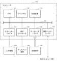
- the computer 110 comprises a CPU (Central Processing Unit) 111, a main memory 112, a storage device 113, an input interface 114, a display controller 115, a data reader/writer 116, and a communication interface 117. These components are connected to each other via a bus 121 so as to be able to communicate data with each other.
- the computer 110 may comprise a GPU (Graphics Processing Unit) or an FPGA (Field-Programmable Gate Array) in addition to or instead of the CPU 111.
- the CPU 111 deploys the program (code) of this embodiment stored in the storage device 113 into the main memory 112 and executes it in a predetermined order to perform various calculations.
- the main memory 112 is typically a volatile storage device such as a DRAM (Dynamic Random Access Memory).
- the program of this embodiment is provided in a state stored in a computer-readable recording medium 120.
- the program of this embodiment may be distributed over the Internet connected via the communication interface 117.
- the storage device 113 include a hard disk drive and a semiconductor storage device such as a flash memory.
- the input interface 114 mediates data transmission between the CPU 111 and input devices 118 such as a keyboard and a mouse.
- the display controller 115 is connected to the display device 119 and controls the display on the display device 119.
- the data reader/writer 116 mediates data transmission between the CPU 111 and the recording medium 120, reads programs from the recording medium 120, and writes the results of processing in the computer 110 to the recording medium 120.
- the communication interface 117 mediates data transmission between the CPU 111 and other computers.
- the recording medium 120 include general-purpose semiconductor storage devices such as CF (Compact Flash (registered trademark)) and SD (Secure Digital), magnetic recording media such as a flexible disk, or optical recording media such as a CD-ROM (Compact Disk Read Only Memory).
- CF Compact Flash
- SD Secure Digital
- magnetic recording media such as a flexible disk
- optical recording media such as a CD-ROM (Compact Disk Read Only Memory).
- An acquisition means for acquiring images of a living aquatic organism using a stereo camera; a detection means for detecting reflected light of a plurality of laser beams irradiated onto the living body from the acquired image as a plurality of feature points of the living body; an extraction means for extracting a first feature point corresponding to a first portion of the aquatic organism and a second feature point corresponding to a second portion of the aquatic organism from the detected plurality of feature points; and a measuring means for measuring a size of the living body based on a distance between the first feature point and the second feature point.
- Appendix 3 The image analysis device described in Appendix 1, characterized in that the detection means distinguishes between reflected light of the multiple laser beams irradiated to the living body and reflected light of other laser beams based on a brightness of the reflected light of the laser beam.
- the detection means distinguishes between reflected light of the laser light irradiated to the living body and other reflected light based on a distance from a position of the stereo camera to a position where the laser light is reflected.
- a stereo camera and a laser pointer that emits a plurality of laser beams An acquisition means for acquiring images of a living aquatic organism using a stereo camera; a detection means for detecting reflected light of a plurality of laser beams irradiated onto the living body from the acquired image as a plurality of feature points of the living body; an extraction means for extracting a first feature point corresponding to a first portion of the aquatic organism and a second feature point corresponding to a second portion of the aquatic organism from the detected plurality of feature points; an image analyzing device including: a measuring means for measuring a size of the living organism based on a first distance between the first feature point and the second feature point in the image and a second distance from the stereo camera to the aquatic organism; A photography system equipped with
- Images of live aquatic organisms are captured using a stereo camera, Detecting reflected light of a plurality of laser beams irradiated onto the living body from the acquired image as a plurality of feature points of the living body; extracting a first feature point corresponding to a first portion of the aquatic organism and a second feature point corresponding to a second portion of the aquatic organism from the detected plurality of feature points; measuring a size of the living body based on a distance between the first feature point and the second feature point in the image.
- (Appendix 16) Obtaining images of live aquatic organisms using a stereo camera; Detecting reflected light of a plurality of laser beams irradiated onto the living body from the acquired image as a plurality of feature points of the living body; extracting a first feature point corresponding to a first part of the aquatic organism and a second feature point corresponding to a second part of the aquatic organism from the detected plurality of feature points; and measuring a size of the living body based on a distance between the first feature point and the second feature point in the image.
- the present invention can be used, for example, to manage the growth of aquatic organisms by using images of the organisms.
Landscapes
- Physics & Mathematics (AREA)
- Engineering & Computer Science (AREA)
- General Physics & Mathematics (AREA)
- Computer Vision & Pattern Recognition (AREA)
- Theoretical Computer Science (AREA)
- Geometry (AREA)
- Length Measuring Devices By Optical Means (AREA)
Abstract
画像中の生体の姿が不鮮明になっている場合であっても、生体の大きさを精度よく測定できるようにする。取得部(11)は、ステレオカメラによって水生生物の生体を撮影した画像を取得し、検出部(12)は、取得した画像から、生体に照射された複数のレーザ光の反射光を、生体の複数の特徴点として検出し、抽出部(13)は、検出した複数の特徴点のうち、前記水生生物の第1の部位と対応する第1の特徴点と、水生生物の第2の部位と対応する第2の特徴点とを抽出し、測定部(14)は、画像における第1の特徴点と第2の特徴点との間の距離に基づき、生体の大きさを測定する。
Description
本発明は、画像解析装置、撮影システム、画像解析方法、および記録媒体に関し、特に、画像に映る生体の大きさを測定するための画像解析装置、撮影システム、画像解析方法、および記録媒体に関する。
水槽や生け簀で生育されている魚などの水生生物の生体の大きさを測定するための、関連する技術が存在する。
特許文献1に記載の関連する技術では、ステレオカメラによって、魚(水生生物の一例)の生体を撮影して、生体の全体が映る画像から、吻や尾びれなどの特定の部位と対応する複数の特徴点を検出する。そして、関連する技術では、ステレオカメラを構成する2台のカメラの視差を利用して、三角測量法等の一般的な手法により、検出した複数の特徴点間の距離を計算する。これにより、水生生物の生体を水中から取り出すことなく、生体の大きさを測定することができる。
一例では、魚の生体の尾叉長が測定される。また他の例では、測定された生体の大きさから、生体の重量が推測される。
ステレオカメラによる距離計算では、2台のカメラ画像に映り込んだ物体の特徴点の位置を正確に指定できない場合、測定精度が低下する。水が濁っている環境や、あるいは暗い環境などでは、画像中の水生生物の姿(輪郭)が不鮮明になるので、関連する技術では、2台のカメラ画像の生体の特徴点の指定位置がズレてしまう場合がある。そのような場合、関連する技術では、生体の大きさを精度よく測定することができない。
本発明は、上記の課題に鑑みてなされたものであり、その目的は、画像中の生体の姿が不鮮明になっている場合であっても、生体の大きさを精度よく測定できるようにすることにある。
上記の課題を解決するために、本発明の一態様に係る画像解析装置は、ステレオカメラによって水生生物の生体を撮影した画像を取得する取得手段と、取得した前記画像から、前記生体に照射された複数のレーザ光の反射光を、前記生体の複数の特徴点として検出する検出手段と、検出した前記複数の特徴点のうち、前記水生生物の第1の部位と対応する第1の特徴点と、前記水生生物の第2の部位と対応する第2の特徴点とを抽出する抽出手段と、前記第1の特徴点と前記第2の特徴点との間の距離に基づき、前記生体の大きさを測定する測定手段と、を備えている。
本発明の一態様に係る撮影システムは、ステレオカメラと、レーザ光を出射するレーザポインタと、ステレオカメラによって水生生物の生体を撮影した画像を取得する取得手段と、取得した前記画像から、前記生体に照射された複数のレーザ光の反射光を、前記生体の複数の特徴点として検出する検出手段と、検出した前記複数の特徴点のうち、前記水生生物の第1の部位と対応する第1の特徴点と、前記水生生物の第2の部位と対応する第2の特徴点とを抽出する抽出手段と、前記画像における前記第1の特徴点と前記第2の特徴点との間の第1の距離と、前記ステレオカメラから前記水生生物までの第2の距離とに基づき、前記生体の大きさを測定する測定手段と、を備えた画像解析装置と、を備えている。
本発明の一態様に係る画像解析方法では、コンピュータが、ステレオカメラによって水生生物の生体を撮影した画像を取得し、取得した前記画像から、前記生体に照射された複数のレーザ光の反射光を、前記生体の複数の特徴点として検出し、検出した前記複数の特徴点のうち、前記水生生物の第1の部位と対応する第1の特徴点と、前記水生生物の第2の部位と対応する第2の特徴点とを抽出し、前記画像における前記第1の特徴点と前記第2の特徴点との間の距離に基づき、前記生体の大きさを測定する。
本発明の一態様に係る記録媒体は、ステレオカメラによって水生生物の生体を撮影した画像を取得することと、取得した前記画像から、前記生体に照射された複数のレーザ光の反射光を、前記生体の複数の特徴点として検出することと、検出した前記複数の特徴点のうち、前記水生生物の第1の部位と対応する第1の特徴点と、前記水生生物の第2の部位と対応する第2の特徴点とを抽出することと、前記画像における前記第1の特徴点と前記第2の特徴点との間の距離に基づき、前記生体の大きさを測定することとをコンピュータに実行させるためのプログラムを格納している。
本発明の一態様によれば、画像中の生体の姿が不鮮明になっている場合であっても、生体の大きさを精度よく測定できる。
図面を参照して、本発明の実施形態について、以下で説明する。
(撮影システム1)
図1は、後述する実施形態1~3に係る画像解析装置10,20,30のいずれかを備えた撮影システム1の構成の一例を示す図である。図1において、符号「10(20,30)」は、「画像解析装置10,20,30のいずれか」を意味する。
図1は、後述する実施形態1~3に係る画像解析装置10,20,30のいずれかを備えた撮影システム1の構成の一例を示す図である。図1において、符号「10(20,30)」は、「画像解析装置10,20,30のいずれか」を意味する。
図1に示すように、撮影システム1は、画像解析装置10(20,30)、および水中撮影機器100を備えている。
図1に示すように、水中撮影機器100は、ステレオカメラ210と水中レーザポインタ220を備えている。ステレオカメラ210は、2台のカメラ(左カメラ210Aと右カメラ210B)を備えている。
(ステレオカメラ210)
図2は、ステレオカメラ210によって魚(水生生物)を撮影する様子を示す図である。図2では、ステレオカメラ210の画角内を、魚が右から左へ向かって、水中を移動している。実際には、左カメラ210Aと右カメラ210Bのそれぞれに画角が存在するが、図2では、簡単のため、1つの画角のみを示している。
図2は、ステレオカメラ210によって魚(水生生物)を撮影する様子を示す図である。図2では、ステレオカメラ210の画角内を、魚が右から左へ向かって、水中を移動している。実際には、左カメラ210Aと右カメラ210Bのそれぞれに画角が存在するが、図2では、簡単のため、1つの画角のみを示している。
ステレオカメラ210の左カメラ210Aの画角と右カメラ210Bの画角との間には、視差があるため、ステレオカメラ210によって撮影された画像を使って、三角測量法により、ステレオカメラ210から魚体の各特徴点までの距離を導出することができる。
(水中レーザポインタ220)
水中レーザポインタ220は、可視域のレーザ光を出射する。水中レーザポインタ220は、水中でも使用できるように、防水性能を有している。水中レーザポインタ220は、複数本のレーザ光を、同時に出射することが可能である。
水中レーザポインタ220は、可視域のレーザ光を出射する。水中レーザポインタ220は、水中でも使用できるように、防水性能を有している。水中レーザポインタ220は、複数本のレーザ光を、同時に出射することが可能である。
例えば、水中レーザポインタ220は、互いに異なる色の複数本のレーザ光を出射してもよい。あるいは、水中レーザポインタ220は、互いに異なる照射形状を有する複数本のレーザ光を出射してもよい。
図3および図4は、それぞれ、ステレオカメラ210によって撮影された魚が映っている画像の一例である。図3あるいは図4では、画像中、水中レーザポインタ220から出射された複数本のレーザ光のうち、魚体に照射された複数のレーザ光の反射光を白点で表し、それ以外を黒点で表している。
図3では、画像の中央よりも右寄りに、魚体の側面の全体が写っている。魚体の一部分(側面の頭部側)には、水中レーザポインタ220から出射された複数本のレーザ光の一部が照射されている。
図4では、画像の中央に、魚体の側面の全体が写っている。魚体の側面の全体に、水中レーザポインタ220から出射された複数本のレーザ光が照射されている。魚体の吻と対応する反射光の位置(第1の特徴点の一例)から、魚体の尾びれの中央と対応する反射光の位置(第2の特徴点の一例)までの長さが、魚体の尾叉長と呼ばれる。尾叉長は、魚体の代表的な大きさの指標の一つである。
水中撮影機器100は、有線または無線のネットワークを介して、画像解析装置10(20,30)へ、ステレオカメラ210によって撮影された魚が映っている画像(図3、図4)のデータを送信する。
画像解析装置10(20,30)は、水中撮影機器100から受信した画像のデータを解析することによって、魚体の大きさ(例えば、上述した尾叉長)を測定する。画像解析装置10(20,30)の構成および動作については、実施形態1~3において詳細に説明する。
〔実施形態1〕
図5から図6を参照して、実施形態1について、説明する。
図5から図6を参照して、実施形態1について、説明する。
(画像解析装置10の構成)
図5を参照して、本実施形態1に係る画像解析装置10の構成を説明する。図5は、画像解析装置10の構成を示すブロック図である。
図5を参照して、本実施形態1に係る画像解析装置10の構成を説明する。図5は、画像解析装置10の構成を示すブロック図である。
画像解析装置10は、一例では、水生生物の生育者が所持する通信端末(例えば、スマートフォン)にインストールされたアプリケーションソフトウェアとして実現される。他の一例では、画像解析装置10は、コンピュータプログラムとして実現される。あるいは、画像解析装置10は、コンピュータ資源を利用するハードウェアとしても実現され得る。
図5に示すように、画像解析装置10は、取得部11、検出部12、抽出部13、および測定部14を備えている。
取得部11は、ステレオカメラ210(図2)によって水生生物(ここでは魚)の生体を撮影した画像を取得する。取得部11は、取得手段の一例である。
例えば、取得部11は、水中撮影機器100から、有線または無線のネットワークを介して、ステレオカメラ210によって撮影された生体が映っている画像(図3、図4)のデータを受信する。他の一例では、取得部11は、ネットワーク上のサーバにアップロードされた画像のデータを、ダウンロードすることによって取得する。このとき、取得部11は、水生生物をステレオカメラ210によって撮影した画像のうち、生体の全体が映る画像のみを取得してもよい。
取得部11は、取得した画像のデータを、検出部12へ出力する。
検出部12は、取得部11が取得した画像から、水生生物の生体に照射された複数のレーザ光の反射光を、生体の複数の特徴点として検出する。検出部12は、検出手段の一例である。
例えば、検出部12は、取得部11から、水生生物の生体をステレオカメラ210によって撮影した画像のデータを受信する。そして、検出部12は、受信した画像において、生体に照射された複数のレーザ光の反射光を検出する。このとき、検出部12は、生体に照射された複数のレーザ光の反射光(図3あるいは図4の白点)と、それ以外すなわち生体に照射されなかったレーザ光の反射光(図3あるいは図4の黒点)とを区別する。
一例では、検出部12は、受信した画像から、レーザ光の反射光の輝度を検知する。そして、検出部12は、レーザ光の反射光の輝度に基づいて、生体に照射されたレーザ光の反射光と、それ以外の反射光とを区別する。具体的には、レーザ光の反射光の輝度が閾値を超えていれば、検出部12は、当該反射光は生体に照射されたとみなす一方、レーザ光の反射光の輝度が閾値以下であれば、検出部12は、当該反射光は生体に照射されなかったとみなす。
他の一例では、検出部12は、ステレオカメラ210の位置から、レーザ光が反射された位置までの距離に基づいて、生体に照射されたレーザ光の反射光と、それ以外のレーザ光の反射光とを区別する。具体的には、検出部12は、ステレオカメラ210の左カメラ210A(図2)が撮影した画像と、右カメラ210B(図2)が撮影した画像とを比較して、三角測量法などの既知の方法により、ステレオカメラ210の位置から、レーザ光が反射された位置までの距離を計算する。そして、測定した距離が一定値よりも遠ければ、検出部12は、当該反射光は生体に照射されたとみなす一方、測定した距離が一定値と同じかそれよりも近ければ、検出部12は、当該反射光は生体に照射されなかったとみなす。
検出部12は、生体に照射された複数のレーザ光の反射光の位置を示す情報を、生体の複数の特徴点を示す情報として、抽出部13へ出力する。生体の複数の特徴点を示す情報は、画像上において、各特徴点と対応する画素を特定するための情報を含む。
抽出部13は、検出部12が検出した複数の特徴点のうち、水生生物の第1の部位と対応する第1の特徴点と、水生生物の第2の部位と対応する第2の特徴点とを抽出する。抽出部13は、抽出手段の一例である。
例えば、抽出部13は、検出部12から、生体の複数の特徴点を示す情報を受信する。抽出部13は、生体の複数の特徴点を示す情報を用いて、生体の複数の特徴点のうち、水生生物の第1の部位と対応する第1の特徴点と、水生生物の第2の部位と対応する第2の特徴点とを抽出する。第1の特徴点と、第2の特徴点の組み合わせを、以下で例示する。
一例では、抽出部13は、水生生物の吻と対応する第1の特徴点を抽出し、また水生生物の尾びれと対応する第2の特徴点を抽出する(図4)。この場合、抽出部13は、画像における左端の白点を、生体の第1の特徴点として抽出する。また、抽出部13は、画像における右端の白点を、生体の第2の特徴点として抽出する。
他の一例では、抽出部13は、水生生物の腹縁と対応する第1の特徴点を抽出し、また水生生物の背縁と対応する第2の特徴点を抽出する。この場合、抽出部13は、画像における下端の白点を、生体の第1の特徴点として抽出する。また、抽出部13は、画像における上端の白点を、生体の第2の特徴点として抽出する。
抽出部13は、第1の特徴点および第2の特徴点を示す情報を、測定部14へ出力する。第1の特徴点および第2の特徴点を示す情報は、画像上において、各特徴点と対応する画素を特定するための情報を含む。
測定部14は、第1の特徴点と第2の特徴点との間の距離に基づき、生体の大きさを測定する。測定部14は、測定手段の一例である。
例えば、測定部14は、抽出部13から、第1の特徴点および第2の特徴点を示す情報を受信する。測定部14は、第1の特徴点と第2の特徴点との間の距離に基づき、生体の大きさを測定する。
一例では、第1の特徴点が水生生物の吻と対応し、また第2の特徴点が水生生物の尾びれと対応する場合、測定部14は、第1の特徴点と第2の特徴点との間の距離に基づき、生体の尾叉長を測定する。
他の一例では、第1の特徴点が水生生物の腹縁と対応し、また第2の特徴点が水生生物の背縁と対応する場合、測定部14は、第1の特徴点と第2の特徴点との間の距離に基づき、生体の体高を測定する。
測定部14は、このようにして測定した生体の大きさを示す情報を、任意の外部機器あるいは記憶装置(図示せず)へ送信してもよい。
あるいは、測定部14が測定した生体の大きさから、水生生物の生体の重量が推定されてもよい(実施形態2)。
(画像解析装置10の動作)
図6を参照して、本実施形態1に係る画像解析装置10の動作を説明する。図6は、画像解析装置10の動作を示すフローチャートである。
図6を参照して、本実施形態1に係る画像解析装置10の動作を説明する。図6は、画像解析装置10の動作を示すフローチャートである。
図6に示すように、取得部11は、ステレオカメラ210によって水生生物の生体を撮影した画像(図3、図4)を取得する(S101)。取得部11は、取得した画像のデータを、検出部12へ出力する。
検出部12は、取得部11から、ステレオカメラ210によって水生生物の生体を撮影した画像のデータを受信する。そして、検出部12は、取得部11が取得した画像から、生体に照射された複数のレーザ光の反射光を、生体の複数の特徴点として検出する(S102)。
検出部12は、生体に照射された複数のレーザ光の反射光の位置を示す情報を、生体の複数の特徴点を示す情報として、抽出部13へ出力する。
抽出部13は、検出部12から、生体の複数の特徴点を示す情報を受信する。抽出部13は、検出部12が検出した複数の特徴点のうち、水生生物の第1の部位と対応する第1の特徴点と、水生生物の第2の部位と対応する第2の特徴点とを抽出する(S103)。
抽出部13は、第1の特徴点および第2の特徴点を示す情報を、測定部14へ出力する。
測定部14は、抽出部13から、第1の特徴点および第2の特徴点を示す情報を受信する。そして、測定部14は、画像における第1の特徴点と第2の特徴点との間の距離に基づき、生体の大きさを測定する(S104)。
例えば、測定部14は、第1の特徴点と第2の特徴点との間の距離に基づき、水生生物の生体の尾叉長(生体の大きさの一例である)を測定する。
以上で、本実施形態1に係る画像解析装置10の動作は終了する。
(本実施形態の効果)
本実施形態の構成によれば、取得部11は、ステレオカメラ210によって水生生物の生体を撮影した画像を取得する。検出部12は、取得した画像から、生体に照射された複数のレーザ光の反射光を、生体の複数の特徴点として検出する。抽出部13は、検出した複数の特徴点のうち、水生生物の第1の部位と対応する第1の特徴点と、水生生物の第2の部位と対応する第2の特徴点とを抽出する。測定部14は、画像における第1の特徴点と第2の特徴点との間の距離に基づき、生体の大きさを測定する。以上のように、生体に照射された複数のレーザ光の反射光が、水生生物の生体の特徴点として検出される。これにより、画像中の生体の姿が不鮮明になっている場合であっても、生体に照射された複数のレーザ光の反射光の位置に基づいて、生体の大きさを精度よく測定できる。
本実施形態の構成によれば、取得部11は、ステレオカメラ210によって水生生物の生体を撮影した画像を取得する。検出部12は、取得した画像から、生体に照射された複数のレーザ光の反射光を、生体の複数の特徴点として検出する。抽出部13は、検出した複数の特徴点のうち、水生生物の第1の部位と対応する第1の特徴点と、水生生物の第2の部位と対応する第2の特徴点とを抽出する。測定部14は、画像における第1の特徴点と第2の特徴点との間の距離に基づき、生体の大きさを測定する。以上のように、生体に照射された複数のレーザ光の反射光が、水生生物の生体の特徴点として検出される。これにより、画像中の生体の姿が不鮮明になっている場合であっても、生体に照射された複数のレーザ光の反射光の位置に基づいて、生体の大きさを精度よく測定できる。
〔実施形態2〕
図7から図8を参照して、実施形態2について、説明する。本実施形態2では、水生生物の生体の大きさを測定した後、測定した生体の大きさから、水生生物の生体の重量を推定する構成を説明する。なお、本実施形態2では、前記実施形態1で説明した構成要素と同じ構成要素に対して、同じ符号を付して、その構成要素に関する前記実施形態1での説明を引用するとともに、その構成要素に関する本実施形態2での説明を省略する。
図7から図8を参照して、実施形態2について、説明する。本実施形態2では、水生生物の生体の大きさを測定した後、測定した生体の大きさから、水生生物の生体の重量を推定する構成を説明する。なお、本実施形態2では、前記実施形態1で説明した構成要素と同じ構成要素に対して、同じ符号を付して、その構成要素に関する前記実施形態1での説明を引用するとともに、その構成要素に関する本実施形態2での説明を省略する。
(画像解析装置20の構成)
図7を参照して、本実施形態2に係る画像解析装置20の構成を説明する。図7は、画像解析装置20の構成を示すブロック図である。
図7を参照して、本実施形態2に係る画像解析装置20の構成を説明する。図7は、画像解析装置20の構成を示すブロック図である。
図7に示すように、画像解析装置20は、取得部11、検出部12、抽出部13、および測定部14を備えている。画像解析装置20は、推定部25をさらに備えている。
推定部25は、測定部14が測定した生体の大きさから、水生生物の生体の重量を推定する。推定部25は、推定手段の一例である。
例えば、推定部25は、測定部14から、生体の大きさを示す情報を受信する。生体の大きさを示す情報は、例えば、水生生物の生体の尾叉長や体高である。
また、推定部25は、生体の大きさと生体の重量との関係を示す統計データ、あるいは、生体の大きさと生体の重量との間の相関係数を取得する。そして、推定部25は、生体の大きさを示す情報と、統計データあるいは相関係数とを使い、測定された生体の大きさから、生体の重量を推定する。
推定部25は、このようにして推定した生体の重量を示す情報を、任意の外部機器あるいは記憶装置(図示せず)へ送信してもよい。
(画像解析装置20の動作)
図8を参照して、本実施形態2に係る画像解析装置20の動作を説明する。図8は、画像解析装置20の動作を示すフローチャートである。
図8を参照して、本実施形態2に係る画像解析装置20の動作を説明する。図8は、画像解析装置20の動作を示すフローチャートである。
図8に示すように、取得部11は、ステレオカメラ210によって水生生物の生体を撮影した画像(図3、図4)を取得する(S201)。取得部11は、取得した画像のデータを、検出部12へ出力する。
検出部12は、取得部11から、ステレオカメラ210によって水生生物の生体を撮影した画像のデータを受信する。そして、検出部12は、取得部11が取得した画像から、生体に照射された複数のレーザ光の反射光を、生体の複数の特徴点として検出する(S202)。
検出部12は、生体に照射された複数のレーザ光の反射光の位置を示す情報を、生体の複数の特徴点を示す情報として、抽出部13へ出力する。
抽出部13は、検出部12から、生体の複数の特徴点を示す情報を受信する。抽出部13は、検出部12が検出した複数の特徴点のうち、水生生物の第1の部位と対応する第1の特徴点と、水生生物の第2の部位と対応する第2の特徴点とを抽出する(S203)。
抽出部13は、第1の特徴点および第2の特徴点を示す情報を、測定部14へ出力する。
測定部14は、抽出部13から、第1の特徴点および第2の特徴点を示す情報を受信する。そして、測定部14は、画像における第1の特徴点と第2の特徴点との間の距離に基づき、生体の大きさを測定する(S204)。
例えば、測定部14は、第1の特徴点と第2の特徴点との間の距離に基づき、水生生物の生体の尾叉長(生体の大きさの一例である)を測定する。
測定部14は、生体の大きさを示す情報を、推定部25へ出力する。
推定部25は、測定部14から、水生生物の生体の大きさを示す情報を受信する。また、推定部25は、生体の大きさと生体の重量との関係を示す統計データ、あるいは、生体の大きさと生体の重量との間の相関係数を取得する。
そして、推定部25は、生体の大きさを示す情報と、統計データあるいは相関係数とを使い、測定された生体の大きさから、生体の重量を推定する(S205)。
以上で、本実施形態2に係る画像解析装置20の動作は終了する。
(本実施形態の効果)
本実施形態の構成によれば、取得部11は、ステレオカメラ210によって水生生物の生体を撮影した画像を取得する。検出部12は、取得した画像から、生体に照射された複数のレーザ光の反射光を、生体の複数の特徴点として検出する。抽出部13は、検出した複数の特徴点のうち、水生生物の第1の部位と対応する第1の特徴点と、水生生物の第2の部位と対応する第2の特徴点とを抽出する。測定部14は、画像における第1の特徴点と第2の特徴点との間の距離に基づき、生体の大きさを測定する。以上のように、生体に照射された複数のレーザ光の反射光が、水生生物の生体の特徴点として検出される。これにより、画像中の生体の姿が不鮮明になっている場合であっても、生体に照射された複数のレーザ光の反射光の位置に基づいて、生体の大きさを精度よく測定できる。
本実施形態の構成によれば、取得部11は、ステレオカメラ210によって水生生物の生体を撮影した画像を取得する。検出部12は、取得した画像から、生体に照射された複数のレーザ光の反射光を、生体の複数の特徴点として検出する。抽出部13は、検出した複数の特徴点のうち、水生生物の第1の部位と対応する第1の特徴点と、水生生物の第2の部位と対応する第2の特徴点とを抽出する。測定部14は、画像における第1の特徴点と第2の特徴点との間の距離に基づき、生体の大きさを測定する。以上のように、生体に照射された複数のレーザ光の反射光が、水生生物の生体の特徴点として検出される。これにより、画像中の生体の姿が不鮮明になっている場合であっても、生体に照射された複数のレーザ光の反射光の位置に基づいて、生体の大きさを精度よく測定できる。
さらに、本実施形態の構成によれば、推定部25は、測定された生体の大きさから、生体の重量を推定する。これにより、水生生物の生体を水中から取り出すことなく、生体のおおよその重量を測定することができる。
〔実施形態3〕
図9から図10を参照して、実施形態3について、説明する。本実施形態3では、生体から検出した複数の特徴点の間の位置関係から、水生生物の生体の形状を認識する構成を説明する。なお、本実施形態3では、前記実施形態1または前記実施形態2で説明した構成要素と同じ構成要素に対して、同じ符号を付して、その構成要素に関する前記実施形態1または前記実施形態2での説明を引用するとともに、その構成要素に関する本実施形態3での説明を省略する。
図9から図10を参照して、実施形態3について、説明する。本実施形態3では、生体から検出した複数の特徴点の間の位置関係から、水生生物の生体の形状を認識する構成を説明する。なお、本実施形態3では、前記実施形態1または前記実施形態2で説明した構成要素と同じ構成要素に対して、同じ符号を付して、その構成要素に関する前記実施形態1または前記実施形態2での説明を引用するとともに、その構成要素に関する本実施形態3での説明を省略する。
(画像解析装置30の構成)
図9を参照して、本実施形態3に係る画像解析装置30の構成を説明する。図9は、画像解析装置30の構成を示すブロック図である。
図9を参照して、本実施形態3に係る画像解析装置30の構成を説明する。図9は、画像解析装置30の構成を示すブロック図である。
図9に示すように、画像解析装置30は、取得部11、検出部12、抽出部13、および測定部14を備えている。画像解析装置30は、認識部35をさらに備えている。
認識部35は、検出部12が検出した複数の特徴点の間の位置関係から、水生生物の生体の形状を認識する。認識部35は、認識手段の一例である。
例えば、認識部35は、検出部12から、生体の複数の特徴点を示す情報を受信する。生体の複数の特徴点は、生体に照射された複数のレーザ光の反射光(図3、図4)と対応する。
認識部35は、生体の複数の特徴点を示す情報を用いて、検出部12が検出した複数の特徴点の間の位置関係から、水生生物の生体の形状を認識する。例えば、認識部35は、隣接する特徴点同士を線で結ぶことにより、水生生物の生体の形状を認識する。
その後、認識部35は、生体の形状の認識結果を出力する。
例えば、認識部35は、生育者が所持する通信機器(例えば、タブレット端末)に、認識した生体の形状を示す画像データを出力する。さらに、認識部35は、生体の形状の認識結果を、任意の外部機器あるいは記憶装置(図示せず)へ送信してもよい。
(画像解析装置30の動作)
図10を参照して、本実施形態3に係る画像解析装置30の動作を説明する。図10は、画像解析装置30の動作を示すフローチャートである。
図10を参照して、本実施形態3に係る画像解析装置30の動作を説明する。図10は、画像解析装置30の動作を示すフローチャートである。
図10に示すように、取得部11は、ステレオカメラ210によって水生生物の生体を撮影した画像(図3、図4)を取得する(S301)。取得部11は、取得した画像のデータを、検出部12へ出力する。
検出部12は、取得部11から、ステレオカメラ210によって水生生物の生体を撮影した画像のデータを受信する。そして、検出部12は、取得部11が取得した画像から、生体に照射された複数のレーザ光の反射光を、生体の複数の特徴点として検出する(S302)。
検出部12は、生体に照射された複数のレーザ光の反射光の位置を示す情報を、生体の複数の特徴点を示す情報として、抽出部13および認識部35へ出力する。
抽出部13は、検出部12から、生体の複数の特徴点を示す情報を受信する。抽出部13は、検出部12が検出した複数の特徴点のうち、水生生物の第1の部位と対応する第1の特徴点と、水生生物の第2の部位と対応する第2の特徴点とを抽出する(S303)。
さらに、抽出部13は、検出部12が検出した複数の特徴点のうち、生体の第3の部位と対応する第3の特徴点と、生体の第4の部位と対応する第4の特徴点とを抽出する。
抽出部13は、第1の特徴点から第4の特徴点を示す情報を、認識部35および測定部14へ出力する。
認識部35は、検出部12から、生体の複数の特徴点を示す情報を受信する。認識部35は、第1の特徴点から第4の特徴点を示す情報を用いて、生体の形状を認識する(S304)。
例えば、認識部35は、第1の特徴点と第2の特徴点との間の第1の距離と、第3の特徴点と第4の特徴点との間の第2の距離との比率に基づき、生体の形状を認識する。あるいは、認識部35は、より多くの特徴点の位置に基づき、生体のより詳細な形状を認識することもできる。
測定部14は、抽出部13から、第1の特徴点から第4の特徴点を示す情報を受信する。そして、測定部14は、画像における第1の特徴点と第2の特徴点との間の距離に基づき、生体の大きさを測定する(S305)。
例えば、測定部14は、第1の特徴点と第2の特徴点との間の距離に基づき、水生生物の生体の尾叉長(生体の大きさの一例である)を測定する。
以上で、本実施形態3に係る画像解析装置30の動作は終了する。
(本実施形態の効果)
本実施形態の構成によれば、取得部11は、ステレオカメラ210によって水生生物の生体を撮影した画像を取得する。検出部12は、取得した画像から、生体に照射された複数のレーザ光の反射光を、生体の複数の特徴点として検出する。抽出部13は、検出した複数の特徴点のうち、水生生物の第1の部位と対応する第1の特徴点と、水生生物の第2の部位と対応する第2の特徴点とを抽出する。測定部14は、画像における第1の特徴点と第2の特徴点との間の距離に基づき、生体の大きさを測定する。以上のように、生体に照射された複数のレーザ光の反射光が、水生生物の生体の特徴点として検出される。これにより、画像中の生体の姿が不鮮明になっている場合であっても、生体に照射された複数のレーザ光の反射光の位置に基づいて、生体の大きさを精度よく測定できる。
本実施形態の構成によれば、取得部11は、ステレオカメラ210によって水生生物の生体を撮影した画像を取得する。検出部12は、取得した画像から、生体に照射された複数のレーザ光の反射光を、生体の複数の特徴点として検出する。抽出部13は、検出した複数の特徴点のうち、水生生物の第1の部位と対応する第1の特徴点と、水生生物の第2の部位と対応する第2の特徴点とを抽出する。測定部14は、画像における第1の特徴点と第2の特徴点との間の距離に基づき、生体の大きさを測定する。以上のように、生体に照射された複数のレーザ光の反射光が、水生生物の生体の特徴点として検出される。これにより、画像中の生体の姿が不鮮明になっている場合であっても、生体に照射された複数のレーザ光の反射光の位置に基づいて、生体の大きさを精度よく測定できる。
さらに、本実施形態の構成によれば、認識部35は、検出部12が検出した複数の特徴点の間の位置関係から、水生生物の生体の形状を認識する。これにより、生育者は、水生生物の生体のおおよその形状を知ることができるので、生体の形状に異常がないかどうかを判断することができる。
〔その他の実施形態〕
他の一実施形態に係る撮影システム1は、ステレオカメラ210と、レーザ光を出射する水中レーザポインタ220と、ステレオカメラ210によって水生生物の生体を撮影した画像を取得する取得部11と、取得した画像から、生体に照射された複数のレーザ光の反射光を、生体の複数の特徴点として検出する検出部12と、検出した複数の特徴点のうち、水生生物の第1の部位と対応する第1の特徴点と、水生生物の第2の部位と対応する第2の特徴点とを抽出する抽出部13と、画像における第1の特徴点と第2の特徴点との間の第1の距離と、ステレオカメラ210から水生生物までの第2の距離とに基づき、生体の大きさを測定する測定部14と、を備えた画像解析装置10と、を備えている。
他の一実施形態に係る撮影システム1は、ステレオカメラ210と、レーザ光を出射する水中レーザポインタ220と、ステレオカメラ210によって水生生物の生体を撮影した画像を取得する取得部11と、取得した画像から、生体に照射された複数のレーザ光の反射光を、生体の複数の特徴点として検出する検出部12と、検出した複数の特徴点のうち、水生生物の第1の部位と対応する第1の特徴点と、水生生物の第2の部位と対応する第2の特徴点とを抽出する抽出部13と、画像における第1の特徴点と第2の特徴点との間の第1の距離と、ステレオカメラ210から水生生物までの第2の距離とに基づき、生体の大きさを測定する測定部14と、を備えた画像解析装置10と、を備えている。
(本実施形態の効果)
本実施形態の構成によれば、取得部11は、ステレオカメラ210によって水生生物の生体を撮影した画像を取得する。検出部12は、取得した画像から、生体に照射された複数のレーザ光の反射光を、生体の複数の特徴点として検出する。抽出部13は、検出した複数の特徴点のうち、水生生物の第1の部位と対応する第1の特徴点と、水生生物の第2の部位と対応する第2の特徴点とを抽出する。測定部14は、画像における第1の特徴点と第2の特徴点との間の距離に基づき、生体の大きさを測定する。以上のように、生体に照射された複数のレーザ光の反射光が、水生生物の生体の特徴点として検出される。これにより、画像中の生体の姿が不鮮明になっている場合であっても、生体に照射された複数のレーザ光の反射光の位置に基づいて、生体の大きさを精度よく測定できる。
本実施形態の構成によれば、取得部11は、ステレオカメラ210によって水生生物の生体を撮影した画像を取得する。検出部12は、取得した画像から、生体に照射された複数のレーザ光の反射光を、生体の複数の特徴点として検出する。抽出部13は、検出した複数の特徴点のうち、水生生物の第1の部位と対応する第1の特徴点と、水生生物の第2の部位と対応する第2の特徴点とを抽出する。測定部14は、画像における第1の特徴点と第2の特徴点との間の距離に基づき、生体の大きさを測定する。以上のように、生体に照射された複数のレーザ光の反射光が、水生生物の生体の特徴点として検出される。これにより、画像中の生体の姿が不鮮明になっている場合であっても、生体に照射された複数のレーザ光の反射光の位置に基づいて、生体の大きさを精度よく測定できる。
〔ハードウェア構成〕
前記実施形態1~3で説明した画像解析装置10,20,30の各構成要素は、機能単位のブロックを示している。これらの構成要素の一部又は全部は、例えば図11に示すような情報処理装置により実現される。図11は、情報処理装置のハードウェア構成の一例を示すブロック図である。
前記実施形態1~3で説明した画像解析装置10,20,30の各構成要素は、機能単位のブロックを示している。これらの構成要素の一部又は全部は、例えば図11に示すような情報処理装置により実現される。図11は、情報処理装置のハードウェア構成の一例を示すブロック図である。
図11に示すように、コンピュータ110は、CPU(Central Processing Unit)111と、メインメモリ112と、記憶装置113と、入力インターフェイス114と、表示コントローラ115と、データリーダ/ライタ116と、通信インターフェイス117とを備える。これらの各部は、バス121を介して、互いにデータ通信可能に接続される。なお、コンピュータ110は、CPU111に加えて、又はCPU111に代えて、GPU(Graphics Processing Unit)、又はFPGA(Field-Programmable Gate Array)を備えていてもよい。
CPU111は、記憶装置113に格納された、本実施形態におけるプログラム(コード)をメインメモリ112に展開し、これらを所定順序で実行することにより、各種の演算を実施する。メインメモリ112は、典型的には、DRAM(Dynamic Random Access Memory)などの揮発性の記憶装置である。また、本実施形態におけるプログラムは、コンピュータ読み取り可能な記録媒体120に格納された状態で提供される。なお、本実施形態におけるプログラムは、通信インターフェイス117を介して接続されたインターネット上で流通するものであってもよい。
また、記憶装置113の具体例としては、ハードディスクドライブの他、フラッシュメモリなどの半導体記憶装置があげられる。入力インターフェイス114は、CPU111と、キーボード及びマウスといった入力機器118との間のデータ伝送を仲介する。表示コントローラ115は、ディスプレイ装置119と接続され、ディスプレイ装置119での表示を制御する。
データリーダ/ライタ116は、CPU111と記録媒体120との間のデータ伝送を仲介し、記録媒体120からのプログラムの読み出し、及びコンピュータ110における処理結果の記録媒体120への書き込みを実行する。通信インターフェイス117は、CPU111と、他のコンピュータとの間のデータ伝送を仲介する。
また、記録媒体120の具体例としては、CF(Compact Flash(登録商標))及びSD(Secure Digital)などの汎用的な半導体記憶デバイス、フレキシブルディスク(Flexible Disk)などの磁気記録媒体、又はCD-ROM(Compact Disk Read Only Memory)などの光学記録媒体があげられる。
〔付記〕
上記の実施形態の一部又は全部は、以下の付記のようにも記載されうるが、以下には限られない。
上記の実施形態の一部又は全部は、以下の付記のようにも記載されうるが、以下には限られない。
(付記1)
ステレオカメラによって水生生物の生体を撮影した画像を取得する取得手段と、
取得した前記画像から、前記生体に照射された複数のレーザ光の反射光を、前記生体の複数の特徴点として検出する検出手段と、
検出した前記複数の特徴点のうち、前記水生生物の第1の部位と対応する第1の特徴点と、前記水生生物の第2の部位と対応する第2の特徴点とを抽出する抽出手段と、
前記第1の特徴点と前記第2の特徴点との間の距離に基づき、前記生体の大きさを測定する測定手段と、を備えた
画像解析装置。
ステレオカメラによって水生生物の生体を撮影した画像を取得する取得手段と、
取得した前記画像から、前記生体に照射された複数のレーザ光の反射光を、前記生体の複数の特徴点として検出する検出手段と、
検出した前記複数の特徴点のうち、前記水生生物の第1の部位と対応する第1の特徴点と、前記水生生物の第2の部位と対応する第2の特徴点とを抽出する抽出手段と、
前記第1の特徴点と前記第2の特徴点との間の距離に基づき、前記生体の大きさを測定する測定手段と、を備えた
画像解析装置。
(付記2)
前記取得手段は、前記水生生物をステレオカメラによって撮影した画像のうち、前記生体の全体が映る画像を取得する
ことを特徴とする付記1に記載の画像解析装置。
前記取得手段は、前記水生生物をステレオカメラによって撮影した画像のうち、前記生体の全体が映る画像を取得する
ことを特徴とする付記1に記載の画像解析装置。
(付記3)
前記検出手段は、レーザ光の反射光の輝度に基づいて、前記生体に照射された前記複数のレーザ光の反射光と、それ以外のレーザ光の反射光とを区別する
ことを特徴とする付記1に記載の画像解析装置。
前記検出手段は、レーザ光の反射光の輝度に基づいて、前記生体に照射された前記複数のレーザ光の反射光と、それ以外のレーザ光の反射光とを区別する
ことを特徴とする付記1に記載の画像解析装置。
(付記4)
前記検出手段は、前記ステレオカメラの位置から、前記レーザ光が反射された位置までの距離に基づいて、前記生体に照射された前記レーザ光の反射光と、それ以外の反射光とを区別する
ことを特徴とする付記1に記載の画像解析装置。
前記検出手段は、前記ステレオカメラの位置から、前記レーザ光が反射された位置までの距離に基づいて、前記生体に照射された前記レーザ光の反射光と、それ以外の反射光とを区別する
ことを特徴とする付記1に記載の画像解析装置。
(付記5)
前記抽出手段は、前記水生生物の吻と対応する前記第1の特徴点を抽出し、また前記水生生物の尾びれと対応する前記第2の特徴点を抽出する
ことを特徴とする付記1に記載の画像解析装置。
前記抽出手段は、前記水生生物の吻と対応する前記第1の特徴点を抽出し、また前記水生生物の尾びれと対応する前記第2の特徴点を抽出する
ことを特徴とする付記1に記載の画像解析装置。
(付記6)
前記抽出手段は、前記水生生物の腹縁と対応する前記第1の特徴点を抽出し、また前記水生生物の背縁と対応する前記第2の特徴点を抽出する
ことを特徴とする付記1に記載の画像解析装置。
前記抽出手段は、前記水生生物の腹縁と対応する前記第1の特徴点を抽出し、また前記水生生物の背縁と対応する前記第2の特徴点を抽出する
ことを特徴とする付記1に記載の画像解析装置。
(付記7)
前記測定手段は、前記第1の特徴点と前記第2の特徴点との間の距離に基づき、前記生体の尾叉長を測定する
ことを特徴とする付記5に記載の画像解析装置。
前記測定手段は、前記第1の特徴点と前記第2の特徴点との間の距離に基づき、前記生体の尾叉長を測定する
ことを特徴とする付記5に記載の画像解析装置。
(付記8)
前記測定手段は、前記第1の特徴点と前記第2の特徴点との間の距離に基づき、前記生体の体高を測定する
ことを特徴とする付記6に記載の画像解析装置。
前記測定手段は、前記第1の特徴点と前記第2の特徴点との間の距離に基づき、前記生体の体高を測定する
ことを特徴とする付記6に記載の画像解析装置。
(付記9)
測定した前記生体の大きさに基づき、前記生体の重量を推定する推定手段をさらに備えた
ことを特徴とする付記1から8のいずれか1項に記載の画像解析装置。
測定した前記生体の大きさに基づき、前記生体の重量を推定する推定手段をさらに備えた
ことを特徴とする付記1から8のいずれか1項に記載の画像解析装置。
(付記10)
検出した前記複数の特徴点の間の位置関係に基づき、前記生体の形状を認識する認識手段をさらに備えた
ことを特徴とする付記1から8のいずれか1項に記載の画像解析装置。
検出した前記複数の特徴点の間の位置関係に基づき、前記生体の形状を認識する認識手段をさらに備えた
ことを特徴とする付記1から8のいずれか1項に記載の画像解析装置。
(付記11)
ステレオカメラと、
複数のレーザ光を出射するレーザポインタと、
ステレオカメラによって水生生物の生体を撮影した画像を取得する取得手段と、
取得した前記画像から、前記生体に照射された複数のレーザ光の反射光を、前記生体の複数の特徴点として検出する検出手段と、
検出した前記複数の特徴点のうち、前記水生生物の第1の部位と対応する第1の特徴点と、前記水生生物の第2の部位と対応する第2の特徴点とを抽出する抽出手段と、
前記画像における前記第1の特徴点と前記第2の特徴点との間の第1の距離と、前記ステレオカメラから前記水生生物までの第2の距離とに基づき、前記生体の大きさを測定する測定手段と、を備えた
画像解析装置と、
を備えた撮影システム。
ステレオカメラと、
複数のレーザ光を出射するレーザポインタと、
ステレオカメラによって水生生物の生体を撮影した画像を取得する取得手段と、
取得した前記画像から、前記生体に照射された複数のレーザ光の反射光を、前記生体の複数の特徴点として検出する検出手段と、
検出した前記複数の特徴点のうち、前記水生生物の第1の部位と対応する第1の特徴点と、前記水生生物の第2の部位と対応する第2の特徴点とを抽出する抽出手段と、
前記画像における前記第1の特徴点と前記第2の特徴点との間の第1の距離と、前記ステレオカメラから前記水生生物までの第2の距離とに基づき、前記生体の大きさを測定する測定手段と、を備えた
画像解析装置と、
を備えた撮影システム。
(付記12)
前記レーザポインタは、互いに異なる色の複数本のレーザ光を出射する
ことを特徴とする付記11に記載の撮影システム。
前記レーザポインタは、互いに異なる色の複数本のレーザ光を出射する
ことを特徴とする付記11に記載の撮影システム。
(付記13)
前記レーザポインタは、互いに異なる照射形状を有する複数本のレーザ光を出射する
ことを特徴とする付記11に記載の撮影システム。
前記レーザポインタは、互いに異なる照射形状を有する複数本のレーザ光を出射する
ことを特徴とする付記11に記載の撮影システム。
(付記14)
前記ステレオカメラは、2台のカメラで構成されており、前記2台のカメラで前記水生生物を撮影する
ことを特徴とする付記11に記載の撮影システム。
前記ステレオカメラは、2台のカメラで構成されており、前記2台のカメラで前記水生生物を撮影する
ことを特徴とする付記11に記載の撮影システム。
(付記15)
ステレオカメラによって水生生物の生体を撮影した画像を取得し、
取得した前記画像から、前記生体に照射された複数のレーザ光の反射光を、前記生体の複数の特徴点として検出し、
検出した前記複数の特徴点のうち、前記水生生物の第1の部位と対応する第1の特徴点と、前記水生生物の第2の部位と対応する第2の特徴点とを抽出し、
前記画像における前記第1の特徴点と前記第2の特徴点との間の距離に基づき、前記生体の大きさを測定する
画像解析方法。
ステレオカメラによって水生生物の生体を撮影した画像を取得し、
取得した前記画像から、前記生体に照射された複数のレーザ光の反射光を、前記生体の複数の特徴点として検出し、
検出した前記複数の特徴点のうち、前記水生生物の第1の部位と対応する第1の特徴点と、前記水生生物の第2の部位と対応する第2の特徴点とを抽出し、
前記画像における前記第1の特徴点と前記第2の特徴点との間の距離に基づき、前記生体の大きさを測定する
画像解析方法。
(付記16)
ステレオカメラによって水生生物の生体を撮影した画像を取得することと、
取得した前記画像から、前記生体に照射された複数のレーザ光の反射光を、前記生体の複数の特徴点として検出することと、
検出した前記複数の特徴点のうち、前記水生生物の第1の部位と対応する第1の特徴点と、前記水生生物の第2の部位と対応する第2の特徴点とを抽出することと、
前記画像における前記第1の特徴点と前記第2の特徴点との間の距離に基づき、前記生体の大きさを測定することと
をコンピュータに実行させるためのプログラムを記録した、一時的でない記録媒体。
ステレオカメラによって水生生物の生体を撮影した画像を取得することと、
取得した前記画像から、前記生体に照射された複数のレーザ光の反射光を、前記生体の複数の特徴点として検出することと、
検出した前記複数の特徴点のうち、前記水生生物の第1の部位と対応する第1の特徴点と、前記水生生物の第2の部位と対応する第2の特徴点とを抽出することと、
前記画像における前記第1の特徴点と前記第2の特徴点との間の距離に基づき、前記生体の大きさを測定することと
をコンピュータに実行させるためのプログラムを記録した、一時的でない記録媒体。
〔補足〕
以上、図面を参照して、本発明の実施形態を詳述してきたが、本発明を実施するための具体的な構成はこれらの実施形態に限られるものではなく、本発明の要旨を逸脱しない範囲の設計等も含まれる。
以上、図面を参照して、本発明の実施形態を詳述してきたが、本発明を実施するための具体的な構成はこれらの実施形態に限られるものではなく、本発明の要旨を逸脱しない範囲の設計等も含まれる。
本発明は、例えば、水生生物の生体を撮影した画像を使って、水生生物の生体の生育を管理することに利用することができる。
1 撮影システム
10 画像解析装置
11 取得部
12 検出部
13 抽出部
14 測定部
20 画像解析装置
25 推定部
30 画像解析装置
35 認識部
100 水中撮影機器
210 ステレオカメラ
210A 左カメラ
210B 右カメラ
220 水中レーザポインタ
10 画像解析装置
11 取得部
12 検出部
13 抽出部
14 測定部
20 画像解析装置
25 推定部
30 画像解析装置
35 認識部
100 水中撮影機器
210 ステレオカメラ
210A 左カメラ
210B 右カメラ
220 水中レーザポインタ
Claims (16)
- ステレオカメラによって水生生物の生体を撮影した画像を取得する取得手段と、
取得した前記画像から、前記生体に照射された複数のレーザ光の反射光を、前記生体の複数の特徴点として検出する検出手段と、
検出した前記複数の特徴点のうち、前記水生生物の第1の部位と対応する第1の特徴点と、前記水生生物の第2の部位と対応する第2の特徴点とを抽出する抽出手段と、
前記第1の特徴点と前記第2の特徴点との間の距離に基づき、前記生体の大きさを測定する測定手段と、を備えた
画像解析装置。 - 前記取得手段は、前記水生生物をステレオカメラによって撮影した画像のうち、前記生体の全体が映る画像を取得する
ことを特徴とする請求項1に記載の画像解析装置。 - 前記検出手段は、レーザ光の反射光の輝度に基づいて、前記生体に照射された前記複数のレーザ光の反射光と、それ以外のレーザ光の反射光とを区別する
ことを特徴とする請求項1に記載の画像解析装置。 - 前記検出手段は、前記ステレオカメラの位置から、前記レーザ光が反射された位置までの距離に基づいて、前記生体に照射された前記レーザ光の反射光と、それ以外の反射光とを区別する
ことを特徴とする請求項1に記載の画像解析装置。 - 前記抽出手段は、前記水生生物の吻と対応する前記第1の特徴点を抽出し、また前記水生生物の尾びれと対応する前記第2の特徴点を抽出する
ことを特徴とする請求項1に記載の画像解析装置。 - 前記抽出手段は、前記水生生物の腹縁と対応する前記第1の特徴点を抽出し、また前記水生生物の背縁と対応する前記第2の特徴点を抽出する
ことを特徴とする請求項1に記載の画像解析装置。 - 前記測定手段は、前記第1の特徴点と前記第2の特徴点との間の距離に基づき、前記生体の尾叉長を測定する
ことを特徴とする請求項5に記載の画像解析装置。 - 前記測定手段は、前記第1の特徴点と前記第2の特徴点との間の距離に基づき、前記生体の体高を測定する
ことを特徴とする請求項6に記載の画像解析装置。 - 測定した前記生体の大きさに基づき、前記生体の重量を推定する推定手段をさらに備えた
ことを特徴とする請求項1から8のいずれか1項に記載の画像解析装置。 - 検出した前記複数の特徴点の間の位置関係に基づき、前記生体の形状を認識する認識手段をさらに備えた
ことを特徴とする請求項1から8のいずれか1項に記載の画像解析装置。 - ステレオカメラと、
複数のレーザ光を出射するレーザポインタと、
ステレオカメラによって水生生物の生体を撮影した画像を取得する取得手段と、
取得した前記画像から、前記生体に照射された複数のレーザ光の反射光を、前記生体の複数の特徴点として検出する検出手段と、
検出した前記複数の特徴点のうち、前記水生生物の第1の部位と対応する第1の特徴点と、前記水生生物の第2の部位と対応する第2の特徴点とを抽出する抽出手段と、
前記画像における前記第1の特徴点と前記第2の特徴点との間の第1の距離と、前記ステレオカメラから前記水生生物までの第2の距離とに基づき、前記生体の大きさを測定する測定手段と、を備えた
画像解析装置と、
を備えた撮影システム。 - 前記レーザポインタは、互いに異なる色の複数本のレーザ光を出射する
ことを特徴とする請求項11に記載の撮影システム。 - 前記レーザポインタは、互いに異なる照射形状を有する複数本のレーザ光を出射する
ことを特徴とする請求項11に記載の撮影システム。 - 前記ステレオカメラは、2台のカメラで構成されており、前記2台のカメラで前記水生生物を撮影する
ことを特徴とする請求項11に記載の撮影システム。 - ステレオカメラによって水生生物の生体を撮影した画像を取得し、
取得した前記画像から、前記生体に照射された複数のレーザ光の反射光を、前記生体の複数の特徴点として検出し、
検出した前記複数の特徴点のうち、前記水生生物の第1の部位と対応する第1の特徴点と、前記水生生物の第2の部位と対応する第2の特徴点とを抽出し、
前記画像における前記第1の特徴点と前記第2の特徴点との間の距離に基づき、前記生体の大きさを測定する
画像解析方法。 - ステレオカメラによって水生生物の生体を撮影した画像を取得することと、
取得した前記画像から、前記生体に照射された複数のレーザ光の反射光を、前記生体の複数の特徴点として検出することと、
検出した前記複数の特徴点のうち、前記水生生物の第1の部位と対応する第1の特徴点と、前記水生生物の第2の部位と対応する第2の特徴点とを抽出することと、
前記画像における前記第1の特徴点と前記第2の特徴点との間の距離に基づき、前記生体の大きさを測定することと
をコンピュータに実行させるためのプログラムを記録した、一時的でない記録媒体。
Priority Applications (1)
| Application Number | Priority Date | Filing Date | Title |
|---|---|---|---|
| PCT/JP2023/004550 WO2024166355A1 (ja) | 2023-02-10 | 2023-02-10 | 画像解析装置、撮影システム、画像解析方法、および記録媒体 |
Applications Claiming Priority (1)
| Application Number | Priority Date | Filing Date | Title |
|---|---|---|---|
| PCT/JP2023/004550 WO2024166355A1 (ja) | 2023-02-10 | 2023-02-10 | 画像解析装置、撮影システム、画像解析方法、および記録媒体 |
Publications (1)
| Publication Number | Publication Date |
|---|---|
| WO2024166355A1 true WO2024166355A1 (ja) | 2024-08-15 |
Family
ID=92262681
Family Applications (1)
| Application Number | Title | Priority Date | Filing Date |
|---|---|---|---|
| PCT/JP2023/004550 Ceased WO2024166355A1 (ja) | 2023-02-10 | 2023-02-10 | 画像解析装置、撮影システム、画像解析方法、および記録媒体 |
Country Status (1)
| Country | Link |
|---|---|
| WO (1) | WO2024166355A1 (ja) |
Citations (4)
| Publication number | Priority date | Publication date | Assignee | Title |
|---|---|---|---|---|
| JPH06243236A (ja) * | 1993-02-18 | 1994-09-02 | Sharp Corp | 視覚認識装置の座標系校正パラメータ設定装置 |
| JP2005140547A (ja) * | 2003-11-04 | 2005-06-02 | 3D Media Co Ltd | 3次元計測方法、3次元計測装置、及びコンピュータプログラム |
| WO2018061925A1 (ja) * | 2016-09-30 | 2018-04-05 | 日本電気株式会社 | 情報処理装置、長さ測定システム、長さ測定方法およびプログラム記憶媒体 |
| CN112465950A (zh) * | 2020-11-26 | 2021-03-09 | 江苏国和智能科技有限公司 | 深海网箱渔网水下距离测量装置、方法、电子设备及介质 |
-
2023
- 2023-02-10 WO PCT/JP2023/004550 patent/WO2024166355A1/ja not_active Ceased
Patent Citations (4)
| Publication number | Priority date | Publication date | Assignee | Title |
|---|---|---|---|---|
| JPH06243236A (ja) * | 1993-02-18 | 1994-09-02 | Sharp Corp | 視覚認識装置の座標系校正パラメータ設定装置 |
| JP2005140547A (ja) * | 2003-11-04 | 2005-06-02 | 3D Media Co Ltd | 3次元計測方法、3次元計測装置、及びコンピュータプログラム |
| WO2018061925A1 (ja) * | 2016-09-30 | 2018-04-05 | 日本電気株式会社 | 情報処理装置、長さ測定システム、長さ測定方法およびプログラム記憶媒体 |
| CN112465950A (zh) * | 2020-11-26 | 2021-03-09 | 江苏国和智能科技有限公司 | 深海网箱渔网水下距离测量装置、方法、电子设备及介质 |
Similar Documents
| Publication | Publication Date | Title |
|---|---|---|
| JP4883517B2 (ja) | 三次元計測装置および三次元計測方法並びに三次元計測プログラム | |
| US12175699B2 (en) | Confidence determination of 3D point cloud data acquired by LIDAR sensor | |
| US11594060B2 (en) | Animal information management system and animal information management method | |
| CN109993086B (zh) | 人脸检测方法、装置、系统及终端设备 | |
| CN107025635A (zh) | 基于景深的图像饱和度的处理方法、处理装置和电子装置 | |
| JP7074185B2 (ja) | 特徴推定装置および特徴推定方法、プログラム | |
| JP2013089252A (ja) | 映像処理方法及び装置 | |
| CN107016348B (zh) | 结合深度信息的人脸检测方法、检测装置和电子装置 | |
| JP6566768B2 (ja) | 情報処理装置、情報処理方法、プログラム | |
| CN107707839A (zh) | 图像处理方法及装置 | |
| CN107480612A (zh) | 人物动作的识别方法、装置和终端设备 | |
| CN113128430B (zh) | 人群聚集检测方法、装置、电子设备和存储介质 | |
| JP2019211364A (ja) | 動物体の体重推定装置及び体重推定方法 | |
| CN109697444B (zh) | 基于深度图像的对象识别方法及装置、设备、存储介质 | |
| CN118967574B (zh) | 基于特征融合和点云变换的鱼体长度估计方法及系统 | |
| CN112771575A (zh) | 距离确定方法、可移动平台及计算机可读存储介质 | |
| JP7107401B1 (ja) | 物体計測装置、物体計測方法およびコンピュータプログラム | |
| JP2019178892A (ja) | 画像処理装置、画像処理方法及びプログラム | |
| JP6452361B2 (ja) | 情報処理装置、情報処理方法、プログラム | |
| CN109146969B (zh) | 行人定位方法、装置及处理设备及其存储介质 | |
| WO2024166355A1 (ja) | 画像解析装置、撮影システム、画像解析方法、および記録媒体 | |
| KR101789779B1 (ko) | 영상에 기반한 비접촉 신장 측정 방법 및 그 시스템 | |
| WO2024166354A1 (ja) | 画像解析装置、撮影システム、画像解析方法、および記録媒体 | |
| JP2007312206A (ja) | 撮像装置及び、画像再生装置 | |
| KR102826133B1 (ko) | 품질 기반의 내시경 이미지 획득 방법 및 장치 |
Legal Events
| Date | Code | Title | Description |
|---|---|---|---|
| 121 | Ep: the epo has been informed by wipo that ep was designated in this application |
Ref document number: 23921184 Country of ref document: EP Kind code of ref document: A1 |
|
| NENP | Non-entry into the national phase |
Ref country code: DE |
|
| 122 | Ep: pct application non-entry in european phase |
Ref document number: 23921184 Country of ref document: EP Kind code of ref document: A1 |