WO2024166329A1 - 支援装置、支援装置の作動方法、支援装置の作動プログラム、医療システム、及び学習装置 - Google Patents
支援装置、支援装置の作動方法、支援装置の作動プログラム、医療システム、及び学習装置 Download PDFInfo
- Publication number
- WO2024166329A1 WO2024166329A1 PCT/JP2023/004456 JP2023004456W WO2024166329A1 WO 2024166329 A1 WO2024166329 A1 WO 2024166329A1 JP 2023004456 W JP2023004456 W JP 2023004456W WO 2024166329 A1 WO2024166329 A1 WO 2024166329A1
- Authority
- WO
- WIPO (PCT)
- Prior art keywords
- region
- light
- blood vessel
- distance
- narrowband light
- Prior art date
- Legal status (The legal status is an assumption and is not a legal conclusion. Google has not performed a legal analysis and makes no representation as to the accuracy of the status listed.)
- Ceased
Links
Images


Classifications
-
- G—PHYSICS
- G06—COMPUTING OR CALCULATING; COUNTING
- G06T—IMAGE DATA PROCESSING OR GENERATION, IN GENERAL
- G06T7/00—Image analysis
- G06T7/0002—Inspection of images, e.g. flaw detection
- G06T7/0012—Biomedical image inspection
-
- A—HUMAN NECESSITIES
- A61—MEDICAL OR VETERINARY SCIENCE; HYGIENE
- A61B—DIAGNOSIS; SURGERY; IDENTIFICATION
- A61B1/00—Instruments for performing medical examinations of the interior of cavities or tubes of the body by visual or photographical inspection, e.g. endoscopes; Illuminating arrangements therefor
-
- A—HUMAN NECESSITIES
- A61—MEDICAL OR VETERINARY SCIENCE; HYGIENE
- A61B—DIAGNOSIS; SURGERY; IDENTIFICATION
- A61B18/00—Surgical instruments, devices or methods for transferring non-mechanical forms of energy to or from the body
- A61B18/04—Surgical instruments, devices or methods for transferring non-mechanical forms of energy to or from the body by heating
- A61B18/12—Surgical instruments, devices or methods for transferring non-mechanical forms of energy to or from the body by heating by passing a current through the tissue to be heated, e.g. high-frequency current
-
- G—PHYSICS
- G06—COMPUTING OR CALCULATING; COUNTING
- G06T—IMAGE DATA PROCESSING OR GENERATION, IN GENERAL
- G06T7/00—Image analysis
- G06T7/10—Segmentation; Edge detection
- G06T7/11—Region-based segmentation
-
- G—PHYSICS
- G06—COMPUTING OR CALCULATING; COUNTING
- G06T—IMAGE DATA PROCESSING OR GENERATION, IN GENERAL
- G06T2207/00—Indexing scheme for image analysis or image enhancement
- G06T2207/10—Image acquisition modality
- G06T2207/10024—Color image
-
- G—PHYSICS
- G06—COMPUTING OR CALCULATING; COUNTING
- G06T—IMAGE DATA PROCESSING OR GENERATION, IN GENERAL
- G06T2207/00—Indexing scheme for image analysis or image enhancement
- G06T2207/10—Image acquisition modality
- G06T2207/10064—Fluorescence image
-
- G—PHYSICS
- G06—COMPUTING OR CALCULATING; COUNTING
- G06T—IMAGE DATA PROCESSING OR GENERATION, IN GENERAL
- G06T2207/00—Indexing scheme for image analysis or image enhancement
- G06T2207/10—Image acquisition modality
- G06T2207/10068—Endoscopic image
-
- G—PHYSICS
- G06—COMPUTING OR CALCULATING; COUNTING
- G06T—IMAGE DATA PROCESSING OR GENERATION, IN GENERAL
- G06T2207/00—Indexing scheme for image analysis or image enhancement
- G06T2207/10—Image acquisition modality
- G06T2207/10141—Special mode during image acquisition
- G06T2207/10152—Varying illumination
-
- G—PHYSICS
- G06—COMPUTING OR CALCULATING; COUNTING
- G06T—IMAGE DATA PROCESSING OR GENERATION, IN GENERAL
- G06T2207/00—Indexing scheme for image analysis or image enhancement
- G06T2207/20—Special algorithmic details
- G06T2207/20004—Adaptive image processing
- G06T2207/20012—Locally adaptive
-
- G—PHYSICS
- G06—COMPUTING OR CALCULATING; COUNTING
- G06T—IMAGE DATA PROCESSING OR GENERATION, IN GENERAL
- G06T2207/00—Indexing scheme for image analysis or image enhancement
- G06T2207/20—Special algorithmic details
- G06T2207/20036—Morphological image processing
- G06T2207/20041—Distance transform
-
- G—PHYSICS
- G06—COMPUTING OR CALCULATING; COUNTING
- G06T—IMAGE DATA PROCESSING OR GENERATION, IN GENERAL
- G06T2207/00—Indexing scheme for image analysis or image enhancement
- G06T2207/30—Subject of image; Context of image processing
- G06T2207/30004—Biomedical image processing
- G06T2207/30101—Blood vessel; Artery; Vein; Vascular
Definitions
- the present invention relates to an assistance device, an operation method for an assistance device, an operation program for an assistance device, a medical system, and a learning device.
- ESD endoscopic submucosal dissection
- ESD involves using energy devices such as high-frequency knives to remove diseased tissue and perform thermal treatments such as coagulation.
- the present invention has been made in consideration of the above, and aims to provide an assistance device that can easily recognize the distance between the area where heat treatment has been applied and the blood vessel, an operation method for the assistance device, an operation program for the assistance device, a medical system, and a learning device.
- an assistance device includes a thermally denatured region extraction unit that extracts a thermally denatured region from a fluorescence image obtained by irradiating excitation light onto biological tissue and capturing the fluorescence, a vascular region extraction unit that extracts a vascular region from a narrowband light observation image obtained by irradiating narrowband light of a wavelength determined according to the absorption rate of hemoglobin onto biological tissue, and an output unit that outputs information according to the distance between the thermally denatured region and the vascular region.
- the excitation light has a wavelength that excites the substance contained in the thermally denatured region.
- the narrowband light is amber light.
- the narrowband light is blue-violet light.
- the narrowband light is green light.
- the support device includes a calculation unit that calculates the distance between the thermally altered region and the blood vessel region.
- the support device includes an adjustment unit that aligns the fluorescence image and the narrowband light observation image.
- the adjustment unit extracts feature information from a first reference image captured by irradiating a reference light, which is narrowband light of a different wavelength than the narrowband light, under the imaging conditions under which the fluorescent image was captured, and a second reference image captured by irradiating the reference light under the imaging conditions under which the narrowband light observation image was captured, and aligns the fluorescent image and the narrowband light observation image based on the feature information.
- the vascular region extraction unit extracts a deep vascular region from a first narrowband light observation image captured by irradiating amber light as the narrowband light, extracts a mid-layer vascular region from a second narrowband light observation image captured by irradiating green light as the narrowband light, and extracts a superficial vascular region from a third narrowband light observation image captured by irradiating blue-violet light as the narrowband light.
- the output unit outputs information corresponding to two or more of the distance between the thermally denatured region and the deep vascular region, the distance between the thermally denatured region and the middle vascular region, or the distance between the thermally denatured region and the superficial vascular region.
- the output unit outputs information corresponding to one distance selected from the distance between the thermally denatured region and the deep vascular region, the distance between the thermally denatured region and the middle vascular region, or the distance between the thermally denatured region and the superficial vascular region.
- the thermally altered region extraction unit extracts pixels regarded as the thermally altered region in the fluorescence image
- the blood vessel region extraction unit extracts pixels regarded as the blood vessel region in the narrowband light observation image
- the calculation unit calculates the shortest distance between the pixels regarded as the thermally altered region and the pixels regarded as the blood vessel region.
- the calculation unit calculates the depth of the thermally altered region from the fluorescence image, extracts the depth of the vascular region from the narrowband light observation image, and calculates the distance in the depth direction between the thermally altered region and the vascular region.
- the output unit superimposes information corresponding to the distance between the thermally altered region and the vascular region on the display image.
- the output unit outputs a display control signal that causes a display device to display the distance between the thermally denatured region and the blood vessel region.
- the output unit outputs information notifying the user that the distance between the thermally altered region and the blood vessel region is equal to or less than a threshold value.
- a method of operating the support device includes a thermally altered region extraction unit extracting a thermally altered region from a fluorescence image obtained by irradiating excitation light onto biological tissue and capturing fluorescence, a blood vessel region extraction unit extracting a blood vessel region from a narrowband light observation image obtained by irradiating narrowband light having a wavelength determined according to the absorption rate of hemoglobin onto biological tissue, and an output unit outputting information according to the distance between the thermally altered region and the blood vessel region.
- the operating program of the support device causes the support device to extract a thermally altered region from a fluorescence image obtained by irradiating excitation light onto biological tissue and capturing the fluorescence, extract a blood vessel region from a narrowband light observation image obtained by irradiating narrowband light of a wavelength determined according to the absorption rate of hemoglobin onto biological tissue, and output information according to the distance between the thermally altered region and the blood vessel region.
- a medical system includes a light source device that irradiates biological tissue with excitation light and also irradiates the biological tissue with narrowband light having a wavelength determined according to the absorption rate of hemoglobin; an endoscope that generates a first imaging signal obtained by irradiating the biological tissue with the excitation light and capturing fluorescence, and a second imaging signal obtained by irradiating the biological tissue with the narrowband light; and an image processing device that generates a fluorescent image from the first imaging signal and generates a narrowband light observation image from the second imaging signal, the image processing device having a thermally denatured region extraction unit that extracts a thermally denatured region from the fluorescent image, a vascular region extraction unit that extracts a vascular region from the narrowband light observation image, and an output unit that outputs information according to the distance between the thermally denatured region and the vascular region.
- a learning device has a learning unit that generates a trained model by machine learning using teacher data in which input data are a fluorescence image obtained by irradiating excitation light onto biological tissue and capturing fluorescence, and a narrowband light observation image obtained by irradiating biological tissue with narrowband light having a wavelength determined according to the absorption rate of hemoglobin, and output data is information corresponding to the distance between a thermally denatured region extracted from the fluorescence image and a blood vessel region extracted from the narrowband light observation image.
- the present invention provides an assistance device that can easily recognize the distance between the area where heat treatment has been applied and the blood vessel, an operation method for the assistance device, an operation program for the assistance device, a medical system, and a learning device.
- FIG. 1 is a diagram illustrating a schematic diagram of an overall configuration of an endoscope system according to an embodiment.
- FIG. 2 is a block diagram showing a functional configuration of a main part of an endoscope system according to an embodiment.
- FIG. 3 is a diagram showing an example of a biological tissue of a subject.
- FIG. 4 is a flowchart showing an outline of the process executed by the control device.
- FIG. 5 is a diagram showing an example of a narrow band light observation image.
- FIG. 6 is a diagram showing an example of a fluorescent image.
- FIG. 7 is a diagram showing an image in which a narrow band light observation image and a fluorescent image are superimposed.
- FIG. 8 is a diagram showing an example of biological tissue of a subject.
- an endoscopic system having an endoscope with a flexible insertion section will be described, but the present disclosure is not limited to this and can also be applied to, for example, rigid endoscopes and surgical robots. Furthermore, the present disclosure is not limited to this embodiment. Furthermore, in describing the drawings, identical parts are denoted by the same reference numerals. Furthermore, it should be noted that the drawings are schematic, and the relationship between the thickness and width of each component, the ratio of each component, etc., differ from reality. Furthermore, the drawings include parts with different dimensions and ratios.
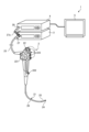
- FIG. 1 is a diagram showing a schematic diagram of an overall configuration of an endoscope system according to an embodiment.
- the endoscope system 1 shown in Fig. 1 captures images of the inside of a subject's body by inserting an insertion portion of an endoscope into a body cavity or lumen of a subject such as a patient, and displays a display image based on the captured image signal on a display device.
- the endoscope system 1 includes an endoscope 2, a light source device 3, a control device 4, and a display device 5.
- the endoscope 2 generates an imaging signal (RAW data) by imaging the inside of the subject's body, and outputs the generated imaging signal to the control device 4. Specifically, the endoscope 2 generates a first imaging signal by irradiating excitation light and imaging fluorescence, and a second imaging signal by irradiating narrowband light and imaging.
- the endoscope 2 includes an insertion section 21, an operation section 22, and a universal cord 23.
- the insertion section 21 is inserted into the subject.
- the insertion section 21 has a flexible, elongated shape.
- the insertion section 21 has a tip section 24 that incorporates an imaging element (described later), a freely bendable bending section 25 composed of multiple bending pieces, and a long, flexible flexible tube section 26 that is connected to the base end side of the bending section 25.
- the tip 24 is made of glass fiber or the like.
- the tip 24 forms a light guide path for the illumination light supplied from the control device 4 via the universal cord 23 and the operation unit 22, and also generates an image signal capturing the return light of the illumination light and outputs it to the control device 4.
- the operation unit 22 has a bending knob 221 for bending the bending portion 25 in the up-down and left-right directions, a treatment tool insertion portion 222 for inserting a treatment tool, and a plurality of switches 223 which are an operation input portion for inputting, in addition to the control device 4, operation instruction signals for peripheral devices such as an air supply means, a water supply means, and a gas supply means, a pre-freeze signal for instructing the endoscope system 1 to take still images, or a switching signal for switching the observation mode of the endoscope system 1.
- the treatment tool inserted from the treatment tool insertion portion 222 passes through a treatment tool channel (not shown) in the tip portion 24 and emerges from an opening (not shown).
- the universal cord 23 incorporates at least a light guide and a light collecting cable consisting of one or more cables.
- the collecting cable is a signal line for transmitting and receiving signals between the endoscope 2 and the control device 4, and includes a signal line for transmitting and receiving an imaging signal (RAW data) and a signal line for transmitting and receiving a timing signal (synchronization signal and clock signal) for driving the imaging element described below.
- the universal cord 23 has a connector section 27 that is detachable from the control device 4, and a connector section 28 at the extended end of the coiled cable 27a that is detachable from the control device 4.
- the light source device 3 irradiates the biological tissue with excitation light and also irradiates the biological tissue with narrowband light having a wavelength determined according to the absorption rate of hemoglobin.
- the light source device 3 is connected to one end of the light guide of the endoscope 2, and supplies illumination light to be irradiated into the subject to the one end of the light guide under the control of the control device 4.
- the light source device 3 is realized using one or more light sources, such as a light emitting diode (LED) light source, a xenon lamp, and a semiconductor laser element such as a laser diode (LD), a processor that is a processing device having hardware such as a field programmable gate array (FPGA) or a central processing unit (CPU), and a memory that is a temporary storage area used by the processor.
- the light source device 3 and the control device 4 may be configured to communicate individually as shown in FIG. 1, or may be integrated.
- the control device 4 controls each component of the endoscope system 1.
- the control device 4 supplies illumination light for the endoscope 2 to irradiate the subject.
- the control device 4 also performs various types of image processing on the imaging signal input from the endoscope 2 and outputs the signal to the display device 5.
- the display device 5 under the control of the control device 4, displays an image based on a video signal input from the control device 4.
- the display device 5 is realized using a display panel such as an organic EL (Electro Luminescence) panel or a liquid crystal panel.
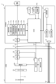
- Fig. 2 is a block diagram showing the functional configuration of the main parts of the endoscope system 1.
- the endoscope 2 includes an illumination optical system 201, an imaging optical system 202, a cut filter 203, an imaging element 204, an A/D conversion unit 205, a P/S conversion unit 206, an imaging recording unit 207, and an imaging control unit 208.
- Each of the illumination optical system 201, the imaging optical system 202, the cut filter 203, the imaging element 204, the A/D conversion unit 205, the P/S conversion unit 206, the imaging recording unit 207, and the imaging control unit 208 is disposed within the tip portion 24.
- the illumination optical system 201 irradiates the subject (biological tissue) with illumination light supplied from a light guide 231 formed of an optical fiber or the like.
- the illumination optical system 201 is realized using one or more lenses or the like.
- the imaging optical system 202 focuses light such as reflected light from the subject, return light from the subject, and fluorescence emitted by the subject, to form an image of the subject (light rays) on the light receiving surface of the image sensor 204.
- the imaging optical system 202 is realized using one or more lenses, etc.
- the cut filter 203 is disposed on the optical axis O1 between the imaging optical system 202 and the imaging element 204.
- the cut filter 203 blocks light in the wavelength band of the excitation light reflected or returned from the subject, which is supplied from the control device 4 described later, and transmits light in a wavelength band longer than the wavelength band of the excitation light.
- the cut filter 203 also transmits light in the wavelength band of the narrowband light reflected or returned from the subject, which is supplied from the control device 4 described later.
- the imaging element 204 Under the control of the imaging control unit 208, the imaging element 204 receives the subject image (light rays) formed by the imaging optical system 202 and transmitted through the cut filter 203, performs photoelectric conversion to generate an imaging signal (RAW data), and outputs it to the A/D conversion unit 205.
- the imaging element 204 is realized using a CCD (Charge Coupled Device) or CMOS (Complementary Metal Oxide Semiconductor) image sensor in which one of the color filters constituting a Bayer array (RGGB) is arranged on each of a plurality of pixels arranged in a two-dimensional matrix.
- CCD Charge Coupled Device
- CMOS Complementary Metal Oxide Semiconductor
- the A/D conversion unit 205 Under the control of the imaging control unit 208, the A/D conversion unit 205 performs A/D conversion processing on the analog imaging signal input from the imaging element 204 and outputs the result to the P/S conversion unit 206.
- the A/D conversion unit 205 is realized using an A/D conversion circuit, etc.
- the P/S conversion unit 206 performs parallel/serial conversion on the digital imaging signal input from the A/D conversion unit 205 under the control of the imaging control unit 208, and outputs the parallel/serial converted imaging signal to the control device 4 via the first transmission cable 232.
- the P/S conversion unit 206 is realized using a P/S conversion circuit or the like. Note that in the first embodiment, instead of the P/S conversion unit 206, an E/O conversion unit that converts the imaging signal into an optical signal may be provided, and the imaging signal may be output to the control device 4 by the optical signal, or the imaging signal may be transmitted to the control device 4 by wireless communication such as Wi-Fi (Wireless Fidelity) (registered trademark).
- Wi-Fi Wireless Fidelity
- the imaging and recording unit 207 records various information related to the endoscope 2 (e.g., pixel information of the imaging element 204, characteristics of the cut filter 203).
- the imaging and recording unit 207 also records various setting data and control parameters transmitted from the control device 4 via the second transmission cable 233.
- the imaging and recording unit 207 is configured using a non-volatile memory and a volatile memory.
- the imaging control unit 208 controls the operation of the imaging element 204, the A/D conversion unit 205, and the P/S conversion unit 206 based on the setting data received from the control device 4 via the second transmission cable 233.
- the imaging control unit 208 is realized using a TG (Timing Generator), a processor which is a processing device having hardware such as a CPU, and a memory which is a temporary storage area used by the processor.
- the light source device 3 includes a condenser lens 30 , a first light source unit 31 , a second light source unit 32 , and a light source control unit 33 .
- the focusing lens 30 focuses the light emitted by each of the first light source unit 31 and the second light source unit 32 and emits the light to the light guide 231.
- the focusing lens 30 is composed of one or more lenses.
- the first light source unit 31 emits narrowband light under the control of the light source control unit 33 to supply narrowband light to the light guide 231.
- the narrowband light is, for example, amber light having a peak wavelength in the wavelength band of 580 nm to 620 nm, but may also be blue-violet light having a peak wavelength in the wavelength band of 390 nm to 430 nm, or green light having a peak wavelength in the wavelength band of 500 nm to 550 nm, and may include light of two or more wavelength bands.
- the first light source unit 31 is configured using a collimating lens, an LED (Light Emitting Diode) or an LD (Laser Diode), a driver, etc.
- the second light source unit 32 emits excitation light having a predetermined wavelength band under the control of the light source control unit 33, thereby supplying narrowband light as illumination light to the light guide 231.
- the excitation light has a wavelength that excites substances such as advanced glycation end products (AGEs) contained in the thermally denatured region, and has a wavelength band of, for example, 400 nm to 430 nm (center wavelength 415 nm).
- the thermally denatured region is a region in which biological tissue is denatured by heat as a result of thermal treatment performed by an energy device such as a high-frequency knife.
- the excitation light irradiated by the second light source unit 32 is blocked by the cut filter 203, and the fluorescence (wavelength 540 nm) generated from the AGEs passes through the cut filter 203, so that a fluorescent image can be captured.
- the second light source unit 32 is realized using a collimating lens, a semiconductor laser such as a violet LD (Laser Diode), a driver, etc.
- the light source control unit 33 is configured using a processor, which is a processing device having hardware such as an FPGA (Field-Programmable Gate Array) or a CPU (Central Processing Unit), and a memory, which is a temporary storage area used by the processor.
- the light source control unit 33 controls the light emission timing, light emission intensity, light emission time, etc. of each of the first light source unit 31 and the second light source unit 32 based on control data input from the control unit 405.
- the control device 4 includes an S/P conversion unit 401 , an image processing unit 402 , an input unit 403 , a recording unit 404 , and a control unit 405 .
- the S/P conversion unit 401 performs serial/parallel conversion on the imaging signal received from the endoscope 2 via the first transmission cable 232 and outputs it to the image processing unit 402.
- the endoscope 2 outputs the imaging signal as an optical signal
- an O/E conversion unit that converts the optical signal into an electrical signal may be provided instead of the S/P conversion unit 401.
- a communication module capable of receiving wireless signals may be provided instead of the S/P conversion unit 401.
- the image processing unit 402 is realized by using a processor having hardware such as a CPU, a GPU (Graphics Processing Unit) or an FPGA, and a memory that is a temporary storage area used by the processor. Under the control of the control unit 405, the image processing unit 402 performs a predetermined image processing on the imaging signal input from the S/P conversion unit 401 and outputs the result to the display device 5. In one embodiment, the image processing unit 402 functions as a support device and an image processing device. The image processing unit 402 generates a fluorescent image from the first imaging signal and generates a narrowband light observation image from the second imaging signal.
- the image processing unit 402 has an image generation unit 402a, a thermal denaturation region extraction unit 402b, a blood vessel region extraction unit 402c, an adjustment unit 402d, a calculation unit 402e, and an output unit 402f.
- the image generating unit 402a generates a fluorescence image from a first imaging signal obtained by capturing fluorescence by irradiating excitation light from the second light source unit 32.
- the image generating unit 402a also generates a narrowband light observation image from a second imaging signal obtained by irradiating narrowband light from the first light source unit 31.
- the thermally altered region extraction unit 402b extracts a thermally altered region from a fluorescence image captured by irradiating excitation light onto biological tissue.
- the thermally altered region extraction unit 402b extracts, as a thermally altered region, a region whose brightness is equal to or exceeds a threshold value due to fluorescence generated by AGEs from a fluorescence image captured by irradiating excitation light onto biological tissue.
- the blood vessel region extraction unit 402c extracts blood vessel regions from narrowband light observation images captured by irradiating biological tissue with narrowband light of a wavelength determined according to the absorption rate of hemoglobin. For example, amber light has a higher absorption rate in hemoglobin than red light, has a longer wavelength than green light, and reaches deeper, making it easier to observe deep blood vessels than with normal light. In the narrowband light observation image captured by irradiating amber light, the blood vessel region extraction unit 402c extracts, as deep blood vessel regions, regions where the brightness of the amber light is below a threshold due to absorption by hemoglobin.
- the adjustment unit 402d aligns the fluorescent image and the narrowband light observation image.
- the adjustment unit 402d aligns the positions of feature points in the fluorescent image (characteristic points of the image, such as the edge of a lesion or a bleeding point) and feature points in the narrowband light observation image so that their positions correspond to each other.
- the adjustment unit 402d may also extract feature information from a first reference image captured by irradiating a reference light, which is narrowband light with a wavelength different from the narrowband light, under the imaging conditions under which the fluorescent image was captured, and a second reference image captured by irradiating a reference light under the imaging conditions under which the narrowband light observation image was captured, and align the fluorescent image and the narrowband light observation image based on the feature information.
- the wavelength of the reference light is not particularly limited.
- the feature information is, for example, position information of the feature points.
- the calculation unit 402e calculates the distance between the thermally denatured region and the blood vessel region.
- the output unit 402f outputs information according to the distance between the thermally denatured region and the blood vessel region.
- the output unit 402f outputs, for example, a display control signal superimposed on a display image that causes the display device 5 to display the distance between the thermally denatured region and the blood vessel region.
- the output unit 402f may also output information notifying that the distance between the thermally denatured region and the blood vessel region is equal to or less than a threshold value. For example, when the distance between the thermally denatured region and the blood vessel region is equal to or less than a threshold value, the output unit 402f may output a display control signal that notifies by superimposing a warning using a color or mark on a display image that is displayed on the display device 5.
- the input unit 403 receives inputs of various operations related to the endoscope system 1 and outputs the received operations to the control unit 405.
- the input unit 403 is configured using a mouse, a foot switch, a keyboard, buttons, switches, a touch panel, etc.
- the recording unit 404 is realized using a recording medium such as a volatile memory, a non-volatile memory, an SSD (Solid State Drive), an HDD (Hard Disk Drive), or a memory card.
- the recording unit 404 records data including various parameters necessary for the operation of the endoscope system 1.
- the recording unit 404 also has a program recording unit 404a that records various programs for operating the endoscope system 1.
- the control unit 405 is realized using a processor having hardware such as an FPGA or a CPU, and a memory that is a temporary storage area used by the processor.
- the control unit 405 comprehensively controls each part that constitutes the endoscope system 1.
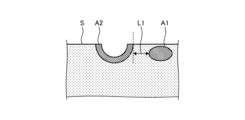
- FIG. 3 is a diagram showing an example of a biological tissue of a subject.
- the subject has a blood vessel region A1.
- a thermal treatment such as lesion resection is performed on a surface S of the biological tissue of the subject by an energy device, the resection surface is denatured by heat, and a thermally denatured region A2 is formed.
- the control device 4 causes the display device 5 to display a distance L1 between the blood vessel region A1 and the thermally denatured region A2 in the horizontal direction (the direction along the surface S) will be described.
- FIG. 4 is a flowchart showing an outline of the processing executed by the control device.
- the image generating unit 402a generates a narrowband light observation image from a second imaging signal captured by irradiating narrowband light from the first light source unit 31 onto biological tissue (step S1).
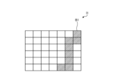
- FIG. 5 is a diagram showing an example of a narrowband light observation image. As shown in FIG. 5, the vascular region extraction unit 402c extracts pixels that are deemed to be a hatched vascular region B1 in the narrowband light observation image I1. The vascular region extraction unit 402c extracts pixels in the narrowband light observation image I1 whose brightness is below a threshold due to absorption by hemoglobin as the vascular region B1.
- the image generating unit 402a generates a fluorescence image from the first imaging signal obtained by irradiating the biological tissue with excitation light from the second light source unit 32 and capturing the fluorescence (step S3).
- the thermally altered region extraction unit 402b extracts the thermally altered region from the fluorescence image obtained by irradiating the biological tissue with excitation light and capturing the fluorescence (step S4).
- FIG. 6 is a diagram showing an example of a fluorescence image. As shown in FIG. 6, the thermally altered region extraction unit 402b extracts pixels that are deemed to be the thermally altered region B2, which is hatched, in the fluorescence image I2. The thermally altered region extraction unit 402b extracts pixels in the fluorescence image I2 whose brightness is equal to or exceeds a threshold value due to fluorescence from AGEs as the thermally altered region B2.
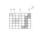
- FIG. 7 is a diagram showing an image in which the narrowband light observation image and the fluorescence image are superimposed. As shown in FIG. 7, the adjustment unit 402d generates a superimposed image I3 in which the narrowband light observation image I1 and the fluorescence image I2 are superimposed such that the positions of the feature points in the narrowband light observation image I1 and the feature points in the fluorescence image I2 overlap.
- the calculation unit 402e calculates the distance between the thermally denatured region B2 and the blood vessel region B1 (step S6).
- the distance L2 corresponds to the size of one pixel in the superimposed image I3.
- the calculation unit 402e calculates the distance L1 using the distance L2. In other words, the calculation unit 402e estimates the actual distance between the thermally denatured region and the blood vessels of the subject from the distance L1 between the blood vessel region B1 and the thermally denatured region B2 in the superimposed image I3.
- the output unit 402f outputs information according to the distance between the thermally denatured region B2 and the blood vessel region B1 (step S7).
- the output unit 402f outputs, for example, a display control signal that causes the display device 5 to display the distance between the thermally denatured region B2 and the blood vessel region B1.
- information according to the distance between the thermally altered region B2 and the blood vessel region B1 is output based on the narrowband light observation image I1 and the fluorescence image I2, so the surgeon can easily recognize the distance between the region that has been subjected to thermal treatment and the blood vessel.
- FIG. 8 is a diagram showing an example of a biological tissue of a subject. As shown in Fig. 8, a blood vessel region A11 is present deep inside the subject. When a thermal treatment such as lesion resection is performed on the surface S of the biological tissue of the subject by an energy device, the resection surface is denatured by heat, and a thermally denatured region A12 is formed. At this time, the control device 4 may cause the display device 5 to display the depthwise distance L11 between the blood vessel region A11 and the thermally denatured region A12.
- the depthwise direction means a direction perpendicular to the surface S of the biological tissue.
- the calculation unit 402e calculates the depth of the thermally altered region A12 from the fluorescent image. Since there is a correlation between the depth of the thermally altered region A12 and the brightness of the fluorescent image, the calculation unit 402e can estimate the depth of the thermally altered region A12 from the brightness of the fluorescent image based on the correlation obtained in advance by measurement.
- the calculation unit 402e also extracts the depth of the vascular region A11 from the narrowband light observation image.
- the calculation unit 402e extracts the deep vascular region from a first narrowband light observation image captured by irradiating amber light as the narrowband light, extracts the mid-layer vascular region from a second narrowband light observation image captured by irradiating green light as the narrowband light, and extracts the superficial vascular region from a third narrowband light observation image captured by irradiating blue-violet light as the narrowband light.
- the calculation unit 402e can then estimate the depth of the vascular region A11 from the deep to superficial vascular regions.
- the calculation unit 402e calculates the distance in the depth direction between the thermally altered region A12 and the blood vessel region A11.
- the output unit 402f outputs information according to the distance L11 between the thermally denatured region A12 and the blood vessel region A11.
- the output unit 402f outputs, for example, a display control signal that causes the display device 5 to display the distance L11 in the depth direction between the thermally denatured region A12 and the blood vessel region A11.
- information corresponding to the depthwise distance L11 between the thermally altered area A12 and the blood vessel area A11 is output based on the narrowband light observation image and the fluorescence image, so the surgeon can easily recognize the distance between the area that has been subjected to thermal treatment and the blood vessel.
- the adjustment unit 402d may extract feature information from a first reference image captured by irradiating reference light, which is narrowband light with a wavelength different from the narrowband light, under the imaging conditions under which the fluorescent image was captured, and a second reference image captured by irradiating reference light under the imaging conditions under which the narrowband light observation image was captured, and align the fluorescent image and narrowband light observation image based on the feature information.
- the wavelength of the reference light is not particularly limited.
- the feature information is, for example, position information of a feature point.
- the vascular region extraction unit 402c may also extract a deep vascular region from a first narrowband light observation image captured by irradiating amber light as the narrowband light, extract a mid-layer vascular region from a second narrowband light observation image captured by irradiating green light as the narrowband light, and extract a superficial vascular region from a third narrowband light observation image captured by irradiating blue-violet light as the narrowband light.
- the output unit 402f outputs information corresponding to two or more of the distance between the thermally denatured region and the deep vascular region, the distance between the thermally denatured region and the middle vascular region, or the distance between the thermally denatured region and the superficial vascular region.
- the surgeon can recognize the distance between the thermally denatured region and the vascular region in two or more layers selected from the deep to superficial layers.
- the output unit 402f may also output information corresponding to one distance selected from the distance between the thermally denatured region and the deep vascular region, the distance between the thermally denatured region and the mid-layer vascular region, or the distance between the thermally denatured region and the superficial vascular region. As a result, the surgeon can recognize the distance between the thermally denatured region and the vascular region in one selected layer from the deep to superficial layers.
- the control unit 405 may also have a function as a learning unit of a learning device.
- the control unit 405 may generate a trained model by machine learning using teacher data in which a fluorescent image obtained by irradiating excitation light to a biological tissue and capturing fluorescence and a narrowband light observation image obtained by irradiating a biological tissue with narrowband light having a wavelength determined according to the absorption rate of hemoglobin are input data, and information corresponding to the distance between the thermally denatured region extracted from the fluorescent image and the blood vessel region extracted from the narrowband light observation image is output data.
- the trained model is composed of a neural network in which each layer has one or more nodes.
- the type of machine learning is not particularly limited, but it is sufficient that, for example, teacher data and training data in which fluorescent images and narrowband light observation images of multiple subjects are associated with the distance between the thermally denatured region and the blood vessel region calculated from the multiple fluorescent images and narrowband light observation images are prepared, and the teacher data and training data are input into a calculation model based on a multilayer neural network for training.
- a machine learning technique for example, a technique based on a deep neural network (DNN), which is a multi-layer neural network such as a convolutional neural network (CNN) or a 3D-CNN, may be used.
- DNN deep neural network
- CNN convolutional neural network
- 3D-CNN 3D-CNN
- a technique based on a recurrent neural network (RNN) or long short-term memory units (LSTM), which is an extension of an RNN may also be used.
- RNN recurrent neural network
- LSTM long short-term memory units
- a learning unit of a learning device different from the control device 4 may execute these functions.
Landscapes
- Engineering & Computer Science (AREA)
- Health & Medical Sciences (AREA)
- Physics & Mathematics (AREA)
- Life Sciences & Earth Sciences (AREA)
- Computer Vision & Pattern Recognition (AREA)
- General Physics & Mathematics (AREA)
- Theoretical Computer Science (AREA)
- General Health & Medical Sciences (AREA)
- Nuclear Medicine, Radiotherapy & Molecular Imaging (AREA)
- Medical Informatics (AREA)
- Surgery (AREA)
- Radiology & Medical Imaging (AREA)
- Quality & Reliability (AREA)
- Molecular Biology (AREA)
- Biomedical Technology (AREA)
- Heart & Thoracic Surgery (AREA)
- Animal Behavior & Ethology (AREA)
- Public Health (AREA)
- Veterinary Medicine (AREA)
- Pathology (AREA)
- Optics & Photonics (AREA)
- Biophysics (AREA)
- Plasma & Fusion (AREA)
- Otolaryngology (AREA)
- Endoscopes (AREA)
Abstract
Description
図1は、一実施の形態に係る内視鏡システムの全体構成を模式的に示す図である。図1に示す内視鏡システム1は、患者等の被検体の体腔や管腔内へ内視鏡の挿入部を挿入することによって被検体の体内を撮像し、この撮像した撮像信号に基づく表示画像を表示装置に表示する。内視鏡システム1は、内視鏡2と、光源装置3と、制御装置4と、表示装置5と、を備える。
まず、内視鏡2の構成について説明する。
内視鏡2は、被検体の体内を撮像した撮像信号(RAWデータ)を生成し、この生成した撮像信号を制御装置4へ出力する。具体的には、内視鏡2は、励起光を照射して蛍光を撮像した第1撮像信号、及び狭帯域光を照射して撮像した第2撮像信号を生成する。内視鏡2は、挿入部21と、操作部22と、ユニバーサルコード23と、を備える。
次に、光源装置の構成について説明する。
光源装置3は、励起光を生体組織に照射するとともに、ヘモグロビンの吸収率に応じて定めた波長の狭帯域光を生体組織に照射する。光源装置3は、内視鏡2のライトガイドの一端が接続され、制御装置4による制御のもと、ライトガイドの一端に被検体内に照射する照明光を供給する。光源装置3は、LED(Light Emitting Diode)光源、キセノンランプ及びLD(laser Diode)等の半導体レーザ素子のいずれかの1つ以上の光源と、FPGA(Field Programmable Gate Array)やCPU(Central Processing Unit)等のハードウェアを有する処理装置であるプロセッサと、プロセッサが使用する一時的な記憶域であるメモリを用いて実現される。なお、光源装置3及び制御装置4は、図1に示すように個別に通信する構成をしてもよいし、一体化した構成であってもよい。
次に、制御装置4の構成について説明する。
制御装置4は、内視鏡システム1の各部を制御する。制御装置4は、内視鏡2が被検体に照射するための照明光を供給する。また、制御装置4は、内視鏡2から入力された撮像信号に対して、各種の画像処理を行って表示装置5へ出力する。
次に、表示装置5の構成について説明する。
表示装置5は、制御装置4の制御のもと、制御装置4から入力された映像信号に基づく表示画像を表示する。表示装置5は、有機EL(Electro Luminescence)や液晶等の表示パネルを用いて実現される。
次に、上述した内視鏡システム1の要部の機能構成について説明する。図2は、内視鏡システム1の要部の機能構成を示すブロック図である。
まず、内視鏡2の構成について説明する。
内視鏡2は、照明光学系201と、撮像光学系202と、カットフィルタ203と、撮像素子204と、A/D変換部205と、P/S変換部206と、撮像記録部207と、撮像制御部208と、を備える。なお、照明光学系201、撮像光学系202、カットフィルタ203、撮像素子204、A/D変換部205、P/S変換部206、撮像記録部207及び撮像制御部208の各々は、先端部24内に配置されてなる。
次に、光源装置3の構成について説明する。
光源装置3は、集光レンズ30と、第1の光源部31と、第2の光源部32と、光源制御部33と、を備える。
次に、制御装置4の構成について説明する。
制御装置4は、S/P変換部401と、画像処理部402と、入力部403と、記録部404と、制御部405と、を備える。
次に、制御装置4が実行する処理について説明する。
図3は、被検体の生体組織の一例を示す図である。図3に示すように、被検体には血管領域A1がある。また、被検体の生体組織の表面Sに対して、エネルギーデバイスにより病変切除等の熱処置を施すと、切除面が熱により変性し、熱変性領域A2が形成される。このとき、制御装置4が、血管領域A1と熱変性領域A2との水平方向(表面Sに沿った方向)の距離L1を表示装置5に表示させる処理を説明する。
図8は、被検体の生体組織の一例を示す図である。図8に示すように、被検体の深部には血管領域A11がある。また、被検体の生体組織の表面Sに対して、エネルギーデバイスにより病変切除等の熱処置を施すと、切除面が熱により変性し、熱変性領域A12が形成される。このとき、制御装置4が、血管領域A11と熱変性領域A12との深度方向の距離L11を表示装置5に表示させてもよい。なお、深度方向とは、生体組織の表面Sに直交する方向を意味する。
2 内視鏡
3 表示装置
4 制御装置
5 レーザ照射装置
7 表示装置
21 挿入部
22 操作部
23 ユニバーサルコード
24 先端部
25 湾曲部
26 可撓管部
27 コネクタ部
27a コイルケーブル
28 コネクタ部
30 集光レンズ
31 第1の光源部
32 第2の光源部
33 光源制御部
201 照明光学系
202 撮像光学系
203 カットフィルタ
204 撮像素子
205 A/D変換部
206 P/S変換部
207 撮像記録部
208 撮像制御部
221 湾曲ノブ
222 処置具挿入部
223 スイッチ
231 ライトガイド
232 第1の伝送ケーブル
233 第2の伝送ケーブル
401 S/P変換部
402 画像処理部
402a 画像生成部
402b 熱変性領域抽出部
402c 血管領域抽出部
402d 調整部
402e 算出部
402f 出力部
403 入力部
404 記録部
404a プログラム記録部
405 制御部
I1 狭帯域光観察画像
I2 蛍光画像
I3 重畳画像
Claims (20)
- 励起光を生体組織に照射して蛍光を撮像した蛍光画像から熱変性領域を抽出する熱変性領域抽出部と、
ヘモグロビンの吸収率に応じて定めた波長の狭帯域光を生体組織に照射して撮像した狭帯域光観察画像から血管領域を抽出する血管領域抽出部と、
前記熱変性領域と前記血管領域との距離に応じた情報を出力する出力部と、
を備える支援装置。 - 前記励起光は、前記熱変性領域が含有する物質を励起する波長である請求項1に記載の支援装置。
- 前記狭帯域光は、琥珀色光である請求項1に記載の支援装置。
- 前記狭帯域光は、青紫光である請求項1に記載の支援装置。
- 前記狭帯域光は、緑色光である請求項1に記載の支援装置。
- 前記熱変性領域と前記血管領域との距離を算出する算出部を備える請求項1に記載の支援装置。
- 前記蛍光画像と前記狭帯域光観察画像との位置合わせを行う調整部を備える請求項1に記載の支援装置。
- 前記調整部は、前記蛍光画像を撮像した撮像条件のもと、前記狭帯域光とは異なる波長の狭帯域光である基準光を照射して撮像した第1基準画像と、前記狭帯域光観察画像を撮像した撮像条件のもと、前記基準光を照射して撮像した第2基準画像と、における特徴情報を抽出し、前記特徴情報に基づいて、前記蛍光画像と前記狭帯域光観察画像との位置合わせを行う請求項7に記載の支援装置。
- 前記血管領域抽出部は、
前記狭帯域光として琥珀色光を照射して撮像した第1狭帯域光観察画像から深層血管領域を抽出し、
前記狭帯域光として緑色光を照射して撮像した第2狭帯域光観察画像から中層血管領域を抽出し、
前記狭帯域光として青紫光を照射して撮像した第3狭帯域光観察画像から表層血管領域を抽出する請求項8に記載の支援装置。 - 前記出力部は、前記熱変性領域と前記深層血管領域との距離、前記熱変性領域と前記中層血管領域との距離、又は、前記熱変性領域と前記表層血管領域との距離のうち、いずれか2つ以上の距離に応じた情報を出力する請求項9に記載の支援装置。
- 前記出力部は、前記熱変性領域と前記深層血管領域との距離、前記熱変性領域と前記中層血管領域との距離、又は、前記熱変性領域と前記表層血管領域との距離から選択された1つの距離に応じた情報を出力する請求項9に記載の支援装置。
- 前記熱変性領域抽出部は、前記蛍光画像において前記熱変性領域とみなす画素を抽出し、
前記血管領域抽出部は、前記狭帯域光観察画像において前記血管領域とみなす画素を抽出し、
前記算出部は、前記熱変性領域とみなされた画素と前記血管領域とみなされた画素との間の最短距離を算出する請求項6に記載の支援装置。 - 前記算出部は、
前記蛍光画像から前記熱変性領域の深度を算出し、
前記狭帯域光観察画像から前記血管領域の深度を抽出し、
前記熱変性領域と前記血管領域との深度方向における距離を算出する請求項6に記載の支援装置。 - 前記出力部は、
前記熱変性領域と前記血管領域との距離に応じた情報を表示画像上に重畳する請求項1に記載の支援装置。 - 前記出力部は、
前記熱変性領域と前記血管領域との距離を表示装置に表示させる表示制御信号を出力する請求項1に記載の支援装置。 - 前記出力部は、
前記熱変性領域と前記血管領域との距離が閾値以下であることを報知する情報を出力する請求項1に記載の支援装置。 - 熱変性領域抽出部が、励起光を生体組織に照射して蛍光を撮像した蛍光画像から熱変性領域を抽出し、
血管領域抽出部が、ヘモグロビンの吸収率に応じて定めた波長の狭帯域光を生体組織に照射して撮像した狭帯域光観察画像から血管領域を抽出し、
出力部が、前記熱変性領域と前記血管領域との距離に応じた情報を出力することを含む支援装置の作動方法。 - 励起光を生体組織に照射して蛍光を撮像した蛍光画像から熱変性領域を抽出し、
ヘモグロビンの吸収率に応じて定めた波長の狭帯域光を生体組織に照射して撮像した狭帯域光観察画像から血管領域を抽出し、
前記熱変性領域と前記血管領域との距離に応じた情報を出力することを支援装置に実行させる支援装置の作動プログラム。 - 励起光を生体組織に照射するとともに、ヘモグロビンの吸収率に応じて定めた波長の狭帯域光を生体組織に照射する光源装置と、
前記励起光を生体組織に照射して蛍光を撮像した第1撮像信号、及び前記狭帯域光を生体組織に照射して撮像した第2撮像信号を生成する内視鏡と、
前記第1撮像信号から蛍光画像を生成し、前記第2撮像信号から狭帯域光観察画像を生成する画像処理装置と、
を備え、
前記画像処理装置は、
前記蛍光画像から熱変性領域を抽出する熱変性領域抽出部と、
前記狭帯域光観察画像から血管領域を抽出する血管領域抽出部と、
前記熱変性領域と前記血管領域との距離に応じた情報を出力する出力部と、
を有する医療システム。 - 励起光を生体組織に照射して蛍光を撮像した蛍光画像と、ヘモグロビンの吸収率に応じて定めた波長の狭帯域光を生体組織に照射して撮像した狭帯域光観察画像と、を入力データとし、前記蛍光画像から抽出した熱変性領域と前記狭帯域光観察画像から抽出した血管領域との距離に応じた情報を出力データとする教師データを用いて機械学習することにより学習済みモデルを生成する学習部を備える学習装置。
Priority Applications (4)
| Application Number | Priority Date | Filing Date | Title |
|---|---|---|---|
| CN202380093519.6A CN120659571A (zh) | 2023-02-09 | 2023-02-09 | 辅助装置、辅助装置的工作方法、辅助装置的工作程序、医疗系统以及学习装置 |
| JP2024576022A JPWO2024166329A1 (ja) | 2023-02-09 | 2023-02-09 | |
| PCT/JP2023/004456 WO2024166329A1 (ja) | 2023-02-09 | 2023-02-09 | 支援装置、支援装置の作動方法、支援装置の作動プログラム、医療システム、及び学習装置 |
| US19/287,946 US20250356490A1 (en) | 2023-02-09 | 2025-08-01 | Assistance device, operation method of assistance device, computer-readable recording medium, medical system, and learning device |
Applications Claiming Priority (1)
| Application Number | Priority Date | Filing Date | Title |
|---|---|---|---|
| PCT/JP2023/004456 WO2024166329A1 (ja) | 2023-02-09 | 2023-02-09 | 支援装置、支援装置の作動方法、支援装置の作動プログラム、医療システム、及び学習装置 |
Related Child Applications (1)
| Application Number | Title | Priority Date | Filing Date |
|---|---|---|---|
| US19/287,946 Continuation US20250356490A1 (en) | 2023-02-09 | 2025-08-01 | Assistance device, operation method of assistance device, computer-readable recording medium, medical system, and learning device |
Publications (1)
| Publication Number | Publication Date |
|---|---|
| WO2024166329A1 true WO2024166329A1 (ja) | 2024-08-15 |
Family
ID=92262160
Family Applications (1)
| Application Number | Title | Priority Date | Filing Date |
|---|---|---|---|
| PCT/JP2023/004456 Ceased WO2024166329A1 (ja) | 2023-02-09 | 2023-02-09 | 支援装置、支援装置の作動方法、支援装置の作動プログラム、医療システム、及び学習装置 |
Country Status (4)
| Country | Link |
|---|---|
| US (1) | US20250356490A1 (ja) |
| JP (1) | JPWO2024166329A1 (ja) |
| CN (1) | CN120659571A (ja) |
| WO (1) | WO2024166329A1 (ja) |
Citations (3)
| Publication number | Priority date | Publication date | Assignee | Title |
|---|---|---|---|---|
| JP2012130506A (ja) * | 2010-12-21 | 2012-07-12 | Fujifilm Corp | 光計測システムおよび光計測方法 |
| WO2021176737A1 (ja) * | 2020-03-06 | 2021-09-10 | オリンパス株式会社 | 医療用観察システムおよび医療用撮像装置 |
| JP2021529633A (ja) * | 2018-07-16 | 2021-11-04 | エシコン エルエルシーEthicon LLC | 外科用可視化プラットフォーム |
-
2023
- 2023-02-09 WO PCT/JP2023/004456 patent/WO2024166329A1/ja not_active Ceased
- 2023-02-09 JP JP2024576022A patent/JPWO2024166329A1/ja active Pending
- 2023-02-09 CN CN202380093519.6A patent/CN120659571A/zh active Pending
-
2025
- 2025-08-01 US US19/287,946 patent/US20250356490A1/en active Pending
Patent Citations (3)
| Publication number | Priority date | Publication date | Assignee | Title |
|---|---|---|---|---|
| JP2012130506A (ja) * | 2010-12-21 | 2012-07-12 | Fujifilm Corp | 光計測システムおよび光計測方法 |
| JP2021529633A (ja) * | 2018-07-16 | 2021-11-04 | エシコン エルエルシーEthicon LLC | 外科用可視化プラットフォーム |
| WO2021176737A1 (ja) * | 2020-03-06 | 2021-09-10 | オリンパス株式会社 | 医療用観察システムおよび医療用撮像装置 |
Also Published As
| Publication number | Publication date |
|---|---|
| US20250356490A1 (en) | 2025-11-20 |
| JPWO2024166329A1 (ja) | 2024-08-15 |
| CN120659571A (zh) | 2025-09-16 |
Similar Documents
| Publication | Publication Date | Title |
|---|---|---|
| US12171399B2 (en) | Surgical devices, systems, and methods using multi-source imaging | |
| US20230000330A1 (en) | Medical observation system, medical imaging device and imaging method | |
| JPWO2018159363A1 (ja) | 内視鏡システム及びその作動方法 | |
| US20230248209A1 (en) | Assistant device, endoscopic system, assistant method, and computer-readable recording medium | |
| US20230102358A1 (en) | Surgical devices, systems, and methods using fiducial identification and tracking | |
| US20230092920A1 (en) | Systems and methods of analyzing a kidney stone | |
| US20230000329A1 (en) | Medical image processing device, medical imaging device, medical observation system, image processing method, and computer-readable recording medium | |
| JP6203088B2 (ja) | 生体観察システム | |
| CN115607092A (zh) | 内窥镜系统、医疗图像处理装置及其工作方法 | |
| US20250356490A1 (en) | Assistance device, operation method of assistance device, computer-readable recording medium, medical system, and learning device | |
| US20250352032A1 (en) | Medical device, medical system, learning device, method of operating medical device, and computer-readable recording medium | |
| WO2024166304A1 (ja) | 画像処理装置、医療システム、画像処理装置の作動方法、及び学習装置 | |
| US20250352028A1 (en) | Medical device, medical system, learning device, method of operating medical device, and computer-readable recording medium | |
| CN115381379A (zh) | 医疗图像处理装置、内窥镜系统及医疗图像处理装置的工作方法 | |
| WO2024166311A1 (ja) | 画像処理装置、医療システム、画像処理装置の作動方法、及び学習装置 | |
| US20250359729A1 (en) | Medical device, medical system, learning device, operation method of medical device, and computer-readable recording medium | |
| US20250352026A1 (en) | Medical device, medical system, operation method of medical device, and computer-readable recording medium | |
| US20250352029A1 (en) | Medical device, medical system, operation method of medical device, and computer-readable recording medium | |
| US20250352049A1 (en) | Medical device, medical system, method of operating medical device, and computer-readable recording medium | |
| US20250359741A1 (en) | Medical device, medical system, medical device operation method, and computer-readable recording medium | |
| WO2024166325A1 (ja) | 医療用装置、内視鏡システム、制御方法、制御プログラム、及び学習装置 | |
| US20180146845A1 (en) | Marking method and resecting method | |
| WO2024166306A1 (ja) | 医療用装置、内視鏡システム、制御方法、制御プログラム、及び学習装置 | |
| WO2024166309A1 (ja) | 医療用装置、内視鏡システム、制御方法、制御プログラム、及び学習装置 |
Legal Events
| Date | Code | Title | Description |
|---|---|---|---|
| 121 | Ep: the epo has been informed by wipo that ep was designated in this application |
Ref document number: 23921160 Country of ref document: EP Kind code of ref document: A1 |
|
| ENP | Entry into the national phase |
Ref document number: 2024576022 Country of ref document: JP Kind code of ref document: A |
|
| WWE | Wipo information: entry into national phase |
Ref document number: 2024576022 Country of ref document: JP |
|
| WWE | Wipo information: entry into national phase |
Ref document number: 202380093519.6 Country of ref document: CN |
|
| NENP | Non-entry into the national phase |
Ref country code: DE |
|
| WWP | Wipo information: published in national office |
Ref document number: 202380093519.6 Country of ref document: CN |