WO2024166274A1 - タービン及びターボチャージャ - Google Patents
タービン及びターボチャージャ Download PDFInfo
- Publication number
- WO2024166274A1 WO2024166274A1 PCT/JP2023/004280 JP2023004280W WO2024166274A1 WO 2024166274 A1 WO2024166274 A1 WO 2024166274A1 JP 2023004280 W JP2023004280 W JP 2023004280W WO 2024166274 A1 WO2024166274 A1 WO 2024166274A1
- Authority
- WO
- WIPO (PCT)
- Prior art keywords
- turbine
- plate portion
- housing
- biasing
- nozzle ring
- Prior art date
- Legal status (The legal status is an assumption and is not a legal conclusion. Google has not performed a legal analysis and makes no representation as to the accuracy of the status listed.)
- Ceased
Links
Images




Classifications
-
- F—MECHANICAL ENGINEERING; LIGHTING; HEATING; WEAPONS; BLASTING
- F01—MACHINES OR ENGINES IN GENERAL; ENGINE PLANTS IN GENERAL; STEAM ENGINES
- F01D—NON-POSITIVE DISPLACEMENT MACHINES OR ENGINES, e.g. STEAM TURBINES
- F01D5/00—Blades; Blade-carrying members; Heating, heat-insulating, cooling or antivibration means on the blades or the members
- F01D5/02—Blade-carrying members, e.g. rotors
- F01D5/04—Blade-carrying members, e.g. rotors for radial-flow machines or engines
- F01D5/043—Blade-carrying members, e.g. rotors for radial-flow machines or engines of the axial inlet- radial outlet, or vice versa, type
- F01D5/046—Heating, heat insulation or cooling means
-
- F—MECHANICAL ENGINEERING; LIGHTING; HEATING; WEAPONS; BLASTING
- F01—MACHINES OR ENGINES IN GENERAL; ENGINE PLANTS IN GENERAL; STEAM ENGINES
- F01D—NON-POSITIVE DISPLACEMENT MACHINES OR ENGINES, e.g. STEAM TURBINES
- F01D9/00—Stators
- F01D9/02—Nozzles; Nozzle boxes; Stator blades; Guide conduits, e.g. individual nozzles
- F01D9/04—Nozzles; Nozzle boxes; Stator blades; Guide conduits, e.g. individual nozzles forming ring or sector
- F01D9/045—Nozzles; Nozzle boxes; Stator blades; Guide conduits, e.g. individual nozzles forming ring or sector for radial flow machines or engines
-
- F—MECHANICAL ENGINEERING; LIGHTING; HEATING; WEAPONS; BLASTING
- F02—COMBUSTION ENGINES; HOT-GAS OR COMBUSTION-PRODUCT ENGINE PLANTS
- F02B—INTERNAL-COMBUSTION PISTON ENGINES; COMBUSTION ENGINES IN GENERAL
- F02B37/00—Engines characterised by provision of pumps driven at least for part of the time by exhaust
- F02B37/12—Control of the pumps
- F02B37/24—Control of the pumps by using pumps or turbines with adjustable guide vanes
-
- F—MECHANICAL ENGINEERING; LIGHTING; HEATING; WEAPONS; BLASTING
- F01—MACHINES OR ENGINES IN GENERAL; ENGINE PLANTS IN GENERAL; STEAM ENGINES
- F01D—NON-POSITIVE DISPLACEMENT MACHINES OR ENGINES, e.g. STEAM TURBINES
- F01D11/00—Preventing or minimising internal leakage of working-fluid, e.g. between stages
- F01D11/005—Sealing means between non relatively rotating elements
-
- F—MECHANICAL ENGINEERING; LIGHTING; HEATING; WEAPONS; BLASTING
- F05—INDEXING SCHEMES RELATING TO ENGINES OR PUMPS IN VARIOUS SUBCLASSES OF CLASSES F01-F04
- F05D—INDEXING SCHEME FOR ASPECTS RELATING TO NON-POSITIVE-DISPLACEMENT MACHINES OR ENGINES, GAS-TURBINES OR JET-PROPULSION PLANTS
- F05D2220/00—Application
- F05D2220/40—Application in turbochargers
-
- F—MECHANICAL ENGINEERING; LIGHTING; HEATING; WEAPONS; BLASTING
- F05—INDEXING SCHEMES RELATING TO ENGINES OR PUMPS IN VARIOUS SUBCLASSES OF CLASSES F01-F04
- F05D—INDEXING SCHEME FOR ASPECTS RELATING TO NON-POSITIVE-DISPLACEMENT MACHINES OR ENGINES, GAS-TURBINES OR JET-PROPULSION PLANTS
- F05D2230/00—Manufacture
- F05D2230/50—Building or constructing in particular ways
- F05D2230/54—Building or constructing in particular ways by sheet metal manufacturing
-
- F—MECHANICAL ENGINEERING; LIGHTING; HEATING; WEAPONS; BLASTING
- F05—INDEXING SCHEMES RELATING TO ENGINES OR PUMPS IN VARIOUS SUBCLASSES OF CLASSES F01-F04
- F05D—INDEXING SCHEME FOR ASPECTS RELATING TO NON-POSITIVE-DISPLACEMENT MACHINES OR ENGINES, GAS-TURBINES OR JET-PROPULSION PLANTS
- F05D2240/00—Components
- F05D2240/10—Stators
- F05D2240/15—Heat shield
Definitions
- This disclosure relates to turbines and turbochargers.
- Patent Document 1 discloses a support structure in which the fixed nozzle is integrated with an annular nozzle ring that supports the fixed nozzle, and the outer peripheral end of the nozzle ring is clamped between the turbine casing and the bearing base, thereby supporting the fixed nozzle.
- the nozzle ring has an outer circumferential end that is in contact with a bearing base that is relatively cool, while an inner circumferential end that is exposed to exhaust gas that is relatively hot. This causes a temperature distribution on the inner and outer periphery of the nozzle ring, which generates relatively high thermal stress in the nozzle ring, and this may lead to thermal fatigue damage to the nozzle ring.
- a spring member that supports the nozzle ring is sometimes placed on the turbine, but it is sometimes unable to keep up with temperature changes in the exhaust gas introduced into the turbine, and the spring member's biasing force does not act on the nozzle ring.
- At least one embodiment of the present disclosure aims to provide a turbine and turbocharger that can continuously support a nozzle ring while the turbine is in operation and can reduce thermal stress occurring in the nozzle ring.
- a turbine includes: a first housing having a scroll flow passage; A turbine wheel provided on an inner circumferential side of the scroll passage; a nozzle ring including: an annular first plate portion disposed at a radial position between the scroll passage and the turbine wheel, the first plate portion having a flow path surface facing a gas flow path from the scroll passage to the turbine wheel; and at least one fixed nozzle vane protruding from the flow path surface of the first plate portion; a second housing disposed on a rear end side of the turbine wheel in an axial direction relative to the nozzle ring; a biasing device disposed between the second housing and the nozzle ring and configured to bias the nozzle ring toward a tip end of the turbine wheel in the axial direction, The biasing device has a tip-side opposing surface that faces the back surface of the turbine wheel across a gap in the axial direction of the turbine wheel, and is configured to bias the nozzle ring at a radial position on the nozzle ring where the at least
- a turbocharger includes: The turbine; and a centrifugal compressor configured to be driven by the turbine.
- At least one embodiment of the present disclosure provides a turbine and turbocharger that can continuously support the nozzle ring while the turbine is in operation and can reduce thermal stresses on the nozzle ring.
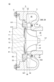
- FIG. 1 is a schematic cross-sectional view of a turbine along its axis according to an embodiment of the present disclosure
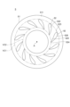
- FIG. 1 is a schematic diagram of a nozzle ring of a turbine according to an embodiment of the present disclosure, viewed from one side in the axial direction.
- FIG. FIG. 2 is a schematic cross-sectional view taken along the axis of a turbine according to a comparative example.
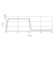
- FIG. 2 is an explanatory diagram for explaining a temperature change of a working fluid introduced into a turbine according to an embodiment of the present disclosure.
- 10 is an explanatory diagram for explaining a change in biasing force applied to a nozzle ring of a turbine according to a comparative example.
- FIG. 1 is a schematic cross-sectional view of a turbine along its axis according to an embodiment of the present disclosure
- FIG. 1 is a schematic cross-sectional view of a turbine along its axis according to an embodiment of the present disclosure
- FIG. 1 is a schematic cross-sectional view of a turbine along its axis according to an embodiment of the present disclosure
- FIG. 1 is a schematic cross-sectional view of a turbine along its axis according to an embodiment of the present disclosure
- FIG. 1 is a schematic cross-sectional view of a turbine along its axis according to an embodiment of the present disclosure
- FIG. 1 is a schematic cross-sectional view of a turbine along its axis according to an embodiment of the present disclosure
- FIG. 1 is a schematic cross-sectional view of a turbine along its axis according to an embodiment of the present disclosure
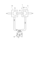
- FIG. 1 is a schematic diagram of a turbocharger according to an embodiment of the present disclosure.
- Fig. 1 is a schematic cross-sectional view along an axis line LA of a turbine 2 according to an embodiment of the present disclosure.
- the turbine 2 according to some embodiments includes a first housing (turbine housing) 3, a turbine wheel 4, a nozzle ring 5, a second housing (bearing housing) 6, and a biasing device 7.
- the second housing 6 is attached to the first housing 3 via a fastening member such as a bolt 11.
- the second housing 6 is configured to rotatably accommodate the turbine wheel 4 between the first housing 3 and the second housing 6.
- the nozzle ring 5 and the biasing device 7 are accommodated between the first housing 3 and the second housing 6.
- the direction in which the axis LA of the turbine wheel 4 extends is defined as the axial direction of the turbine wheel 4 (turbine 2)
- the direction perpendicular to the axis LA is defined as the radial direction of the turbine wheel 4 (turbine 2)
- the circumferential direction around the axis LA is defined as the circumferential direction of the turbine wheel 4 (turbine 2).
- the side where the first housing 3 is located relative to the second housing 6 (right side in FIG. 1) is defined as the leading end side
- the side where the second housing 6 is located relative to the first housing 3 opposite the leading end side, left side in FIG. 1 is defined as the rear end side.
- the turbine wheel 4 is configured to guide a working fluid (e.g., exhaust gas discharged from an internal combustion engine not shown) introduced from the outer periphery side (radially outward) of the turbine wheel 4 to the tip side of the turbine wheel 4 along the axial direction of the turbine wheel 4.
- a working fluid e.g., exhaust gas discharged from an internal combustion engine not shown
- the turbine wheel 4 includes a hub 41 having a generally truncated cone shape and a number of turbine blades 42 provided on the outer peripheral surface of the hub 41.
- Each of the turbine blades 42 is arranged at intervals from one another in the circumferential direction around the axis LA.
- the hub 41 and the turbine blades 42 are arranged so as to be rotatable integrally with the rotating shaft 12 about the axis LA.
- Each of the turbine blades 42 is arranged with a predetermined gap relative to the shroud surface 31, which is the inner surface of the first housing 3.
- the turbine wheel 4 is made of an open-type impeller that does not include an annular member surrounding the outer periphery of the turbine blades 42.
- a scroll passage 32 for guiding the working fluid for rotating the turbine wheel 4 to the turbine wheel 4, and a working fluid discharge passage 33 for discharging the working fluid that has passed through the turbine wheel 4 to the outside of the first housing 3 (turbine 2) are formed inside the first housing 3 .
- the first housing 3 has the scroll passage 32 and the working fluid discharge passage 33.
- the scroll passage 32 is provided on the outer periphery side of the turbine wheel 4 and is a spiral passage extending along the circumferential direction of the turbine wheel 4.
- the working fluid discharge passage 33 extends from the turbine wheel 4 toward the tip side along the axial direction of the turbine wheel 4.
- an internal space 34 is formed between the first housing 3 and the second housing 6, connecting the scroll passage 32 and the working fluid discharge passage 33.
- the turbine wheel 4 is accommodated in the internal space 34 so as to be rotatable relative to the first housing 3 and the second housing 6.
- the turbine wheel 4 is provided on the inner circumferential side (inner side in the radial direction) of the scroll passage 32.
- the working fluid of the turbine 2 is guided from outside the turbine 2 through the scroll passage 32 to the turbine wheel 4, and drives the turbine wheel 4 to rotate.
- the working fluid that drives the turbine wheel 4 to rotate is discharged to the outside of the first housing 3 (turbine 2) through the working fluid discharge passage 33.
- the nozzle ring 5 includes an annular first plate portion 51 and at least one fixed nozzle vane 52.
- the first plate portion 51 is disposed at a radial position between the scroll passage 32 and the turbine wheel 4.
- the first plate portion 51 forms a working fluid passage 34A from the scroll passage 32 toward the turbine wheel 4 between itself and another member (the first housing 3 in FIG. 1).
- the scroll flow passage 32 is made of a spiral flow passage provided on the outer periphery side (outside in the radial direction) of the turbine wheel 4. This spiral flow passage extends along the circumferential direction of the turbine wheel 4 so as to surround the outer periphery side of the turbine wheel 4.
- the working fluid flow passage 34A is provided between the scroll flow passage 32 and the turbine wheel 4 in the radial direction of the turbine wheel 4 so as to surround the outer periphery side of the turbine wheel 4. Specifically, it is formed on the outer periphery side of the turbine wheel 4 in the above-mentioned internal space 34.
- the first plate portion 51 has an annular flow passage surface 511 that faces the working fluid flow passage 34A on one side in the thickness direction of the first plate portion 51 (the axial direction of the turbine wheel 4), and has an annular first back surface 512 on the other side in the thickness direction of the first plate portion 51 (the side opposite to the flow passage surface 511).
- FIG. 2 is a schematic diagram of the nozzle ring 5 of the turbine 2 according to one embodiment of the present disclosure, viewed from one axial side.
- the at least one stationary nozzle vane 52 described above protrudes from the flow path surface 511 of the first plate portion 51.
- the at least one stationary nozzle vane 52 described above includes a plurality of stationary nozzle vanes 52 spaced apart from one another in the circumferential direction of the turbine wheel 4.
- Each of the multiple fixed nozzle vanes 52 is formed integrally with the first plate portion 51, and its base end portion 521, which is one end portion in the axial direction, is connected to the flow path surface 511. As a result, each of the multiple fixed nozzle vanes 52 is fixed to the flow path surface 511.
- Each of the multiple fixed nozzle vanes 52 has a tip end surface 522 formed on the opposite side (the other end portion in the axial direction) to the base end portion 521 connected to the first plate portion 51, a leading edge 523, a trailing edge 524, and an inner blade surface 525 and an outer blade surface 526 that each extend from the leading edge 523 to the trailing edge 524.
- Each of the multiple fixed nozzle vanes 52 has its trailing edge 524 located radially inward of the turbine wheel 4 relative to its leading edge 523.
- Each of the multiple fixed nozzle vanes 52 has a blade surface that faces the working fluid flow path 34A, which is formed by the leading edge 523, the trailing edge 524, the inner blade surface 525, and the outer blade surface 526.
- the first plate portion 51 is located toward the rear end of the turbine wheel 4 in the axial direction relative to the plurality of fixed nozzle vanes 52.
- the first housing 3 has a housing-side flow passage surface 35 that extends from the outer peripheral end of the shroud surface 31 toward the outside in the radial direction of the turbine wheel 4.
- the housing-side flow passage surface 35 is an annular surface that extends along the circumferential direction of the turbine wheel 4.
- the housing-side flow passage surface 35 faces the flow passage surface 511 of the first plate portion 51 in the axial direction of the turbine wheel 4, sandwiching the working fluid flow passage 34A therebetween.
- the working fluid flow passage 34A is formed by the housing-side flow passage surface 35 and the flow passage surface 511.
- the second housing 6 is disposed closer to the rear end in the axial direction of the turbine wheel 4 than the nozzle ring 5.
- the second housing 6 has an end face 61 on the tip side in the axial direction of the turbine wheel 4, and an outward protrusion 62 that protrudes outward in the radial direction of the turbine wheel 4 on the rear end side in the axial direction of the turbine wheel 4 than the end face 61.
- the biasing device 7 is disposed between the second housing 6 and the nozzle ring 5, and is configured to bias the nozzle ring 5 toward the tip side in the axial direction of the turbine wheel 4.
- the biasing device 7 has a tip-side opposing surface 71 that faces the back surface 43 of the turbine wheel 4 with a gap in the axial direction of the turbine wheel 4.
- the gap formed between the tip-side opposing surface 71 and the back surface 43 of the turbine wheel 4 is not a minimum gap that allows the tip-side opposing surface 71 and the back surface 43 to be non-contacted and allows the biasing device 7 to be placed, but is a gap that can exhibit a heat-shielding function that can inhibit heat transfer from the back surface 43 of the turbine wheel 4 to the tip-side opposing surface 71.
- the biasing device 7 is configured to bias the nozzle ring 5 at a radial position where at least one fixed nozzle vane 52 described above is present in the nozzle ring 5.
- the biasing force of the biasing device 7 that biases the nozzle ring 5 is F1.
- the biasing force F1 acts on the radial position where at least one fixed nozzle vane 52 described above is present.
- an imaginary circle that has its origin at the axis A of the nozzle ring 5 and passes through the leading edge 523 that is located on the outermost side in the radial direction among the multiple fixed nozzle vanes 52 is defined as an outer virtual circle VC1
- an imaginary circle that has its origin at the axis A of the nozzle ring 5 and passes through the trailing edge 524 that is located on the innermost side in the radial direction among the multiple fixed nozzle vanes 52 is defined as an inner virtual circle VC2.
- the radial position where at least one fixed nozzle vane 52 exists as described above means a position that is radially inward of the outer virtual circle VC1 and radially outward of the inner virtual circle VC2.
- the nozzle ring 5 is biased by the biasing device 7 so that the tip end face 522 of each of the multiple fixed nozzle vanes 52 abuts against the housing side flow path surface 35.
- the first housing 3 is configured so that only the housing side flow path surface 35 suppresses the movement of the nozzle ring 5 along the axial direction.
- the first housing 3 has a rear scroll flow passage surface that faces the rear end side of the scroll flow passage 32 in the axial direction, and has an inward protrusion 36 that extends radially inward of the turbine wheel 4.
- the outer peripheral end 53 of the first plate portion 51 of the nozzle ring 5 is located radially inward of the turbine wheel 4 relative to the inner peripheral end of the inward protrusion 36.
- the nozzle ring 5, biased by the biasing device 7, is designed so that its movement is not restricted by the inward protrusion 36 even when it moves along the axial direction of the turbine wheel 4.
- Figure 3 is a schematic cross-sectional view along the axis LA of a turbine 02 according to a comparative example.
- the turbine 02 according to the comparative example includes the first housing 3 described above, the turbine wheel 4 described above, the nozzle ring 5 described above, the second housing 6 described above, a back plate 07, and an annular seal ring 08.
- the outer peripheral end 53 of the first plate portion 51 of the nozzle ring 5 is clamped between the inward protrusion 36 of the first housing 3 and the outward protrusion 62 of the second housing 6, suppressing deformation.
- the outer peripheral end 53 of the first plate portion 51 is in contact with the second housing 6, which has a relatively low temperature.
- the inner peripheral end of the first plate portion 51 is exposed to the working fluid (exhaust gas), which has a relatively high temperature.
- the temperature distribution occurring on the inner and outer periphery of the first plate portion 51 generates relatively high thermal stress in the first plate portion 51, which may lead to thermal fatigue damage to the first plate portion 51.
- the outer diameter of the first plate portion 51 needs to be large, which may increase the cost of the parts.
- the biasing force of the back plate 07 does not act on the radial position where at least one of the fixed nozzle vanes 52 described above is present.
- the annular seal ring 08 inserted into the annular recess 37 formed in the housing side flow path surface 35 described above biases the multiple fixed nozzle vanes 52 toward the rear end side in the axial direction of the turbine wheel 4 via an annular plate that abuts against the multiple fixed nozzle vanes 52.
- the biasing force of the annular seal ring 08 biasing the nozzle ring 5 is designated as F0.
- FIG. 4 is an explanatory diagram for explaining the temperature change of the working fluid introduced into the turbine 2 according to one embodiment of the present disclosure.
- FIG. 5 is an explanatory diagram for explaining the change in the biasing force F0 applied to the nozzle ring 5 of the turbine 2 according to a comparative example.
- FIG. 6 is an explanatory diagram for explaining the change in the biasing force F1 applied to the nozzle ring 5 of the turbine 2 according to one embodiment of the present disclosure.
- the horizontal axis represents time T (T1 to T4).
- the vertical axis represents the temperature (inlet temperature) GT of the working fluid (exhaust gas) introduced into the turbine 2.
- the vertical axis represents the biasing force F0
- the vertical axis represents the biasing force F1.
- the temperature GT changes over time during operation of the turbine 2, and there are high temperature periods when the temperature is relatively high and low temperature periods when the temperature is relatively low.
- the biasing force F0 will not act effectively when the temperature GT transitions from high to low. Since the nozzle ring 5 cools down before the first housing 3, the gap between the first plate portion 51 and the housing side flow path surface 35 becomes large, and the spring force of the annular seal ring 08 may not act.
- the biasing force F1 continues to act during operation of the turbine 2, including when the temperature GT transitions from high to low.
- the biasing force F1 acts to reduce the clearance between the first housing 3 and the nozzle ring 5, reducing the clearance flow, thereby improving the performance of the turbine 2.
- the turbine 2 includes the first housing 3, the turbine wheel 4, the nozzle ring 5, the second housing 6, and the biasing device 7.
- the nozzle ring 5 is supported by the biasing device 7, which prevents the nozzle ring 5 from coming into contact with the second housing 6, which has a relatively low temperature, and thus prevents temperature distribution from occurring in the nozzle ring 5, thereby reducing thermal stress in the nozzle ring 5.
- the biasing force of the biasing device 7 acts continuously on the nozzle ring 5 while the turbine 2 is operating, so that the nozzle ring 5 can be supported continuously while the turbine 2 is operating.
- the biasing device 7 can suppress heat input from the space facing the back surface of the turbine wheel 4 to the second housing side by using the tip side opposing surface 71 that faces the back surface of the turbine wheel 4 across a gap.
- the biasing device 7 By giving the biasing device 7 a heat insulating function, an increase in the number of parts of the turbine 2 can be suppressed.
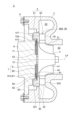
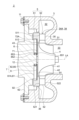
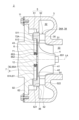
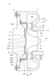
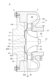
- FIG. 7 to 12 is a schematic cross-sectional view taken along the axis LA of the turbine 2 according to one embodiment of the present disclosure.
- the turbine 2 according to the embodiment shown in Figures 7 to 12 also achieves the same effects as those described for the turbine 2 according to the embodiment shown in Figure 1.
- the turbine 2 according to the embodiment shown in Figures 7 to 12 includes the first housing 3 described above, the turbine wheel 4 described above, the nozzle ring 5 described above, the second housing 6 described above, and the biasing device 7 described above.
- the first plate portion 51 described above is located axially rearward of at least one fixed nozzle vane 52, and the first back surface 512, which is the surface of the first plate portion 51 opposite the flow path surface 511, is biased by the biasing device 7.
- the area over which the biasing force acts can be made larger than when at least one fixed nozzle vane 52 is biased by the biasing device 7. This allows the biasing force of the biasing device 7 to be continuously and stably applied to the nozzle ring 5 while the turbine 2 is in operation.
- the first plate portion 51 described above is located axially forward of at least one fixed nozzle vane 52, and the tip end surface 522 formed on the opposite side to the base end portion 521 connected to the first plate portion 51 of at least one fixed nozzle vane 52 is biased by the biasing device 7.
- annular recess 38 is formed in the first housing 3.
- a first plate portion 51 is inserted into the annular recess 38, and a first back surface 512 of the first plate portion 51 abuts against the bottom surface of the annular recess 38.
- the flow path surface 511 is connected to the outer peripheral end of the shroud surface 31.
- the first plate portion 51 closer to the forward end than at least one fixed nozzle vane 52, it is possible to prevent the nozzle ring 5 from coming into contact with the second housing 6, which has a relatively low temperature, and thus prevent a temperature distribution from occurring in the nozzle ring 5, thereby reducing the thermal stress occurring in the nozzle ring 5.
- the above-mentioned biasing device 7 includes a first biasing member (disc spring) 81, as shown in FIG. 1.
- the first biasing member 81 is formed in an annular shape having the above-mentioned tip-side opposing surface 71 and an abutment portion 72 that abuts against the first back surface 512 of the first plate portion 51 on the outer circumferential side of the tip-side opposing surface 71.
- the first biasing member 81 is configured to bias the first plate portion 51 toward the tip side in the axial direction.
- the abutment portion 72 is provided at a radial position where the above-mentioned at least one fixed nozzle vane 52 is present.
- the first biasing member 81 has an inner peripheral end that abuts against the end face 61 of the second housing 6 described above, and exerts an elastic force along the axial direction of the turbine wheel 4. This elastic force acts as the biasing force described above.
- the number of parts of the turbine 2 can be reduced compared to the turbine 02 according to the comparative example, thereby reducing the cost of the turbine 2.
- the above-mentioned biasing device 7 includes a heat shield 9 and a second biasing member 82, as shown in Figures 7 to 10.
- the heat shield 9 has the above-mentioned tip-side opposing surface 71 and an abutment surface 72A that abuts against the first back surface 512 of the first plate portion 51 on the outer circumferential side of the tip-side opposing surface 71.
- the heat shield 9 is formed in a disk shape, and a front end side surface 91 on one side in the thickness direction (the front end side in the axial direction) includes the tip-side opposing surface 71 and the abutment surface 72A.
- the second biasing member 82 is disposed between the second housing 6 and the heat shield 9, and is configured to bias the heat shield 9 toward the tip side in the axial direction.
- the abutment surface 72A is provided at a radial position where at least one of the above-mentioned fixed nozzle vanes 52 is present.
- the heat shield 9 has the above-mentioned heat shielding function
- the second biasing member 82 has the above-mentioned biasing function.
- the heat shield 9 exerts its heat shielding function to suppress heat input to the second biasing member 82, thereby suppressing fatigue and damage caused by heat and deterioration of the biasing function of the second biasing member 82. This allows the biasing force of the biasing device 7 to be continuously and stably applied to the nozzle ring 5 while the turbine 2 is in operation.
- the second housing 6 described above has a rear end facing surface 61A that faces a second back surface 92, which is the surface opposite to the abutment surface 72A (front end side surface 91) of the heat shield 9, with a gap therebetween.
- the rear end facing surface 61A is a part of the end surface 61 described above.
- the second biasing member 82 described above includes disc springs 84, 84A that abut against the second back surface 92 of the heat shield 9 and the rear end facing surface 61A of the second housing 6, respectively, as shown in Figs. 7 and 8.
- the coned disc spring 84 has an outer peripheral end that abuts against the second rear surface 92 of the heat shield 9, and an inner peripheral end that abuts against the rear end facing surface 61A of the second housing 6.
- the coned disc spring 84A has an inner peripheral end that abuts against the second rear surface 92 of the heat shield 9, and an outer peripheral end that abuts against the rear end facing surface 61A of the second housing 6.
- the coned disc springs 84, 84A exert an elastic force along the axial direction of the turbine wheel 4. This elastic force acts as the above-mentioned biasing force via the heat shield 9.
- the heat shield 9 is biased by the elastic force of the disc springs 84, 84A, and biases the nozzle ring 5 at the contact surface 72A.
- the relatively inexpensive disc springs 84, 84A perform the biasing function for biasing the nozzle ring 5, the cost of the turbine 2 can be reduced.
- the second biasing member 82 described above includes annular elastic seal members 85, 85A as shown in Figures 9 and 10.
- the annular elastic seal members 85, 85A include a first biasing plate portion 851 that abuts against the second rear surface 92 of the heat shield 9, a second biasing plate portion 852 that abuts against the rear end side opposing surface 61A of the second housing 6, and a connection portion 853 that connects the outer circumferential end of the first biasing plate portion 851 and the outer circumferential end of the second biasing plate portion 852.
- the elastic seal member 85 is a C-ring with a C-shaped cross section.
- the elastic seal member 85A is an E-ring with an E-shaped cross section.
- the elastic seal members 85, 85A exert an elastic force along the axial direction of the turbine wheel 4. This elastic force acts as the above-mentioned biasing force via the heat shield 9.
- the heat shield 9 is biased by the elastic force of the elastic seal members 85, 85A, and biases the nozzle ring 5 at the contact surface 72A.
- the relatively inexpensive elastic seal members 85, 85A perform the biasing function for biasing the nozzle ring 5, the cost of the turbine 2 can be reduced.
- the above-mentioned biasing device 7 includes a third biasing member (disc spring) 83, 83A, as shown in Figures 11 and 12.
- the third biasing member 83, 83A has the above-mentioned tip-side opposing surface 71 and an abutment portion 72B that abuts against the tip-side end face 522 of at least one fixed nozzle vane 52 on the outer circumferential side of the tip-side opposing surface 71.
- the third biasing member 83, 83A is configured to bias at least one fixed nozzle vane 52 toward the tip side in the axial direction.
- the abutment portion 72B is provided at a radial position where the above-mentioned at least one fixed nozzle vane 52 is present.
- the third biasing member 83, 83A includes at least an inner annular plate portion 831 that abuts against the end face 61 of the second housing 6, an outer annular plate portion 833 that is located outer than the inner annular plate portion 831 and toward the tip end in the axial direction and abuts against the tip end face 522 of at least one fixed nozzle vane 52, and an annular connecting plate portion 832 that has one end connected to the outer peripheral end of the inner annular plate portion 831 and the other end connected to the inner peripheral end of the outer annular plate portion 833.
- the inner annular plate portion 831 and the outer annular plate portion 833 each extend in a direction perpendicular to the axial direction.
- the inner annular plate portion 831 has the tip-side opposing surface 71 described above.
- the outer annular plate portion 833 has the abutment portion 72B described above.
- the connecting plate portion 832 is inclined toward the front end side in the axial direction from the outer peripheral end toward the inner peripheral end.
- the third biasing members 83, 83A with the above-mentioned heat shielding function and the biasing function of biasing the nozzle ring 5, the number of parts of the turbine 2 can be reduced compared to the turbine 02 in the comparative example, thereby reducing the cost of the turbine 2.
- the third biasing member 83 further includes an annular rear end side extension portion 834 extending from the outer peripheral side annular plate portion 833 to the rear end side in the axial direction, and an annular outer protruding plate portion 835 protruding outward in the radial direction from the rear end side end of the rear end side extension portion 834.
- the outer protruding plate portion 835 is configured to be sandwiched between the inward protruding portion 36 of the first housing 3 and the outer protruding portion 62 of the second housing 6.
- the third biasing member 83A does not include the rear end extension portion 834 and the annular outer protruding plate portion 835.
- the third biasing member 83A has a simpler structure than the third biasing member 83 and can have a smaller outer diameter, which reduces costs.
- the turbocharger 1 is a schematic diagram of a turbocharger 1 according to an embodiment of the present disclosure.
- the turbocharger 1 includes the turbine 2 described above and a centrifugal compressor 13 configured to be driven by the turbine 2.
- the centrifugal compressor 13 includes a compressor impeller 14, and the turbocharger 1 further includes the above-mentioned rotating shaft 12 to which the turbine wheel 4 is connected at one end and the compressor impeller 14 is connected at the other end.
- the turbine wheel 4 is driven to rotate by exhaust gas from an engine 15.
- the compressor impeller 14 is driven to rotate in conjunction with the rotation of the turbine wheel 4, and compresses the fluid (e.g., air) sent to the engine 15.
- the reliability of the turbocharger 1 including the above-mentioned turbine 2 can be improved.
- expressions expressing relative or absolute configuration do not only strictly express such a configuration, but also express a state in which there is a relative displacement with a tolerance or an angle or distance to the extent that the same function is obtained.
- expressions indicating that things are in an equal state such as “identical,””equal,” and “homogeneous,” not only indicate a state of strict equality, but also indicate a state in which there is a tolerance or a difference to the extent that the same function is obtained.
- expressions describing shapes such as a rectangular shape or a cylindrical shape do not only refer to shapes such as a rectangular shape or a cylindrical shape in the strict geometric sense, but also refer to shapes that include uneven portions, chamfered portions, etc., to the extent that the same effect can be obtained.
- the expressions "comprise,””include,” or “have” a certain element are not exclusive expressions that exclude the presence of other elements.
- a turbine (2) according to at least one embodiment of the present disclosure, a first housing (3) having a scroll flow passage (32); a turbine wheel (4) provided on an inner circumferential side of the scroll flow passage (32); a nozzle ring (5) including: an annular first plate portion (51) disposed at a radial position between the scroll flow passage (32) and the turbine wheel (4), the first plate portion (51) having a flow passage surface (511) facing a gas flow passage (34A) leading from the scroll flow passage (32) to the turbine wheel (4); and at least one fixed nozzle vane (52) protruding from the flow passage surface (511) of the first plate portion (51); a second housing (6) arranged on a rear end side of the turbine wheel (4) in an axial direction relative to the nozzle ring (5); a biasing device (7) disposed between the second housing (6) and the nozzle ring (5) and configured to bias the nozzle ring (5) toward a tip side in the axial direction of the turbine wheel (4), The biasing device (7)
- the configuration of 1) above by adopting a structure in which the nozzle ring (5) is supported by the biasing device (7), it is possible to suppress the nozzle ring (5) from coming into contact with the second housing (6), which has a relatively low temperature, and thus to prevent temperature distribution in the nozzle ring (5), thereby reducing thermal stress in the nozzle ring (5).
- the biasing force of the biasing device (7) acts continuously on the nozzle ring (5) while the turbine (2) is operating, so that the nozzle ring (5) can be continuously supported while the turbine (2) is operating.
- the biasing device (7) can suppress heat input from the space facing the back surface of the turbine wheel (4) to the second housing side by using the tip side opposing surface (71) that faces the back surface of the turbine wheel (4) across a gap.
- the biasing device (7) By giving the biasing device (7) a heat insulating function, it is possible to suppress an increase in the number of parts of the turbine (2).
- the first plate portion (51) is located toward the rear end in the axial direction relative to the at least one fixed nozzle vane (52), and a first back surface (512), which is the surface opposite the flow path surface (511) of the first plate portion (51), is biased by the biasing device (7).
- the configuration of 2) above allows the area over which the biasing force acts to be larger than when at least one fixed nozzle vane (52) is biased by the biasing device (7). This allows the biasing force of the biasing device (7) to be continuously and stably applied to the nozzle ring (5) while the turbine (2) is in operation.
- the turbine (2) according to 1) above, The first plate portion (51) is located toward the front end in the axial direction relative to the at least one fixed nozzle vane (52), and a tip end face (522) formed on the opposite side to a base end portion (521) connected to the first plate portion (51) of the at least one fixed nozzle vane (52) is biased by the biasing device (7).
- the first plate portion (51) further forward than at least one fixed nozzle vane (52), it is possible to prevent the nozzle ring (5) from coming into contact with the second housing (6), which has a relatively low temperature, and thus prevent a temperature distribution from occurring in the nozzle ring (5), thereby reducing the thermal stress occurring in the nozzle ring (5).
- the biasing device (7) The first plate portion (51) includes a first biasing member (81) configured to bias the first plate portion (51) toward the tip side in the axial direction, the first biasing member (81) having a tip side opposing surface (71) and an abutment portion (72) that abuts against the first back surface (512) of the first plate portion (51) on the outer circumferential side of the tip side opposing surface (71).
- the first biasing member (81) with the above-mentioned heat shielding function and a biasing function for biasing the nozzle ring (5), the number of parts of the turbine (2) can be reduced compared to the turbine (02) according to the comparative example, thereby reducing the cost of the turbine (2).
- the biasing device (7) a heat shield plate (9) having the tip-side opposing surface (71) and a contact surface (72A) that contacts the first back surface (512) of the first plate portion (51) on an outer circumferential side of the tip-side opposing surface (71); and a second biasing member (82) disposed between the second housing (6) and the heat shield (9) and configured to bias the heat shield (9) toward the tip side in the axial direction.
- the heat shield (9) has the heat shielding function described above, and the second biasing member (82) has the biasing function described above.
- the heat shield (9) exerts its heat shielding function to suppress heat input to the second biasing member (8), thereby suppressing fatigue and damage caused by heat of the second biasing member (82) and deterioration of the biasing function. This allows the biasing force of the biasing device (7) to be continuously and stably applied to the nozzle ring (5) while the turbine (2) is in operation.
- the biasing device (7) The nozzle vane further includes a third biasing member (83, 83A) configured to bias the at least one fixed nozzle vane (52) toward the tip side in the axial direction, the third biasing member (83, 83A) having the tip side opposing surface (71) and an abutment portion (72B) that abuts against the tip side end face (522) of the at least one fixed nozzle vane (52) on the outer circumferential side of the tip side opposing surface (71).
- a third biasing member (83, 83A) configured to bias the at least one fixed nozzle vane (52) toward the tip side in the axial direction
- the third biasing member (83, 83A) having the tip side opposing surface (71) and an abutment portion (72B) that abuts against the tip side end face (522) of the at least one fixed nozzle vane (52) on the outer circumferential side of the tip side opposing surface (71).
- the third biasing member (83, 83A) with the above-mentioned heat shielding function and a biasing function for biasing the nozzle ring (5), the number of parts of the turbine (2) can be reduced compared to the turbine (02) according to the comparative example, thereby reducing the cost of the turbine (2).
- the turbine (2) according to 5) above, And, the second housing (6) has a rear end side opposing surface (61A) facing a second back surface (92) of the heat shield plate (9) opposite the abutment surface (72A) with a gap therebetween,
- the second biasing member (82) includes disc springs (84, 84A) which abut against the second back surface (92) of the heat shield plate (9) and the rear end side opposing surface (61A) of the second housing (6), respectively.
- the heat shield (9) is biased by the elastic force of the disc springs (84, 84A) and biases the nozzle ring (5) at the contact surface (72A).
- the relatively inexpensive disc springs (84, 84A) perform the biasing function of biasing the nozzle ring (5), the cost of the turbine (2) can be reduced.
- the turbine (2) according to 5) above, the second housing (6) has a rear end side opposing surface (61A) facing a second back surface (92) of the heat shield plate (9) opposite the abutment surface (72A) with a gap therebetween,
- the second biasing member (82) is a first biasing plate portion (851) that abuts against the second back surface (92) of the heat shield plate (9); a second biasing plate portion (852) that abuts against the rear end side opposing surface (61A) of the second housing (6);
- the elastic seal member (85, 85A) includes an annular elastic seal member (85, 85A) including a connecting portion (853) that connects an outer circumferential end portion of the first urging plate portion (851) and an outer circumferential end portion of the second urging plate portion (852).
- the heat shield (9) is biased by the elastic force of the elastic seal members (85, 85A) and biases the nozzle ring (5) at the contact surface (72A).
- the relatively inexpensive elastic seal members (85, 85A) perform the biasing function of biasing the nozzle ring (5), the cost of the turbine (2) can be reduced.
- a turbocharger (1) according to at least one embodiment of the present disclosure, A turbine (2) according to any one of 1) to 8) above; and a centrifugal compressor (13) configured to be driven by the turbine (2).
- the above configuration 9) can improve the reliability of the turbocharger (1) equipped with the turbine (2).
Landscapes
- Engineering & Computer Science (AREA)
- Mechanical Engineering (AREA)
- General Engineering & Computer Science (AREA)
- Chemical & Material Sciences (AREA)
- Combustion & Propulsion (AREA)
- Supercharger (AREA)
Abstract
Description
スクロール流路を有する第1ハウジングと、
前記スクロール流路の内周側に設けられるタービンホイールと、
前記スクロール流路と前記タービンホイールとの間の径方向位置に配置され、前記スクロール流路から前記タービンホイールに向かうガス流路に面する流路面を有する環状の第1板部、及び、前記第1板部の前記流路面から突出する少なくとも1つの固定ノズルベーン、を含むノズルリングと、
前記ノズルリングよりも前記タービンホイールの軸方向における後端側に配置される第2ハウジングと、
前記第2ハウジングと前記ノズルリングの間に配置され、前記ノズルリングを前記タービンホイールの前記軸方向における先端側に付勢するように構成された付勢装置と、を備え、
前記付勢装置は、前記タービンホイールの前記軸方向において前記タービンホイールの背面に隙間を挟んで対向する先端側対向面を有し、且つ前記ノズルリングにおける前記少なくとも1つの固定ノズルベーンが存在する径方向位置において前記ノズルリングを付勢するように構成された。
前記タービンと、
前記タービンにより駆動されるように構成された遠心圧縮機と、を備える。
図1は、本開示の一実施形態に係るタービン2の軸線LAに沿った概略断面図である。幾つかの実施形態に係るタービン2は、図1に示されるように、第1ハウジング(タービンハウジング)3と、タービンホイール4と、ノズルリング5と、第2ハウジング(軸受ハウジング)6と、付勢装置7と、を備える。第2ハウジング6は、例えば、ボルト11等の締結部材を介して第1ハウジング3に取り付けられている。第2ハウジング6は、第1ハウジング3との間にタービンホイール4を回転可能に収容するように構成されている。ノズルリング5及び付勢装置7は、第1ハウジング3と第2ハウジング6との間に収容されている。
タービンホイール4は、タービンホイール4の外周側(径方向における外側)から導入される作動流体(例えば、不図示の内燃機関から排出された排ガス)をタービンホイール4の軸方向に沿ってタービンホイール4の先端側に導くように構成されている。
第1ハウジング3の内部には、タービンホイール4を回転させるための作動流体をタービンホイール4に導くためのスクロール流路32と、タービンホイール4を通過した作動流体を第1ハウジング3(タービン2)の外部に排出するための作動流体排出流路33が形成されている。換言すると、第1ハウジング3は、スクロール流路32及び作動流体排出流路33を有する。スクロール流路32は、タービンホイール4の外周側に設けられ、タービンホイール4の周方向に沿って延在する渦巻状の流路からなる。作動流体排出流路33は、タービンホイール4の軸方向に沿ってタービンホイール4から先端側に向かって延在している。
ノズルリング5は、図1に示されるように、環状の第1板部51と、少なくとも1つの固定ノズルベーン52と、を含む。第1板部51は、スクロール流路32とタービンホイール4との間の径方向位置に配置される。第1板部51は、他部材(図1では、第1ハウジング3)との間に、スクロール流路32からタービンホイール4に向かう作動流体流路34Aを形成するようになっている。
図1に示されるように、第2ハウジング6は、ノズルリング5よりもタービンホイール4の軸方向における後端側に配置される。第2ハウジング6は、タービンホイール4の軸方向における先端側の端面61と、端面61よりもタービンホイール4の軸方向における後端側においてタービンホイール4の径方向における外側に突出する外方突出部62と、を有する。付勢装置7は、第2ハウジング6とノズルリング5の間に配置され、ノズルリング5をタービンホイール4の軸方向における先端側に付勢するように構成されている。
例えば、「同一」、「等しい」及び「均質」等の物事が等しい状態であることを表す表現は、厳密に等しい状態を表すのみならず、公差、若しくは、同じ機能が得られる程度の差が存在している状態も表すものとする。
また、本明細書において、四角形状や円筒形状等の形状を表す表現は、幾何学的に厳密な意味での四角形状や円筒形状等の形状を表すのみならず、同じ効果が得られる範囲で、凹凸部や面取り部等を含む形状も表すものとする。
また、本明細書において、一の構成要素を「備える」、「含む」、又は、「有する」という表現は、他の構成要素の存在を除外する排他的な表現ではない。
スクロール流路(32)を有する第1ハウジング(3)と、
前記スクロール流路(32)の内周側に設けられるタービンホイール(4)と、
前記スクロール流路(32)と前記タービンホイール(4)との間の径方向位置に配置され、前記スクロール流路(32)から前記タービンホイール(4)に向かうガス流路(34A)に面する流路面(511)を有する環状の第1板部(51)、及び、前記第1板部(51)の前記流路面(511)から突出する少なくとも1つの固定ノズルベーン(52)、を含むノズルリング(5)と、
前記ノズルリング(5)よりも前記タービンホイール(4)の軸方向における後端側に配置される第2ハウジング(6)と、
前記第2ハウジング(6)と前記ノズルリング(5)の間に配置され、前記ノズルリング(5)を前記タービンホイール(4)の前記軸方向における先端側に付勢するように構成された付勢装置(7)と、を備え、
前記付勢装置(7)は、前記タービンホイール(4)の前記軸方向において前記タービンホイール(4)の背面に隙間を挟んで対向する先端側対向面(71)を有し、且つ前記ノズルリング(5)における前記少なくとも1つの固定ノズルベーン(52)が存在する径方向位置において前記ノズルリング(5)を付勢するように構成された。
前記第1板部(51)は、前記少なくとも1つの固定ノズルベーン(52)よりも前記軸方向における前記後端側に位置し、前記第1板部(51)の前記流路面(511)とは反対側の面である第1背面(512)が前記付勢装置(7)により付勢される。
前記第1板部(51)は、前記少なくとも1つの固定ノズルベーン(52)よりも前記軸方向における前端側に位置し、前記少なくとも1つの固定ノズルベーン(52)の前記第1板部(51)に接続される基端部(521)とは反対側に形成された先端側端面(522)が前記付勢装置(7)により付勢される。
前記付勢装置(7)は、
前記先端側対向面(71)と、前記先端側対向面(71)よりも外周側において前記第1板部(51)の前記第1背面(512)に当接する当接部(72)と、を有し、前記第1板部(51)を前記軸方向における前記先端側に付勢するように構成された第1付勢部材(81)を含む。
前記付勢装置(7)は、
前記先端側対向面(71)と、前記先端側対向面(71)よりも外周側において前記第1板部(51)の前記第1背面(512)に当接する当接面(72A)と、を有する遮熱板(9)と、
前記第2ハウジング(6)と前記遮熱板(9)の間に配置され、前記遮熱板(9)を前記軸方向における前記先端側に付勢するように構成された第2付勢部材(82)と、を含む。
前記付勢装置(7)は、
前記先端側対向面(71)と、前記先端側対向面(71)よりも外周側において前記少なくとも1つの固定ノズルベーン(52)の前記先端側端面(522)に当接する当接部(72B)と、を有し、前記少なくとも1つの固定ノズルベーン(52)を前記軸方向における前記先端側に付勢するように構成された第3付勢部材(83、83A)を含む。
であって、
前記第2ハウジング(6)は、前記遮熱板(9)の前記当接面(72A)とは反対側の面である第2背面(92)との間に隙間を挟んで対向する後端側対向面(61A)を有し、
前記第2付勢部材(82)は、前記遮熱板(9)の前記第2背面(92)及び前記第2ハウジング(6)の前記後端側対向面(61A)の夫々に当接する皿バネ(84、84A)を含む。
前記第2ハウジング(6)は、前記遮熱板(9)の前記当接面(72A)とは反対側の面である第2背面(92)との間に隙間を挟んで対向する後端側対向面(61A)を有し、
前記第2付勢部材(82)は、
前記遮熱板(9)の前記第2背面(92)に当接する第1付勢板部(851)と、
前記第2ハウジング(6)の前記後端側対向面(61A)に当接する第2付勢板部(852)と、
前記第1付勢板部(851)の外周端部と前記第2付勢板部(852)の外周端部とを接続する接続部(853)と、を含む環状の弾性シール部材(85、85A)を含む。
上記1)から8)までの何れかに記載のタービン(2)と、
前記タービン(2)により駆動されるように構成された遠心圧縮機(13)と、を備える。
2,02 タービン
3 第1ハウジング
4 タービンホイール
5 ノズルリング
6 第2ハウジング
7 付勢装置
9 遮熱板
12 回転シャフト
13 遠心圧縮機
14 コンプレッサインペラ
31 シュラウド面
32 スクロール流路
33 作動流体排出流路
34 内部空間
34A 作動流体流路
35 ハウジング側流路面
36 内方突出部
37,38 環状の凹部
41 ハブ
42 タービン翼
43 背面
51 第1板部
52 固定ノズルベーン
53 外周端部
61 端面
61A 後端側対向面
62 外方突出部
71 先端側対向面
72,72B 当接部
72A 当接面
81 第1付勢部材
82 第2付勢部材
83,83A 第3付勢部材
84,84A 皿バネ
85,85A 弾性シール部材
91 前端側面
92 第2背面
A 軸心
F0,F1 付勢力
GT 温度
LA 軸線
T 時間
VC1 外周側仮想円
VC2 内周側仮想円
Claims (9)
- スクロール流路を有する第1ハウジングと、
前記スクロール流路の内周側に設けられるタービンホイールと、
前記スクロール流路と前記タービンホイールとの間の径方向位置に配置され、前記スクロール流路から前記タービンホイールに向かうガス流路に面する流路面を有する環状の第1板部、及び、前記第1板部の前記流路面から突出する少なくとも1つの固定ノズルベーン、を含むノズルリングと、
前記ノズルリングよりも前記タービンホイールの軸方向における後端側に配置される第2ハウジングと、
前記第2ハウジングと前記ノズルリングの間に配置され、前記ノズルリングを前記タービンホイールの前記軸方向における先端側に付勢するように構成された付勢装置と、を備え、
前記付勢装置は、前記タービンホイールの前記軸方向において前記タービンホイールの背面に隙間を挟んで対向する先端側対向面を有し、且つ前記ノズルリングにおける前記少なくとも1つの固定ノズルベーンが存在する径方向位置において前記ノズルリングを付勢するように構成された、
タービン。 - 前記第1板部は、前記少なくとも1つの固定ノズルベーンよりも前記軸方向における前記後端側に位置し、前記第1板部の前記流路面とは反対側の面である第1背面が前記付勢装置により付勢される、
請求項1に記載のタービン。 - 前記第1板部は、前記少なくとも1つの固定ノズルベーンよりも前記軸方向における前端側に位置し、前記少なくとも1つの固定ノズルベーンの前記第1板部に接続される基端部とは反対側に形成された先端側端面が前記付勢装置により付勢される、
請求項1に記載のタービン。 - 前記付勢装置は、
前記先端側対向面と、前記先端側対向面よりも外周側において前記第1板部の前記第1背面に当接する当接部と、を有し、前記第1板部を前記軸方向における前記先端側に付勢するように構成された第1付勢部材を含む、
請求項2に記載のタービン。 - 前記付勢装置は、
前記先端側対向面と、前記先端側対向面よりも外周側において前記第1板部の前記第1背面に当接する当接面と、を有する遮熱板と、
前記第2ハウジングと前記遮熱板の間に配置され、前記遮熱板を前記軸方向における前記先端側に付勢するように構成された第2付勢部材と、を含む、
請求項2に記載のタービン。 - 前記付勢装置は、
前記先端側対向面と、前記先端側対向面よりも外周側において前記少なくとも1つの固定ノズルベーンの前記先端側端面に当接する当接部と、を有し、前記少なくとも1つの固定ノズルベーンを前記軸方向における前記先端側に付勢するように構成された第3付勢部材を含む、
請求項3に記載のタービン。 - 前記第2ハウジングは、前記遮熱板の前記当接面とは反対側の面である第2背面との間に隙間を挟んで対向する後端側対向面を有し、
前記第2付勢部材は、前記遮熱板の前記第2背面及び前記第2ハウジングの前記後端側対向面の夫々に当接する皿バネを含む、
請求項5に記載のタービン。 - 前記第2ハウジングは、前記遮熱板の前記当接面とは反対側の面である第2背面との間に隙間を挟んで対向する後端側対向面を有し、
前記第2付勢部材は、
前記遮熱板の前記第2背面に当接する第1付勢板部と、
前記第2ハウジングの前記後端側対向面に当接する第2付勢板部と、
前記第1付勢板部の外周端部と前記第2付勢板部の外周端部とを接続する接続部と、を含む環状の弾性シール部材を含む、
請求項5に記載のタービン。 - 請求項1乃至8の何れか1項に記載のタービンと、
前記タービンにより駆動されるように構成された遠心圧縮機と、
を備えるターボチャージャ。
Priority Applications (4)
| Application Number | Priority Date | Filing Date | Title |
|---|---|---|---|
| PCT/JP2023/004280 WO2024166274A1 (ja) | 2023-02-09 | 2023-02-09 | タービン及びターボチャージャ |
| DE112023004989.0T DE112023004989T5 (de) | 2023-02-09 | 2023-02-09 | Turbine und Turbolader |
| JP2024575970A JPWO2024166274A1 (ja) | 2023-02-09 | 2023-02-09 | |
| CN202380092688.8A CN120548405A (zh) | 2023-02-09 | 2023-02-09 | 涡轮及涡轮增压器 |
Applications Claiming Priority (1)
| Application Number | Priority Date | Filing Date | Title |
|---|---|---|---|
| PCT/JP2023/004280 WO2024166274A1 (ja) | 2023-02-09 | 2023-02-09 | タービン及びターボチャージャ |
Publications (1)
| Publication Number | Publication Date |
|---|---|
| WO2024166274A1 true WO2024166274A1 (ja) | 2024-08-15 |
Family
ID=92262208
Family Applications (1)
| Application Number | Title | Priority Date | Filing Date |
|---|---|---|---|
| PCT/JP2023/004280 Ceased WO2024166274A1 (ja) | 2023-02-09 | 2023-02-09 | タービン及びターボチャージャ |
Country Status (4)
| Country | Link |
|---|---|
| JP (1) | JPWO2024166274A1 (ja) |
| CN (1) | CN120548405A (ja) |
| DE (1) | DE112023004989T5 (ja) |
| WO (1) | WO2024166274A1 (ja) |
Cited By (1)
| Publication number | Priority date | Publication date | Assignee | Title |
|---|---|---|---|---|
| WO2026022487A1 (en) * | 2024-07-24 | 2026-01-29 | Cummins Ltd | Turbocharger turbine with spring retainer |
Citations (8)
| Publication number | Priority date | Publication date | Assignee | Title |
|---|---|---|---|---|
| JP2010096110A (ja) * | 2008-10-17 | 2010-04-30 | Ihi Corp | ターボチャージャ |
| JP2012107527A (ja) * | 2010-11-15 | 2012-06-07 | Ihi Corp | ターボチャージャ |
| JP2013015120A (ja) * | 2011-07-06 | 2013-01-24 | Ihi Corp | ターボチャージャ |
| WO2017126038A1 (ja) * | 2016-01-20 | 2017-07-27 | 三菱重工業株式会社 | 固定静翼式回転機械および固定静翼式回転機械の組み立て方法 |
| WO2020115941A1 (ja) * | 2018-12-04 | 2020-06-11 | 株式会社Ihi | 可変容量型過給機 |
| JP2020159221A (ja) * | 2019-03-25 | 2020-10-01 | 株式会社豊田自動織機 | ターボチャージャ |
| WO2021084871A1 (ja) * | 2019-10-30 | 2021-05-06 | 株式会社Ihi | 冷却構造体および過給機 |
| JP2022161035A (ja) * | 2021-04-07 | 2022-10-20 | ボーグワーナー インコーポレーテッド | 独立した案内装置を備えたタービン装置 |
-
2023
- 2023-02-09 CN CN202380092688.8A patent/CN120548405A/zh active Pending
- 2023-02-09 DE DE112023004989.0T patent/DE112023004989T5/de active Pending
- 2023-02-09 JP JP2024575970A patent/JPWO2024166274A1/ja active Pending
- 2023-02-09 WO PCT/JP2023/004280 patent/WO2024166274A1/ja not_active Ceased
Patent Citations (8)
| Publication number | Priority date | Publication date | Assignee | Title |
|---|---|---|---|---|
| JP2010096110A (ja) * | 2008-10-17 | 2010-04-30 | Ihi Corp | ターボチャージャ |
| JP2012107527A (ja) * | 2010-11-15 | 2012-06-07 | Ihi Corp | ターボチャージャ |
| JP2013015120A (ja) * | 2011-07-06 | 2013-01-24 | Ihi Corp | ターボチャージャ |
| WO2017126038A1 (ja) * | 2016-01-20 | 2017-07-27 | 三菱重工業株式会社 | 固定静翼式回転機械および固定静翼式回転機械の組み立て方法 |
| WO2020115941A1 (ja) * | 2018-12-04 | 2020-06-11 | 株式会社Ihi | 可変容量型過給機 |
| JP2020159221A (ja) * | 2019-03-25 | 2020-10-01 | 株式会社豊田自動織機 | ターボチャージャ |
| WO2021084871A1 (ja) * | 2019-10-30 | 2021-05-06 | 株式会社Ihi | 冷却構造体および過給機 |
| JP2022161035A (ja) * | 2021-04-07 | 2022-10-20 | ボーグワーナー インコーポレーテッド | 独立した案内装置を備えたタービン装置 |
Cited By (1)
| Publication number | Priority date | Publication date | Assignee | Title |
|---|---|---|---|---|
| WO2026022487A1 (en) * | 2024-07-24 | 2026-01-29 | Cummins Ltd | Turbocharger turbine with spring retainer |
Also Published As
| Publication number | Publication date |
|---|---|
| DE112023004989T5 (de) | 2025-09-11 |
| JPWO2024166274A1 (ja) | 2024-08-15 |
| CN120548405A (zh) | 2025-08-26 |
Similar Documents
| Publication | Publication Date | Title |
|---|---|---|
| EP2180160B1 (en) | Turbo charger | |
| CN104736799B (zh) | 涡轮喷嘴的固定部构造及使用了该固定部构造的涡轮 | |
| US8641371B2 (en) | Turbine shroud | |
| CN103080499B (zh) | 固定叶片式涡轮增压器 | |
| CN106715863B (zh) | 可变喷嘴单元以及可变容量型增压器 | |
| US9664060B2 (en) | Variable nozzle unit and variable geometry system turbocharger | |
| US9810238B2 (en) | Turbocharger with turbine shroud | |
| EP3388686B1 (en) | Stationary-blade-type rotating machine | |
| JP6752979B2 (ja) | タービンハウジング及びこれを備えた過給機 | |
| CN102762838A (zh) | 可变容量式涡轮增压器 | |
| WO2016039015A1 (ja) | 可変ノズルユニット及び可変容量型過給機 | |
| JP2015140739A (ja) | 可変容量型過給機 | |
| JP2020516810A (ja) | 排気ターボチャージャに用いられるノズルリング | |
| WO2024166274A1 (ja) | タービン及びターボチャージャ | |
| JP7315109B2 (ja) | 過給機 | |
| JP5854819B2 (ja) | ターボチャージャーの締結部構造 | |
| WO2017168523A1 (ja) | 可変容量型ターボチャージャ | |
| US11578803B2 (en) | Cartridge seal assembly for rotational equipment | |
| WO2015093143A1 (ja) | 可変ノズルユニット及び可変容量型過給機 | |
| CN116670381B (zh) | 增压器 | |
| WO2017162365A1 (en) | Damping vibrations in a gas turbine | |
| WO2024201944A1 (ja) | タービン及びターボチャージャ | |
| CN119053772A (zh) | 涡轮机以及增压器 | |
| CN110691891B (zh) | 燃气轮机发动机转子盘保持组件 | |
| RU2194864C2 (ru) | Ротор высокотемпературной газовой турбины |
Legal Events
| Date | Code | Title | Description |
|---|---|---|---|
| 121 | Ep: the epo has been informed by wipo that ep was designated in this application |
Ref document number: 23921105 Country of ref document: EP Kind code of ref document: A1 |
|
| ENP | Entry into the national phase |
Ref document number: 2024575970 Country of ref document: JP Kind code of ref document: A |
|
| WWE | Wipo information: entry into national phase |
Ref document number: 2024575970 Country of ref document: JP |
|
| WWE | Wipo information: entry into national phase |
Ref document number: 112023004989 Country of ref document: DE |
|
| WWE | Wipo information: entry into national phase |
Ref document number: 202380092688.8 Country of ref document: CN |
|
| WWP | Wipo information: published in national office |
Ref document number: 202380092688.8 Country of ref document: CN |
|
| WWP | Wipo information: published in national office |
Ref document number: 112023004989 Country of ref document: DE |
|
| 122 | Ep: pct application non-entry in european phase |
Ref document number: 23921105 Country of ref document: EP Kind code of ref document: A1 |