WO2024166198A1 - ドリルパイプ用パッカーシステム、および海底掘削用パッカーシステムを使用したパッカー交換方法 - Google Patents
ドリルパイプ用パッカーシステム、および海底掘削用パッカーシステムを使用したパッカー交換方法 Download PDFInfo
- Publication number
- WO2024166198A1 WO2024166198A1 PCT/JP2023/003943 JP2023003943W WO2024166198A1 WO 2024166198 A1 WO2024166198 A1 WO 2024166198A1 JP 2023003943 W JP2023003943 W JP 2023003943W WO 2024166198 A1 WO2024166198 A1 WO 2024166198A1
- Authority
- WO
- WIPO (PCT)
- Prior art keywords
- packer
- drill pipe
- assembly
- housing
- packer assembly
- Prior art date
- Legal status (The legal status is an assumption and is not a legal conclusion. Google has not performed a legal analysis and makes no representation as to the accuracy of the status listed.)
- Ceased
Links
Images


Classifications
-
- E—FIXED CONSTRUCTIONS
- E21—EARTH OR ROCK DRILLING; MINING
- E21B—EARTH OR ROCK DRILLING; OBTAINING OIL, GAS, WATER, SOLUBLE OR MELTABLE MATERIALS OR A SLURRY OF MINERALS FROM WELLS
- E21B23/00—Apparatus for displacing, setting, locking, releasing or removing tools, packers or the like in boreholes or wells
Definitions
- the present invention relates to a packer replacement method using a packer system for drill pipes and a packer system for offshore drilling.
- a method for performing seabed drilling from a ship involves equipping the tip of a drill pipe with a drilling blade, fitting a detachable hole-mouth end device to the drill pipe directly above the drilling blade, and lowering the hole-mouth end device to the seabed with a hole-mouth support tube attached.
- the hole-mouth end device is lowered to a specified position after the hole-mouth support tube is attached to the seabed.
- the drilling blade is then rotated together with the drill pipe removed from the hole-mouth end device to perform drilling.
- the drilling method described above includes a packer that is held in close contact with the outer periphery of the drill pipe that is inserted into the riser pipe.
- This type of packer seals the space between the riser pipe and the drill pipe and allows it to rotate and slide, and has the functions of stopping water from spraying out from below during drilling and blocking seawater from flowing from the drill pipe into the annulus.
- the present invention was made in consideration of the above-mentioned problems, and aims to provide a packer system for drill pipes and a packer replacement method using a packer system for seabed drilling that does not require the packer assembly to be recovered along with the riser pipe, and that allows the packer assembly to be easily recovered and the packer body to be replaced, thereby improving construction efficiency.
- a drill pipe packer system is a drill pipe packer system that is sealed, rotatable, and slidable when a drill pipe is inserted therethrough, and includes a packer assembly having a packer body that allows the drill pipe to be inserted and that holds the drill pipe in close contact with the circumferential surface of the drill pipe, a packer housing that inserts the drill pipe and supports the packer assembly in a liquid-tight and rotatable manner at a predetermined fixed position, and a packer drive unit that is provided on the outside of the packer housing and applies a drive pressure to the packer body, the packer assembly is provided with a first flow path that transmits a pressure force that presses the packer body against the drill pipe, the packer housing is provided with a second flow path that communicates with the packer drive unit and the first flow path, and the fluid is configured to flow through the second flow path and the first flow path by the drive pressure of the packer drive unit.
- the packer assembly is rotatably supported in the packer casing and is held liquid-tight against the drill pipe inserted inside the packer assembly by the pressing force of the packer body, so that water can be stopped from spraying from above and below between the riser pipe connected below the packer casing and the drill pipe, and the packer body can block seawater when it flows from the drill pipe to the annulus.
- the fluid of the packer drive unit provided on the outside of the packer housing constantly applies a pressing force to the packer body through the first flow path and the second flow path, thereby maintaining the sealing ability of the packer body.
- the packer assembly including the packer body is detachably and rotatably mounted on the packer casing. Therefore, when the packer body becomes worn and needs to be replaced, the packer assembly can be retrieved from the packer casing, and the packer assembly attached to the drill pipe can be pulled up and retrieved together with the drill pipe, and the packer body can be replaced.
- the work of retrieving the packer assembly and the work of replacing the packer body can be easily performed, and construction efficiency can be improved.
- the packer assembly may be characterized in that it comprises an outer tube and an inner tube, a pair of grooves extending circumferentially at positions spaced apart in the vertical direction are formed on the inner surface of the inner tube, and the packer body is provided in each of the pair of grooves.
- the packer body is housed in a pair of grooves provided in the inner tube of the packer assembly, providing a double sealing function in the vertical direction. This ensures that the packer assembly can be prevented from erupting from above and below. In addition, when seawater is flowing from the drill pipe to the annulus, it can be reliably blocked by the packer body.
- a downward tapered surface may be provided on the lower outer peripheral surface of the packer assembly, and a tapered support surface is formed inside the packer housing to position the packer assembly at the fixed position while supporting the downward tapered surface from below.
- the packer housing may be provided with a locking pin that can protrude inward, and an outer peripheral groove that extends continuously in the circumferential direction may be formed on the outer peripheral surface of the outer tube, and when the locking pin is protruded, it may be locked in the outer peripheral groove of the outer tube, restricting the movement of the outer tube in the up and down direction and allowing it to rotate in the circumferential direction.
- the inner tube of the packer assembly applies a pressing force to the packer body, providing a sealing function against the drill pipe, and the outer tube functions to hold it in the packer housing. Because the outer tube and inner tube are provided separately in this way, the forces acting on each can be independently borne by the outer tube and inner tube, resulting in an effective configuration that does not affect the functions of each.
- the packer assembly may be characterized in that it is provided with an engagement ring receiving portion that rotatably engages with an engagement ring provided on the peripheral surface of the drill pipe.
- the packer assembly can be supported at a predetermined position on the drill pipe by engaging the engagement ring of the drill pipe with the engagement ring receiving portion of the packer assembly through the drill pipe.
- the packer assembly may be lowered together with the drill pipe until the packer casing reaches a predetermined position, and after reaching the predetermined position, the drill pipe is pushed downward with a predetermined force to release the engagement between the engagement ring and the engagement ring receiving portion, and only the drill pipe is lowered while leaving the packer assembly in the packer casing.
- the drill pipe can be pushed downward with a specified force to disengage the engagement ring from the engagement ring receiver, and the drill pipe, which has been separated from the packer assembly, can be lowered or pulled up alone, with the packer assembly remaining in the packer housing.
- the packer assembly may be characterized in that it includes a packer piston that moves up and down due to the fluid, and the packer piston moves up and down due to the inflow and outflow of the fluid and displaces in a radial direction perpendicular to the pipe axis direction of the drill pipe relative to the packer body.
- the packer piston can be moved up and down by the inflow and outflow of fluid, displacing the packer body in a radial direction perpendicular to the axial direction of the drill pipe, thereby exerting a pressing force on the packer body.
- the packer drive unit may have a rotating screw drive piston and a fluid chamber, and may be pressurized by external screw operation, and the packer body may be pressed against the drill pipe with a predetermined pressing force by the pressing force generated by the pressurization, thereby maintaining the sealing ability of the packer body.
- the packer drive unit which has a rotary screw drive piston and a fluid chamber, can apply pressure to the fluid using a mechanical drive method rather than an electrical drive.
- the fluid pressure can then be transmitted to the packer body of the packer assembly to maintain the sealing ability of the packer body.
- a packer replacement method using a packer system for seabed drilling is a packer replacement method using a packer system for seabed drilling described in any one of (1) to (8), characterized by comprising the steps of releasing the support state between the packer casing and the packer assembly while the packer assembly is held on the drill pipe, lifting the packer assembly together with the drill pipe and removing it from the packer casing, replacing the packer body of the packer assembly lifted up from the sea with another packer body, and lowering the packer assembly equipped with the other packer body together with the drill pipe to hold the packer assembly in the packer casing.
- the packer replacement method using the packer system for seabed drilling according to the above aspect provides the same effects as those provided by the packer system for drill pipes described in any one of (1) to (8) above.
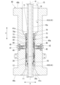
- FIG. 1 is a vertical cross-sectional view showing a schematic configuration of a packer system.
- FIG. 2 is a vertical cross-sectional view showing the schematic configuration of the packer system from another direction.
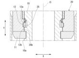
- FIG. 2 is an enlarged view of a main portion showing the connection between the drill pipe and the packer assembly.
- FIG. 2 is an enlarged longitudinal sectional view of the main parts of the packer housing and the packer assembly.
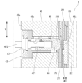
- FIG. 13 is a longitudinal cross-sectional view showing the configuration of the packer holding mechanism, in a holding state.
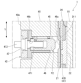
- FIG. 13 is a longitudinal cross-sectional view showing the configuration of the packer holding mechanism, illustrating a state before holding.
- packer system 1 The packer system for drill pipe of this embodiment shown in Figures 1 and 2 (hereinafter simply referred to as packer system 1) is designed so that the packer assembly 20 can be recovered and replaced together with the drill pipe 10.
- the drill pipe 10, packer assembly 20, and packer housing 40 are each arranged coaxially in the up-down direction Y (vertical direction) underwater, and the central axis at this time is the pipe axis O.
- the direction perpendicular to the pipe axis O is the radial direction
- the direction of rotation around the pipe axis O as viewed from the pipe axis O direction is the circumferential direction.
- the packer system 1 is a system that is sealed, rotatable, and slidable with the drill pipe 10 inserted through it.
- the packer system 1 includes a packer assembly 20 having a packer body 30 through which the drill pipe 10 is inserted and which is held in close contact with the outer peripheral surface 10a of the drill pipe 10, a packer housing 40 through which the drill pipe 10 and the packer assembly 20 are inserted at a fixed position and which supports them liquid-tight inside, and a packer drive unit 50 that is provided on the outside of the packer housing 40 and applies a drive pressure to the packer body 30.
- the drill pipe 10 is arranged so that it can be inserted through the packer assembly 20.
- the packer body 30 contacts the outer peripheral surface 10a of the drill pipe 10 and holds the drill pipe 10 so that it can move in the vertical direction Y.
- the drill pipes 10 are hollow steel pipes, each 9 m long and threaded at both ends, and are used to drill holes in the seabed by connecting multiple pipes together and lowering them.
- a drilling blade (not shown), for example, is attached to the lower end of the drill pipe 10, which is located at the lowest end.
- the seabed can be excavated by rotating the drilling blade.
- the drill pipe 10 and the drilling blade at the lower end of the drill pipe are rotated by the driving force of the top drive (not shown) on the ship, and the seabed is excavated by the rotating drilling blade, and the excavated soil is mixed with the supplied seawater.
- the excavated soil generated by the drilling blade is then discharged into the sea together with the mixed mud water.
- a flange-shaped support stopper 11 that protrudes radially outward is fixed integrally to a portion of the outer circumferential surface 10a of the drill pipe 10.
- the support stopper 11 supports the packer assembly 20 through which the drill pipe 10 is inserted from below.
- the packer assembly 20 can be stopped by the support stopper 11 when it is lowered along the drill pipe 10.
- the packer assembly 20 can be positioned at a predetermined height on the drill pipe 10.
- the packer assembly 20 can be prevented from falling below a predetermined position on the drill pipe 10.
- An engagement ring 12 extending over the entire circumference is provided above the support stopper 11 on the outer circumferential surface 10a of the drill pipe 10.
- the engagement ring 12 is fixed to the drill pipe 10 in a state in which it can be contracted, and in an expanded state, it protrudes radially outward from the outer circumferential surface 10a.
- the engagement ring 12 is contracted to a position where it is flush with the outer circumferential surface 10a of the drill pipe 10, or to a position where it is more inward than the outer circumferential surface 10a.
- the engagement ring 12 has an upper surface 12a that is a downwardly inclined surface, and a lower surface 12b that is a vertical surface that is horizontally perpendicular to the pipe axis O.
- the lower surface 12b of the engagement ring 12 may also be formed with an upwardly inclined surface, similar to the upper surface 12a. Providing an upwardly inclined surface on the lower surface 12b in this manner is also effective when recovering the packer assembly 20 on board a ship.
- the riser pipe 15 shown by the two-dot chain line is coaxially connected to each of the upper end 40b and the lower end 40c of the packer housing 40.
- the two-dot chain line shown in FIG. 1 indicates the position of the inner peripheral surface of the riser pipe 15.
- the packer housing 40 is formed in a cylindrical shape having an insertion hole 41 along the pipe axis O, and is provided with a pair of packer driving parts 50 (see Fig. 1) on the outer circumferential surface 40a.
- the insertion hole 41 is composed of an upper insertion hole 41A and a lower insertion hole 41B that communicates with the upper insertion hole 41A.
- the packer housing 40 also includes a packer holding mechanism 42 for holding the packer assembly 20 inserted into the insertion hole 41 at a predetermined position in the vertical direction Y.
- the upper insertion hole 41A extends from the upper end 40b of the packer housing 40 to approximately the middle in the height direction (vertical direction Y).
- the lower insertion hole 41B extends from the lower end of the upper insertion hole 41A to the lower end 40c of the packer housing 40.
- the inner diameter of the upper insertion hole 41A is the same as the inner diameter of the riser pipe and is larger than the inner diameter of the lower insertion hole 41B.
- the lower end of the upper insertion hole 41A is formed with a tapered surface 41a whose diameter dimension gradually decreases toward the upper end of the lower insertion hole 41B.
- the packer housing 40 is also provided with a seawater inlet passage 48 (see FIG. 1) that connects from the outer peripheral surface 40a to a position approximately in the middle of the upper insertion hole 41A in the vertical direction Y.
- the lower end of the lower insertion hole 41B is formed with a tapered surface 41c whose diameter dimension gradually increases toward the lower end 40c of the packer housing 40.
- the lower end opening of the lower insertion hole 41B has the same diameter as the inner diameter of the riser pipe 15.
- the packer housing 40 is provided with a second flow path 44 that connects a pipe 54 connected to the outlet 522 of the fluid V of the packer drive unit 50 and a first flow path 23 (described later) provided in the packer assembly 20. That is, the flow path opening 44a on the outer circumferential surface 40a side of the second flow path 44 is connected to the pipe 54.
- the flow path opening 44b on the lower insertion hole 41B side is connected to the space of the lower insertion hole 41B and is connected to the first flow path 23 of the packer assembly 20 held at a predetermined position of the packer housing 40.
- the second flow path 44 is arranged to extend in the radial direction and is connected to a predetermined position at approximately the middle of the packer housing 40 in the vertical direction Y.
- a plurality of second flow paths 44 are provided at intervals in the circumferential direction.
- examples of the fluid V that flows through the packer drive unit 50, the second flow path 44, and the first flow path described below include oil, seawater, etc.
- the packer housing 40 is formed with a through-hole 45 that penetrates the cylindrical wall in the thickness direction from the outer peripheral surface 40a toward the lower insertion hole 41B.
- a plurality of through-holes 45 are provided at intervals in the circumferential direction.
- the packer holding mechanism 42 is disposed in the through-hole 45.
- a locking pin 46 of the packer holding mechanism 42 is provided at the opening on the inner peripheral side of the through-hole 45 so as to be able to protrude from the inner surface of the lower insertion hole 41B.
- the locking pin 46 of the packer holding mechanism 42 can hold the packer assembly 20 in the packer housing 40 by engaging with an outer peripheral groove 211 provided in an outer cylinder 21 of the packer assembly 20 (described later).
- the packer holding mechanism 42 includes a locking pin 46 that can protrude radially inward, and a rotary screw drive device 47 that moves the locking pin 46 in and out radially.
- the locking pin 46 is disposed on the radially inner side of the lower insertion hole 41B, and the rotary screw drive device 47 is disposed on the radially outer side.
- the locking pin 46 has a locking portion 46a formed on its inner periphery and a female thread 46b formed on its outer periphery. The male thread portion 471 of the rotary screw drive device 47 is screwed into the female thread 46b.
- the rotating screw drive device 47 includes the male threaded portion 471 described above and a screw operating portion 472 that rotates the male threaded portion 471.
- the screw operating portion 472 is exposed to the outer circumferential surface 40a of the packer housing 40, and is provided so that it can be screwed and rotated from an external ROV or the like.
- the screw operating portion 472 is screwed, the male threaded portion 471 rotates, and the locking portion 46a of the locking pin 46 that is screwed into the male threaded portion 471 can be protruded to the inside of the lower insertion hole 41B.
- a tapered support surface 43 is formed on the lower part of the inner peripheral surface 40d of the packer housing 40, which supports from below the downward tapered surface 24 formed on the packer assembly 20 described later.
- the tapered support surface 43 has an upward tapered surface.
- the packer drive unit 50 includes a rotary screw drive piston 51 and a fluid chamber 52.
- the rotary screw drive piston 51 is provided on the top of the fluid chamber 52.
- the screw operation part 511 of the rotary screw drive piston 51 is attached facing upward outside the fluid chamber 52 and exposed to the sea.
- the piston 512 of the rotary screw drive piston 51 faces the fluid chamber 52.
- the rotary screw drive piston 51 is driven by a screw operation from an ROV connected externally to pressurize the fluid chamber 52.
- the fluid chamber 52 contains the fluid V, and the fluid V inside is pressurized by driving the rotary screw drive piston 51.
- An outlet 522 is provided in a bottom wall 521 of the fluid chamber 52.
- a pipe 54 is connected to the outlet 522.
- One end of the pipe 54 is connected to the outlet 522, and the other end is connected to a second flow path 44 of the packer housing 40, which will be described later.
- the fluid V is pressurized by driving the rotary screw drive piston 51, and the packer body 30 presses against the drill pipe 10 with a predetermined pressing force, thereby maintaining the sealing ability of the packer body 30.
- the packer assembly 20 is composed of an outer cylinder 21 and an inner cylinder 22.
- a pair of grooves 221 extending in the circumferential direction is provided on the inner surface of the inner cylinder 22 at positions spaced apart in the up-down direction Y.
- a ring-shaped packer body 30 extending in the circumferential direction is provided in each of the pair of grooves 221.
- the outer peripheral surface 21a of the outer tube 21 is formed with an outer peripheral groove 211 that extends continuously in the circumferential direction.
- the locking pin 46 of the packer holding mechanism 42 shown in FIG. 5 slides radially inward in the outer peripheral groove 211 and is locked in a state where it protrudes from the inner surface of the lower insertion hole 41B.
- the lower part of the outer peripheral surface 21a of the outer tube 21 is provided with a downward tapered surface 24.
- the downward tapered surface 24 is placed in contact from above against a tapered receiving surface 43 formed on the inner peripheral surface 40d of the packer housing 40, and the position of the packer assembly 20 in the up-down direction Y is determined at a predetermined position of the packer housing 40.
- the lower inner surface 20b of the packer assembly 20 is provided with an engagement ring receiving portion 25 that engages with the engagement ring 12 provided on the outer peripheral surface 10a of the drill pipe 10.
- the engagement ring receiving portion 25 extends around the entire circumferential direction on the lower inner surface 20b of the packer assembly 20.
- the engagement ring receiving portion 25 engages with the engagement ring 12. This allows the packer assembly 20 to be fixed to the drill pipe 10.
- a centralizer 70 is provided at the upper end of the packer assembly 20.
- the centralizer 70 aligns the center axis (pipe axis O) of the drill pipe 10 so that it is coaxial with the center of the packer housing 40 and the packer assembly 20, and has a function of preventing it from falling.
- the centralizer 70 may be omitted.
- the centralizer 70 is cylindrical with a pipe hole 71 in the center with an inner diameter equal to the outer diameter of the drill pipe 10.
- the outer peripheral surface 70a of the centralizer 70 is formed with a downward step 72 that engages from above with the corner (step 41b) between the tapered surface 41a of the upper insertion hole 41A and the lower insertion hole 41B of the packer housing 40.
- the downward step 72 of the centralizer 70 can be engaged with the step 41b of the packer housing 40.
- the centralizer 70 is coaxial with the packer assembly 20, and the lower surface 70b of the centralizer 70 is fixed to the upper surface of the packer assembly 20 with bolts 73.
- the drill pipe 10 passing through the centralizer 70 is arranged coaxially with the packer assembly 20 by the centralizer 70. Therefore, uneven wear of the packer body 30 that seals the drill pipe 10 and accelerated wear can be suppressed, as occurs when the drill pipe 10 is eccentric with respect to the packer assembly 20.
- the packer bodies 30 are provided in two tiers, upper and lower, spaced apart in the up-down direction Y of the inner cylinder 22, and each tier is provided around the entire circumference in the circumferential direction.
- the packer bodies 30 are provided in a state in which they cannot rotate around the pipe axis O relative to the inner cylinder 22, and are provided movable in a radial direction perpendicular to the pipe axis O.
- the packer bodies 30 also hold the outer circumferential surface 10a of the drill pipe 10 so as to be movable in the up-down direction Y.
- the packer body 30 is formed in a trapezoidal shape in which the dimension in the vertical direction Y gradually decreases from the contact surface 30a located on the radial inside and in contact with the outer circumferential surface 10a of the drill pipe 10 toward the outer circumferential surface 30b located on the radial outside.
- a packer piston 26, which will be described later, is fixed to at least one of the upper inclined surface 30c and the lower inclined surface 30d of the packer body 30.
- the packer assembly 20 includes a packer piston 26 that is moved up and down by the fluid V.
- the packer piston 26 is configured to displace the packer body 30 inward in the radial direction perpendicular to the pipe axis direction of the drill pipe 10 by vertical movement.
- the packer piston 26 is provided in the inner tube 22 and arranged so that the extension direction is along the pipe axis O.
- a pressing end 26a at one end of the packer piston 26 abuts against at least one of the upper inclined surface 30c and the lower inclined surface 30d of the packer body 30, and a base end 26b at the other end is connected to a first flow path 23 described later.
- the pressing end 26a is inclined at the same inclination angle as the inclination of the upper inclined surface 30c and the lower inclined surface 30d of the packer body 30.
- the packer piston 26 is expanded by applying the pressure of the fluid V, and the pressing end 26a presses the packer body 30 in the vertical direction Y. This causes the packer body 30 to be pushed inward in the radial direction.
- the packer assembly 20 is provided with a first flow path 23 that allows the fluid V from the packer drive unit 50 to flow and is capable of communicating with the second flow path 44 of the packer housing 40.
- the first flow path 23 has a horizontal flow path 23A that extends horizontally (perpendicular to the pipe axis O) from the outer circumferential surface of the outer tube 21 into the interior of the inner tube 22, and a vertical flow path 23B that branches off from the end of the horizontal flow path 23A on the inner tube 22 side in the vertical direction Y and extends in a direction parallel to the pipe axis O.
- the horizontal flow path 23A is provided so that an outer flow path 231 provided in the outer tube 21 and an inner flow path 232 provided in the inner tube 22 are connected to each other.
- One end of the vertical flow path 23B is connected to the inner flow path 232, and the other end is connected to the base end 26b of the packer piston 26.
- the inlet 23a opening on the outer circumferential surface 21a of the outer cylinder 21 of the first flow passage 23 can be connected to the inner opening (flow passage port 44b) of the second flow passage 44 when the packer assembly 20 is positioned at a predetermined rotational position relative to the packer housing 40.
- Fluid V flowing in from the packer drive unit 50 through the piping 54 (see FIG. 1) flows into the first flow passage 23 via the second flow passage 44, and extends the packer piston 26, transmitting the force to the packer body 30 and applying a pressing force.
- the support state between the packer casing 40 and the packer assembly 20 is released. That is, as shown in Fig. 6, the locking pin 46 of the packer holding mechanism 42 of the packer casing 40 is released from the outer circumferential groove 211 of the packer assembly 20.
- the packer assembly 20 is held by the drill pipe 10 equipped with the support stopper 11. That is, when the packer assembly 20 is lowered along the drill pipe 10, it can be locked on the support stopper 11, and the state of being held by the support stopper 11 is maintained.
- the packer assembly 20 is pulled up onto a ship (not shown) together with the drill pipe 10 and detached from the packer housing 40.
- the packer body 30 of the packer assembly 20 that was pulled up from the sea is then replaced.
- the packer assembly 20 with the replaced packer body 30 is lowered together with the drill pipe 10, and the packer assembly 20 is held in the packer housing 40. This completes the replacement work of the packer body 30.
- the packer assembly 20 is rotatably supported by the packer housing 40, and the drill pipe 10 inserted inside the packer assembly 20 is held liquid-tight by the pressing force of the packer body 30, so that water can be stopped from spraying from above and below between the riser pipe 15 connected below the packer housing 40 and the drill pipe 10, and the packer body 30 can also dam seawater when it flows from the drill pipe 10 to the annulus.
- the fluid V of the packer drive unit 50 (see FIG. 1) provided on the outside of the packer housing 40 constantly exerts a pressing force on the packer body 30 through the first flow path 23 and the second flow path 44, so that the sealing ability of the packer body 30 can be maintained.
- the packer assembly 20 equipped with the packer body 30 is detachably and rotatably attached to the packer housing 40. Therefore, when the packer body 30 wears out and needs to be replaced, the packer assembly 20 can be detached from the packer housing 40, and the packer assembly 20 attached to the drill pipe 10 can be pulled up and recovered together with the drill pipe 10, and the packer body 30 can be replaced.
- the packer assembly 20 is composed of an outer cylinder 21 and an inner cylinder 22.
- a pair of grooves 221 extending circumferentially are formed on the inner surface of the inner cylinder 22 at positions spaced apart in the up-down direction Y.
- a packer body 30 is provided in each of the pair of grooves 221.
- the packer body 30 is housed in a pair of grooves 221 provided in the inner cylinder 22 of the packer assembly 20, providing a double sealing function in the vertical direction Y. This can reliably prevent seawater from spraying out from above and below the packer assembly 20.
- the packer body 30 can reliably block the seawater.
- a downward tapered surface 24 is provided on the lower outer peripheral surface of the packer assembly 20.
- a tapered support surface 43 is formed to position the packer assembly 20 in a fixed position while supporting the downward tapered surface 24 from below.
- the packer housing 40 is provided with a locking pin 46 that can protrude inward.
- a peripheral groove 211 that extends continuously in the circumferential direction is formed on the outer peripheral surface of the outer tube 21, and when the locking pin 46 is protruding, it is locked into the peripheral groove 211 of the outer tube 21, restricting the movement of the outer tube 21 in the up-down direction Y and allowing it to rotate in the circumferential direction.
- the inner tube 22 of the packer assembly 20 can apply a pressing force to the packer body 30, providing a sealing function for the drill pipe 10, and the outer tube 21 can provide the function of holding it in the packer housing 40. Because the outer tube 21 and inner tube 22 are provided separately in this way, the outer tube 21 and inner tube 22 can independently bear the forces acting on each, realizing an effective configuration that does not affect the functions of each.
- the packer assembly 20 is provided with an engagement ring receiving portion 25 that rotatably engages with the engagement ring 12 provided on the outer circumferential surface 10 a of the drill pipe 10 .
- the drill pipe 10 can be pushed downward with a predetermined force to disengage the engagement ring 12 from the engagement ring receiving portion 25, and the drill pipe 10, which has been separated from the packer assembly 20, can be lowered or pulled up alone, with the packer assembly 20 remaining in the packer housing 40.
- the packer assembly 20 is equipped with a packer piston 26 that moves up and down due to the fluid V.
- the packer piston 26 moves up and down due to the inflow and outflow of the fluid V, and is displaced in a radial direction perpendicular to the pipe axis direction of the drill pipe 10 relative to the packer body 30.
- the packer piston 26 can be moved up and down by the inflow and outflow of the fluid V, displacing the packer body 30 in a radial direction perpendicular to the pipe axial direction of the drill pipe 10, thereby applying a pressing force to the packer body 30.
- a pressing force can be easily applied to the packer body 30 using the fluid V.
- the packer drive unit 50 is composed of a rotary screw drive piston 51 and a fluid chamber 52, and is pressurized by external screw operation. The pressure generated by this pressurization presses the packer body 30 against the drill pipe 10 with a predetermined pressing force, thereby maintaining the sealing ability of the packer body 30.
- the packer drive unit 50 which is equipped with a rotary screw drive piston 51 and a fluid chamber 52, can apply pressure to the fluid V by a mechanical drive method rather than an electrical drive.
- the pressure of the fluid V can then be transmitted to the packer body 30 of the packer assembly 20, thereby maintaining the sealing ability of the packer body 30.
- the packer assembly 20 is composed of an outer cylinder 21 and an inner cylinder 22, but this is not limited to this, and the outer cylinder 21 and the inner cylinder 22 may be configured to be integral with each other.
- the packer drive unit 50 is used to apply a pressurizing force to the fluid V by a mechanical drive method as a drive method for applying a pressing force to the packer body 30, but this is not limited to this.
- a configuration in which a hydraulic unit is directly connected to the packer body 30, or a method in which a pressing force is applied using a spring force or an accumulator may be used.
- the packer assembly 20 is configured with an engagement ring receiving portion 25 that rotatably engages with the engagement ring 12 provided on the outer circumferential surface 10a of the drill pipe 10, but this is not limited to this and other engagement methods can also be used.
- the present invention can be used in a packer replacement method using a packer system for drill pipes and a packer system for offshore drilling.
- Packer system (packer system for drill pipe) REFERENCE SIGNS LIST 10 drill pipe 10a outer circumferential surface 11 support stopper 12 engagement ring 20 packer assembly 21 outer cylinder 211 outer circumferential groove 22 inner cylinder 221 concave groove 23 first flow passage 24 downward tapered surface 25 engagement ring receiving portion 26 packer piston 30 packer body 40 packer housing 41 insertion hole 42 packer holding mechanism 43 tapered receiving surface 44 second flow passage 46 locking pin 50 packer drive portion 51 rotary screw drive piston 52 fluid chamber 70 centralizer O pipe axis V fluid
Landscapes
- Life Sciences & Earth Sciences (AREA)
- Engineering & Computer Science (AREA)
- Geology (AREA)
- Mining & Mineral Resources (AREA)
- Physics & Mathematics (AREA)
- Environmental & Geological Engineering (AREA)
- Fluid Mechanics (AREA)
- General Life Sciences & Earth Sciences (AREA)
- Geochemistry & Mineralogy (AREA)
- Earth Drilling (AREA)
Priority Applications (3)
| Application Number | Priority Date | Filing Date | Title |
|---|---|---|---|
| JP2024575902A JPWO2024166198A1 (cg-RX-API-DMAC7.html) | 2023-02-07 | 2023-02-07 | |
| AU2023429356A AU2023429356A1 (en) | 2023-02-07 | 2023-02-07 | Packer system for drill pipe and packer replacement method using packer system for seabed drilling |
| PCT/JP2023/003943 WO2024166198A1 (ja) | 2023-02-07 | 2023-02-07 | ドリルパイプ用パッカーシステム、および海底掘削用パッカーシステムを使用したパッカー交換方法 |
Applications Claiming Priority (1)
| Application Number | Priority Date | Filing Date | Title |
|---|---|---|---|
| PCT/JP2023/003943 WO2024166198A1 (ja) | 2023-02-07 | 2023-02-07 | ドリルパイプ用パッカーシステム、および海底掘削用パッカーシステムを使用したパッカー交換方法 |
Publications (1)
| Publication Number | Publication Date |
|---|---|
| WO2024166198A1 true WO2024166198A1 (ja) | 2024-08-15 |
Family
ID=92262143
Family Applications (1)
| Application Number | Title | Priority Date | Filing Date |
|---|---|---|---|
| PCT/JP2023/003943 Ceased WO2024166198A1 (ja) | 2023-02-07 | 2023-02-07 | ドリルパイプ用パッカーシステム、および海底掘削用パッカーシステムを使用したパッカー交換方法 |
Country Status (3)
| Country | Link |
|---|---|
| JP (1) | JPWO2024166198A1 (cg-RX-API-DMAC7.html) |
| AU (1) | AU2023429356A1 (cg-RX-API-DMAC7.html) |
| WO (1) | WO2024166198A1 (cg-RX-API-DMAC7.html) |
Citations (7)
| Publication number | Priority date | Publication date | Assignee | Title |
|---|---|---|---|---|
| JPS57501485A (cg-RX-API-DMAC7.html) * | 1980-02-29 | 1982-08-19 | ||
| US4345649A (en) * | 1980-09-05 | 1982-08-24 | Hughes Tool Company | Well packer |
| JPS63272894A (ja) * | 1987-04-30 | 1988-11-10 | カメロン・アイアン・ワークス・ユーエスエイ・インコーポレーテッド | 管状パッカ |
| JPH03233092A (ja) * | 1990-02-06 | 1991-10-17 | Kanto Tennen Gas Kaihatsu Kk | リューブリケータ |
| US20050211446A1 (en) * | 2004-03-23 | 2005-09-29 | Smith International, Inc. | System and method for installing a liner in a borehole |
| US20080308282A1 (en) * | 2007-06-13 | 2008-12-18 | Halliburton Energy Services, Inc. | Hydraulic coiled tubing retrievable bridge plug |
| JP2009097155A (ja) * | 2007-10-12 | 2009-05-07 | Raito Kogyo Co Ltd | 口元止水装置、口元止水装置用弾性体及び口元止水装置用弾性体の製造方法 |
-
2023
- 2023-02-07 JP JP2024575902A patent/JPWO2024166198A1/ja active Pending
- 2023-02-07 AU AU2023429356A patent/AU2023429356A1/en active Pending
- 2023-02-07 WO PCT/JP2023/003943 patent/WO2024166198A1/ja not_active Ceased
Patent Citations (7)
| Publication number | Priority date | Publication date | Assignee | Title |
|---|---|---|---|---|
| JPS57501485A (cg-RX-API-DMAC7.html) * | 1980-02-29 | 1982-08-19 | ||
| US4345649A (en) * | 1980-09-05 | 1982-08-24 | Hughes Tool Company | Well packer |
| JPS63272894A (ja) * | 1987-04-30 | 1988-11-10 | カメロン・アイアン・ワークス・ユーエスエイ・インコーポレーテッド | 管状パッカ |
| JPH03233092A (ja) * | 1990-02-06 | 1991-10-17 | Kanto Tennen Gas Kaihatsu Kk | リューブリケータ |
| US20050211446A1 (en) * | 2004-03-23 | 2005-09-29 | Smith International, Inc. | System and method for installing a liner in a borehole |
| US20080308282A1 (en) * | 2007-06-13 | 2008-12-18 | Halliburton Energy Services, Inc. | Hydraulic coiled tubing retrievable bridge plug |
| JP2009097155A (ja) * | 2007-10-12 | 2009-05-07 | Raito Kogyo Co Ltd | 口元止水装置、口元止水装置用弾性体及び口元止水装置用弾性体の製造方法 |
Also Published As
| Publication number | Publication date |
|---|---|
| JPWO2024166198A1 (cg-RX-API-DMAC7.html) | 2024-08-15 |
| AU2023429356A1 (en) | 2025-08-21 |
Similar Documents
| Publication | Publication Date | Title |
|---|---|---|
| US9605504B2 (en) | Sealing assembly | |
| US4712620A (en) | Upper marine riser package | |
| US5022472A (en) | Hydraulic clamp for rotary drilling head | |
| US5002131A (en) | Casing tensioning mechanism for a casing hanger | |
| US5372201A (en) | Annulus pressure actuated casing hanger running tool | |
| NO314511B1 (no) | Apparat og fremgangsmåte for ekspandering av en utbedringsfôring | |
| US20070267197A1 (en) | Rapid Makeup Drilling Riser | |
| CA3091991A1 (en) | Improved rotating control device for jackup rigs | |
| NO339578B1 (no) | Fremgangsmåte og system for å føre borevæske ved bruk av en konstruksjon som flyter i en overflate av et hav | |
| EP2529077B1 (en) | Underwater stuffing box and a method for running a drill string through the stuffing box | |
| AU2011203299A1 (en) | Made-up flange locking cap | |
| NO20110972A1 (no) | Lasende, undersjoisk forbindelsesledd | |
| US12473792B2 (en) | Systems and methods for cementing casing and sealing a hanger in a wellhead housing | |
| US9677374B2 (en) | Hydraulic tool | |
| NO332617B1 (no) | Undersjøisk brønnhodeutstyr | |
| CN113323606B (zh) | 适用于水下井口及表层导管打桩施工连接装置及装配方法 | |
| NO20161044A1 (no) | Pakkboks og fremgangsmåte ved installasjon eller trekking av et pakningselement i, henholdsvis fra en pakkboks for anvendelse ved petroleumsboring | |
| US20160186520A1 (en) | Landing system | |
| NO335983B1 (no) | Modulær opphentbar pakning og fremgangsmåte for dette. | |
| US4825948A (en) | Remotely variable multiple bore ram system and method | |
| US10378300B2 (en) | System and method for landing equipment with retractable shoulder assembly | |
| AU2004260146B2 (en) | Subsea tubing hanger lockdown device | |
| EP0378040B1 (en) | Casing hanger running and retrieval tools | |
| CA2533679A1 (en) | Displacement annular swivel | |
| US12180793B2 (en) | Open water recovery system and method |
Legal Events
| Date | Code | Title | Description |
|---|---|---|---|
| 121 | Ep: the epo has been informed by wipo that ep was designated in this application |
Ref document number: 23921034 Country of ref document: EP Kind code of ref document: A1 |
|
| ENP | Entry into the national phase |
Ref document number: 2024575902 Country of ref document: JP Kind code of ref document: A |
|
| WWE | Wipo information: entry into national phase |
Ref document number: AU2023429356 Country of ref document: AU Ref document number: 2024575902 Country of ref document: JP |
|
| ENP | Entry into the national phase |
Ref document number: 2023429356 Country of ref document: AU Date of ref document: 20230207 Kind code of ref document: A |
|
| NENP | Non-entry into the national phase |
Ref country code: DE |
|
| 122 | Ep: pct application non-entry in european phase |
Ref document number: 23921034 Country of ref document: EP Kind code of ref document: A1 |