WO2024161927A1 - 音響機器 - Google Patents
音響機器 Download PDFInfo
- Publication number
- WO2024161927A1 WO2024161927A1 PCT/JP2024/000358 JP2024000358W WO2024161927A1 WO 2024161927 A1 WO2024161927 A1 WO 2024161927A1 JP 2024000358 W JP2024000358 W JP 2024000358W WO 2024161927 A1 WO2024161927 A1 WO 2024161927A1
- Authority
- WO
- WIPO (PCT)
- Prior art keywords
- housing
- elastic member
- vibration
- wearer
- electroacoustic transducer
- Prior art date
- Legal status (The legal status is an assumption and is not a legal conclusion. Google has not performed a legal analysis and makes no representation as to the accuracy of the status listed.)
- Ceased
Links
Images




Classifications
-
- H—ELECTRICITY
- H04—ELECTRIC COMMUNICATION TECHNIQUE
- H04R—LOUDSPEAKERS, MICROPHONES, GRAMOPHONE PICK-UPS OR LIKE ACOUSTIC ELECTROMECHANICAL TRANSDUCERS; ELECTRIC HEARING AIDS; PUBLIC ADDRESS SYSTEMS
- H04R5/00—Stereophonic arrangements
- H04R5/033—Headphones for stereophonic communication
-
- H—ELECTRICITY
- H04—ELECTRIC COMMUNICATION TECHNIQUE
- H04R—LOUDSPEAKERS, MICROPHONES, GRAMOPHONE PICK-UPS OR LIKE ACOUSTIC ELECTROMECHANICAL TRANSDUCERS; ELECTRIC HEARING AIDS; PUBLIC ADDRESS SYSTEMS
- H04R11/00—Transducers of moving-armature or moving-core type
- H04R11/02—Loudspeakers
-
- H—ELECTRICITY
- H04—ELECTRIC COMMUNICATION TECHNIQUE
- H04R—LOUDSPEAKERS, MICROPHONES, GRAMOPHONE PICK-UPS OR LIKE ACOUSTIC ELECTROMECHANICAL TRANSDUCERS; ELECTRIC HEARING AIDS; PUBLIC ADDRESS SYSTEMS
- H04R2460/00—Details of hearing devices, i.e. of ear- or headphones covered by H04R1/10 or H04R5/033 but not provided for in any of their subgroups, or of hearing aids covered by H04R25/00 but not provided for in any of its subgroups
- H04R2460/13—Hearing devices using bone conduction transducers
Definitions
- the present invention relates to an acoustic device that uses bone conduction.
- cartilage conduction vibration source devices for mobile phones and the like that acoustically process audio signals for cartilage conduction vibration and output the processed signals as drive signals to a cartilage conduction vibration source (see, for example, Patent Document 1).
- a stereo earphone has been disclosed that has a cartilage conduction section and a branch section that is connected at one end to the cartilage conduction section and serves as a vibration source (see, for example, Patent Document 2).
- Sound output devices that use bone conduction have a vibration unit that vibrates in response to an audio signal.
- the sound output device may not fit the wearer's head, and the vibrations from the vibration unit may not be transmitted to the bone.
- the volume of sound heard by the wearer may be significantly reduced.
- none of the documents disclose any technology for ensuring high-quality sound by fitting the head to the wearer's head regardless of individual differences in sound output devices that use bone conduction.
- the objective of the present invention is to provide audio equipment that can ensure high-quality sound by fitting to the head regardless of individual differences.
- the acoustic device of the present invention comprises an electroacoustic transducer that generates vibrations that are transmitted to the wearer's bones, a housing that houses the electroacoustic transducer, and an elastic member that is disposed at least on the outer surface of the housing that faces the wearer when the device is worn.
- the present invention provides audio equipment that can ensure high-quality sound by fitting to the head regardless of individual differences.
- FIG. 1 is a schematic perspective view showing an embodiment of a headphone as an example of an audio device according to the present invention.
- FIG. 2 is a schematic partially enlarged perspective view showing the state of a housing of the headphones. 4 is a graph showing frequency characteristics of the above headphones and a frequency characteristic of a first related art.
- 1A is a perspective view of a headphone unit according to a first embodiment of the present invention, and FIG. 1B is a perspective view of the same as seen from the rear side.
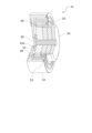
- FIG. 2 is an exploded perspective view of the headphone unit.
- FIG. 2 is a vertical cross-sectional view of the headphone unit.
- 3 is a half-sectional view showing a vibrating portion of the headphone unit.
- FIG. 11 is a half-side cross-sectional view showing a second embodiment of a headphone unit according to the present invention.
- FIG. 11 is a longitudinal sectional view of a headphone unit according to a second related art.
- FIG. 11 is a schematic perspective view showing a second embodiment of an acoustic device according to the present invention.
- the axial direction of the electro-acoustic transducer 1 will be referred to as the y direction, and the directions perpendicular to the y direction will be referred to as the x direction and z direction.
- the surface facing the +z direction will be referred to as the top surface, and the surface facing the -z direction will be referred to as the bottom surface.
- the surface facing the -y direction will be referred to as the front surface, and the surface facing the +y direction will be referred to as the back surface.
- the headphone 1000 as an example of an acoustic device will be described with reference to Fig. 1.
- the headphone 1000 mainly includes a pair of electroacoustic transducers 1, a pair of housings 2, and a headband 3.
- Each of the pair of housings 2 is substantially triangular prism-shaped and incorporates the electroacoustic transducer 1 therein.
- the shape of the housing 2 is arbitrary, and may be substantially rectangular parallelepiped.
- the headband 3 is a substantially U-shaped member. Both ends of the headband 3 are curved in a direction substantially perpendicular to the U-shaped portion, so that the headband 3 can be hung on the wearer's ears when worn.
- the housings 2 are connected to both ends of the headband 3. That is, the electroacoustic transducer 1 is held via the housings 2 at both ends of the headband 3.
- the headband 3 sandwiches the wearer's head when worn, and the outer surface 2a of the housing 2 facing the wearer is pressed against the ears by the elastic force of the headband 3.
- the headband 3 is an example of a housing holding portion in the claims.
- ear cartilage also called tragus cartilage or auricular cartilage
- the technical scope of the present invention is not limited to this and includes headphones and electroacoustic transducers that transmit vibrations to any bone including cartilage tissue other than ear cartilage and hard bone tissue such as the skull.
- bone in the claims is a concept that includes either or both of cartilage tissue and hard bone tissue.
- an elastic member 2b is provided on the outer surface 2a of the housing 2 that faces the wearer when the housing 2 is worn.
- the outer surfaces 2a are the surfaces of the pair of housings 2 that are substantially opposed to each other.
- the elastic member 2b is interposed between the housing 2 and the wearer's head when the device is worn, and is pressed against the head. More specifically, the elastic member 2b is a member that is pressed against the ear cartilage or skull. The elastic member 2b fits closely to the unevenness of the wearer's body shape without any gaps.
- the elastic member 2b is disposed over the entire outer surface 2a, but it may be disposed over at least a part of the outer surface 2a, or may extend from the outer surface 2a. Furthermore, in the figure, the elastic member 2b has a roughly triangular shape similar to the outer surface 2a, but the shape is arbitrary. Note that the elastic member 2b may be disposed on a surface other than the outer surface 2a, and may be disposed, for example, in a ring shape along the outer periphery of the housing 2, or may be disposed over the entire periphery. Note that if appropriate controls are disposed on the housing 2, it is preferable that the elastic member 2b be disposed to avoid the controls.
- the elastic member 2b is detachably arranged on the housing 2.
- the elastic member 2b is attached to the housing 2 with, for example, a weak double-sided tape, so that it can be detached.
- the elastic member may be in a bag shape and cover the housing 2.
- the elastic member may be in a ring shape and cover the outer periphery of the housing 2. In this case, the elastic member adheres to the outer periphery of the housing 2 by its own elastic force.
- the housing 2 may have a structure that fits the elastic member. In this case, specifically, for example, the housing 2 and a soft material are integrally molded by insert molding or the like, and the elastic member fits to this soft material. Furthermore, the elastic member 2b and the housing 2 may have hook-and-loop fasteners that fit each other.
- the wearer can easily replace the elastic member 2b. In other words, even if the elastic member 2b deteriorates over time, it can be easily replaced.
- the wearer can also select from multiple types of elastic members according to their preference for usability and sound quality.
- the elastic member 2b may be, for example, a sponge, urethane foam, rubber sponge, or other suitable material having elasticity.
- the elastic member 2b may be a material with a relatively low coefficient of resilience, such as a so-called low-resilience sponge, for example, low-resilience urethane foam.
- the elastic member 2b is not limited to a material having elasticity due to the properties of the material itself, but may be a material that exhibits elasticity due to its mechanical shape. In other words, the elastic member 2b may be a material such as a coil spring, leaf spring, or spiral spring.
- the elastic member 2b may be a single member, or may be composed of multiple members.
- the elastic member 2b feels softer than the housing 2. Therefore, a configuration in which the elastic member 2b abuts against the head improves the fit for the wearer. Also, when worn, the elastic member 2b is pressed and elastically deformed to fit closely to the wearer's body shape, in this case the unevenness of the head, without any gaps, improving the fit to the head. Furthermore, a configuration in which the housing 2 fits closely can prevent the headphones 1000 from slipping off the head.
- ear cartilage has a three-dimensional shape compared to the skull, which is relatively flat. Furthermore, the shape of ear cartilage varies greatly from person to person. Therefore, in a configuration in which the relatively hard housing 2 is pressed directly against the ear cartilage, there is a risk of concentrated pressure being applied to the abutting part.
- a configuration including the elastic member 2b allows the housing 2 to fit evenly to ear cartilage, which has a three-dimensional shape that varies greatly from person to person. Furthermore, this configuration reduces the variation in vibration transmission efficiency between individuals in cartilage conduction headphones that transmit vibrations to the ear cartilage.
- the elastic member 2b is thin enough to transmit sound sufficiently to the wearer, and thick enough to fit closely to the irregularities of the body shape without any gaps.
- Fig. 3 is a graph showing an example of the frequency characteristics of headphones 1000 in which elastic member 2b is arranged. That is, the horizontal axis shows frequency, and the vertical axis shows output level (dBV). Fig. 3 shows the result of measuring sound pressure when headphones 1000 are attached to a silicon artificial ear in a state where an IEC 60318-4 compliant ear simulator is placed in the artificial ear.
- the solid line shows the frequency characteristics of headphones 1000 according to the present invention.
- the dashed line shows the frequency characteristics of headphones of the related art in which only elastic member 2b is omitted and the other configurations are similar.
- headphones 1000 with elastic member 2b achieve a higher sound pressure, especially in the audible frequency range.
- the reason that headphones 1000 with elastic member 2b achieve a higher sound pressure is thought to be that, in addition to the improved adhesion to cartilage provided by elastic member 2b, elastic member 2b converts some of the vibrations into sound, which reaches the eardrum as air-conducted sound, thereby supplementing the sound pressure.
- the volume of the low range is reduced by adjusting the equalizer, the sound quality during normal use becomes weak and unsatisfying.
- it is possible to adjust the sound quality to change depending on the volume but since the sensitivity of the ear cartilage varies greatly from person to person, it is difficult to achieve sound quality that is suitable for a large number of wearers.
- the housing 2 can be brought into close contact with the ear cartilage, which has a three-dimensional shape and varies greatly from person to person, via the elastic member 2b. Also, as shown in FIG. 3, the headphones 1000 can achieve high sound pressure in the audible frequency range.
- the acoustic device according to the present invention is not limited to the above-mentioned headphones 1000, but includes various devices that are worn by a wearer and transmit sound to the wearer.
- the acoustic device according to the present invention may have a structure that brings the vibrating unit into contact with tissue near the ear with an appropriate lateral pressure, and the specific configuration of the housing holder that holds the housing including the vibrating unit is not limited to a headband.
- the housing holder may be, for example, a neckband worn around the neck, or a chin band worn along the chin. It may also be a so-called headband-type acoustic device in which the housing is housed integrally in the housing holder.
- FIG. 11 is a schematic perspective view showing a second embodiment of an acoustic device according to the present invention.
- This acoustic device 1000a mainly comprises an electroacoustic transducer 1, a housing 1002 that houses the electroacoustic transducer 1, and a housing holding part 1003 that holds the housing 1002.
- the housing 1002 is a flat cylindrical shape.
- the housing holding part 1003 is, for example, a U-shaped member, and the first end 1003a and the second end 1003b face each other with a gap.
- the housing 1002 is disposed on the first end 1003a of the housing holding part 1003.
- the housing holding part 1003 pinches the wearer's auricle E in the gap between the first end 1003a and the second end 1003b.
- the housing holding part 1003 uses the resistance from the auricle E to press the elastic member against the wearer and apply lateral pressure to the vibration part.
- This configuration is simple because it does not require a band around the head. This configuration also makes it possible to realize an audio device for one ear.
- the electroacoustic transducer 1 is a substantially cylindrical member that is worn in a pair on the left and right ears.
- a main frame 10, a suspension 20, a screw 30, a coil 40, a damper 60, a damper fixing ring 70, and a substrate 80 are mainly provided on the outer circumferential surface of the electroacoustic transducer 1.
- a vibration section 50 that vibrates in a predetermined vibration direction in response to a signal is provided inside the electroacoustic transducer 1.
- the main frame 10 is a cylindrical member that defines the outer wall of the electroacoustic transducer 1, and has a through hole 13 that penetrates along the axial direction (y direction).
- a board holding portion 11 and a hole 14 are formed on the outer wall of the main frame 10.
- the board holding portion 11 is a flat plate-like member that protrudes from the outer wall of the main frame 10.
- the board 80 is held by the board holding portion 11.
- the hole 14 is formed at the joint between the board holding portion 11 and the main frame 10. An appropriate cable that connects the coil 40 and the board 80 is inserted into the hole 14.
- a flange 15 protrudes inward on the first end 10a side of the through hole 13.
- the flange 15 is formed around substantially the entire circumference of the inner wall.
- the suspension 20 abuts against the front side (-y side) of this flange 15.
- a second flange 16 that protrudes further radially inward is formed around substantially the entire circumference at the tip of the flange 15, and the coil 40 is held on the back side (+y side) of this second flange 16.
- the suspension 20 is a disk-shaped member disposed on the front side of the electroacoustic transducer 1.
- the suspension 20 is the first member in this embodiment.
- the suspension 20 is a member having elasticity, such as a leaf spring, and holds the vibration part 50 to the main frame 10.
- the suspension 20 also has the function of controlling the vibration of the vibration part 50.
- the suspension 20 is held on the first end 10a side of the main frame 10. More specifically, the suspension 20 abuts against the flange part 15 formed on the inner wall of the through hole 13.
- the suspension 20 also abuts against the front side of the vibration part 50. More specifically, the suspension 20 abuts against the front end of the spacer 51 (described later) that the vibration part 50 has.
- the contact point between the main frame 10 and the suspension 20 serves as a fulcrum for the vibration of the vibration part 50.
- the screw 30 is a member that is inserted from the -y direction to the +y direction.
- the screw 30 is inserted through the through hole 21 drilled in the center of the suspension 20 and through hole 50a of the vibrating part 50.
- the through hole 21 of the suspension 20 is the first through hole in this embodiment.
- the through hole 50a of the vibrating part 50 is the second through hole in this embodiment.
- the coil 40 is an annular member and is held on the inner wall of the through hole 13 of the main frame 10. In this embodiment, the coil 40 is held inside the main frame 10 by abutting against the second flange portion 16. A plate yoke 52 and a magnet 53 included in the vibrating portion 50 are inserted into a hole 40a formed in the center of the coil 40.
- the vibration part 50 is a member disposed inside the through hole 13 of the main frame 10.
- the vibration part 50 vibrates inside the through hole 13 along the axial direction of the through hole 13.
- the vibration section 50 is mainly composed of a spacer 51, a plate yoke 52, a magnet 53, and a cap yoke 54 arranged in this order.
- the spacer 51 is located at the frontmost side of the vibrating part 50.
- the spacer 51 is a substantially cylindrical member.
- the front end of the spacer 51 is the first end of the vibrating part 50 in this embodiment. Both ends of the spacer 51 abut against the suspension 20 and the plate yoke 52, respectively.
- a through hole 51a is drilled in the center of the spacer 51, penetrating it in the axial direction.
- a screw 30 is inserted into the through hole 51a.
- a plurality of recesses 51b are formed on the outer surface of the spacer 51. In this embodiment, a total of four recesses 51b are provided at positions where straight lines connecting the center of the spacer 51 and the recesses 51b are perpendicular to each other.
- the plate yoke 52 is a roughly cylindrical member.
- a through hole 52a is drilled in the center of the plate yoke 52, penetrating in the axial direction.
- the magnet 53 is a roughly cylindrical magnet, and a through hole 53a is drilled in the center of the magnet 53, penetrating in the axial direction.
- the outer diameters of the plate yoke 52 and magnet 53 are smaller than the inner circumference of the hole 40a of the coil 40. Therefore, the plate yoke 52 and magnet 53 can move in the axial direction (y direction) inside the hole 40a.
- a Lorentz force is generated in the magnet 53 and the coil 40. As a result, the vibrating part 50 vibrates in the axial direction.
- the cap yoke 54 constitutes the outermost shell including the rearmost surface of the vibrating part 50.
- the cap yoke 54 is a cylindrical member with a bottom that opens to the front side.
- the rear surface of the cap yoke 54 is the second end of the vibrating part 50 in this embodiment.
- the outer surface of the cap yoke 54 covers at least a part of the plate yoke 52 and the magnet 53.
- the inner diameter of the cap yoke 54 is larger than the outer diameter of the coil 40.
- the outer surface of the cap yoke 54 is disposed outside the coil 40.
- a through hole 54a that penetrates in the axial direction is drilled in the center of the cap yoke 54.
- the through hole 51a of the spacer 51, the through hole 52a of the plate yoke 52, the through hole 53a of the magnet 53, and the through hole 54a of the cap yoke 54 are formed approximately coaxially to form the through hole 50a of the vibration part 50.
- the screw 30 is inserted into the through hole 50a.
- the damper 60 is a member that abuts against the second end 10b of the main frame 10 and the vibration part 50.
- the damper 60 is an elastic member, and is made of, for example, rubber.
- the damper 60 may also be made of sponge or gel.
- a convex part 61 that protrudes in a roughly cylindrical shape is formed in the center of the front of the damper 60. As shown in FIG. 7, the convex part 61 is inserted into the through hole 50a of the vibration part 50 and is connected to the vibration part 50. As a result, the vibration of the vibration part 50 is transmitted to the damper 60 via the convex part 61.
- the vibration direction in which the vibration unit 50 vibrates in response to a signal is the y direction, which is different from the vertical direction when the unit is mounted. Therefore, the vibration unit 50 is subjected to gravity in a direction different from the vibration direction.
- the damper 60 supports the vibration unit 50 by abutting against the main frame 10 and the vibration unit 50. In other words, the damper 60 prevents the vibration unit 50 from sagging due to gravity.
- the damper 60 is in contact with the second end 10b of the main frame 10 at at least two points.
- the damper 60 is a long, thin flat plate, and the short sides 62, 63 are connected to ribs or the like formed on the second end 10b of the main frame 10.
- the long sides of the damper 60 are aligned substantially vertically when attached.
- the long, thin flat damper 60 can prevent vibration of the vibration part 50 in an unintended direction, for example, a direction rotating on the x-z plane, while ensuring sufficient deflection.
- the damper 60 does not excessively damp the vibration of the vibration part 50 in the vibration direction.
- the short sides 62, 63 of the damper 60 and the second end 10b may be glued together.
- the contact point between the damper 60 and the second end 10b is another fulcrum of vibration.
- the shape of the damper 60 is not limited to this embodiment.
- the damper 60 may be circular, triangular, or polygonal with pentagons or more.
- the damper 60 may also be so-called X-shaped, consisting of two mutually perpendicular rectangles joined together. In this case, the four points protruding from the center may be connected to the main frame 10.
- the damper 60 in this embodiment is plate-shaped, but it may be of any configuration that suppresses displacement in directions other than the vibration direction of the vibrating part 50, and may be, for example, a coil spring.
- the damper 60 has a predetermined hardness and restitution coefficient. As a result, the damper 60 damps and eliminates abnormal oscillations at the resonance point of the vibration part 50, and suppresses displacement in a direction different from the vibration direction of the vibration part 50. The damper 60 also suppresses displacement in the rotational direction of the vibration part 50. Displacement of the vibration part 50 in a direction other than the vibration direction in response to a signal causes abnormal noise. In response to this, the damper 60 suppresses abnormal noise by preventing displacement in any direction other than the axial direction, thereby improving the sound quality of the electro-acoustic transducer 1. The characteristics of the damper 60, such as the hardness or restitution coefficient, are appropriately adjusted according to the desired sound quality and the mass or shape of the vibration part 50.
- the damper 60 in this configuration also functions as an adjustment member for the elastic force of the suspension 20.
- a configuration in which the damper 60 is disposed on the back side of the vibrating section 50 makes adjustment after assembly easier than a configuration in which the damper is directly attached to the suspension 20 disposed on the front side of the vibrating section 50.
- vibrations from the vibrating section are transmitted to the main frame via the suspension, and then to the bones via the headphone housing 2.
- this configuration there is no attenuation of high-frequency vibration components, and no deterioration in sound quality occurs.
- the damper fixing ring 70 is a cylindrical member with a bottom, with two opposing notches cut out on the outer circumferential surface. These notches 71 correspond to the positions of the short sides 62, 63 of the damper 60.
- the damper fixing ring 70 is connected to the second end 10b of the main frame 10. More specifically, for example, the damper fixing ring 70 engages with a rib formed on the back surface of the main frame 10. In the assembled state, the damper 60 is disposed in the notch 71 of the damper fixing ring 70. In other words, the damper 60 is sandwiched between the damper fixing ring 70 and the main frame 10.
- an electroacoustic transducer 100 is a vibration-type headphone unit that does not have a damper connected to a vibration part 150 and a main frame 110.
- the electro-acoustic transducer 100 mainly includes a cylindrical main frame 110, a disk-shaped suspension 120, and a vibration part 150 that vibrates inside the main frame 110.
- the suspension 120 is in contact with the inside of the flange 115 formed on the inner wall of the main frame 110.
- the center of the vibration part 150 is connected to the center of the suspension 120 by a connecting member such as a screw.
- the vibration part 150 is supported by the flange 115 via the suspension 120. Therefore, the fulcrum of vibration of the vibration part 150 is the connecting member, and the contact part between the suspension 120 and the flange 115 is the point of action.
- an electro-acoustic transducer 100 in which the center of gravity of the vibration part 150 and the fulcrum of vibration are separated may vibrate at the resonance point, i.e., vibrate in an unintended direction. Vibration at the resonance point may cause abnormal noise.
- the vertical direction is the downward direction on the paper.
- the vibration direction in which the vibration unit 150 vibrates in response to a signal is different from the vertical direction when the unit is mounted. Therefore, gravity acts on the vibration unit 150 in a direction different from the vibration direction.
- the first end of the vibration unit 150 is connected to the suspension 120 at approximately the center, while the second end is not supported and is in a cantilever state. Therefore, the second end of the vibration unit 150 hangs down in the direction of gravity.
- an unnecessary moment or twist is generated in the electro-acoustic transducer 100 during resonance. This moment or twist can cause the transducer to move wildly or break.
- the mass of the vibration unit 150 in the electroacoustic transducer 1 that transmits vibrations to the ear cartilage is larger than that of a headphone unit that vibrates a diaphragm, in order to vibrate the ear cartilage. Therefore, the sagging of the vibration unit 150 and its wild movements at the resonance point are even greater than in a headphone unit that has a diaphragm. As a result, the sagging and wild movements can cause malfunctions.
- the vibration section 150 of the electroacoustic transducer 100 may vibrate due to external vibration.
- the vibration of the vibration section 150 generates an electromotive force in the coil 140 disposed opposite the vibration section 150.
- the vibration may cause abnormal noise that may be mixed into the sound.
- the mass of the vibration unit 50 of the electroacoustic transducer 1 according to the present invention is also larger than that of a headphone unit that vibrates a diaphragm, similar to the vibration unit 150.
- the vibration unit 50 is held at the first end 10a and the second end 10b of the main frame 10 via the damper 60. Therefore, the electroacoustic transducer 1 is less likely to break down because unintended vibration of the vibration unit 50 is suppressed.
- the suspension 20 and the damper 60 are interposed between the vibration unit 50 and the main frame 10, so that the amplitude (Q value) at the resonance point is effectively controlled.
- the present invention can realize an electroacoustic transducer 1 with high sound quality while suppressing unintended vibrations, even in a configuration that utilizes cartilage conduction in which the mass of the vibration unit 50 is larger than that of a headphone unit having a diaphragm.
- Fig. 8 shows the frequency characteristics of a headphone unit. That is, the horizontal axis shows frequency and the vertical axis shows output level (dBV).
- the dashed line shows the frequency characteristics of the electroacoustic transducer 100 according to the related art, and the solid line shows the frequency characteristics of the electroacoustic transducer 1 according to the present invention.
- the electroacoustic transducer 100 of the related art has a resonance point F0.
- the frequency of the resonance point F0 is determined by the relationship between the spring constant of the suspension 120 and the weight of the vibrating part 150, such as the magnet 153.
- the electroacoustic transducer 100 may cause discomfort to the wearer's head due to the extremely large vibrations that occur at the frequency of the resonance point F0.
- the frequency characteristics of the electroacoustic transducer 1 according to the present invention are smoother than those of the electroacoustic transducer 100, because low-frequency resonance is damped by the damper 60. In other words, the electroacoustic transducer 1 can suppress unintended resonance and reduce discomfort to the head.
- the electroacoustic transducer 1a shown in FIG. 9 is different from the electroacoustic transducer 1 of the first embodiment in that the suspension 20 is not joined to the damper 60 but is fixed to the outside of the cap yoke 54.
- the damper 60 is connected to the center yoke 52 via an appropriate intervening member 62a.
- the presence or absence of the intervening member 62a is optional. With this configuration, the suspension 20 is held at a position closer to the center of gravity of the electroacoustic transducer 1a than the electroacoustic transducer 1 according to the first embodiment.
- Electroacoustic transducer 2 Housing 2a Outer surface 2b Elastic member 10 Main frame 20 Suspension (first member) 30 Screw 40 Coil 50 Vibration part 60 Damper (second member) 1000 Headphones (audio equipment)
Landscapes
- Physics & Mathematics (AREA)
- Engineering & Computer Science (AREA)
- Acoustics & Sound (AREA)
- Signal Processing (AREA)
- Details Of Audible-Bandwidth Transducers (AREA)
Priority Applications (3)
| Application Number | Priority Date | Filing Date | Title |
|---|---|---|---|
| EP24749883.5A EP4661421A1 (en) | 2023-01-31 | 2024-01-11 | Acoustic device |
| JP2024574363A JPWO2024161927A1 (https=) | 2023-01-31 | 2024-01-11 | |
| CN202480005162.6A CN120303951A (zh) | 2023-01-31 | 2024-01-11 | 音响设备 |
Applications Claiming Priority (2)
| Application Number | Priority Date | Filing Date | Title |
|---|---|---|---|
| JP2023012574 | 2023-01-31 | ||
| JP2023-012574 | 2023-01-31 |
Publications (1)
| Publication Number | Publication Date |
|---|---|
| WO2024161927A1 true WO2024161927A1 (ja) | 2024-08-08 |
Family
ID=92146513
Family Applications (1)
| Application Number | Title | Priority Date | Filing Date |
|---|---|---|---|
| PCT/JP2024/000358 Ceased WO2024161927A1 (ja) | 2023-01-31 | 2024-01-11 | 音響機器 |
Country Status (5)
| Country | Link |
|---|---|
| EP (1) | EP4661421A1 (https=) |
| JP (1) | JPWO2024161927A1 (https=) |
| CN (1) | CN120303951A (https=) |
| TW (1) | TW202437775A (https=) |
| WO (1) | WO2024161927A1 (https=) |
Citations (7)
| Publication number | Priority date | Publication date | Assignee | Title |
|---|---|---|---|---|
| KR101065856B1 (ko) * | 2010-11-08 | 2011-09-20 | 박동일 | 골전도 스피커 |
| JP2013197730A (ja) | 2012-03-16 | 2013-09-30 | Yuji Hosoi | 軟骨伝導振動源装置 |
| WO2014083986A1 (ja) * | 2012-11-27 | 2014-06-05 | 株式会社テムコジャパン | 骨伝導スピーカユニット |
| JP2014116755A (ja) | 2012-12-07 | 2014-06-26 | Yuji Hosoi | ステレオイヤホンおよびイヤホンの使用方法 |
| JP2014241556A (ja) * | 2013-06-12 | 2014-12-25 | 京セラ株式会社 | 音響再生機器 |
| JP2020161984A (ja) * | 2019-03-26 | 2020-10-01 | リオン株式会社 | 軟骨伝導イヤホン、及び軟骨伝導補聴装置 |
| JP2021040197A (ja) * | 2019-08-30 | 2021-03-11 | リオン株式会社 | 振動子の取付構造 |
-
2024
- 2024-01-11 WO PCT/JP2024/000358 patent/WO2024161927A1/ja not_active Ceased
- 2024-01-11 CN CN202480005162.6A patent/CN120303951A/zh active Pending
- 2024-01-11 JP JP2024574363A patent/JPWO2024161927A1/ja active Pending
- 2024-01-11 EP EP24749883.5A patent/EP4661421A1/en active Pending
- 2024-01-23 TW TW113102616A patent/TW202437775A/zh unknown
Patent Citations (7)
| Publication number | Priority date | Publication date | Assignee | Title |
|---|---|---|---|---|
| KR101065856B1 (ko) * | 2010-11-08 | 2011-09-20 | 박동일 | 골전도 스피커 |
| JP2013197730A (ja) | 2012-03-16 | 2013-09-30 | Yuji Hosoi | 軟骨伝導振動源装置 |
| WO2014083986A1 (ja) * | 2012-11-27 | 2014-06-05 | 株式会社テムコジャパン | 骨伝導スピーカユニット |
| JP2014116755A (ja) | 2012-12-07 | 2014-06-26 | Yuji Hosoi | ステレオイヤホンおよびイヤホンの使用方法 |
| JP2014241556A (ja) * | 2013-06-12 | 2014-12-25 | 京セラ株式会社 | 音響再生機器 |
| JP2020161984A (ja) * | 2019-03-26 | 2020-10-01 | リオン株式会社 | 軟骨伝導イヤホン、及び軟骨伝導補聴装置 |
| JP2021040197A (ja) * | 2019-08-30 | 2021-03-11 | リオン株式会社 | 振動子の取付構造 |
Non-Patent Citations (1)
| Title |
|---|
| See also references of EP4661421A1 |
Also Published As
| Publication number | Publication date |
|---|---|
| CN120303951A (zh) | 2025-07-11 |
| TW202437775A (zh) | 2024-09-16 |
| EP4661421A1 (en) | 2025-12-10 |
| JPWO2024161927A1 (https=) | 2024-08-08 |
Similar Documents
| Publication | Publication Date | Title |
|---|---|---|
| CN105745941B (zh) | 骨传导扬声器 | |
| JP4699366B2 (ja) | オーディオ装置 | |
| KR101039813B1 (ko) | 골전도와 공기전도 기능을 갖는 듀얼 이어폰 | |
| US8842870B2 (en) | Audio apparatus | |
| JP4548783B2 (ja) | ヘッドホン | |
| JP2007505540A6 (ja) | オーディオ装置 | |
| JP2010087810A (ja) | 耳穴式骨伝導レシーバ | |
| EP4489427A1 (en) | Electroacoustic transducer and headphone | |
| JP6421360B2 (ja) | インナーイヤホン | |
| WO2024161927A1 (ja) | 音響機器 | |
| WO2014061646A1 (ja) | イヤホン | |
| KR101123864B1 (ko) | 보빈에 의해 지지되는 압전소자 타입의 골전도 이어폰 | |
| WO2024210179A1 (ja) | 電気音響変換器およびヘッドホン | |
| JP7473241B2 (ja) | 骨伝導デバイス | |
| JP6931753B1 (ja) | 電気音響アクチュエータ | |
| KR101123867B1 (ko) | 서라운드에 의해 지지되는 압전소자 타입의 골전도 이어폰 | |
| CN216451522U (zh) | 一种头戴式耳机的腔体调节结构 | |
| KR100769290B1 (ko) | 간접형 진동 스피커 및 이를 구비한 헤드셋 | |
| WO2026074999A1 (ja) | 電気音響変換器およびヘッドホン | |
| WO2026094481A1 (ja) | 電気音響変換器およびヘルメット | |
| HK1094749B (en) | Audio apparatus |
Legal Events
| Date | Code | Title | Description |
|---|---|---|---|
| 121 | Ep: the epo has been informed by wipo that ep was designated in this application |
Ref document number: 24749883 Country of ref document: EP Kind code of ref document: A1 |
|
| WWE | Wipo information: entry into national phase |
Ref document number: 2024574363 Country of ref document: JP |
|
| WWE | Wipo information: entry into national phase |
Ref document number: 202480005162.6 Country of ref document: CN |
|
| WWP | Wipo information: published in national office |
Ref document number: 202480005162.6 Country of ref document: CN |
|
| NENP | Non-entry into the national phase |
Ref country code: DE |
|
| WWP | Wipo information: published in national office |
Ref document number: 2024749883 Country of ref document: EP |