WO2024161920A1 - 円筒形電池 - Google Patents
円筒形電池 Download PDFInfo
- Publication number
- WO2024161920A1 WO2024161920A1 PCT/JP2024/000261 JP2024000261W WO2024161920A1 WO 2024161920 A1 WO2024161920 A1 WO 2024161920A1 JP 2024000261 W JP2024000261 W JP 2024000261W WO 2024161920 A1 WO2024161920 A1 WO 2024161920A1
- Authority
- WO
- WIPO (PCT)
- Prior art keywords
- electrode
- current collector
- cylindrical battery
- negative electrode
- joined
- Prior art date
- Legal status (The legal status is an assumption and is not a legal conclusion. Google has not performed a legal analysis and makes no representation as to the accuracy of the status listed.)
- Ceased
Links
Images


Classifications
-
- H—ELECTRICITY
- H01—ELECTRIC ELEMENTS
- H01M—PROCESSES OR MEANS, e.g. BATTERIES, FOR THE DIRECT CONVERSION OF CHEMICAL ENERGY INTO ELECTRICAL ENERGY
- H01M50/00—Constructional details or processes of manufacture of the non-active parts of electrochemical cells other than fuel cells, e.g. hybrid cells
- H01M50/10—Primary casings; Jackets or wrappings
- H01M50/102—Primary casings; Jackets or wrappings characterised by their shape or physical structure
- H01M50/107—Primary casings; Jackets or wrappings characterised by their shape or physical structure having curved cross-section, e.g. round or elliptic
-
- H—ELECTRICITY
- H01—ELECTRIC ELEMENTS
- H01M—PROCESSES OR MEANS, e.g. BATTERIES, FOR THE DIRECT CONVERSION OF CHEMICAL ENERGY INTO ELECTRICAL ENERGY
- H01M50/00—Constructional details or processes of manufacture of the non-active parts of electrochemical cells other than fuel cells, e.g. hybrid cells
- H01M50/10—Primary casings; Jackets or wrappings
- H01M50/147—Lids or covers
- H01M50/148—Lids or covers characterised by their shape
- H01M50/152—Lids or covers characterised by their shape for cells having curved cross-section, e.g. round or elliptic
-
- H—ELECTRICITY
- H01—ELECTRIC ELEMENTS
- H01M—PROCESSES OR MEANS, e.g. BATTERIES, FOR THE DIRECT CONVERSION OF CHEMICAL ENERGY INTO ELECTRICAL ENERGY
- H01M50/00—Constructional details or processes of manufacture of the non-active parts of electrochemical cells other than fuel cells, e.g. hybrid cells
- H01M50/50—Current conducting connections for cells or batteries
- H01M50/531—Electrode connections inside a battery casing
- H01M50/533—Electrode connections inside a battery casing characterised by the shape of the leads or tabs
-
- H—ELECTRICITY
- H01—ELECTRIC ELEMENTS
- H01M—PROCESSES OR MEANS, e.g. BATTERIES, FOR THE DIRECT CONVERSION OF CHEMICAL ENERGY INTO ELECTRICAL ENERGY
- H01M50/00—Constructional details or processes of manufacture of the non-active parts of electrochemical cells other than fuel cells, e.g. hybrid cells
- H01M50/50—Current conducting connections for cells or batteries
- H01M50/543—Terminals
- H01M50/545—Terminals formed by the casing of the cells
-
- H—ELECTRICITY
- H01—ELECTRIC ELEMENTS
- H01M—PROCESSES OR MEANS, e.g. BATTERIES, FOR THE DIRECT CONVERSION OF CHEMICAL ENERGY INTO ELECTRICAL ENERGY
- H01M50/00—Constructional details or processes of manufacture of the non-active parts of electrochemical cells other than fuel cells, e.g. hybrid cells
- H01M50/50—Current conducting connections for cells or batteries
- H01M50/543—Terminals
- H01M50/552—Terminals characterised by their shape
- H01M50/559—Terminals adapted for cells having curved cross-section, e.g. round, elliptic or button cells
- H01M50/56—Cup shaped terminals
-
- Y—GENERAL TAGGING OF NEW TECHNOLOGICAL DEVELOPMENTS; GENERAL TAGGING OF CROSS-SECTIONAL TECHNOLOGIES SPANNING OVER SEVERAL SECTIONS OF THE IPC; TECHNICAL SUBJECTS COVERED BY FORMER USPC CROSS-REFERENCE ART COLLECTIONS [XRACs] AND DIGESTS
- Y02—TECHNOLOGIES OR APPLICATIONS FOR MITIGATION OR ADAPTATION AGAINST CLIMATE CHANGE
- Y02E—REDUCTION OF GREENHOUSE GAS [GHG] EMISSIONS, RELATED TO ENERGY GENERATION, TRANSMISSION OR DISTRIBUTION
- Y02E60/00—Enabling technologies; Technologies with a potential or indirect contribution to GHG emissions mitigation
- Y02E60/10—Energy storage using batteries
-
- Y—GENERAL TAGGING OF NEW TECHNOLOGICAL DEVELOPMENTS; GENERAL TAGGING OF CROSS-SECTIONAL TECHNOLOGIES SPANNING OVER SEVERAL SECTIONS OF THE IPC; TECHNICAL SUBJECTS COVERED BY FORMER USPC CROSS-REFERENCE ART COLLECTIONS [XRACs] AND DIGESTS
- Y02—TECHNOLOGIES OR APPLICATIONS FOR MITIGATION OR ADAPTATION AGAINST CLIMATE CHANGE
- Y02P—CLIMATE CHANGE MITIGATION TECHNOLOGIES IN THE PRODUCTION OR PROCESSING OF GOODS
- Y02P70/00—Climate change mitigation technologies in the production process for final industrial or consumer products
- Y02P70/50—Manufacturing or production processes characterised by the final manufactured product
Definitions
- This disclosure relates to cylindrical batteries.
- a cylindrical battery is described in Patent Document 1.
- This cylindrical battery comprises an electrode body, a bottomed cylindrical outer can that houses the electrode body, a sealing body that closes the opening of the outer can, and a gasket that is sandwiched between the outer can and the sealing body.
- the electrode body has a structure in which a positive electrode and a negative electrode are wound with a separator interposed between them.
- the positive electrode and the sealing body are electrically connected via a positive electrode lead, and the negative electrode and the bottom of the outer can are electrically connected via a negative electrode lead.
- Cylindrical batteries may be used as a battery pack.
- multiple cylindrical batteries 310 are connected to each other as shown in FIG. 4 or FIG. 5.
- the sealing body 317 is used as the positive terminal.
- the bottom 331 of the outer can is used as the negative terminal, and multiple cylindrical batteries 310 are arranged so that the orientation of the positive and negative terminals alternate.
- a bus bar 380 is connected to adjacent positive and negative terminals. Both the positive and negative terminals function as external terminals.
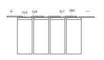
- the shoulder 329 of the outer can is used as the negative terminal, and multiple cylindrical batteries 310 are all arranged in the same orientation. Therefore, the bus bars 385 connecting adjacent positive and negative terminals are arranged on the same axial side.
- the object of this disclosure is to provide a cylindrical battery that can reduce the electrical resistance when the shoulder of the outer can is used as the external terminal.
- the cylindrical battery of the present disclosure comprises an electrode body in which a first electrode and a second electrode are wound with a separator interposed therebetween, and at least a portion of the circumferential direction of the outermost surface is constituted by a core body of the first electrode, a bottomed cylindrical outer can that contains the electrode body, a sealing body that closes the opening of the outer can, and a current collector joined to both the core body located at the outermost surface and the inner surface of the outer can.
- the cylindrical battery disclosed herein can reduce resistance when the shoulder of the exterior can is used as an external terminal.
- FIG. 2 is an axial cross-sectional view of a cylindrical battery according to one embodiment of the present disclosure. 2 is a cross-sectional view taken along line AA in FIG. 1.
- FIG. 11 is an axial cross-sectional view of a cylindrical battery according to a modified example.
- FIG. 1 is a diagram illustrating a connection structure of multiple cylindrical batteries connected to each other within a battery pack, with the bottom of the exterior can being used as a negative terminal.
- FIG. 1 is a diagram illustrating a connection structure of cylindrical batteries connected to each other within a battery pack, with the shoulder of the exterior can being used as a negative terminal.
- the cylindrical battery according to the present disclosure may be a primary battery or a secondary battery. It may also be a battery using an aqueous electrolyte or a battery using a non-aqueous electrolyte.
- a non-aqueous electrolyte secondary battery (lithium ion battery) using a non-aqueous electrolyte is exemplified as the cylindrical battery 10, which is one embodiment, but the cylindrical battery according to the present disclosure is not limited to this, and the electrolyte may also be an aqueous electrolyte.
- FIG. 1 is an axial cross-sectional view of a cylindrical battery 10 according to one embodiment of the present disclosure.
- the cylindrical battery 10 comprises an electrode body 14, a bottomed cylindrical outer can 16 that houses the electrode body 14, a sealing body 17 that closes the opening of the outer can 16, and a current collector 40 that is disposed between the outermost surface of the electrode body 14 and the inner surface of the outer can 16.
- the outer can 16 houses a non-aqueous electrolyte together with the electrode body 14.
- the outer can 16 has an annular shoulder 29 at its upper end that is bent radially inward and extends inward.
- the outer can 16 also has an annular groove 22 formed in its side wall, and the sealing body 17 is supported by the groove 22 to close the opening of the outer can 16.
- the cylindrical battery 10 further includes a gasket 28 interposed between the exterior can 16 and the sealing body 17.
- the gasket 28 is a ring-shaped resin member attached to the outer periphery of the sealing body 17, and insulates the sealing body 17 from the exterior can 16.
- the gasket 28 also seals the gap between the exterior can 16 and the sealing body 17, sealing the inside of the battery.
- the gasket 28 is made of, for example, polyolefin.
- the non-aqueous electrolyte includes a non-aqueous solvent and an electrolyte salt dissolved in the non-aqueous solvent.
- esters, ethers, nitriles, amides, and mixed solvents of two or more of these are used as the non-aqueous solvent.
- the non-aqueous solvent may contain a halogen-substituted body in which at least a part of the hydrogen of these solvents is replaced with a halogen atom such as fluorine.
- the non-aqueous solvent include ethylene carbonate (EC), ethyl methyl carbonate (EMC), dimethyl carbonate (DMC), and mixed solvents thereof.
- EMC ethyl methyl carbonate
- DMC dimethyl carbonate
- mixed solvents thereof ethylene carbonate
- a lithium salt such as LiPF 6 is used as the electrolyte salt.
- the non-aqueous electrolyte is not limited to a liquid electrolyte, and may be
- the electrode body 14 has a positive electrode 11, a negative electrode 12, and a separator 13, and has a wound structure in which the positive electrode 11 and the negative electrode 12 are wound in a spiral shape with the separator 13 in between.
- the positive electrode 11, the negative electrode 12, and the separator 13 are all long strip-shaped bodies, and are alternately stacked in the radial direction of the electrode body 14 by being wound in a spiral shape.
- the negative electrode 12 is formed with dimensions slightly larger than the positive electrode 11 to prevent lithium precipitation. In other words, the negative electrode 12 is formed to be longer in the longitudinal direction and width direction than the positive electrode 11.
- the separator 13 is formed with dimensions at least slightly larger than the positive electrode 11, and for example, two separators 13 are arranged to sandwich the positive electrode 11.
- the positive electrode 11 has a long positive electrode core and a positive electrode mixture layer formed on at least one surface of the positive electrode core.
- the positive electrode core can be a foil of a metal that is stable in the potential range of the positive electrode 11, such as aluminum or an aluminum alloy, or a film with the metal disposed on the surface.
- the positive electrode mixture layer contains a positive electrode active material, a conductive agent such as acetylene black, and a binder such as polyvinylidene fluoride (PVdF), and is preferably formed on both sides of the positive electrode core.
- PVdF polyvinylidene fluoride
- a lithium transition metal composite oxide containing Ni, Co, Mn, Al, etc. is used as the positive electrode active material.
- the negative electrode 12 has a long negative electrode core and a negative electrode mixture layer formed on at least one surface of the negative electrode core.
- the negative electrode core can be made of a foil of a metal that is stable in the potential range of the negative electrode 12, such as copper or a copper alloy, or a film with such a metal disposed on the surface.
- the negative electrode mixture layer contains a negative electrode active material and a binder such as styrene-butadiene rubber (SBR) or PVdF, and is preferably formed on both sides of the negative electrode core.
- the negative electrode active material can be, for example, graphite or a silicon-containing compound.
- a positive electrode lead 20 is connected to the electrode body 14.
- the positive electrode lead 20 electrically connects the positive electrode 11 and the sealing body 17.
- the positive electrode lead 20 is joined to the positive electrode core by ultrasonic welding or the like.
- the positive electrode lead 20 extends from the positive electrode 11 through an opening in the insulating plate 18 toward the sealing body 17.
- One end of the positive electrode lead 20 is joined to the positive electrode core by ultrasonic welding or the like, and the other end of the positive electrode lead 20 is joined to the underside of the sealing body 17 by welding, ultrasonic welding or the like.
- the cylindrical battery 10 includes an insulating plate 19 disposed between the electrode body 14 and the bottom 31, and the electrode body 14 is insulated from the bottom 31.
- the negative electrode core includes an outermost peripheral surface portion 35 that constitutes at least a portion of the circumferential direction of the outermost peripheral surface of the electrode body 14.
- the current collector 40 is a metal plate member and is disposed between the radially outer surface of the outermost peripheral surface portion 35 and the inner peripheral surface of the outer can 16.
- FIG. 2 is a cross-sectional view of line A-A in FIG. 1. As shown in FIG.
- the outer surface of the radially outer side of the current collector 40 has a cross-sectional shape that is approximately arc-shaped, and the inner surface of the radially inner side of the current collector 40 also has a cross-sectional shape that is approximately arc-shaped.
- the current collector 40 is joined to the radially outer surface of the outermost peripheral surface portion 35 by ultrasonic welding or the like, and is joined to the inner peripheral surface of the outer can 16 by laser welding or the like.
- the negative electrode 12 and the cylindrical portion 39 of the outer can 16 are electrically connected via the current collector 40.
- the outer can 16 is generally made of a metal whose main component is iron, but may be made of a metal whose main component is aluminum or the like. As shown in FIG. 1, the outer can 16 has a cylindrical portion 39 and a bottom portion 31, and the cylindrical portion 39 includes an annular grooved portion 22 and an annular shoulder portion 29.
- the grooved portion 22 is formed by spinning a portion of the cylindrical portion 39 around its entire circumference to recess it radially inward.
- the shoulder portion 29 is formed when the upper end of the cylindrical portion 39 is bent radially inward and crimped to the peripheral portion 33 of the sealing body 17, and protrudes radially inward.
- the sealing body 17 is fixed to the outer can 16 by being clamped between the shoulder portion 29 and the grooved portion 22 via the gasket 28 by crimping.
- the grooved portion 22 is formed at a position a predetermined length away from the upper end of the outer can 16.
- the predetermined length is, for example, a length equivalent to 1 to 20% of the axial length of the outer can 16.
- the gasket 28 is strongly compressed by the shoulder portion 29, and a part of it extends radially inward from between the shoulder portion 29 and the sealing body 17.
- the sealing body 17 has a structure in which a terminal plate 23, a lower valve body 24, an insulating plate 25, an upper valve body 26, and a sealing plate 27 are layered in this order from the electrode body 14 side.
- Each member constituting the sealing body 17 has, for example, a disk or ring shape, and each member except for the insulating plate 25 is electrically connected to each other.
- the sealing plate 27 has a convex shape with the radial center portion protruding outward.
- the convex portion 27a of the sealing plate 27 includes a sloped portion formed in an annular shape and a flat top surface portion surrounded by the sloped portion.
- One or more air holes 27b are formed in the top surface portion.
- the lower valve body 24, insulating plate 25, and upper valve body 26 constitute a current interruption mechanism.
- the lower valve body 24 and upper valve body 26 are connected at their respective centers, with the insulating plate 25 interposed between their respective peripheral edges.
- the lower valve body 24 deforms and pushes the upper valve body 26 toward the sealing plate 27, causing it to break, thereby interrupting the current path between the lower valve body 24 and the upper valve body 26.
- the upper valve body 26 breaks, and gas is discharged from the ventilation hole 27b in the sealing plate 27.
- the positive electrode lead 20 is connected to the underside of the terminal plate 23, and the sealing plate 27, which is the top plate of the sealing body 17 electrically connected to the terminal plate 23, serves as the positive electrode terminal.
- the shoulder portion 29 of the tubular portion 39 which is electrically connected to the negative electrode 12 via the current collector plate 40, is used as the negative electrode terminal.
- the cylindrical battery 10 can be produced, for example, by the following procedure. First, an electrode body 14 is prepared in which at least a portion of the circumferential direction of the outermost surface is made of a negative electrode core, and a positive electrode lead 20 is joined to the positive electrode core by ultrasonic welding. Next, a current collector 40 is joined by ultrasonic welding to the outermost surface arrangement portion 35 of the negative electrode core that constitutes at least a portion of the circumferential direction of the outermost surface of the electrode body 14. The current collector 40 may be joined to the position of the negative electrode core that will become the outermost surface arrangement portion 35 before the negative electrode 11 is wound together with the positive electrode 12 and separator 13.
- the electrode body 14 is inserted into the cylindrical exterior can 16 with a bottom, and the exterior can 16 is either drawn to reduce its diameter, or a rod is inserted into the hollow portion of the electrode body 14 to press the current collector 40 against the inner circumferential surface of the exterior can 16. Then, with the current collector 40 in contact with the inner circumferential surface of the exterior can 16, a laser beam is irradiated from outside the exterior can 16 to join the current collector 40 and the inner circumferential surface of the exterior can 16.
- the positive electrode lead 20 is joined to the underside of the sealing body 17 by welding or ultrasonic welding. Finally, the opening of the outer can 16 is sealed with the sealing body 17 by crimping, completing the cylindrical battery 10.
- the current collector 40 is joined to both the outermost surface portion 35 of the negative electrode core located on the outermost surface of the electrode body 14 and the inner surface of the outer can 16. Therefore, when the shoulder 29 is used as the negative terminal, the current path from the current collector 40 to the shoulder 29 is shorter than the current path from the negative electrode lead connected to the bottom of the outer can to the shoulder. This reduces the electrical resistance of the cylindrical battery 10 when the shoulder 29 of the outer can 16 is used as the negative terminal.
- the current collector plate 40 is joined to the outermost peripheral surface arrangement portion 35 and the inner peripheral surface of the outer can 16 above the center position P1 of the electrode body 14 (the sealing body 17 side in the axial direction). This significantly reduces the electrical resistance of the cylindrical battery 10 when the shoulder portion 29 is used as the negative terminal.
- the current collector plate 40 is joined to the outermost peripheral surface placement portion 35 and the inner peripheral surface of the exterior can 16 above position P2, which is 1/3 of the length of the electrode body 14 from the upper end 14a on the sealing body 17 side. This makes it possible to more significantly reduce the electrical resistance of the cylindrical battery 10 when the shoulder portion 29 is used as the negative terminal.
- arrow A indicates the winding direction of the electrode body 14. If the length of the current collector plate 40 in the winding direction is 3 mm or more, it is easy to irradiate the laser light to the range in the circumferential direction where the current collector plate 40 is located, and laser welding can be performed easily and reliably. Also, if the axial length of the current collector plate 40 is 3 mm or more, it is easy to irradiate the laser light to the range in the axial direction where the current collector plate 40 is located, and laser welding can be performed easily and reliably. Also, if the length of the current collector plate 40 in the winding direction is 1/3 or less of the perimeter of the outermost surface of the electrode body 14, the electrode body 14 can be smoothly inserted into the outer can 16.
- the electrode body 14 can be smoothly inserted into the outer can 16, and the current collector 40 and the outer can 16 can be smoothly welded together. It is more preferable that the thickness of the current collector 40 is 50 ⁇ m or more and 150 ⁇ m or less.
- the current collector 40 is joined only to both the negative electrode core portion (outermost surface disposed portion 35) located on the outermost surface of the electrode body 14 and the inner surface of the tubular portion 39 of the outer can 16.
- the current collector 140 may have a first extension portion 141 that extends in the axial direction between the negative electrode core portion (outermost surface disposed portion 35) located on the outermost surface of the electrode body 14 and the inner surface of the outer can 16, and a second extension portion 142 that extends radially inward from the lower end of the first extension portion 141 and extends along the inner surface of the can bottom.
- the second extension 142 may be joined to the bottom 31 of the outer can 16 by resistance welding, laser welding, or the like. In this way, the electrical resistance of the cylindrical battery 110 can be reduced regardless of the connection structure of the battery pack. Therefore, a cylindrical battery with high output and high versatility can be realized.
- the current collector 40 be joined to the outermost surface arrangement portion 35 and the inner surface of the outer can 16 at multiple positions including a position above the center of the electrode body 14 and a position below the center of the electrode body.
- a cylindrical battery 10 has been described that can achieve high output when the shoulder 29 of the outer can 16 is used as a negative electrode terminal.
- An external lead such as a bus bar may be directly joined to the shoulder 29, or a metal member may be joined to the shoulder 29 as an intermediate member between the shoulder 29 and the external lead.
- the shoulder 29 of the outer can 16 can also be used as a positive electrode terminal. In other words, the shoulder 29 of the outer can 16 can be used as an external terminal for either the negative electrode or the positive electrode.
Landscapes
- Chemical & Material Sciences (AREA)
- Chemical Kinetics & Catalysis (AREA)
- Electrochemistry (AREA)
- General Chemical & Material Sciences (AREA)
- Connection Of Batteries Or Terminals (AREA)
- Sealing Battery Cases Or Jackets (AREA)
Abstract
Description
Claims (7)
- 第1電極と第2電極がセパレータを介して巻回されると共に、最外周面の周方向の少なくとも一部が前記第1電極の芯体で構成される電極体と、
前記電極体を収容する有底筒状の外装缶と、
前記外装缶の開口部を塞ぐ封口体と、
前記最外周面に位置する前記芯体と前記外装缶の内周面の両方に接合された集電板と、を備える円筒形電池。 - 前記集電板の厚さが、30μm以上200μmである、請求項1に記載の円筒形電池。
- 前記電極体の巻き方向における前記集電板の長さが3mm以上である、請求項1又は2に記載の円筒形電池。
- 前記電極体の巻き方向における前記集電板の長さが、前記最外周面の周長の1/3以下の長さである、請求項1又は2に記載の円筒形電池。
- 前記電極体の軸方向において、前記集電板の少なくとも一部が、前記電極体の中心位置よりも前記封口体側で前記芯体及び前記外装缶の内周面の両方に接合されている、請求項1又は2に記載の円筒形電池。
- 前記電極体の軸方向において、前記集電板の少なくとも一部が、前記電極体における前記封口体側の端から前記電極体の長さの1/3の位置よりも前記封口体側で前記芯体及び前記外装缶の内周面に接合されている、請求項5に記載の円筒形電池。
- 前記集電板が、前記電極体の軸方向に延在する第1延在部と、前記外装缶の底部の内面に沿って延在する第2延在部を含み、
前記第2延在部と前記内面が、接合されている、請求項1に記載の円筒形電池。
Priority Applications (2)
| Application Number | Priority Date | Filing Date | Title |
|---|---|---|---|
| JP2024574359A JPWO2024161920A1 (ja) | 2023-01-31 | 2024-01-10 | |
| CN202480008974.6A CN120513548A (zh) | 2023-01-31 | 2024-01-10 | 圆筒形电池 |
Applications Claiming Priority (2)
| Application Number | Priority Date | Filing Date | Title |
|---|---|---|---|
| JP2023-012507 | 2023-01-31 | ||
| JP2023012507 | 2023-01-31 |
Publications (1)
| Publication Number | Publication Date |
|---|---|
| WO2024161920A1 true WO2024161920A1 (ja) | 2024-08-08 |
Family
ID=92146522
Family Applications (1)
| Application Number | Title | Priority Date | Filing Date |
|---|---|---|---|
| PCT/JP2024/000261 Ceased WO2024161920A1 (ja) | 2023-01-31 | 2024-01-10 | 円筒形電池 |
Country Status (3)
| Country | Link |
|---|---|
| JP (1) | JPWO2024161920A1 (ja) |
| CN (1) | CN120513548A (ja) |
| WO (1) | WO2024161920A1 (ja) |
Citations (3)
| Publication number | Priority date | Publication date | Assignee | Title |
|---|---|---|---|---|
| JP2009170365A (ja) * | 2008-01-18 | 2009-07-30 | Sanyo Electric Co Ltd | 密閉電池 |
| WO2012105362A1 (ja) * | 2011-02-03 | 2012-08-09 | 三洋電機株式会社 | 非水電解液二次電池 |
| WO2012111061A1 (ja) * | 2011-02-16 | 2012-08-23 | パナソニック株式会社 | 電池および電池の製造方法 |
-
2024
- 2024-01-10 WO PCT/JP2024/000261 patent/WO2024161920A1/ja not_active Ceased
- 2024-01-10 JP JP2024574359A patent/JPWO2024161920A1/ja active Pending
- 2024-01-10 CN CN202480008974.6A patent/CN120513548A/zh active Pending
Patent Citations (3)
| Publication number | Priority date | Publication date | Assignee | Title |
|---|---|---|---|---|
| JP2009170365A (ja) * | 2008-01-18 | 2009-07-30 | Sanyo Electric Co Ltd | 密閉電池 |
| WO2012105362A1 (ja) * | 2011-02-03 | 2012-08-09 | 三洋電機株式会社 | 非水電解液二次電池 |
| WO2012111061A1 (ja) * | 2011-02-16 | 2012-08-23 | パナソニック株式会社 | 電池および電池の製造方法 |
Also Published As
| Publication number | Publication date |
|---|---|
| CN120513548A (zh) | 2025-08-19 |
| JPWO2024161920A1 (ja) | 2024-08-08 |
Similar Documents
| Publication | Publication Date | Title |
|---|---|---|
| KR101215377B1 (ko) | 비수 전해액 원통형 전지 | |
| US12347878B2 (en) | Cylindrical battery | |
| JP7422680B2 (ja) | ガスケット、及び円筒形電池 | |
| US20240322406A1 (en) | Cylindrical battery | |
| WO2022107712A1 (ja) | 円筒形電池 | |
| WO2021106728A1 (ja) | 密閉電池 | |
| US20240313305A1 (en) | Cylindrical battery | |
| WO2024162134A1 (ja) | 蓄電装置 | |
| WO2024161920A1 (ja) | 円筒形電池 | |
| WO2024095902A1 (ja) | 蓄電装置 | |
| WO2023189939A1 (ja) | 蓄電装置 | |
| CN116686146A (zh) | 圆筒形电池 | |
| WO2022138423A1 (ja) | 密閉型電池 | |
| WO2025047154A1 (ja) | 円筒形電池 | |
| EP4679615A1 (en) | Cylindrical battery | |
| WO2024161967A1 (ja) | 円筒形電池 | |
| US20260058328A1 (en) | Cylindrical battery | |
| WO2025028054A1 (ja) | 円筒形電池 | |
| US20250309422A1 (en) | Cylindrical battery | |
| WO2024161945A1 (ja) | 円筒形電池 | |
| WO2024181003A1 (ja) | 円筒形電池 | |
| WO2024181038A1 (ja) | 円筒形電池 | |
| WO2026070618A1 (ja) | 円筒形電池 | |
| WO2024157743A1 (ja) | 二次電池 | |
| WO2024181423A1 (ja) | 蓄電装置 |
Legal Events
| Date | Code | Title | Description |
|---|---|---|---|
| 121 | Ep: the epo has been informed by wipo that ep was designated in this application |
Ref document number: 24749876 Country of ref document: EP Kind code of ref document: A1 |
|
| ENP | Entry into the national phase |
Ref document number: 2024574359 Country of ref document: JP Kind code of ref document: A |
|
| WWE | Wipo information: entry into national phase |
Ref document number: 2024574359 Country of ref document: JP |
|
| WWE | Wipo information: entry into national phase |
Ref document number: 202480008974.6 Country of ref document: CN |
|
| WWP | Wipo information: published in national office |
Ref document number: 202480008974.6 Country of ref document: CN |
|
| NENP | Non-entry into the national phase |
Ref country code: DE |
|
| 122 | Ep: pct application non-entry in european phase |
Ref document number: 24749876 Country of ref document: EP Kind code of ref document: A1 |