WO2024161565A1 - 検査システム - Google Patents
検査システム Download PDFInfo
- Publication number
- WO2024161565A1 WO2024161565A1 PCT/JP2023/003273 JP2023003273W WO2024161565A1 WO 2024161565 A1 WO2024161565 A1 WO 2024161565A1 JP 2023003273 W JP2023003273 W JP 2023003273W WO 2024161565 A1 WO2024161565 A1 WO 2024161565A1
- Authority
- WO
- WIPO (PCT)
- Prior art keywords
- container
- liquid
- micro
- vibration
- inspection system
- Prior art date
- Legal status (The legal status is an assumption and is not a legal conclusion. Google has not performed a legal analysis and makes no representation as to the accuracy of the status listed.)
- Ceased
Links
Images


Classifications
-
- G—PHYSICS
- G01—MEASURING; TESTING
- G01N—INVESTIGATING OR ANALYSING MATERIALS BY DETERMINING THEIR CHEMICAL OR PHYSICAL PROPERTIES
- G01N21/00—Investigating or analysing materials by the use of optical means, i.e. using sub-millimetre waves, infrared, visible or ultraviolet light
- G01N21/84—Systems specially adapted for particular applications
- G01N21/88—Investigating the presence of flaws or contamination
- G01N21/90—Investigating the presence of flaws or contamination in a container or its contents
Definitions
- the present invention relates to an inspection system, an inspection method, and a recording medium.
- a system has been proposed for inspecting the presence of foreign objects in a liquid sealed in a container, in which the liquid in the container is made to flow, the behavior of floating objects in the liquid is observed, and any floating objects that ultimately rise to the surface are determined to be air bubbles, and any floating objects that sink are determined to be foreign objects (see, for example, Patent Document 1).
- the object of the present invention is to provide an inspection system that solves the problem of reduced inspection efficiency.
- An inspection system includes: An inspection system for inspecting the presence or absence of foreign matter in a liquid sealed in a container, comprising: A flow inducing means for causing the liquid in the container to flow; A micro-vibration imparting means for micro-vibrating the container in which the liquid flows; a first detection means for detecting and tracking floating matter present in the liquid in a time series of images obtained by continuously photographing the liquid in the container during the micro-vibration with a camera, and detecting the presence or absence of a foreign matter based on the movement trajectory of the tracked floating matter;
- the device is configured to include:
- An inspection method includes the steps of: 1.
- a method for inspecting the presence or absence of foreign matter in a liquid sealed in a container comprising: causing the liquid in the container to flow; The container in which the liquid flows is slightly vibrated, detecting and tracking floating matter present in the liquid in a time series of images obtained by continuously photographing the liquid in the container during the micro-vibration with a camera, and detecting the presence or absence of a foreign matter based on the movement trajectory of the tracked floating matter; It is structured as follows.
- a computer-readable recording medium includes: A computer that checks for the presence of foreign objects in liquid sealed in a container A process of flowing the liquid in the container; A process of slightly vibrating the container in which the liquid flows; a process of detecting and tracking floating matter present in the liquid in a time series of images obtained by continuously photographing the liquid in the container during the micro-vibration with a camera, and detecting the presence or absence of a foreign matter based on the movement trajectory of the tracked floating matter;
- the recording medium is configured to record a program for causing the recording medium to perform the above steps.
- the present invention can shorten the time until behavior specific to foreign matter, such as settling, is observed, thereby improving inspection efficiency.
- FIG. 1 is a schematic diagram showing a schematic configuration of an inspection system for carrying out an inspection method according to a first embodiment of the present invention
- 3 is an explanatory diagram of an example of a container to be inspected and a vibration direction in the first embodiment of the present invention.
- FIG. 1 is a block diagram showing an example of an information processing device according to a first exemplary embodiment of the present invention.
- 1A to 1C are diagrams illustrating an example of a configuration of a time-series image according to a first embodiment of the present invention.
- 5A to 5C are diagrams illustrating an example of a configuration of a corrected time-series image according to the first embodiment of the present invention.
- FIG. 4 is a diagram illustrating an example of a configuration of tracking information according to the first embodiment of the present invention.
- FIG. 4 is a diagram showing an example of a configuration of test result information according to the first embodiment of the present invention
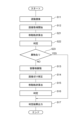
- FIG. 5 is a flowchart showing an example of pre-processing of the inspection system according to the first embodiment of the present invention.
- 5 is a flowchart showing an example of an inspection process performed by the inspection system according to the first embodiment of the present invention on a container to be inspected.
- FIG. 11 is a block diagram showing an example of an information processing device according to a second exemplary embodiment of the present invention.
- 10 is a flowchart showing an example of an inspection process performed by an inspection system according to a second embodiment of the present invention on a container to be inspected.
- FIG. 13 is a configuration diagram of a main part of an inspection system according to a fourth embodiment of the present invention.
- FIG. 13 is a configuration diagram of a main part of an inspection system according to a fifth embodiment of the present invention.
- FIG. 13 is a block diagram of an inspection system according to a sixth embodiment of the present invention
- shear-thickening fluids have the property that the viscosity decreases as the applied deformation rate (shear rate) increases (referred to as non-Newtonian viscosity characteristics).
- shear-thinning fluids are Bingham fluids (such as fresh cream and butter) and pseudoplastic fluids (such as polymer solutions). In this way, liquids with non-Newtonian viscosity characteristics decrease in viscosity as the applied deformation rate increases.
- the liquid to be inspected in this embodiment is a liquid that exhibits non-Newtonian viscosity characteristics as described above. As long as the liquid exhibits non-Newtonian viscosity characteristics, the type of liquid is not important.
- the liquid may be a liquid medicine or drinking water.
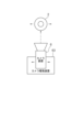
- FIG. 1 is a schematic diagram showing the general configuration of an inspection system 1 that performs an inspection method according to a first embodiment of the present invention.
- the inspection system 1 is a system that inspects the presence or absence of foreign matter in a liquid sealed in a container 2.
- the main components of the inspection system 1 include a flow inducing device 3, a micro-vibration imparting device 4, a lighting device 5, a camera device 6, and an information processing device 7.
- the container 2 is a transparent or semi-transparent container of a roughly cylindrical shape, such as a glass bottle.
- the inside of the container 2 is sealed or filled with a transparent or semi-transparent liquid exhibiting non-Newtonian viscosity characteristics.
- the container 2 is a syringe or a vial filled with a liquid medicine exhibiting non-Newtonian viscosity characteristics.
- foreign matter is mixed into the liquid sealed in such a container 2. Examples of foreign matter include glass fragments, metal fragments, rubber fragments, hair, fiber fragments, soot, and the like.
- the inspection system 1 uses a flow inducer 3 to cause the liquid in the container 2 to flow, making it possible to observe foreign objects as suspended matter.
- the flow inducing device 3 may be, for example, a device configured to include a container gripping part that grips the container 2 in an upright position, and a rotation mechanism that rotates the container gripping part around a center line that passes through the center of the bottom of the container 2 to the center of the head.
- the flow inducing device 3 may be a device configured to include a container gripping part that grips the container 2 in an upright position, and a tilting mechanism that repeatedly tilts the container gripping part so that the axis of the container 2 is tilted in a predetermined direction, and then returns it to the upright position.
- the flow inducing device 3 may be a device of any configuration as long as it is a device that can cause the liquid sealed in the container 2 to flow.
- the micro-vibration imparting device 4 is a device that imparts micro-vibrations to the container 2.
- the micro-vibration imparting device 4 is configured to impart micro-vibrations to the container 2 along a pre-determined micro-vibration trajectory.
- the micro-vibration trajectory is defined by a total of three parameters: the direction ⁇ of the micro-vibration, the frequency f, and the amount of displacement ⁇ d.
- the direction ⁇ of the micro-vibration is preferably a direction that vibrates the entire liquid in the container 2 more uniformly.
- a direction can be roughly determined by the shape of the container 2.
- the container 2 is a long and thin syringe, it is preferable to vibrate it in a direction perpendicular to the cylindrical axis.
- the cylindrical axis of the container 2 in a stationary state is the Z axis, and the axes perpendicular to that are the X axis and Y axis, it is preferable to vibrate the container 2 in a direction parallel to the XY plane.
- the trajectory of the micro-vibration is not limited to a straight line, and may be a curve such as an arc or ellipse.
- the frequency f and displacement ⁇ d of the micro-vibration determine the amount of kinetic energy imparted to the liquid in the container by the micro-vibration.
- the frequency f should be at least 10 Hz or more, and preferably 100 Hz or more.
- the frequency band of 100 Hz or more may or may not include the ultrasonic band.
- the micro-vibration imparting device 4 that imparts micro-vibrations to the container 2 along the micro-vibration orbit may have various configurations.
- the micro-vibration imparting device 4 may be a device that includes a container gripping part that grips the container 2 in an upright position, and a reciprocating vibration mechanism that reciprocates the container gripping part along the micro-vibration orbit in the range of + ⁇ d to - ⁇ d and at a frequency f.
- the reciprocating vibration mechanism may include, for example, a planar cam mechanism that converts the rotational motion of a rotary motor into reciprocating motion.
- the micro-vibration imparting device 4 may be a device that includes a container gripping part that grips the container 2 in an upright position, and a reciprocating rotation mechanism that reciprocates the container gripping part in the range of + ⁇ to - ⁇ ( ⁇ is, for example, 90° or less) and at a frequency f around a center line that passes through the center of the head of the container 2.
- the micro-vibration imparting device 4 may be a device of any configuration as long as it is a device that can impart micro-vibrations to the container 2.
- the flow inducing device 3 and the micro-vibration imparting device 4 may share a container gripping part for gripping the container 2, or they may be independent. By sharing the container gripping part between both devices, the effort and time required to transfer the container 2 between the devices can be reduced.
- the rotation mechanism of the flow inducing device 3 and the reciprocating rotation mechanism of the micro-vibration imparting device 4 may also be shared.
- the container 2 may be repeatedly rotated, for example, in +360° and -360° directions by a rotation mechanism that rotates the container 2 around a center line that passes through the center of the head from the center of the bottom of the container 2, to induce the flow of the liquid, and the container 2 may be repeatedly rotated, for example, in +90° and -90° directions to impart micro-vibrations.
- the lighting device 5 is configured to irradiate illumination light onto the liquid flowing inside the container 2 to be inspected.
- the lighting device 5 is, for example, a spot light source of a size that can illuminate the entire liquid inside the container 2 to be inspected.
- the lighting device 5 is installed on the same side as the side on which the camera device 6 is installed, or on the opposite side, as viewed from the container 2. In other words, the illumination provided by the lighting device 5 is transmitted illumination or reflected illumination. In the following description, the lighting device 5 is assumed to be installed on the opposite side, as viewed from the container 2, from the side on which the camera device 6 is installed.
- the camera device 6 is an imaging device that continuously captures images of the liquid flowing in the container 2 at a predetermined frame rate from a fixed position on the opposite side of the container 2 from the side on which the lighting device 5 is installed.
- the predetermined frame rate may be, for example, less than 100 fps or more than 100 fps.
- the camera device 6 may be, for example, a color camera or a black-and-white camera equipped with a CCD (Charge-Coupled Device) image sensor or a CMOS (Complementary MOS) image sensor having a pixel capacity of several million pixels.
- the exposure time of the camera device 6 is sufficiently short compared to the imaging cycle.
- the camera device 6 is connected to the information processing device 7 by wire or wirelessly.
- the camera device 6 is configured to transmit the time-series images obtained by imaging to the information processing device 7 together with information indicating the imaging time, etc.
- the information processing device 7 is configured to perform image processing on the time series of images captured by the camera device 6, and to inspect the presence or absence of foreign matter in the liquid sealed in the container 2.
- the information processing device 7 is connected to the flow inducing device 3, the micro-vibration imparting device 4, the lighting device 5, and the camera device 6 by wire or wirelessly.
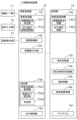
- FIG. 3 is a block diagram showing an example of an information processing device 7.
- the information processing device 7 includes a communication I/F unit 71, an operation input unit 72, a screen display unit 73, a memory unit 74, and a calculation processing unit 75.
- the communication I/F unit 71 is composed of a data communication circuit and is configured to perform data communication via wired or wireless connection with the flow inducing device 3, the micro-vibration imparting device 4, the lighting device 5, the camera device 6, and other external devices (not shown).
- the operation input unit 72 is composed of operation input devices such as a keyboard and a mouse, and is configured to detect the operation of the operator and output it to the calculation processing unit 75.
- the screen display unit 73 is composed of a screen display device such as an LCD (Liquid Crystal Display) or a PDP (Plasma Display Panel), and is configured to display various information such as test results on the screen in response to instructions from the calculation processing unit 75.
- the storage unit 74 is composed of one or more storage devices of one or more types, such as a hard disk or memory, and is configured to store processing information and programs 741 required for various processes in the arithmetic processing unit 75.
- the programs 741 are programs that are loaded into the arithmetic processing unit 75 and executed to realize various processing units, and are loaded in advance from an external device or recording medium (not shown) via a data input/output function such as the communication I/F unit 71 and stored in the storage unit 74.
- the main processing information stored in the storage unit 74 includes pre-processing information 742, time-series images 743, corrected time-series images 744, tracking information 745, and inspection result information 746.
- the pre-processing information 742 includes various information determined prior to the inspection of the container 2.
- the pre-processing information 742 includes micro-vibration trajectory information 7421 and a blur correction function 7422.
- the micro-vibration trajectory information 7421 is information that represents the trajectory along which the micro-vibration imparting device 4 micro-vibrates the container 2. Specifically, the micro-vibration trajectory information 7421 is defined by a total of three parameters: the direction ⁇ of the micro-vibration, the frequency f, and the amount of displacement ⁇ d.
- the blur correction function 7422 is a function used to correct blur in an image captured by the camera device 6.
- image blur occurs due to the movement of the captured object.
- the blurring that occurs in this way is called motion blur.
- f(x, y) is the original image
- g(x, y) is the degraded image
- h(x, y) is the PSF (Point Spread Function)
- *' is convolution.
- the above PSF is used as the blur correction function 7422.
- the image blur correction process is a deconvolution process of the image using the blur correction function 7422.
- the time series images 743 include a time series of images obtained by continuously capturing images of the liquid in the container 2 during micro-vibration using the camera device 6. If there is any floating matter in the liquid in the container 2, the image of the floating matter will be captured in the time series images 743.
- FIG. 4 shows an example of the configuration of a time-series image 743.
- the time-series image 743 in this example is composed of entries each consisting of a container ID 7431, a shooting time 7432, and a frame image 7433.
- An ID that uniquely identifies the container 2 to be inspected is set in the container ID 7431 item.
- the container ID may be a serial number assigned to the container 2, a barcode attached to the container 2, or fingerprint information collected from the cap of the container 2.
- the shooting time 7432 and frame image 7433 items are set with a shooting time and a frame image.
- the shooting time 7432 is set with an accuracy (for example, milliseconds) that allows the shooting time to be distinguished from other adjacent frame images.
- a container ID is associated with each frame image 7433, but a container ID may be associated with each group of multiple frame images 7433.
- the corrected time-series image 744 includes frame images after image blurring that has occurred in the frame images 7433 included in the time-series image 743 has been corrected.
- FIG. 5 shows an example of the configuration of the corrected time-series image 744.
- the corrected time-series image 744 is composed of entries consisting of a container ID 7441, a shooting time 7442, and a corrected frame image 7443.
- the container ID 7431 and shooting time 7432 that are the same as those of the frame image 7433 that was the subject of correction are set in the container ID 7441 and shooting time 7442 items.
- the blur-corrected frame image is set in the corrected frame image 7443 item.
- a container ID is associated with each corrected frame image 7443, but a container ID may also be associated with each group of multiple corrected frame images 7443.
- the tracking information 745 includes information according to the results of detecting and tracking floating matter present in the liquid in the container 2 based on the corrected time-series image 744.
- FIG. 6 shows an example of the configuration of the tracking information 745.
- the tracking information 745 is composed of the entries of a container ID 7451 and a pair of a tracking ID 7452 and a pointer 7453.
- an ID that uniquely identifies the container 2 is set.
- An entry consisting of a pair of a tracking ID 7452 and a pointer 7453 is provided for each floating matter to be tracked.
- an ID is set for identifying the floating matter to be tracked from other floating matter in the same container 2.
- a pointer to the movement trajectory information 7454 of the floating matter to be tracked is set.
- the movement trajectory information 7454 is composed of entries each consisting of a pair of time 74541 and position information 74542.
- the time 74541 and position information 74542 items contain the image capture time and coordinate values indicating the position of the tracking target floating object at that image capture time (for example, the position of the center of gravity of the floating object).
- the coordinate values may be, for example, coordinate values in a predetermined coordinate system.
- the predetermined coordinate system may be a camera coordinate system with the camera at its center, or a world coordinate system with a certain position in space as its center.
- the entries of the movement trajectory information 7454 are arranged in order of time 74541.
- the time 74541 of the first entry is the tracking start time.
- the time 74541 of the last entry is the tracking end time.
- the time 74541 of entries other than the first and last is the tracking midpoint time.
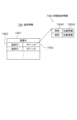
- the inspection result information 746 indicates the inspection result of the container 2.
- Figure 7 shows an example of the configuration of the inspection result information 746.
- the inspection result information 746 is composed of the entries of a container ID 7461 and an inspection result 7462.
- the entry for container ID 7461 is set with an ID that uniquely identifies the container 2 that has completed the inspection.
- the entry for inspection result 7462 is set with an inspection result of either OK (inspection passed) or NG (inspection failed).
- OK indicates that no foreign matter was detected in the liquid in the container.
- NG indicates that a foreign matter was detected in the liquid in the container.
- the calculation processing unit 75 has a processor such as a CPU (Central Processing Unit) and its peripheral circuits, and is configured to read and execute a program 741 from the storage unit 74, thereby implementing various processing units through cooperation between the above hardware and the program 741.
- the main processing units implemented by the calculation processing unit 75 include a pre-processing unit 751, a flow inducing unit 752, a micro-vibration applying unit 753, a detection unit 754, and an output control unit 755.
- the pre-processing unit 751 is configured to perform pre-processing before inspecting the container 2.
- the pre-processing unit 751 includes a micro-vibration trajectory determination unit 7511 and a blur correction function construction unit 7512.
- the micro-vibration trajectory determination unit 7511 is configured to determine a trajectory for micro-vibrating the container 2. That is, the micro-vibration trajectory determination unit 7511 determines a total of three parameters, the direction ⁇ , frequency f, and displacement amount ⁇ d for micro-vibrating the container 2. For example, the micro-vibration trajectory determination unit 7511 stores a direction correspondence table in which suitable candidates for the direction ⁇ are associated with each type of container 2, and determines the direction ⁇ according to the input type of container (such as a syringe) through interactive processing with the operator via the operation input unit 72 and the screen display unit 73.
- the input type of container such as a syringe
- the micro-vibration trajectory determination unit 7511 stores a frequency/displacement correspondence table in which suitable candidates for the combination of frequency f and displacement amount ⁇ d are associated with each classification of liquid viscosity, and determines the combination of frequency f and displacement amount ⁇ d according to the classification of liquid viscosity through interactive processing with the operator. Based on the micro-vibration trajectory determined by the micro-vibration trajectory determination unit 7511, the operator selects the micro-vibration imparting device 4 to be incorporated into the inspection system 1 from among multiple micro-vibration imparting devices prepared in advance, and installs it in the inspection system 1 before inspecting the container 2. In addition, the micro-vibration trajectory determination unit 7511 stores the above three parameters of the determined micro-vibration trajectory in the memory unit 74 as micro-vibration trajectory information 7421.
- the blur correction function constructing unit 7512 is configured to construct a blur correction function based on the micro-vibration trajectory information 7421 determined by the micro-vibration trajectory determining unit 7511. For example, when constructing the PSF in the above-mentioned formula 1 as the blur correction function, the blur correction function constructing unit 7512 determines the PSF from the direction ⁇ of the micro-vibration and the displacement amount ⁇ d. The blur correction function constructing unit 7512 stores the constructed blur correction function in the memory unit 74 as the blur correction function 7422.
- the flow inducing unit 752 is configured to induce the flow of the liquid in the container 2 by the flow inducing device 3 by sending a flow start command to the flow inducing device 3 through the communication I/F unit 71.
- the flow inducing unit 752 is also configured to stop the induction of the liquid flow by the flow inducing device 3 by sending a flow stop command to the flow inducing device 3 through the communication I/F unit 71. Note that even if the induction of the liquid flow by the flow inducing device 3 is stopped, the liquid in the container 2 will continue to flow for a while thereafter due to inertia.
- the micro-vibration imparting unit 753 is configured to start micro-vibration of the container 2 by the micro-vibration imparting device 4 by sending a micro-vibration start command to the micro-vibration imparting device 4 through the communication I/F unit 71.
- the micro-vibration imparting unit 753 is also configured to stop micro-vibration of the container 2 by the micro-vibration imparting device 4 by sending a micro-vibration stop command to the micro-vibration imparting device 4 through the communication I/F unit 71.
- the detection unit 754 is configured to detect and track floating objects present in the liquid in time-series images obtained by continuously photographing the liquid in the container 2 while it is being micro-vibrated by the micro-vibration imparting device 4 using the camera device 6, and to detect the presence or absence of foreign objects based on the movement trajectory of the tracked floating objects.
- the detection unit 754 is configured to include a time-series image acquisition unit 7541, an image blur correction unit 7542, and a determination unit 7543.
- the time-series image acquisition unit 7541 is configured to start a process of continuously capturing images of the liquid flowing in the container 2 under micro-vibration by the camera device 6 at a predetermined frame rate under the illumination of the lighting device 5 by sending an image capture start command to the camera device 6 via the communication I/F unit 71.
- the time-series image acquisition unit 7541 is also configured to generate a time-series image 743 as shown in FIG. 4 from the captured time-series images and store it in the memory unit 74.
- the time-series image acquisition unit 7541 is also configured to end image capture by the camera device 6 by sending an image capture end command to the camera device 6 via the communication I/F unit 71.
- the image blur correction unit 7542 is configured to read out the time series image 743 and the blur correction function 7422 from the memory unit 74, and perform deconvolution processing of each frame image 7433 in the time series image 743 using the blur correction function 7422 as shown in the following equation.
- D I*H...(2)
- I the input image
- H the blur correction function
- * is deconvolution.
- the image blur correction unit 7452 is configured to store in the storage unit 74 the corrected time-series image 744 including the corrected frame image 7443 generated and obtained by the above process.
- the determination unit 7543 is configured to read the corrected time series image 744 from the storage unit 74, detect and track floating matter present in the liquid in the time series corrected frame image 7443 by processing such as binarization, and store tracking information 745 including the movement trajectory of the tracked floating matter in the storage unit 74. For example, the determination unit 7543 extracts all corrected frame images from the corrected time series image 744 shown in FIG. 5, and calculates all movement trajectory information 7454 of floating matter present in the liquid in the container 2 from the time series of the extracted corrected frame images.
- the determination unit 7543 calculates tracking information 745 including the container ID 7451, a set of a tracking ID 7452 and a pointer 7453, and the calculated movement trajectory information 7454 of floating matter, and stores it in the storage unit 74.
- the determination unit 7543 is also configured to detect the presence or absence of a foreign object based on the tracking information 745. For example, the determination unit 7543 reads out the tracking information 745 from the storage unit 74, and for each tracking ID 7452 of the floating object included in the tracking information 745, determines whether the floating object is an air bubble or a foreign object based on the characteristics of the movement trajectory of the floating object represented by the movement trajectory information 7454 specified by the pointer 7453 corresponding to the tracking ID 7452. Whether a floating object is a foreign object or an air bubble can be determined based on the movement trajectory of the floating object because the characteristics of the movement trajectory of a foreign object in a liquid are different from the characteristics of the movement trajectory of an air bubble.
- the determination unit 7543 is also configured to generate inspection result information 746 based on the detection results and store it in the memory unit 74. For example, when the determination unit 7543 determines that at least one floating object is a foreign object, it creates inspection result information 746 consisting of a container ID 7461 and an NG inspection result 7462 and stores it in the memory unit 74. When the determination unit 7543 determines that all floating objects are air bubbles, it creates inspection result information 746 consisting of a container ID 7461 and an OK inspection result 7462 and stores it in the memory unit 74.
- the output control unit 755 is configured to read the test result information 746 generated by the detection unit 754 from the storage unit 74, display it on the screen display unit 73, and/or transmit it to an external device (not shown) via the communication I/F unit 71.
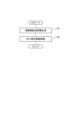
- FIG. 8 is a flow chart showing an example of pre-processing of the inspection system 1.
- the inspection system 1 Prior to the actual inspection of the container 2, the inspection system 1 performs the processing shown in FIG. 8 using the pre-processing unit 751.
- the micro-vibration trajectory determination unit 7511 of the pre-processing unit 751 determines a total of three parameters, namely the direction ⁇ , frequency f, and displacement amount ⁇ d for micro-vibrating the container 2, and stores the above three parameters of the determined micro-vibration trajectory in the memory unit 74 as micro-vibration trajectory information 7421 (step S1).
- the blur correction function construction unit 7512 of the pre-processing unit 751 constructs a blur correction function 7422 based on the micro-vibration trajectory information 7421 determined by the micro-vibration trajectory determination unit 7511, and stores it in the memory unit 74 (step S2).
- FIG. 9 is a flowchart showing an example of the inspection process performed by the inspection system 1 on the container to be inspected.
- the flow inducing unit 752 induces the flow of the liquid in the container 2 by sending a flow start command to the flow inducing device 3 (step S11).
- the time-series image acquiring unit 7541 of the detecting unit 754 starts the process of continuously photographing the flowing liquid in the container 2 at a predetermined frame rate by sending a shooting start command to the camera device 6 with the lighting device 5 turned on (step S12).
- the micro-vibration applying unit 753 transmits a micro-vibration start command to the micro-vibration applying device 4 simultaneously with or around the start of the above-mentioned shooting, thereby micro-vibrating the container 2 containing the flowing liquid along a predetermined micro-vibration trajectory (step S13).
- the flow inducing unit 752 transmits a flow stop command to the flow inducing device 3 in synchronization with the start of the micro-vibration.
- the container 2 is micro-vibrated in a stationary position.
- the flow inducing unit 752 may transmit the flow stop command to the flow inducing device 3 at any time thereafter, rather than at the start of the micro-vibration. In other words, the container 2 may be vibrated while it is tilted and rocked.
- the time-series image acquisition unit 7541 of the detection unit 754 receives the frame images 7433 captured by the camera device 6 in real time from the camera device 6 via the communication I/F unit 71, adds the ID 7431 of the container 2 to be inspected and the capture time 7432, and adds them to the time-series image 743.
- the image blur correction unit 7542 applies the blur correction function 7422 to the added frame image 7433 to perform blur correction, and adds it to the corrected time-series image 744 as a corrected frame image 7443 (step S14).
- the determination unit 7543 detects floating matter from the added corrected frame image 7443, determines whether it is the same as floating matter detected so far, and calculates a movement trajectory (step S15). Specifically, when the determination unit 7543 detects a new floating matter floating in the liquid, it generates a new pair of a tracking ID 7452 and a pointer 7453, secures one entry in the movement trajectory information 7454 indicated by the pointer 7453, and sets the shooting time 74541 of the frame in which the new floating matter was detected and the position information 74542 of the detected floating matter.
- the determination unit 7543 determines whether the floating matter is an air bubble or a foreign object based on the movement trajectory information 7454 (step S16). Then, when the determination unit 7543 determines that at least one floating matter is not an air bubble but a foreign object, it generates inspection result information 746 including an NG inspection result 7462 and stores it in the storage unit 74. Then, at this point, the inspection system 1 ends the inspection of the container 2 to be inspected. Accordingly, the micro-vibration applying unit 753 sends a vibration end command to the micro-vibration applying device 4, and the time-series image acquisition unit 7541 sends an image capture end command to the camera device 6.
- the determination unit 7543 calculates the difference between the shooting time 7442 at the beginning of the corrected time series image 744 and the current time, and if this difference is less than the inspection time T seconds, the inspection time is still in progress and the determination unit 7543 waits for the next update of the movement trajectory information.
- the inspection time T seconds may be determined before the inspection by determining the type and size of all foreign objects that may be mixed in, using the following method.
- Determination method 1 A foreign object is actually mixed into the liquid in the container 2, and the time until all of the foreign object settles is measured, and T seconds is determined based on the measurement result.
- Determination method 2 When the viscosity of the liquid is known, the time required for all foreign matter to settle is calculated based on the settling velocity of the particles by gravitational settling method, and T seconds is determined based on the calculation result.
- the determination unit 7543 determines that no foreign matter was detected, and generates inspection result information 746 including an OK inspection result 7462, and stores it in the memory unit 74.
- the inspection system 1 ends the inspection of the container 2 being inspected. Accordingly, the micro-vibration applying unit 753 sends a vibration end command to the micro-vibration applying device 4, and the time-series image acquisition unit 7541 sends an image capture end command to the camera device 6.
- the output control unit 755 displays the test result information 746 on the screen display unit 73 and/or transmits it to an external device via the communication I/F unit 71 (step S17).
- this embodiment includes a flow inducing section 752 that causes the liquid in the container 2 to flow, a micro-vibration applying section 753 that micro-vibrates the container 2 in which the liquid is flowing, and a detection section 754 that detects and tracks floating objects present in the liquid in a time series of images obtained by continuously photographing the liquid in the container 2 during micro-vibration using the camera device 6, and detects the presence or absence of foreign objects based on the movement trajectory of the tracked floating objects. Therefore, since the behavior of the floating objects can be observed with the viscosity of the liquid sealed in the container 2 reduced, the time until behavior specific to foreign objects, such as settling, is observed can be shortened. This improves inspection efficiency.
- this embodiment includes an image blur correction unit 7542 that corrects blurring that occurs in the image captured by the camera device 6 due to micro-vibrations of the container 2. This allows for accurate detection and tracking of floating objects in the liquid without being affected by micro-vibrations.
- the inspection system 1A is different from the above-described inspection system 1 in that the inspection system 1A is divided into a non-vibration inspection in which the container 2 is inspected without being subjected to minute vibration, and an inspection with vibration in which the container 2 is inspected with minute vibration, and the inspection with vibration is omitted when a foreign object is detected in the non-vibration inspection.
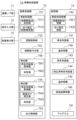
- FIG. 10 is a block diagram showing an example of an information processing device 7A used in the inspection system 1A, where the same reference numerals as in FIG. 3 indicate the same parts, with 747 being a time-series image, 748 being tracking information, 756 being a detection unit, 7561 being a time-series image acquisition unit, and 7562 being a judgment unit.
- Time series image 747 includes a time series of images obtained by continuously capturing images of the liquid in container 2 that is not being subjected to micro-vibration using camera device 6. If floating objects are present in the liquid in container 2, the image of the floating objects will be captured in time series image 747.
- the configuration of time series image 747 is the same as the configuration of time series image 743 shown in FIG. 4. However, there is no image blurring due to micro-vibration in the frame images of time series image 747.
- Tracking information 748 includes information corresponding to the results of detecting and tracking floating matter present in the liquid in container 2 based on time-series image 747.
- the configuration of tracking information 748 is the same as the configuration of tracking information 745 shown in FIG. 6.
- the detection unit 756 is configured to detect and track floating objects present in the liquid in time-series images obtained by continuously photographing the liquid in the container 2 that is not vibrating with the camera device 6, and to detect the presence or absence of foreign objects based on the movement trajectory of the tracked floating objects.
- the detection unit 756 is configured to include a time-series image acquisition unit 7561 and a determination unit 7562.
- the time-series image acquisition unit 7561 is configured to start a process of continuously capturing images of the liquid flowing in the container 2 at a predetermined frame rate by the camera device 6 under the illumination of the lighting device 5 by sending an image capture start command to the camera device 6 via the communication I/F unit 71.
- the time-series image acquisition unit 7561 is also configured to generate a time-series image 747 as shown in FIG. 4 from the captured time-series images and store it in the storage unit 74.
- the time-series image acquisition unit 7561 is also configured to end image capture by the camera device 6 by sending an image capture end command to the camera device 6 via the communication I/F unit 71.
- the determination unit 7562 is configured to read the time series image 747 from the memory unit 74, detect and track floating objects present in the liquid in the time series frame images 7433, and store tracking information 748 including the movement trajectories of the tracked floating objects in the memory unit 74.
- the determination unit 7562 is also configured to detect the presence or absence of a foreign object based on the tracking information 748. For example, the determination unit 7562 reads out the tracking information 748 from the storage unit 74, and for each tracking ID 7452 of the floating object included in the tracking information 748, determines whether the floating object is an air bubble or a foreign object based on the characteristics of the movement trajectory of the floating object represented by the movement trajectory information 7454 specified by the pointer 7453 corresponding to the tracking ID 7452.
- the determination unit 7562 is also configured to generate inspection result information 746 when a foreign object is detected and store it in the memory unit 74. For example, when the determination unit 7562 determines that at least one floating object is a foreign object, it creates inspection result information 746 consisting of a container ID 7461 and an NG inspection result 7462 and stores it in the memory unit 74. On the other hand, if no foreign object is detected within the inspection time T1 of the first half process, the determination unit 7562 ends the detection process by the detection unit 756. At this time, the detection process is transferred to the detection unit 754.
- FIG. 11 is a flowchart showing an example of an inspection process performed by the inspection system 1A on a container to be inspected.
- the flow inducing unit 752 induces a flow of the liquid in the container 2 by sending a flow start command to the flow inducing device 3 (step S11).
- the time-series image acquiring unit 7561 of the detecting unit 756 starts a process of continuously photographing the flowing liquid in the container 2 at a predetermined frame rate by sending a shooting start command to the camera device 6 with the lighting device 5 turned on (step S12).
- the micro-vibration imparting device 4 is not activated, the container 2 containing the flowing liquid is not micro-vibrated. That is, a non-vibration inspection is performed first.
- the time-series image acquisition unit 7561 of the detection unit 756 receives the frame images 7433 captured by the camera device 6 in real time through the communication I/F unit 71 from the camera device 6, adds the ID 7431 of the container 2 to be inspected and the capture time 7432, and adds them to the time-series image 747. As soon as a new frame image 7433 is added to the time-series image 747, the determination unit 7562 detects floating matter from the added frame image 7433, determines whether it is the same as the floating matter detected so far, and calculates the movement trajectory (step S21).
- the determination unit 7562 when the determination unit 7562 detects a new floating matter floating in the liquid, it generates a new pair of a tracking ID 7452 and a pointer 7453, and secures one entry in the movement trajectory information 7454 indicated by the pointer 7453, and sets the capture time 74541 of the frame in which the new floating matter was detected and the position information 74542 of the detected floating matter.
- a new entry is added to the movement trajectory information 7454 of the floating object determined to be the same, and the shooting time 7454 of the current frame and the position information 74542 of the detected floating object are set.
- the determination unit 7562 determines whether the floating matter is an air bubble or a foreign matter based on the movement trajectory information 7454 (step S22). Then, when the determination unit 7562 determines that at least one floating matter is not an air bubble but a foreign matter (YES in step S23), it generates inspection result information 746 including an NG inspection result 7462 and stores it in the memory unit 74 (step S17). Then, at this point, the inspection system 1A ends the inspection of the container 2 to be inspected. That is, the inspection system 1A ends the inspection by skipping the vibration inspection. Accordingly, the time-series image acquisition unit 7561 sends an image capture end command to the camera device 6.
- the determination unit 7562 calculates the difference between the shooting time 7432 of the first image in the time series 743 and the current time, and if this difference is less than the vibration-free inspection time T1 seconds, it waits for the movement trajectory information to be updated next because it is still within the vibration-free inspection period.
- the vibration-free inspection time T1 seconds determines the type and size of foreign objects (glass fragments or metal fragments) that have the property of settling quickly (hereinafter referred to as heavy foreign objects) among all foreign objects that may be mixed in, and may be determined before inspection in the following manner.
- Determination method 1 A heavy foreign object is actually mixed into the liquid in the container 2, and the time until all of the heavy foreign object settles is measured, and T1 seconds is determined based on the measurement result.
- Determination method 2 When the viscosity of the liquid is known, the time it takes for a heavy foreign object to settle is calculated based on the settling velocity of the particle by gravitational settling method, and T1 seconds is determined based on the calculation result.
- the determination unit 7543 ends the detection process of the detection unit 756. In other words, the inspection system 1A ends the vibration-free inspection and immediately starts the vibration-free inspection.
- the micro-vibration applying unit 753 transmits a micro-vibration start command to the micro-vibration applying device 4 to micro-vibrate the container 2 containing the flowing liquid along a predetermined micro-vibration trajectory (step S13).
- the time-series image acquisition unit 7541 of the detection unit 754 receives the frame images 7433 captured by the camera device 6 in real time from the camera device 6 through the communication I/F unit 71, adds the ID 7431 of the container 2 to be inspected and the capture time 7432, and adds them to the time-series image 743.
- the image blur correction unit 7542 applies the blur correction function 7422 to the added frame image 7433 as soon as the new frame image 7433 is added to the time-series image 743, thereby performing blur correction, and adds the image to the corrected time-series image 744 as a corrected frame image 7443 (step S14).
- the determination unit 7543 detects floating objects from the added corrected frame image 7443, determines whether the floating objects are identical to the floating objects detected so far, and calculates the movement trajectory (step S15). In addition, as soon as the movement trajectory information 7454 is updated, the determination unit 7543 determines whether the floating objects are air bubbles or foreign objects based on the movement trajectory information 7454 (step S16). Then, when the determination unit 7543 determines that at least one floating object is not an air bubble but a foreign object, it generates inspection result information 746 including an NG inspection result 7462 and stores it in the storage unit 74 (step S17).
- the inspection system 1 ends the inspection of the container 2 to be inspected. Accordingly, the micro-vibration applying unit 753 transmits a vibration end command to the micro-vibration applying device 4, and the time-series image acquisition unit 7541 transmits an image capture end command to the camera device 6.
- the determination unit 7543 calculates the difference between the shooting time 7442 of the first corrected time-series image 744 and the current time, and if this difference is less than the vibration inspection time T2 seconds, the vibration inspection time is still in progress and the determination unit 7543 waits for the next update of the movement trajectory information.
- the vibration inspection time T2 seconds determines the type and size of foreign objects (hereinafter referred to as lightweight foreign objects) other than those that have the property of settling quickly (glass fragments and metal fragments) among all foreign objects that may be mixed in, and may be determined before inspection in the following manner.
- Determination method 1 Light weight foreign matter is actually mixed into the liquid in the container 2, and the time until all the light weight foreign matter settles is measured, and T2 seconds is determined based on the measurement result.
- Determination method 2 When the viscosity of the liquid is known, the time required for all the light foreign matter to settle is calculated based on the settling velocity of the particles using the gravitational settling method, and T2 seconds is determined based on the calculation result.
- the determination unit 7543 determines that no foreign object was detected, and generates inspection result information 746 including an OK inspection result 7462, and stores it in the memory unit 74.
- the inspection system 1 ends the inspection of the container 2 being inspected. Accordingly, the micro-vibration applying unit 753 sends a vibration end command to the micro-vibration applying device 4, and the time-series image acquisition unit 7541 sends an image capture end command to the camera device 6.
- the output control unit 755 displays the test result information 746 on the screen display unit 73 and/or transmits it to an external device via the communication I/F unit 71 (step S17).
- this embodiment is divided into a non-vibration inspection in which the container 2 is inspected without vibrating it, and a vibration inspection in which the container 2 is inspected with vibrating it.
- the non-vibration inspection is carried out first to check for the presence or absence of heavy foreign matter.
- Heavy foreign matter has the property of settling quickly, so it basically tends to settle quickly even in the original viscous liquid without vibration. Therefore, it is possible to detect the foreign matter early on in a container 2 containing heavy foreign matter by non-vibration inspection alone.
- vibration is applied from the beginning as in the inspection system 1 to reduce the viscosity of the liquid, the heavy foreign matter can be made to settle more quickly.
- the vibration test is omitted. Furthermore, in the vibration test, the behavior of floating objects is observed in a state where the viscosity of the liquid sealed in the container 2 is reduced, so the time until behavior specific to foreign objects, such as settling, is observed can be shortened. This improves the efficiency of the test.
- Inspection system 1B differs from the first or second embodiment in that the photographing period (1/frame rate) of camera device 6 that photographs the liquid in container 2 during micro-vibration is set to an integer multiple (1x, 2x, ...) of the micro-vibration period (1/frequency f), but is otherwise the same as the first or second embodiment.
- the image blur correction unit 7542 may or may not be omitted.
- Fig. 12 is a diagram showing the main components of the inspection system 1C.
- the inspection system 1C differs from the first to third embodiments in that it further includes a mirror 61 that reflects an image of the container 2 and inputs it to the camera device 6, and a mirror driver 62 that drives the mirror 61 in response to the micro-vibration of the container 2, but is otherwise the same as the first to third embodiments.
- the micro-vibration trajectory of the container 2 is a straight line, but the micro-vibration trajectory may be a curve such as an arc or an ellipse.
- the image blur correction unit 7542 may or may not be omitted.
- FIG. 13 is a diagram showing the main components of the inspection system 1D.
- the inspection system 1D is different from the first to third embodiments in that it further includes a camera driving unit 63 that drives (vibrates) the camera device 6 in response to the micro-vibration of the container 2, and is otherwise the same as the first to third embodiments.
- the micro-vibration trajectory of the container 2 is a straight line, but the micro-vibration trajectory may be a curve such as an arc or an ellipse.
- the camera driving unit 63 may be configured to micro-vibrate the container 2 together with the camera device 6. That is, the camera driving unit 63 and the micro-vibration imparting device 4 may be shared.
- the image blur correction unit 7542 may or may not be omitted.
- FIG. 14 is a block diagram of an inspection system 100 according to this embodiment. This embodiment will explain the outline of the above-mentioned inspection system.
- the inspection system 100 is an inspection system that inspects the presence or absence of foreign matter in a liquid sealed in a container, and includes a flow inducing means 101, a micro-vibration applying means 102, and a detection means 103.
- the flow inducing means 101 is configured to cause the liquid in the container to flow.
- the flow inducing means 101 can be configured, for example, in the same manner as the flow inducing section 752 in FIG. 3 or FIG. 10.
- the micro-vibration imparting means 102 is configured to cause the container in which the liquid is flowing to vibrate micro-vibrations.
- the micro-vibration imparting means 102 can be configured, for example, in the same manner as the micro-vibration imparting section 753 in FIG. 3 or FIG. 10.
- the detection means 103 is configured to detect and track floating objects present in the liquid in a time series of images obtained by continuously photographing the liquid in the container during micro-vibration with a camera, and to detect the presence or absence of foreign objects based on the movement trajectory of the tracked floating objects.
- the detection means 103 can be configured, for example, in the same manner as the detection section 754 in FIG. 3 or FIG. 10.
- the inspection system 100 configured in this manner functions as follows. That is, first, the flow inducing means 101 causes the liquid in the container to flow. Next, the micro-vibration applying means 102 micro-vibrates the container in which the liquid is flowing. Next, the detection means 103 detects and tracks floating objects present in the liquid in a time series of images obtained by continuously photographing the liquid in the container during micro-vibration with a camera, and detects the presence or absence of foreign objects based on the movement trajectory of the tracked floating objects.
- the inspection system 100 configured and operating as described above can observe the behavior of floating objects while reducing the viscosity of the liquid sealed in the container by micro-vibrations, shortening the time until behavior specific to foreign objects, such as settling, is observed, improving inspection efficiency.
- the information processing device may use a GPU (Graphic Processing Unit), a DSP (Digital Signal Processor), an MPU (Micro Processing Unit), an FPU (Floating number Processing Unit), a PPU (Physics Processing Unit), a TPU (Tensor Processing Unit), a quantum processor, a microcontroller, or a combination of these.
- a GPU Graphic Processing Unit
- DSP Digital Signal Processor
- MPU Micro Processing Unit
- FPU Floating number Processing Unit
- PPU Physicals Processing Unit
- TPU Transsor Processing Unit
- quantum processor a microcontroller, or a combination of these.
- the present invention can be used in the general field of testing for the presence of foreign matter in liquids sealed in containers such as syringes and vials.
- An inspection system for inspecting the presence or absence of foreign matter in a liquid sealed in a container comprising: A flow inducing means for causing the liquid in the container to flow; A micro-vibration imparting means for micro-vibrating the container in which the liquid flows; a first detection means for detecting and tracking floating matter present in the liquid in a time series of images obtained by continuously photographing the liquid in the container during the micro-vibration with a camera, and detecting the presence or absence of a foreign matter based on the movement trajectory of the tracked floating matter;
- An inspection system comprising: [Appendix 2] a second detection means for detecting and tracking floating matter present in the liquid in a time series of images obtained by continuously photographing the liquid in the container during flow before the container is subjected to micro-vibration, and detecting the presence or absence of a foreign matter based on the movement trajectory of the tracked floating matter;
- the inspection system of claim 1 The method further includes a correction unit for correcting blurring caused in the time series images by the micro-vibration.
- the inspection system of claim 1. [Appendix 4] The correction means performs a deconvolution process on the image using a blur correction function constructed based on the trajectory of the micro-vibration. 4.
- the inspection system of claim 3. [Appendix 5] The blur correction function is a point spread function. 5.
- the blur correction function is generated based on a trajectory of the micro-vibration. 5.
- [Appendix 7] The camera captures images at a period that is an integer multiple of the vibration period of the micro-vibration. 2.
- the camera further includes a mirror that reflects an image of the container and inputs the image to the camera, and a mirror driver that drives the mirror in response to micro-vibrations of the container. 2.
- the inspection system of claim 1. [Appendix 9] Further comprising a camera driving unit that drives the camera in response to micro-vibrations of the container. 2.
- the inspection system of claim 1. [Appendix 10]
- the liquid is a liquid exhibiting non-Newtonian viscous properties. 10.
- a method for inspecting the presence or absence of foreign matter in a liquid sealed in a container comprising: causing the liquid in the container to flow; The container in which the liquid flows is slightly vibrated, detecting and tracking floating matter present in the liquid in a time series of images obtained by continuously photographing the liquid in the container during the micro-vibration with a camera, and detecting the presence or absence of a foreign matter based on the movement trajectory of the tracked floating matter; Testing method.
- Appendix 12 A computer that checks for the presence of foreign objects in liquid sealed in a container A process of flowing the liquid in the container; A process of slightly vibrating the container in which the liquid flows; a process of detecting and tracking floating matter present in the liquid in a time series of images obtained by continuously photographing the liquid in the container during the micro-vibration with a camera, and detecting the presence or absence of a foreign matter based on the movement trajectory of the tracked floating matter; A computer-readable recording medium having a program recorded thereon for causing a computer to carry out the above.
Landscapes
- Physics & Mathematics (AREA)
- Health & Medical Sciences (AREA)
- Life Sciences & Earth Sciences (AREA)
- Chemical & Material Sciences (AREA)
- Analytical Chemistry (AREA)
- Biochemistry (AREA)
- General Health & Medical Sciences (AREA)
- General Physics & Mathematics (AREA)
- Immunology (AREA)
- Pathology (AREA)
- Investigating Materials By The Use Of Optical Means Adapted For Particular Applications (AREA)
Priority Applications (2)
| Application Number | Priority Date | Filing Date | Title |
|---|---|---|---|
| JP2024574161A JPWO2024161565A1 (https=) | 2023-02-01 | 2023-02-01 | |
| PCT/JP2023/003273 WO2024161565A1 (ja) | 2023-02-01 | 2023-02-01 | 検査システム |
Applications Claiming Priority (1)
| Application Number | Priority Date | Filing Date | Title |
|---|---|---|---|
| PCT/JP2023/003273 WO2024161565A1 (ja) | 2023-02-01 | 2023-02-01 | 検査システム |
Publications (1)
| Publication Number | Publication Date |
|---|---|
| WO2024161565A1 true WO2024161565A1 (ja) | 2024-08-08 |
Family
ID=92146268
Family Applications (1)
| Application Number | Title | Priority Date | Filing Date |
|---|---|---|---|
| PCT/JP2023/003273 Ceased WO2024161565A1 (ja) | 2023-02-01 | 2023-02-01 | 検査システム |
Country Status (2)
| Country | Link |
|---|---|
| JP (1) | JPWO2024161565A1 (https=) |
| WO (1) | WO2024161565A1 (https=) |
Citations (7)
| Publication number | Priority date | Publication date | Assignee | Title |
|---|---|---|---|---|
| JP2011059813A (ja) * | 2009-09-07 | 2011-03-24 | Nikon Corp | 画像処理装置、撮影装置及びプログラム |
| EP2383567A1 (de) * | 2010-04-29 | 2011-11-02 | Krones AG | Schwebstofferkennung in mit Flüssigkeit befüllten Behältnissen |
| JP2013062626A (ja) * | 2011-09-12 | 2013-04-04 | Canon Inc | 撮像装置、画像処理方法およびプログラム |
| CN204214790U (zh) * | 2014-09-30 | 2015-03-18 | 楚天科技股份有限公司 | 自动灯检机的检测系统 |
| JP2020085604A (ja) * | 2018-11-21 | 2020-06-04 | 株式会社 デクシス | 透明容器内充填物中の異物検査装置及び異物検査方法 |
| JP2020139749A (ja) * | 2019-02-26 | 2020-09-03 | ニプロ株式会社 | 粉体封入容器の製造方法 |
| WO2021214994A1 (ja) * | 2020-04-24 | 2021-10-28 | 日本電気株式会社 | 検査システム |
-
2023
- 2023-02-01 JP JP2024574161A patent/JPWO2024161565A1/ja active Pending
- 2023-02-01 WO PCT/JP2023/003273 patent/WO2024161565A1/ja not_active Ceased
Patent Citations (7)
| Publication number | Priority date | Publication date | Assignee | Title |
|---|---|---|---|---|
| JP2011059813A (ja) * | 2009-09-07 | 2011-03-24 | Nikon Corp | 画像処理装置、撮影装置及びプログラム |
| EP2383567A1 (de) * | 2010-04-29 | 2011-11-02 | Krones AG | Schwebstofferkennung in mit Flüssigkeit befüllten Behältnissen |
| JP2013062626A (ja) * | 2011-09-12 | 2013-04-04 | Canon Inc | 撮像装置、画像処理方法およびプログラム |
| CN204214790U (zh) * | 2014-09-30 | 2015-03-18 | 楚天科技股份有限公司 | 自动灯检机的检测系统 |
| JP2020085604A (ja) * | 2018-11-21 | 2020-06-04 | 株式会社 デクシス | 透明容器内充填物中の異物検査装置及び異物検査方法 |
| JP2020139749A (ja) * | 2019-02-26 | 2020-09-03 | ニプロ株式会社 | 粉体封入容器の製造方法 |
| WO2021214994A1 (ja) * | 2020-04-24 | 2021-10-28 | 日本電気株式会社 | 検査システム |
Also Published As
| Publication number | Publication date |
|---|---|
| JPWO2024161565A1 (https=) | 2024-08-08 |
Similar Documents
| Publication | Publication Date | Title |
|---|---|---|
| JP7216146B2 (ja) | 流体中の非溶解粒子の非破壊的検出のための方法および装置 | |
| WO2024161565A1 (ja) | 検査システム | |
| KR102697656B1 (ko) | 액체에 포함된 이물질 광학검사 장치 및 방법 | |
| JP7848862B2 (ja) | 異物検査装置 | |
| EA048933B1 (ru) | Способы и устройства для неразрушающего обнаружения нерастворенных частиц в текучей среде |
Legal Events
| Date | Code | Title | Description |
|---|---|---|---|
| 121 | Ep: the epo has been informed by wipo that ep was designated in this application |
Ref document number: 23919703 Country of ref document: EP Kind code of ref document: A1 |
|
| ENP | Entry into the national phase |
Ref document number: 2024574161 Country of ref document: JP Kind code of ref document: A |
|
| WWE | Wipo information: entry into national phase |
Ref document number: 2024574161 Country of ref document: JP |
|
| NENP | Non-entry into the national phase |
Ref country code: DE |
|
| 122 | Ep: pct application non-entry in european phase |
Ref document number: 23919703 Country of ref document: EP Kind code of ref document: A1 |