WO2024157900A1 - 車両用前照灯 - Google Patents
車両用前照灯 Download PDFInfo
- Publication number
- WO2024157900A1 WO2024157900A1 PCT/JP2024/001514 JP2024001514W WO2024157900A1 WO 2024157900 A1 WO2024157900 A1 WO 2024157900A1 JP 2024001514 W JP2024001514 W JP 2024001514W WO 2024157900 A1 WO2024157900 A1 WO 2024157900A1
- Authority
- WO
- WIPO (PCT)
- Prior art keywords
- light source
- holder
- shade
- light
- vehicle headlamp
- Prior art date
- Legal status (The legal status is an assumption and is not a legal conclusion. Google has not performed a legal analysis and makes no representation as to the accuracy of the status listed.)
- Ceased
Links
Images







Classifications
-
- F—MECHANICAL ENGINEERING; LIGHTING; HEATING; WEAPONS; BLASTING
- F21—LIGHTING
- F21S—NON-PORTABLE LIGHTING DEVICES; SYSTEMS THEREOF; VEHICLE LIGHTING DEVICES SPECIALLY ADAPTED FOR VEHICLE EXTERIORS
- F21S41/00—Illuminating devices specially adapted for vehicle exteriors, e.g. headlamps
- F21S41/10—Illuminating devices specially adapted for vehicle exteriors, e.g. headlamps characterised by the light source
- F21S41/14—Illuminating devices specially adapted for vehicle exteriors, e.g. headlamps characterised by the light source characterised by the type of light source
- F21S41/141—Light emitting diodes [LED]
- F21S41/143—Light emitting diodes [LED] the main emission direction of the LED being parallel to the optical axis of the illuminating device
-
- F—MECHANICAL ENGINEERING; LIGHTING; HEATING; WEAPONS; BLASTING
- F21—LIGHTING
- F21S—NON-PORTABLE LIGHTING DEVICES; SYSTEMS THEREOF; VEHICLE LIGHTING DEVICES SPECIALLY ADAPTED FOR VEHICLE EXTERIORS
- F21S41/00—Illuminating devices specially adapted for vehicle exteriors, e.g. headlamps
- F21S41/10—Illuminating devices specially adapted for vehicle exteriors, e.g. headlamps characterised by the light source
- F21S41/19—Attachment of light sources or lamp holders
-
- F—MECHANICAL ENGINEERING; LIGHTING; HEATING; WEAPONS; BLASTING
- F21—LIGHTING
- F21S—NON-PORTABLE LIGHTING DEVICES; SYSTEMS THEREOF; VEHICLE LIGHTING DEVICES SPECIALLY ADAPTED FOR VEHICLE EXTERIORS
- F21S41/00—Illuminating devices specially adapted for vehicle exteriors, e.g. headlamps
- F21S41/20—Illuminating devices specially adapted for vehicle exteriors, e.g. headlamps characterised by refractors, transparent cover plates, light guides or filters
- F21S41/25—Projection lenses
-
- F—MECHANICAL ENGINEERING; LIGHTING; HEATING; WEAPONS; BLASTING
- F21—LIGHTING
- F21S—NON-PORTABLE LIGHTING DEVICES; SYSTEMS THEREOF; VEHICLE LIGHTING DEVICES SPECIALLY ADAPTED FOR VEHICLE EXTERIORS
- F21S41/00—Illuminating devices specially adapted for vehicle exteriors, e.g. headlamps
- F21S41/20—Illuminating devices specially adapted for vehicle exteriors, e.g. headlamps characterised by refractors, transparent cover plates, light guides or filters
- F21S41/29—Attachment thereof
-
- F—MECHANICAL ENGINEERING; LIGHTING; HEATING; WEAPONS; BLASTING
- F21—LIGHTING
- F21S—NON-PORTABLE LIGHTING DEVICES; SYSTEMS THEREOF; VEHICLE LIGHTING DEVICES SPECIALLY ADAPTED FOR VEHICLE EXTERIORS
- F21S41/00—Illuminating devices specially adapted for vehicle exteriors, e.g. headlamps
- F21S41/40—Illuminating devices specially adapted for vehicle exteriors, e.g. headlamps characterised by screens, non-reflecting members, light-shielding members or fixed shades
- F21S41/43—Illuminating devices specially adapted for vehicle exteriors, e.g. headlamps characterised by screens, non-reflecting members, light-shielding members or fixed shades characterised by the shape thereof
-
- F—MECHANICAL ENGINEERING; LIGHTING; HEATING; WEAPONS; BLASTING
- F21—LIGHTING
- F21S—NON-PORTABLE LIGHTING DEVICES; SYSTEMS THEREOF; VEHICLE LIGHTING DEVICES SPECIALLY ADAPTED FOR VEHICLE EXTERIORS
- F21S41/00—Illuminating devices specially adapted for vehicle exteriors, e.g. headlamps
- F21S41/40—Illuminating devices specially adapted for vehicle exteriors, e.g. headlamps characterised by screens, non-reflecting members, light-shielding members or fixed shades
- F21S41/47—Attachment thereof
-
- F—MECHANICAL ENGINEERING; LIGHTING; HEATING; WEAPONS; BLASTING
- F21—LIGHTING
- F21S—NON-PORTABLE LIGHTING DEVICES; SYSTEMS THEREOF; VEHICLE LIGHTING DEVICES SPECIALLY ADAPTED FOR VEHICLE EXTERIORS
- F21S41/00—Illuminating devices specially adapted for vehicle exteriors, e.g. headlamps
- F21S41/60—Illuminating devices specially adapted for vehicle exteriors, e.g. headlamps characterised by a variable light distribution
- F21S41/65—Illuminating devices specially adapted for vehicle exteriors, e.g. headlamps characterised by a variable light distribution by acting on light sources
- F21S41/663—Illuminating devices specially adapted for vehicle exteriors, e.g. headlamps characterised by a variable light distribution by acting on light sources by switching light sources
-
- F—MECHANICAL ENGINEERING; LIGHTING; HEATING; WEAPONS; BLASTING
- F21—LIGHTING
- F21S—NON-PORTABLE LIGHTING DEVICES; SYSTEMS THEREOF; VEHICLE LIGHTING DEVICES SPECIALLY ADAPTED FOR VEHICLE EXTERIORS
- F21S45/00—Arrangements within vehicle lighting devices specially adapted for vehicle exteriors, for purposes other than emission or distribution of light
- F21S45/40—Cooling of lighting devices
- F21S45/47—Passive cooling, e.g. using fins, thermal conductive elements or openings
-
- F—MECHANICAL ENGINEERING; LIGHTING; HEATING; WEAPONS; BLASTING
- F21—LIGHTING
- F21V—FUNCTIONAL FEATURES OR DETAILS OF LIGHTING DEVICES OR SYSTEMS THEREOF; STRUCTURAL COMBINATIONS OF LIGHTING DEVICES WITH OTHER ARTICLES, NOT OTHERWISE PROVIDED FOR
- F21V29/00—Protecting lighting devices from thermal damage; Cooling or heating arrangements specially adapted for lighting devices or systems
- F21V29/50—Cooling arrangements
- F21V29/502—Cooling arrangements characterised by the adaptation for cooling of specific components
- F21V29/503—Cooling arrangements characterised by the adaptation for cooling of specific components of light sources
-
- F—MECHANICAL ENGINEERING; LIGHTING; HEATING; WEAPONS; BLASTING
- F21—LIGHTING
- F21V—FUNCTIONAL FEATURES OR DETAILS OF LIGHTING DEVICES OR SYSTEMS THEREOF; STRUCTURAL COMBINATIONS OF LIGHTING DEVICES WITH OTHER ARTICLES, NOT OTHERWISE PROVIDED FOR
- F21V29/00—Protecting lighting devices from thermal damage; Cooling or heating arrangements specially adapted for lighting devices or systems
- F21V29/50—Cooling arrangements
- F21V29/502—Cooling arrangements characterised by the adaptation for cooling of specific components
- F21V29/504—Cooling arrangements characterised by the adaptation for cooling of specific components of refractors
-
- F—MECHANICAL ENGINEERING; LIGHTING; HEATING; WEAPONS; BLASTING
- F21—LIGHTING
- F21V—FUNCTIONAL FEATURES OR DETAILS OF LIGHTING DEVICES OR SYSTEMS THEREOF; STRUCTURAL COMBINATIONS OF LIGHTING DEVICES WITH OTHER ARTICLES, NOT OTHERWISE PROVIDED FOR
- F21V29/00—Protecting lighting devices from thermal damage; Cooling or heating arrangements specially adapted for lighting devices or systems
- F21V29/50—Cooling arrangements
- F21V29/70—Cooling arrangements characterised by passive heat-dissipating elements, e.g. heat-sinks
- F21V29/74—Cooling arrangements characterised by passive heat-dissipating elements, e.g. heat-sinks with fins or blades
- F21V29/75—Cooling arrangements characterised by passive heat-dissipating elements, e.g. heat-sinks with fins or blades with fins or blades having different shapes, thicknesses or spacing
-
- F—MECHANICAL ENGINEERING; LIGHTING; HEATING; WEAPONS; BLASTING
- F21—LIGHTING
- F21V—FUNCTIONAL FEATURES OR DETAILS OF LIGHTING DEVICES OR SYSTEMS THEREOF; STRUCTURAL COMBINATIONS OF LIGHTING DEVICES WITH OTHER ARTICLES, NOT OTHERWISE PROVIDED FOR
- F21V29/00—Protecting lighting devices from thermal damage; Cooling or heating arrangements specially adapted for lighting devices or systems
- F21V29/50—Cooling arrangements
- F21V29/70—Cooling arrangements characterised by passive heat-dissipating elements, e.g. heat-sinks
- F21V29/74—Cooling arrangements characterised by passive heat-dissipating elements, e.g. heat-sinks with fins or blades
- F21V29/76—Cooling arrangements characterised by passive heat-dissipating elements, e.g. heat-sinks with fins or blades with essentially identical parallel planar fins or blades, e.g. with comb-like cross-section
-
- F—MECHANICAL ENGINEERING; LIGHTING; HEATING; WEAPONS; BLASTING
- F21—LIGHTING
- F21V—FUNCTIONAL FEATURES OR DETAILS OF LIGHTING DEVICES OR SYSTEMS THEREOF; STRUCTURAL COMBINATIONS OF LIGHTING DEVICES WITH OTHER ARTICLES, NOT OTHERWISE PROVIDED FOR
- F21V29/00—Protecting lighting devices from thermal damage; Cooling or heating arrangements specially adapted for lighting devices or systems
- F21V29/50—Cooling arrangements
- F21V29/70—Cooling arrangements characterised by passive heat-dissipating elements, e.g. heat-sinks
- F21V29/83—Cooling arrangements characterised by passive heat-dissipating elements, e.g. heat-sinks the elements having apertures, ducts or channels, e.g. heat radiation holes
-
- F—MECHANICAL ENGINEERING; LIGHTING; HEATING; WEAPONS; BLASTING
- F21—LIGHTING
- F21W—INDEXING SCHEME ASSOCIATED WITH SUBCLASSES F21K, F21L, F21S and F21V, RELATING TO USES OR APPLICATIONS OF LIGHTING DEVICES OR SYSTEMS
- F21W2102/00—Exterior vehicle lighting devices for illuminating purposes
- F21W2102/10—Arrangement or contour of the emitted light
- F21W2102/13—Arrangement or contour of the emitted light for high-beam region or low-beam region
- F21W2102/135—Arrangement or contour of the emitted light for high-beam region or low-beam region the light having cut-off lines, i.e. clear borderlines between emitted regions and dark regions
- F21W2102/155—Arrangement or contour of the emitted light for high-beam region or low-beam region the light having cut-off lines, i.e. clear borderlines between emitted regions and dark regions having inclined and horizontal cutoff lines
-
- F—MECHANICAL ENGINEERING; LIGHTING; HEATING; WEAPONS; BLASTING
- F21—LIGHTING
- F21W—INDEXING SCHEME ASSOCIATED WITH SUBCLASSES F21K, F21L, F21S and F21V, RELATING TO USES OR APPLICATIONS OF LIGHTING DEVICES OR SYSTEMS
- F21W2102/00—Exterior vehicle lighting devices for illuminating purposes
- F21W2102/10—Arrangement or contour of the emitted light
- F21W2102/13—Arrangement or contour of the emitted light for high-beam region or low-beam region
- F21W2102/165—Arrangement or contour of the emitted light for high-beam region or low-beam region the borderlines between emitted regions and dark regions other than cut-off lines being variable
-
- F—MECHANICAL ENGINEERING; LIGHTING; HEATING; WEAPONS; BLASTING
- F21—LIGHTING
- F21W—INDEXING SCHEME ASSOCIATED WITH SUBCLASSES F21K, F21L, F21S and F21V, RELATING TO USES OR APPLICATIONS OF LIGHTING DEVICES OR SYSTEMS
- F21W2102/00—Exterior vehicle lighting devices for illuminating purposes
- F21W2102/20—Illuminance distribution within the emitted light
-
- F—MECHANICAL ENGINEERING; LIGHTING; HEATING; WEAPONS; BLASTING
- F21—LIGHTING
- F21Y—INDEXING SCHEME ASSOCIATED WITH SUBCLASSES F21K, F21L, F21S and F21V, RELATING TO THE FORM OR THE KIND OF THE LIGHT SOURCES OR OF THE COLOUR OF THE LIGHT EMITTED
- F21Y2115/00—Light-generating elements of semiconductor light sources
- F21Y2115/10—Light-emitting diodes [LED]
Definitions
- the present invention relates to a vehicle headlamp.
- a vehicle headlamp includes a light source, an inner lens through which light emitted from the light source passes, a projection lens through which light that has passed through the inner lens passes, a holder that holds the projection lens and accommodates at least a portion of the inner lens, and a heat sink that dissipates heat generated by the light source.
- Patent Document 1 discloses such a vehicle headlamp.
- the heat sink has a plate-shaped main body, and heat dissipation fins are integrally formed on both the front and rear of the main body.
- a board on which a light source is mounted is attached to the front of the heat sink's main body at a position where no heat dissipation fins are provided, and a holder that holds an inner lens and a projection lens is disposed in front of the light source.
- the heat dissipation fins are located behind the holder on the outside of the holder.
- a vehicle headlamp that includes a light source, an inner lens through which light emitted from the light source passes, a projection lens through which light that has passed through the inner lens passes, and a holder that holds the projection lens.
- Patent Document 2 discloses such a vehicle headlamp.
- the holder is a cylindrical member that extends in the front-to-rear direction
- the projection lens is attached to the front end of the holder
- the inner lens is housed in the holder.
- the vehicle headlamp of the first aspect of the present invention comprises a circuit board on which a light source is mounted, a projection lens through which light emitted from the light source passes, a holder disposed in front of the light source and holding the projection lens, a base plate extending vertically and horizontally and on which the circuit board is placed, and a heat sink including a plurality of heat dissipation fins extending forward and vertically from the base plate, wherein at least one of the heat dissipation fins includes a main body portion extending from the base plate and overlapping with the holder in the front-to-rear direction behind the holder, and a first extension portion extending forward from the lower side of the main body portion and overlapping with the holder below the holder.
- At least one heat dissipation fin includes a main body portion that overlaps with the holder in the front-to-rear direction behind the holder, and a first extension portion that extends forward from the lower side of the main body portion. Therefore, compared to when the first extension portion is not formed, the heat dissipation fin is expanded by the amount of the first extension portion, improving the heat dissipation effect.
- the main body portion and first extension portion of the heat dissipation fin extend vertically, and the first extension portion overlaps with the holder below the holder.
- this vehicle headlamp compared to when the first extension portion overlaps with the holder above the holder in the vertical direction, it is possible to suppress the holder from disrupting the air flow that flows toward the first extension portion below the first extension portion, out of the upward airflow caused by the heat of the light source. Therefore, with this vehicle headlamp of the first aspect, compared to the above case, it is possible to suppress turbulence in the air flow along the first extension portion, and improve the heat dissipation effect in the first extension portion.
- the heat sink includes a holder fixing portion that fixes the holder, and when the upper edge of the first extension portion abuts against the lower surface of the holder and the rear edge of the lower surface of the holder abuts against the connection portion between the upper edge of the first extension portion and the front edge of the main body portion, the holder fixing portion of the heat sink and the fixed portion of the holder that is fixed to the holder fixing portion may overlap in the front-rear direction.
- the holder can be positioned relative to the heat sink in the vertical direction by achieving the above state.
- the lower surface of the holder abuts against the upper edge of the first extension portion, so the holder is supported by the first extension portion. Therefore, with this vehicle headlamp of the first aspect, it is easy to position the holder relative to the heat sink in the vertical direction, and it is easy to fix the holder to the heat sink.
- the at least one heat dissipation fin may include a second extension portion extending forward from the main body portion above the first extension portion, and the holder may include a plate-shaped portion extending in the front-rear direction and sandwiched between the first extension portion and the second extension portion.
- the first extension and the second extension can restrict the vertical movement of the holder relative to the heat sink, making it easier to place the holder.
- the vehicle headlamp of the first aspect described above may include an inner lens through which the light emitted from the light source passes and which is disposed above the second extension portion, and the upper edge of the second extension portion may be located below the upper edge of the main body portion of the heat dissipation fin that includes the second extension portion.
- the first aspect of this vehicle headlamp makes it possible to prevent the second extension portion from coming too close to the inner lens, and thus to prevent the inner lens from heating up, compared to when the upper edge of the second extension portion is positioned at the same height as the upper edge of the main body of the heat dissipation fin that includes the second extension portion.
- the plurality of heat dissipation fins may be arranged in parallel in the left-right direction, and the heat dissipation fin closest to the light source on each of the right and left sides of the light source may include the first extension portion.
- the light source is positioned between adjacent heat dissipation fins that include the first extension portion. Therefore, with this vehicle headlamp of the first aspect, it is possible to easily dissipate heat generated by the light source.
- the first extension portion can block a portion of the light from the light source that leaks out between the heat dissipation fins and the holder, thereby preventing the light from the light source from becoming stray light.
- the heat sink includes a holder fixing portion that fixes the holder, and a specific one of the plurality of heat dissipation fins does not have the first extension portion formed therein, and the specific heat dissipation fin and the holder fixing portion may be integrally formed.
- the plurality of heat dissipation fins may be arranged in parallel in the left-right direction, and at least two of the heat dissipation fins adjacent to each other may include the first extension portion.
- this vehicle headlamp of the first aspect it is possible to make the first extension portion of the heat dissipation fin easier to see, for example, when placing the holder in front of the light source, compared to when the heat dissipation fins including the first extension portion are not adjacent. Therefore, with this vehicle headlamp of the first aspect, it is possible to more easily prevent the holder from unintentionally abutting against the first extension portion when placing the holder.
- the vehicle headlamp of the second aspect of the present invention comprises a light source unit, a projection lens through which light emitted from the light source unit passes, a lower plate unit extending from the light source unit side toward the projection lens side, and a pair of side plate units extending from the light source unit side toward the projection lens side and connected to both left and right edges of the lower plate unit, and a holder that holds the projection lens, wherein the lower plate unit is unformed at least in the range from a first position on the projection lens side of the edge of the side plate unit on the light source unit side to a second position on the light source unit side from the edge.
- the lower plate of the holder is not formed in the range from a first position on the projection lens side of the edge of the side plate on the light source side to a second position on the light source side of the edge. Therefore, in the vehicle headlamp of the second aspect, compared to when the lower plate is formed in the range from the first position to the second position described above, sunlight incident from the outside through the projection lens can be diffused into the space below the lower plate without being concentrated by the lower plate, and overheating of the holder due to sunlight can be suppressed.
- the vehicle headlamp of the second aspect described above may further include an inner lens disposed between the light source unit and the projection lens and through which the light emitted from the light source unit passes, and the inner lens may be positioned closer to the light source unit than the first position.
- the vehicle headlamp of the second aspect described above may further include a shade disposed between the inner lens and the projection lens and forming at least a part of the cutoff line of the low beam light distribution pattern, and at least a part of the shade may be located closer to the light source unit than the first position.
- the vehicle headlamp of the second aspect can emit a low beam even if the light emitted from the light source unit does not have a low beam light distribution pattern, which simplifies the configuration of the light source unit. Furthermore, with this vehicle headlamp of the second aspect, compared to when the entire shade is positioned closer to the projection lens than the first position, it is possible to prevent sunlight entering from the projection lens from being reflected by the shade and concentrated in an unintended position.
- the inner lens and the shade may be spaced apart.
- This configuration can prevent heat from being transferred from the shade to the inner lens.
- the shade may be positioned between the first position and the second position.
- the vehicle headlamp of the second aspect has an inner lens
- at least a portion of the inner lens may be located between the first position and the second position.
- the vehicle headlamp of the third aspect of the present invention comprises a light source unit, an inner lens through which light emitted from the light source unit passes, a projection lens through which the light that has passed through the inner lens passes, and a holder that holds the projection lens and accommodates at least a portion of the inner lens, and is characterized in that the holder is formed with an upper opening through which the inner lens is exposed upward.
- the holder is formed with an upper opening through which the inner lens is exposed upward. Therefore, with this vehicle headlamp of the third aspect, compared to when no upper opening is formed, heat from the inner lens heated by light from the light source can be released to the outside through the upper opening, and heat buildup in the internal space in the holder that houses the inner lens can be prevented. Therefore, with this vehicle headlamp of the third aspect, overheating can be prevented compared to the above case.
- the outer periphery of the surface of the inner lens facing the projection lens may be exposed upward from the upper opening.
- This configuration allows an air flow to be formed along the projection lens side surface of the inner lens toward the upper opening, making it easier to release heat from the inner lens to the outside through the upper opening.
- the holder may be formed with a lower opening that overlaps with the upper opening in the vertical direction.
- This configuration can create an air flow that passes from the lower opening around the inner lens toward the upper opening, making it easier to release heat from the inner lens to the outside through the upper opening.
- the upper opening may be a pair of through holes aligned in a direction non-parallel to the propagation direction of the light emitted from the inner lens.
- the vehicle headlamp of the third aspect described above further includes a shade disposed between the inner lens and the projection lens, and the upper surface of the shade reflects a portion of the light emitted from the light source unit and transmitted through the inner lens toward the projection lens so as to form a cutoff line of the low beam light distribution pattern, and the shade may be exposed upward from the upper opening.
- the vehicle headlamp of the third aspect can emit a low beam even if the light emitted from the light source unit does not have a low beam light distribution pattern, which simplifies the configuration of the light source unit. Furthermore, in the vehicle headlamp of the third aspect, the shade is exposed upward from the upper opening. Therefore, with the vehicle headlamp of the third aspect, it is easier to release heat from the shade heated by light from the light source unit to the outside from the upper opening compared to when the shade is not exposed from the upper opening.
- the shade may be held by the holder.
- This configuration can reduce the number of parts compared to when the shade is held by a member other than the holder.
- the edge of the upper surface of the shade facing the projection lens may be exposed upward from the upper opening.
- the top surface of the shade reflects a portion of the light that passes through the inner lens toward the projection lens so that a cutoff line of the low beam light distribution pattern is formed. In such a case, a lot of light tends to be irradiated onto the portion of the top surface of the shade facing the projection lens, and the projection lens side of the shade is easily heated.
- the edge of the top surface of the shade facing the projection lens is exposed upward from the upper opening, so that an air flow can be formed that passes around the portion of the shade facing the projection lens, which is easily heated, and heads toward the upper opening, making it easier to release heat from the shade to the outside from the upper opening.
- the shade is a flat member with one main surface being the upper surface
- the light source unit includes a first light source that emits a first light that is emitted from a portion of the inner lens above the shade and forms the low beam, and a second light source that emits a second light that is emitted from a portion of the inner lens below the shade and forms a light distribution pattern of a high beam together with the first light
- the upper surface of the shade may reflect a portion of the first light toward the projection lens
- the lower surface of the shade may reflect a portion of the second light toward the projection lens.
- the vehicle headlamp of the third aspect can switch between emitting low beam and emitting high beam by switching between emitting and not emitting light from the second light source.
- the vehicle headlamp of the fourth aspect of the present invention comprises a light source unit, a projection lens through which the light emitted from the light source unit passes, a shade disposed between the light source unit and the projection lens and having an upper surface that reflects a portion of the light emitted from the light source unit toward the projection lens, and a holder that holds the projection lens and covers the shade from above at a predetermined distance, and is characterized in that the holder is formed with an upper opening through which the shade is exposed upward.
- this vehicle headlamp of the fourth aspect compared to when the upper opening is not formed, the heat of the shade heated by the light from the light source can be released to the outside through the upper opening, and heat buildup in the space between the holder and the shade can be prevented. Therefore, with this vehicle headlamp of the fourth aspect, overheating can be prevented compared to the above case.
- the edge of the upper surface of the shade facing the projection lens may be exposed upward from the upper opening.
- the edge of the top surface of the shade facing the projection lens is exposed upward from the top opening, so that an air flow can be formed that passes around the portion of the shade facing the projection lens, which is susceptible to heating, and heads toward the top opening, making it easier to release heat from the shade to the outside through the top opening.
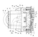
- FIG. 1 is a side view showing a vehicle headlamp according to a first embodiment of the present invention as first to third aspects.
- FIG. FIG. FIG. 2 is a perspective view showing a heat sink and a light source unit.
- FIG. 5 is a cross-sectional view of the lamp unit taken along line VV in FIG. 4.
- 6 is a cross-sectional view of the lamp unit taken along line VI-VI in FIG. 4.
- FIG. FIG. FIG. FIG. 2 is an enlarged view of a portion of the lamp unit in FIG. 1 .
- FIG. 11A and 11B are diagrams illustrating an example of how a holder is fixed to a heat sink. 6 is an enlarged view of a part of FIG.
- FIG. 4 is a diagram showing a light distribution pattern of a low beam in the first embodiment.
- FIG. 4 is a diagram showing a light distribution pattern of a high beam in the first embodiment.
- FIG. 13 is a top view of a lamp unit according to a second embodiment as a fourth aspect.
- FIG. 1 is a side view showing a vehicle headlamp in the first embodiment.
- Vehicle headlamp is generally provided on each of the left and right sides in front of a vehicle.
- “right” means the right side in the forward direction of the vehicle
- “left” means the left side in the forward direction of the vehicle.
- the left and right vehicle headlamp have the same configuration, except that the shapes are roughly symmetrical in the left-right direction. Therefore, one of the vehicle headlamp will be described below.
- the vehicle headlamp 1 of this embodiment mainly comprises a housing 10 and a lamp unit LU.
- the housing 10 is shown in vertical cross section.
- the housing 10 has a lamp housing 11 and a light-transmitting front cover 12.
- the front of the lamp housing 11 is open, and the front cover 12 is fixed to the lamp housing 11 so as to cover the opening.
- the space formed by the lamp housing 11 and the front cover 12 is the lamp chamber R, and the lamp unit LU is housed within this lamp chamber R.
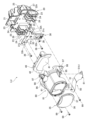
- FIG. 2 is an exploded perspective view of the lamp unit LU, which is an exploded perspective view of the lamp unit LU as seen from diagonally above the front.
- the lamp unit LU of this embodiment mainly comprises a heat sink 20, a light source unit 30, a projection lens 35, an inner lens 40, a shade 50, and a holder 80.
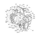
- FIG. 3 is a perspective view showing the heat sink 20 and the light source unit 30.
- the heat sink 20 of this embodiment includes a base plate 21, a plurality of front heat dissipation fins 22a to 22i, a plurality of bosses 23, and a plurality of rear heat dissipation fins 27.
- the base plate 21 is a plate-like member that extends vertically and horizontally, and has three board screw holes 25 provided therein.
- the multiple front heat dissipation fins 22a-22i are plate-shaped members extending forward and up and down from the base plate 21.
- the front heat dissipation fins 22a-22i are formed integrally with the base plate 21, and the number of front heat dissipation fins 22a-22i is nine, but this is not limited to this number.
- the eight front heat dissipation fins 22a-22h are arranged in parallel in the left-right direction, and are lined up from the right in the following order: front heat dissipation fin 22a, front heat dissipation fin 22b, front heat dissipation fin 22c, front heat dissipation fin 22d, front heat dissipation fin 22e, front heat dissipation fin 22f, front heat dissipation fin 22g, and front heat dissipation fin 22h.
- front heat dissipation fins 22c and 22d, the front heat dissipation fins 22d and 22e, and the front heat dissipation fins 22e and 22f are adjacent to each other.
- These four front heat dissipation fins 22c to 22f include a main body portion 220 extending from the base plate 21 and a first extension portion 221 extending forward from the lower side of the main body portion 220.
- the front edge 220e1 of the main body portion 220 of each of the front heat dissipation fins 22c to 22f is generally parallel to the vertical direction, and the distance from the front edge 220e1 to the base plate 21 is generally the same.
- the front edge 221e1 of the first extension portion 221 of each of the front heat dissipation fins 22c to 22f is generally parallel to the vertical direction, and the distance from the front edge 221e1 to the base plate 21 is generally the same.
- the upper edge 221e2 of the first extension 221 of each of the front heat dissipation fins 22c to 22f is inclined downward toward the front and generally overlaps with each other in the left-right direction. Details will be described later, but the main body 220 overlaps with the holder 80 in the front-rear direction behind the holder 80 described below, and the first extension 221 overlaps with the holder 80 below the holder.
- the two adjacent front heat dissipation fins 22d, 22e include a second extension 222 that extends forward from the main body 220 above the first extension 221.
- the front edge 221e1 of the second extension 222 is located rearward of the front edge 221e1 of the first extension 221, and the upper edge 222e2 of the second extension 222 is located below the upper edge 220e2 of the main body 220.
- the front edges of the four front heat dissipation fins 22a, 22b, 22g, and 22h are generally parallel to the vertical direction, and the distance from the front edges to the base plate 21 is generally the same as the distance from the front edge 220e1 of the main body 220 to the base plate 21.
- the bosses 23 are columnar members extending forward from the base plate 21. In this embodiment, the number of bosses 23 is three, but this is not limited to this. Each boss 23 has a holder screw hole 24 formed along the boss 23 from the tip surface 23s. The tip surface 23s is located rearward of the front edge 221e1 of the second extension portion 222, and the distance from the tip surface 23s to the base plate 21 is approximately the same as the distance from the front edge 220e1 of the main body portion 220 to the base plate 21. In this embodiment, each boss 23 is formed integrally with the front heat dissipation fins 22b, 22g, 22i.
- the front heat dissipation fins 22b, 22g, 22i which do not form the first extension portion 221, and the boss 23 are formed integrally.
- the front heat dissipation fins 22b and 22g are provided with positioning pins 26 that extend forward from their front edges and have tapered tips, and the tips of the positioning pins 26 are located forward of the tip surface 23s of the boss 23.
- the multiple rear heat dissipation fins 27 are plate-shaped members that extend rearward and up and down from the base plate 21, are aligned in the left-right direction, and are formed integrally with the base plate 21. There is no limit to the number of multiple rear heat dissipation fins 27.
- the heat sink 20 can be made of a metal such as aluminum.
- the light source unit 30 of this embodiment has three first light sources 31a, 31b, and 31c, a second light source 32, and a circuit board 33.
- the circuit board 33 is placed on the front surface of the base plate 21 of the heat sink 20.
- the circuit board 33 has a through hole 33h at a position corresponding to the board screw hole 25 of the base plate 21, and a screw 36 is inserted into the through hole 33h and fastened to the board screw hole 25, thereby fixing the circuit board 33 to the heat sink 20.
- the first light sources 31a, 31b, 31c and the second light source 32 are mounted on a circuit board 33, and emit white light when power is supplied from the circuit board 33.
- the first light sources 31a, 31b, 31c and the second light source 32 are LEDs (Light Emitting Diodes) and emit light forward.
- the first light source 31a is arranged to the right of the first light source 31b with a gap therebetween, and the first light source 31c is arranged to the left of the first light source 31b with a gap therebetween, and these first light sources 31a, 31b, 31c are lined up in the left-right direction.
- the first light sources 31a, 31b, 31c are light sources for low beam, and emit a first light that forms a light distribution pattern of the low beam.
- the second light source 32 is arranged below the first light sources 31a, 31b, 31c, and the second light source 32 and the first light source 31b are lined up in the approximately vertical direction.
- the second light source 32 is a light source for high beams, and emits second light that forms a high beam light distribution pattern together with the first light. Note that the types and numbers of the first light sources 31a, 31b, and 31c and the second light sources 32 are not limited.
- the first light source 31a, 31b, 31c is located above the front heat dissipation fins 22a-22h arranged in parallel in the left-right direction and below the front heat dissipation fin 22i.
- the first light source 31b and the second light source 32 are located between the front heat dissipation fins 22d and 22e.
- the front heat dissipation fins 22d and 22e closest to the first light source 31b and the second light source 32 on the right and left sides of the first light source 31a and the second light source 32 include the first extension portion 221.
- the first light source 31a is located between the front heat dissipation fins 22c and 22d, and the first light source 31c is located between the front heat dissipation fins 22e and 22f. Additionally, the second light source 32 overlaps with the front heat dissipation fins 22d and 22e in the left-right direction, but does not have to overlap.
- the projection lens 35 of this embodiment has a lens body portion 36 that changes the divergence angle of the light that passes through it, and a flange-shaped fixing portion 37 provided on the outer periphery of the lens body portion 36, and is disposed forward of the light source portion 30.
- the lens body portion 36 is a biconvex aspheric lens whose outer shape is generally an oval track shape that is elongated in the left-right direction.
- the optical axis of the projection lens 35 extends in the front-rear direction and passes between the first light source 31b and the second light source 32. Examples of materials that make up the projection lens 35 include resin, glass, etc.
- the inner lens 40 of this embodiment has a light guide section 41 and a flange-shaped fixing section 42 provided on the outer periphery of the light guide section 41 except for the lower side, and is disposed between the light source section 30 and the projection lens 35.
- FIG. 4 is a front view of the lamp unit LU, which is a front view of the lamp unit LU as seen from the front.
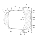
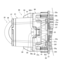
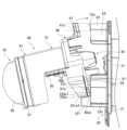
- FIG. 5 is a cross-sectional view of the lamp unit LU taken along line V-V in FIG. 4, which is a horizontal cross-sectional view of the lamp unit LU passing through the first light source 31b and the second light source 32.
- FIG. 6 is a cross-sectional view of the lamp unit LU taken along line VI-VI in FIG. 4, which is a horizontal cross-sectional view of the lamp unit LU passing through the first light sources 31a, 31b, and 31c. Note that part of the heat sink 20 is omitted in FIG. 5, and the heat sink 20 is omitted in FIG. 6.
- the light guide 41 of this embodiment has three first incident surfaces 43a, 43b, and 43c and a second incident surface 43d on the rear side 43.
- the first light from the first light source 31a is incident on the first incident surface 43a
- the first light from the first light source 31b is incident on the first incident surface 43b
- the first light from the first light source 31c is incident on the first incident surface 43c
- the second light from the second light source 32 is incident on the second incident surface 43d.
- the light guide 41 guides the first and second light incident directly or totally to the front side 45.
- the front side 45 emits the first and second light thus guided toward the projection lens 35.
- the front side 45 is curved concavely toward the rear. As shown in FIG.
- a shade 50 which will be described later, is disposed between the front side 45 and the projection lens 35.
- the area above the rear end of the shade 50 on the front side surface 45 is the first emission area 45a that emits the first light
- the area below is the second emission area 45b that emits the second light.
- the light guide 41 guides the first light and the second light in this manner. Therefore, the first light source 31a, 31b, 31c and the inner lens 40 form a first light emission optical system that emits the first light forward, and the second light source 32 and the inner lens 40 form a second light emission optical system that emits the second light forward.
- the first light emission optical system and the second light emission optical system share the inner lens 40.
- the optical axis L1C of the first light emitted from the first light emission optical system is inclined downward toward the front
- the optical axis L2C of the second light emitted from the second light emission optical system is inclined upward toward the front.
- the front side 46 of the fixing part 42 is connected to the front side 45 of the light guide part 41. Therefore, the surface of the inner lens 40 facing the projection lens 35 is a surface made up of these front sides 45, 46, and the upper and left and right sides of the outer periphery of this surface are the outer periphery 46e of the front side 46, and the lower side is the lower edge 45e of the front side 45.
- the rear side 47 of the fixing part 42 is connected to the rear side 43 of the light guide part 41.
- the surface of the inner lens 40 opposite the projection lens 35 is a surface made up of these rear sides 43, 47, and the upper and left and right sides of the outer periphery of this surface are the outer periphery 47e of the rear side 47, and the lower side is the lower edge 43e of the rear side 43.
- the front side 46 and the rear side 47 are flat surfaces roughly parallel to the vertical direction, and the front side 46 is located closest to the projection lens 35.
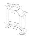
- FIG. 7 is an exploded perspective view of the shade 50, as viewed from diagonally above the front.
- the shade 50 of this embodiment is a plate-like member, and is made up of a main part 51 and a reinforcing part 61.
- the main part 51 and the reinforcing part 61 are flat plate-like members with one main surface being the upper surface, and are long in the left-right direction.
- the reinforcing part 61 is superimposed on the main part 51 from below.
- the main part 51 has a pair of left and right fixing parts 52, 52 and a base part 53. Note that FIG. 7 shows a dotted line indicating the boundary between the left fixing part 52 and the base part 53.
- the pair of fixing parts 52, 52 extend horizontally and have two through holes 51h1, 51h2 penetrating in the thickness direction.
- the through hole 51h2 is located rearward of the through hole 51h2.
- the through holes 51h1, 51h2 in the right fixing part 52 are generally circular, and the through holes 51h1, 51h2 in the left fixing part 52 are generally oval track shaped and elongated in the left-right direction.
- the pair of fixing parts 52, 52 are located on the same plane, but one fixing part 52 may be located higher than the other fixing part 52.
- the base portion 53 is long in the left-right direction and is located between a pair of fixing portions 52, 52 and is sandwiched in the left-right direction by the pair of fixing portions 52, 52, with its left end connected to the left fixing portion 52 and its right end connected to the right fixing portion 52.
- the left-right central portion of the front end 53e1 of the base portion 53 is curved in an arc that is concave toward the rear, and both left-right ends of the front end 53e1 are located on the same straight line extending in the left-right direction.
- the rear end 53e2 of the base portion 53 is curved in an arc that is convex toward the rear.
- the upper surface 51S1 of the main portion 51 is the upper surface of the shade 50, and has a first step portion 55a and a second step portion 55b. These step portions 55a, 55b are formed by bending the base portion 53. Therefore, the step portions 55a, 55b are located in the area of the upper surface 51S1 that becomes the upper surface of the base portion 53. In addition, the area of the upper surface 51S1 other than these step portions 55a, 55b is a flat surface that extends generally horizontally.
- the first step portion 55a is located near the center of the base portion 53 in the left-right direction and extends linearly in the front-rear direction. Although not illustrated, the first step portion 55a is aligned with the optical axis L1C in a plan view.
- the second step portion 55b is generally parallel to the first step portion 55a and extends along the right edge of the base portion 53.
- the heights of the steps 55a and 55b are constant in the direction in which the steps 55a and 55b extend, and are the same as each other.
- the front ends of the steps 55a and 55b are connected to the front end 53e1 of the base portion 53, and the rear ends are connected to the rear end 53e2 of the base portion 53.
- the first step 55a is formed by an inclined surface that slopes downward from the right side to the left side
- the second step 55b is formed by a surface that extends in a generally vertical direction.
- the region between the first step 55a and the second step 55b on the upper surface 51S1 is higher than the other regions.
- the region between the first step 55a and the second step 55b may be lower than the other regions.
- the first step 55a may be formed by a surface that extends in a generally vertical direction
- the second step 55b may be formed by an inclined surface that slopes with respect to the vertical direction.
- a protrusion 56 is provided on the upper surface 51S1 of the main part 51, located between the first step portion 55a and the second step portion 55b. In a plan view, the protrusion 56 does not overlap with the reinforcing portion 61 described below.
- the protrusion 56 is a hemispherical shape that protrudes upward, and is formed by curving the main part 51. The position of the protrusion 56 is not limited, and the protrusion 56 does not have to be provided on the upper surface 51S1.
- the material forming the main part 51 may be, for example, a metal plate or a plated metal plate, and examples of metals include stainless steel and carbon steel.
- the thickness of the main part 51 is, for example, 0.05 mm to 1.0 mm.
- the reinforcing portion 61 of this embodiment has a pair of left and right mounting portions 62 and a connection portion 63.
- the upper surface 61S1 of the reinforcing portion 61 faces the lower surface of the main portion 51, and the reinforcing portion 61 is overlapped on the main portion 51 from below.
- the right mounting portion 62 overlaps only with the right fixing portion 52, and the left mounting portion 62 overlaps only with the left fixing portion 52.
- the fixing portions 52 and mounting portions 62 that overlap each other have roughly the same shape.
- each mounting portion 62 has through holes 61h1, 61h2 that overlap with the through holes 51h1, 51h2 of the fixing portion 52, respectively.
- each mounting portion 62 is fixed to the fixing portion 52 by, for example, laser welding.
- connection portion 63 extends from one mounting portion 62 to the other mounting portion 62, and at least a portion of it overlaps with the base portion 53.
- the right end of the connection portion 63 connects to the rear side of the left end of the right mounting portion 62
- the left end of the connection portion 63 connects to the rear side of the right end of the left mounting portion 62.
- the connection portion 63 also runs along the area to the left of the first step portion 55a in the base portion 53 of the main portion 51, and is fixed to the base portion 53 by, for example, laser welding.
- the base part 53 includes a part that includes the front end of the main part 51 and does not overlap with the reinforcing part 61, and a part that overlaps with the reinforcing part 61 and to which the reinforcing part 61 is fixed.
- the part of the front end 63e1 of the connecting part 63 that is located rearward of the front end 53e1 of the base part 53 is curved in an arc that is concave backward, and the distance between the part and the front end 53e1 is maintained at a predetermined value or more in the left-right direction.
- the rear end 63e2 of the connecting part 63 coincides with the rear end 53e2 of the base part 53. Note that the rear end 63e2 and the rear end 53e2 do not have to coincide.
- the material forming the reinforcing portion 61 may be the same as that of the main portion 51, and the thickness of the reinforcing portion 61 is, for example, 0.05 mm to 1.0 mm.
- the reinforcing portion 61 is thicker than the main portion 51, but the thickness of the reinforcing portion 61 may be equal to or less than the thickness of the main portion 51.
- the Young's modulus of the reinforcing portion 61 is higher than that of the main portion 51, but the Young's modulus of the reinforcing portion 61 may be equal to or less than that of the main portion 51.
- the shade 50 is disposed between the projection lens 35 and the inner lens 40.
- the shade 50 crosses the front side surface 45 of the light guide portion 41.
- the optical axis of the projection lens 35 passes through or near the first step portion 55a, and the rear focal point of the projection lens 35 is located at or near the front end 53e1 of the base portion 53.
- the shade 50 and the inner lens 40 are spaced apart. The gap between the shade 50 and the inner lens 40 is wider than the gap between the shade 50 and the projection lens 35.
- FIG. 8 is a perspective view of the holder 80, as viewed from diagonally above the front.
- the holder 80 of this embodiment has a lens holding portion 81, a first protective portion 91, and a second protective portion 96, and holds the projection lens 35, the inner lens 40, and the shade 50.
- the holder 80 can be made of a material such as a resin, such as opaque polycarbonate, and in this embodiment, the lens holding portion 81, the first protective portion 91, and the second protective portion 96 are integrally formed.
- the lens holding portion 81 in this embodiment is a cylindrical member extending in the front-rear direction, and has a lower plate portion 82, side plate portions 83 connected to both left and right edges of the lower plate portion 82, and an upper plate portion 84 facing the lower plate portion 82 and connected to each of the side plate portions 83.
- the outer shape of the lens holding portion 81 is matched to the outer shape of the lens main body portion 36 of the projection lens 35, with the lower plate portion 82 and upper plate portion 84 extending generally horizontally, and the side plate portion 83 extending vertically and curved in an arc so as to be convex outward.
- the rear edge 82e of the lower plate portion 82 is located forward of the rear edge 83e of the side plate portion 83.
- Behind the rear edge 82e is a space sandwiched between the left and right side plate portions 83, and no other members are placed in this space.
- a flange-shaped protrusion 85 protruding from the inner peripheral surface is provided at the front end of the lens holding portion 81, and the protrusion 85 widens the width of the front end face of the lens holding portion 81.
- a plurality of pedestal portions 86 protruding forward are provided at the front end face of the lens holding portion 81. As shown in FIG.
- the fixing portion 37 of the projection lens 35 abuts against the pedestal portion 86 from the front side, and the fixing portion 37 is fixed to the pedestal portion 86 by, for example, ultrasonic welding or laser welding, and the projection lens 35 is supported by the holder 80.
- the lower plate portion 82, the side plate portion 83, and the upper plate portion 84 extend from the light source portion 30 side toward the projection lens 35 side, and the rear edges 82e, 83e are edges on the light source portion 30 side.
- the rear edge 82e is located forward of the rear edge 83e.
- the lower plate portion 82 is not formed in the range from the first position on the projection lens 35 side of the rear edge 83e, which is the edge of the side plate portion 83 on the light source unit 30 side, to the rear edge 83e on the light source unit 30 side.
- the first protective part 91 of this embodiment is a semi-cylindrical member extending in the front-rear direction, and has an upper plate part 94 and side plate parts 93 connected to both left and right edges of the upper plate part 94.
- the outer shape of the first protective part 91 is matched to the outer shape of the upper half of the lens holding part 81, and the upper plate part 94 extends rearward from the rear end of the upper plate part 84, and the side plate part 93 extends rearward from the upper part at the rear end of the side plate part 83.
- the member consisting of the lens holding part 81 and the first protective part 91 is a cylindrical member matched to the outer shape of the lens main body part 36 of the projection lens 35, and a predetermined range of the lower side from the rear end toward the front is cut out.
- the rear end part of the first protective part 91 is provided with a flange-shaped connecting plate part 92 that protrudes outward in a generally vertical direction.
- the lower end part of each side plate part 93 is provided with a support plate 95 that extends outward in a generally horizontal direction. As shown in Fig. 2 and Fig.
- each of the pair of left and right fixing parts 52 of the main part 51 of the shade 50 abuts against the support plate 95 from below, and is fixed to the support plate 95 together with the mounting part 62 of the reinforcing part 61 overlapping the fixing part 52.
- the fixing part 52 and the mounting part 62 are fixed to the support plate 95 by thermal caulking. Specifically, the tip of the pin protruding downward from the support plate 95 and penetrating the through hole 51h1 of the fixing part 52 and the through hole 61h1 of the mounting part 62 is melted by heat to form a head 95a that closes the opening of the through hole 61h1 on the opposite side to the support plate 95 side.
- the fixing part 52 and the mounting part 62 are sandwiched between the support plate 95 and the head 95a, the fixing part 52 and the mounting part 62 are fixed to the support plate 95, and the shade 50 is held by the holder 80.
- the base portion 53 of the shade 50 is covered from above with the first protective portion 91 at a predetermined distance, protecting the base portion 53.
- the method for fixing the shade 50 is not limited, and it may be fixed by laser welding, for example.
- the second protective part 96 is a cylindrical member located behind the first protective part 91 and extending in the front-rear direction.
- the upper part of the second protective part 96 is located outward from the first protective part 91, and the front end part of this part is connected to the connecting plate part 92.
- a part of the inner lens 40 is housed in the internal space of the second protective part 96, and the inner lens 40 is protected.
- the rear side of the connecting plate part 92 is provided with a plurality of pedestal parts (not shown) that protrude toward the rear, and the fixing part 42 of the inner lens 40 abuts against these pedestal parts from the rear side and is fixed to these pedestal parts by, for example, ultrasonic welding or laser welding. In this manner, the inner lens 40 is held by the holder 80.
- three fixing plates 97 extending generally vertically outward are provided on the upper side and both left and right sides of the rear end of the second protective section 96.
- the fixing plates 97 correspond to the bosses 23 of the heat sink 20, and the fixing plates 97 are provided with through holes 98a corresponding to the holder screw holes 24 of the bosses 23.
- the fixing plates 97 on both the left and right sides are provided with through holes 98b corresponding to the positioning pins 26, and the upper fixing plate 97 is provided with a protrusion 97p protruding toward the rear.
- the protrusion 97p is generally C-shaped and surrounds the upper side and both left and right sides of the through hole 98a at a distance from the edge of the through hole 98a.
- the positioning of the holder 80 relative to the heat sink 20 is determined by inserting the positioning pins 26 into the through holes 98b.
- the holder 80 is fixed to the heat sink 20 by the fixing plate 97 abutting against the tip surface 23s of the boss 23 from the front side, and the screw 99 is inserted into the through hole 98a and fastened to the holder screw hole 24.
- the holder fixing portion that fixes the holder 80 to the heat sink 20 is the tip surface 23s of the boss 23.
- the fixed portion that is fixed to the tip surface 23s of the holder 80 is the peripheral portion 97a that surrounds the through hole 98a along the edge of the through hole 98a in the fixing plate 97, and the peripheral portion 97a is shown by a dashed line in FIG. 8.
- the lower surface of the second protective portion 96 and the lower side surfaces of the fixing plates 97 on both the left and right sides are located on the same plane, and these surfaces are part of the lower surface of the holder 80.
- the holder 80 also has an upper opening 80h1 that opens upward.
- the upper opening 80h1 is a single through hole that is provided across the upper plate portion 94, the connecting plate portion 92, and the second protective portion 96 of the first protective portion 91.
- FIG. 9 is a top view of the lamp unit LU, and is a view of the lamp unit LU viewed from above along the vertical direction. Note that a part of the heat sink 20 is omitted in FIG. 9.
- the inner lens 40 is exposed vertically upward from the upper opening 80h1.
- the outer peripheral edge 46e of the front side surface 46 at the fixing portion 42 of the inner lens 40 is exposed vertically upward from the upper opening 80h1.
- the outer peripheral edge 46e of the front side surface 46 is the outer peripheral edge of the surface of the inner lens 40 facing the projection lens 35, and therefore the outer peripheral edge is exposed vertically upward from the upper opening 80h1.
- the outer peripheral edge 47e of the rear side surface 47 of the fixing portion 42 of the inner lens 40 is exposed vertically upward from the upper opening 80h1.
- the outer peripheral edge 47e of the rear side surface 47 is the outer peripheral edge of the surface of the inner lens 40 opposite the projection lens 35 side, so this outer peripheral edge is exposed vertically upward from the upper opening 80h1.
- the shade 50 is exposed vertically upward from the upper opening 80h1.
- the holder 80 is fixed to the tip surface 23s of the boss 23 of the heat sink 20. Therefore, the holder 80 is spaced apart from the base plate 21 of the heat sink 20, and the holder 80 is disposed in front of the first light sources 31a to 31c and the second light source 32.
- the inner lens 40 is also spaced apart from the light source unit 30. In this embodiment, the gap between the inner lens 40 and the light source unit 30 is exposed vertically upward and vertically downward.
- the exposed gaps include the gap between the inner lens 40 and the first light source 31a and the gap between the inner lens 40 and the first light source 31c.
- the holder 80 has a semi-cylindrical first protective portion 91 positioned between the cylindrical lens holding portion 81 and the second protective portion 96. Therefore, as shown in FIG. 5, a lower opening 80h2 that opens downward is formed below the first protective portion 91 in the holder 80.
- the upper opening 80h1 overlaps with the lower opening 80h2 in the up-down direction.
- the inner lens 40 and the shade 50 are exposed vertically downward from the lower opening 80h2.
- the front end 53e1 of the base portion 53 which is the front end of the shade 50
- the lower edge 45e of the front side surface 45 which is the lower edge of the front side surface of the inner lens 40
- the gap between the shade 50 and the inner lens 40 are exposed vertically downward from the lower opening 80h2.
- a portion of the edge of this lower opening 80h2 is defined by the rear edge 82e of the lower plate portion 82 of the lens holding portion 81.
- the lower end portion of the cylindrical second protective portion 96 can be considered to be part of the lower plate portion 82, with the rear edge 82e located forward of the rear edge 83e of the side plate portion 83, and the lower end portion of the second protective portion 96 located forward of the rear edge 83e.
- the lower plate portion 82 is not formed in the range from a first position P1 on the projection lens 35 side of the rear edge 83e of the side plate portion 83 to a second position P2 on the light source unit 30 side of the rear edge 83e, and it can be understood that the lower opening 80h2 is formed as a result.
- the rear edge 82e is located at the first position P1, and the front end 96de of the lower end of the second protective portion 96 is located at the second position P2.
- the first position P1 is indicated by a dotted line
- the second position P2 is indicated by a two-dot chain line
- a line along the rear edge 83e of the side plate portion 83 is indicated by a dashed line.
- the inner lens 40 is located closer to the light source unit 30 than the first position P1. At least a portion of the shade 50 is located closer to the light source unit 30 than the first position P1, and in this embodiment, the shade 50 is located between the first position P1 and the second position P2.
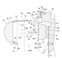
- FIG. 10 is an enlarged view of a portion of the lamp unit LU in FIG. 1, showing an enlarged view of the vicinity of the base plate 21 of the heat sink 20.
- FIG. 11 is a bottom view of the lamp unit LU, showing the lamp unit LU from below along the vertical direction.
- the main body 220 of the front heat dissipation fins 22c to 22f overlaps with the holder 80 in the front-to-rear direction behind the holder 80, and the first extension 221 overlaps with the holder 80 below the holder 80.
- the second extension 222 of the front heat dissipation fins 22d, 22e extends into the internal space of the second protective portion 96 of the holder 80, and the lower portion of the second protective portion 96 is sandwiched between the first extension 221 and the second extension 222 while being spaced apart from the first extension 221 and the second extension 222.
- the second protective portion 96 is a cylindrical member extending in the front-rear direction. Therefore, the lower portion of the second protective portion 96 can be understood as a plate-like portion extending in the front-rear direction and sandwiched between the first extension portion 221 and the second extension portion 222.
- the second protective portion 96 may be in contact with at least one of the first extension portion 221 and the second extension portion 222.
- the inner lens 40 is disposed above the second extension portion 222.
- the inner lens 40 is located above the front heat dissipation fins 22c to 22f and overlaps with these front heat dissipation fins 22c to 22f.
- the front heat dissipation fins 22a, 22b, 22g, 22h, and 22i overlap with the holder 80 in the front-rear direction behind the holder 80.
- the holder 80 may include a front heat dissipation fin that does not overlap with the holder 80 in the front-rear direction behind the holder 80.
- FIG. 12 is a diagram showing an example of how the holder 80 is fixed to the heat sink 20.
- the upper edge 221e2 of the first extension portion 221 in the front heat dissipation fins 22c to 22f is abutted against a surface 80ds consisting of the lower surface of the second protective portion 96, which is the lower surface of the holder 80, and the lower side surfaces of the fixing plates 97 on both the left and right sides.
- the rear edge of the surface 80ds is abutted against the connection portion 220c between the upper edge 221e2 of the first extension portion 221 and the front edge 220e1 of the main body portion 220.
- the tip surface 23s of the boss 23 as the holder fixing portion and the peripheral portion 97a as the fixed portion fixed to the tip surface 23s overlap in the front-rear direction. Therefore, in this embodiment, by achieving the above state, the holder 80 is positioned relative to the heat sink 20 in the up-down direction. In addition, in the above state, the surface 80ds of the holder 80 abuts against the upper edge 221e2 of the first extension portion 221, so that the holder 80 is supported by the first extension portion 221. This makes it easy to position the holder 80 relative to the heat sink 20 in the vertical direction, and makes it easy to fix the holder 80 to the heat sink 20. In FIG.
- the peripheral portion 97a is shown by hatching, and straight lines extending horizontally and forward from the upper and lower edges of the tip surface 23s are shown by dashed lines.
- the position of the center of the peripheral portion 97a in the left-right direction is the same as the position of the center of the tip surface 23s in the left-right direction
- the position of the center of the through hole 98a is the same as the position of the center of the holder screw hole 24.
- the tip of the positioning pin 26 is inserted into the through hole 98b of the fixing plate 97. Therefore, in the above state, the left-right movement of the holder 80 is restricted. In the above state, the tip of the positioning pin 26 does not have to be inserted into the through hole 98b of the fixing plate 97.
- the holder 80 is rotated rearward to abut the rear surface of the fixing plate 97 against the tip surface 23s of the boss 23, and the screw 99 is fastened into the holder screw hole 24. In this manner, the holder 80 is fixed to the heat sink 20.
- the tip of the upper boss 23 is surrounded by the protrusion 97p provided on the upper fixing plate 97.
- the tip of the positioning pin 26 is inserted into the through hole 98b of the fixing plate 97 in the above state, the left-right movement of the holder 80 when the holder 80 is rotated rearward is restricted. This makes it easier to fix the holder 80 to the heat sink 20.
- FIG. 13 is an enlarged view of a portion of FIG. 5, showing an example of the optical paths of the first light emitted from the first light source and the second light emitted from the second light source. Note that the reflection angle and refraction angle of the light shown in FIG. 13 may not be accurate.
- the first light L1 is emitted from the first light source 31a, 31b, 31c.
- the first light L1 enters the light guide section 41 of the inner lens 40 from the first entrance surface 43a, 43b, 43c, and is emitted toward the projection lens 35 from the first emission area 45a of the front side surface 45 of the light guide section 41.
- Most of the first light L1 emitted from the first emission area 45a passes above the shade 50 and directly enters the projection lens 35.
- a portion of the first light L1 emitted from the first emission area 45a is irradiated onto the upper surface 51S1 of the main section 51 of the shade 50.
- the upper surface of the base section 53 which is a part of the upper surface 51S1, reflects a portion of the first light L1 toward the projection lens 35 so that a cutoff line having a shape corresponding to the front end 53e1 is formed in the light distribution pattern formed by the first light L1, and the light distribution pattern becomes a low beam light distribution pattern. Then, the reflected first light L1 and the first light L1 directly incident on the projection lens 35 from the first emission region 45a form a low beam light distribution pattern. That is, the shade 50 forms a cutoff line.
- the protrusion 56 is located in the region on the upper surface 51S1 where the first light L1 is irradiated.
- the protrusion 56 reflects and blocks another part of the first light L1 so that it does not enter the projection lens 35. Therefore, a predetermined region in the low beam light distribution pattern can be darkened.
- the first light L1 is also irradiated to the region between the front end 53e1 and the protrusion 56 on the upper surface 51S1, and the region becomes bright. Therefore, a gap can be formed between the predetermined darkened region and the cutoff line.
- the low beam light distribution pattern is formed by the first light L1, and the light having this low beam light distribution pattern passes through the projection lens 35 and is emitted from the vehicle headlamp 1.
- the rear focal point of the projection lens 35 is located at or near the front end 53e1. Therefore, the low beam light distribution pattern projected in front of the vehicle is a light distribution pattern that is inverted by the projection lens 35.
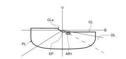
- FIG. 14 is a diagram showing the low beam light distribution pattern in this embodiment.
- S indicates a horizontal line
- V indicates a vertical line passing through the center of the vehicle in the left-right direction
- the low beam light distribution pattern PL projected on a virtual vertical screen located 25 m ahead of the vehicle is shown by a thick line.
- the light guide 41 and the shade 50 are shaped so that the light distribution pattern of the first light L1 becomes this low beam light distribution pattern PL.
- the low beam light distribution pattern PL of this embodiment is for countries and regions where vehicles drive on the left side of the road.
- the cutoff line CL of the low beam light distribution pattern PL corresponds to the shape of the front end 53e1 of the base 53, and the cutoff line CL has a step portion CLa corresponding to the first step portion 55a.
- the step portion CLa consists of a line that slopes upward toward the left side from the elbow point EP located below the horizontal line S and on or near the vertical line V.
- area AR1 in the low beam light distribution pattern PL is darker than the surrounding area. Area AR1 is located on the oncoming lane OL side of elbow point EP. Therefore, area AR1 may overlap with the road surface between the vehicle and an oncoming vehicle, and glare caused by light reflected on the road surface to the driver of the oncoming vehicle may be reduced.
- the position and shape of area AR1 can be changed by adjusting the position and shape of protrusion 56. Also, by not providing protrusion 56 on upper surface 51S1, area AR1 can be prevented from being darkened.
- the first light L1 is emitted from the first light source 31a, 31b, 31c, and the second light L2 is emitted from the second light source 32. Therefore, as described above, the low beam light distribution pattern PL is formed by the first light L1, and light having the low beam light distribution pattern PL is emitted from the vehicle headlamp 1.
- the second light L2 emitted from the second light source 32 enters the light guide 41 from the second entrance surface 43d and exits from the second exit area 45b of the front side surface 45 toward the projection lens 35. Most of the second light L2 emitted from the second exit area 45b passes under the shade 50 and enters the projection lens 35 directly.
- a part of the second light L2 emitted from the second exit area 45b is irradiated to a portion of the lower surface 51S2 of the main part 51 of the shade 50 that is exposed to the outside.
- the part of the lower surface 51S2 exposed to the outside is a part of the lower surface of the base portion 53.
- This part of the lower surface 51S2 reflects a part of the second light L2 toward the projection lens 35 so that a cutoff line having a shape corresponding to the front end 53e1 is formed in the light distribution pattern formed by the second light L2, and the light distribution pattern becomes an additional light distribution pattern.
- the additional light distribution pattern is formed by the reflected second light L2 and the second light L2 directly incident on the projection lens 35 from the second emission area 45b.
- the additional light distribution pattern is a light distribution pattern that is added to the low beam light distribution pattern PL to form a high beam light distribution pattern. Therefore, the second light L2 forms a high beam light distribution pattern together with the first light L1. In this way, the additional light distribution pattern is formed by the second light L2, and the light having the additional light distribution pattern passes through the projection lens 35 and is emitted from the vehicle headlamp 1. Therefore, the light having the high beam light distribution pattern is emitted from the vehicle headlamp 1.
- the additional light distribution pattern projected forward of the vehicle is a light distribution pattern that is inverted by the projection lens 35, similar to the low beam light distribution pattern PL.
- the cutoff line of the additional light distribution pattern is determined by the front end 53e1 of the base portion 53, similar to the cutoff line CL of the low beam light distribution pattern PL. Therefore, the cutoff line of the additional light distribution pattern and the cutoff line CL of the low beam light distribution pattern PL roughly coincide with each other, and the high beam light distribution pattern is a combination of the additional light distribution pattern and the low beam light distribution pattern PL.
- the vehicle headlamp 1 of this embodiment can switch between emitting low beam and emitting high beam by switching between emitting and not emitting light from the second light source 32.
- FIG. 15 is a diagram showing the high beam light distribution pattern in this embodiment, and is a diagram showing the high beam light distribution pattern in the same way as FIG. 14.
- the cutoff line CL in the low beam light distribution pattern PL is shown by a dotted line.
- the area below the cutoff line CL in the high beam light distribution pattern PH is formed by the first light L1
- the area above the cutoff line CL is formed by the second light L2.
- the vehicle headlamp 1 of this embodiment as a first aspect includes a circuit board 33 on which the first light source 31a, 31b, 31c and the second light source 32 are mounted, a projection lens 35, a holder 80 that holds the projection lens 35, and a heat sink 20.
- the holder 80 is disposed in front of the first light source 31a, 31b, 31c and the second light source 32, and the heat sink 20 includes a base plate 21 that extends vertically and horizontally and has the circuit board 33 disposed on its front surface, and a plurality of front heat dissipation fins 22a to 22i that extend forward and vertically from the base plate 21.
- the four front heat dissipation fins 22c to 22f include a main body portion 220 that extends from the base plate 21 and overlaps with the holder 80 in the front-rear direction behind the holder 80, and a first extension portion 221.
- the first extension portion 221 extends forward from the lower side of the main body portion 220 and overlaps with the holder 80 below the holder 80. Therefore, the front heat dissipation fins 22c to 22f are expanded by the amount of the first extension portion 221 compared to the case where the first extension portion 221 is not formed, and the heat dissipation effect is improved.
- the main body portion 220 and the first extension portion 221 extend vertically, and the first extension portion 221 overlaps with the holder 80 below the holder 80.
- the vehicle headlamp 1 of the present embodiment compared to the case where the first extension portion 221 overlaps with the holder 80 above the holder 80, the air flow toward the first extension portion 221 below the first extension portion 221 can be suppressed from being disturbed by the holder 80 among the air flows of air directed upward due to the heat of the first light sources 31a, 31b, 31c and the second light source 32. Therefore, according to the vehicle headlamp 1 of this embodiment as the first aspect, compared to the above case, it is possible to suppress turbulence of the air flow along the first extension portion 221, and improve the heat dissipation effect of the first extension portion 221.
- the two front heat dissipation fins 22d, 22e include a second extension portion 222.
- the second extension portion 222 extends forward from the main body portion 220 above the first extension portion 221, and the holder 80 includes a cylindrical second protective portion 96 extending in the front-rear direction, and a lower portion of the second protective portion 96 extends in the front-rear direction and is sandwiched between the first extension portion 221 and the second extension portion 222.
- the vehicle headlamp 1 of this embodiment when the holder 80 is positioned, the vertical movement of the holder 80 relative to the heat sink 20 can be restricted by the first extension portion 221 and the second extension portion 222, making it easier to position the holder 80.
- the holder 80 only needs to include a plate-like portion that extends in the front-rear direction and is sandwiched between the first extension portion 221 and the second extension portion 222, and the plate-like portion may be located in a portion other than the lower portion of the second protection portion 96.
- the vehicle headlamp 1 of this embodiment as the first aspect includes an inner lens 40 through which light emitted from the first light source 31a, 31b, 31c and the second light source 32 passes, and the inner lens 40 is disposed above the second extension portion 222.
- the upper edge 222e2 of the second extension portion 222 is located below the upper edge 220e2 of the main body portion 220 of the front heat dissipation fins 22d, 22e including the second extension portion 222.
- the vehicle headlamp 1 of this embodiment as the first aspect, it is possible to prevent the second extension portion 222 from approaching too close to the inner lens 40, and to prevent the inner lens 40 from heating up, compared to when the upper edge 222e2 of the second extension portion 222 is located at the same height as the upper edge 220e2 of the main body portion 220 of the front heat dissipation fins 22d, 22e including the second extension portion 222.
- the upper edge 222e2 of the second extension 222 may be located at the same height as the upper edge 220e2 of the main body 220 of the front heat dissipation fins 22d, 22e that include the second extension 222, or may be located above this upper edge 220e2.
- the front heat dissipation fins 22a to 22h are arranged in parallel in the left-right direction.
- the front heat dissipation fins 22d, 22e closest to the first light source 31b and the second light source 32 on the right and left sides of the first light source 31b and the second light source 32 respectively include the first extension portion 221.
- the first light source 31b and the second light source 32 are positioned between the front heat dissipation fins 22d, 22e which include the first extension portion 221. Therefore, according to the vehicle headlamp 1 of this embodiment as the first aspect, it is possible to easily dissipate heat generated by the first light source 31b and the second light source 32.
- first extension portion 221 can block a portion of the light from the first light source 31b and the second light source 32 that leaks out between the front heat dissipation fins 22d, 22e and the holder 80, thereby preventing the light from the first light source 31b and the second light source 32 from becoming stray light.
- the front heat dissipation fins 22c to 22f include the first extension portion 221 as described above, and these front heat dissipation fins 22c to 22f are adjacent to each other. Therefore, according to the vehicle headlamp 1 of the present embodiment as the first aspect, it is possible to make the first extension portion 221 of the front heat dissipation fins easier to see when, for example, placing the holder 80, compared to a case in which the front heat dissipation fins including the first extension portion 221 are not adjacent.
- the vehicle headlamp 1 of the present embodiment as the first aspect, it is possible to make it easier to prevent the holder 80 from unintentionally abutting the first extension portion 221 when placing the holder 80.
- the front heat dissipation fins including the first extension portion 221 do not have to be adjacent.
- the vehicle headlamp 1 of this embodiment as the second aspect includes a light source unit 30, a projection lens 35, and a holder 80 that holds the projection lens 35.
- the holder 80 has a lower plate portion 82 that extends from the light source unit 30 side toward the projection lens 35 side, and a pair of side plate portions 83 that extend from the light source unit 30 side toward the projection lens 35 side and are connected to both left and right edges of the lower plate portion 82.
- sunlight incident from the projection lens tends to be concentrated in the lower part of the holder.
- the lower plate portion 82 of the holder 80 is not formed in the range from a first position P1 on the projection lens 35 side of a rear edge 83e, which is the edge of the side plate portion 83 on the light source unit 30 side, to a second position P2 on the light source unit 30 side of the rear edge 83e.
- the vehicle headlamp 1 of this embodiment compared to when the lower plate portion 82 is formed in the range from the first position P1 to the second position P2 described above, sunlight entering from the outside through the projection lens 35 can be diffused into the space below the lower plate portion 82 without being concentrated by the lower plate portion 82, and overheating of the holder 80 due to sunlight can be suppressed.
- the vehicle headlamp 1 of this embodiment as a second aspect further includes an inner lens 40 that is disposed between the light source unit 30 and the projection lens 35 and through which the light emitted from the light source unit 30 passes. As shown in FIG. 5, the inner lens 40 is located closer to the light source unit 30 than the first position P1. Therefore, according to the vehicle headlamp 1 of this embodiment as a second aspect, it is possible to prevent sunlight entering from the projection lens 35 from entering the inner lens 40 and concentrating at an unintended position, compared to when the inner lens 40 is located closer to the projection lens 35 than the first position P1. Note that the inner lens 40 may be located closer to the projection lens 35 than the first position P1.
- the vehicle headlamp 1 of the present embodiment as the second aspect further includes a shade 50 disposed between the inner lens 40 and the projection lens 35, and the shade 50 forms a cutoff line CL of the low beam light distribution pattern PL. Therefore, the vehicle headlamp 1 of the present embodiment as the second aspect can emit a low beam even if the first light L1 emitted from the light source unit 30 does not have a low beam light distribution pattern, so the configuration of the light source unit 30 can be simplified. Also, as shown in FIG. 5, in the vehicle headlamp 1 of the present embodiment as the second aspect, at least a part of the shade 50 is located closer to the light source unit 30 than the first position P1.
- the vehicle headlamp 1 of the present embodiment compared to the case where the entire shade 50 is located closer to the projection lens 35 than the first position P1, it is possible to suppress the sunlight entering from the projection lens 35 from being reflected by the shade 50 and being concentrated at an unintended position.
- the shade 50 may be located closer to the projection lens 35 than the first position P1.
- the shade 50 When the shade 50 is heated by the light from the light source unit 30, an ascending air current is generated around the shade 50.
- the shade 50 In the vehicle headlamp 1 of the present embodiment as the second aspect, the shade 50 is located between the first position P1 and the second position P2. Therefore, according to the vehicle headlamp 1 of the present embodiment as the second aspect, it is possible to make it easier for the air below the lower plate portion 82 of the holder 80 to flow near at least one of the front end 53e1, which is the end of the shade 50 on the projection lens 35 side, and the rear end, which is the end on the light source unit 30 side. Therefore, according to the vehicle headlamp 1 of the present embodiment as the second aspect, it is possible to prevent the heated air from remaining around the shade 50, and to prevent the shade 50 from being overheated. Note that at least a part of the shade 50 does not have to be located between the first position P1 and the second position P2.
- the inner lens 40 and the shade 50 are spaced apart. Therefore, according to the vehicle headlamp 1 of this embodiment as the second aspect, the transfer of heat from the shade 50 to the inner lens 40 can be suppressed.
- the holder 80 is formed with an upper opening 80h1 through which the inner lens 40 and the shade 50 are exposed upward. Therefore, according to the vehicle headlamp 1 of this embodiment as the second aspect, the air below the lower plate portion 82 of the holder 80 can pass around the inner lens 40 and the shade 50 toward the upper opening 80h1, and the heat of the inner lens 40 and the shade 50 can be released to the outside from the upper opening 80h1.
- the vehicle headlamp 1 of the present embodiment as the third aspect includes a light source unit 30, an inner lens 40, a projection lens 35, and a holder 80.
- the holder 80 holds the projection lens 35 and houses a part of the inner lens 40, and an upper opening 80h1 is formed in the holder 80 through which the inner lens 40 is exposed upward. Therefore, according to the vehicle headlamp 1 of the present embodiment as the third aspect, compared to the case where the upper opening 80h1 is not formed, the heat of the inner lens 40 heated by the light from the light source unit 30 can be released to the outside from the upper opening 80h1, and the heat can be prevented from being trapped in the internal space of the holder 80 that houses the inner lens 40. Therefore, according to the vehicle headlamp 1 of the present embodiment as the third aspect, overheating can be prevented compared to the above case.
- the outer peripheral edge 46e of the front side surface 46 which is the outer peripheral edge of the surface of the inner lens 40 facing the projection lens 35, is exposed upward from the upper opening 80h1. Therefore, according to the vehicle headlamp 1 of this embodiment as the third aspect, an air flow can be formed that runs along the front sides 45, 46, which are the surfaces of the inner lens 40 facing the projection lens 35, toward the upper opening 80h1, making it easier to release heat from the inner lens 40 to the outside through the upper opening 80h1. Note that the outer peripheral edge of the surface of the inner lens 40 facing the projection lens 35 does not have to be exposed from the upper opening 80h1.
- the outer peripheral edge 47e of the rear side surface 47 which is the outer peripheral edge of the surface of the inner lens 40 opposite the projection lens 35 side, is exposed upward from the upper opening 80h1. Therefore, according to the vehicle headlamp 1 of this embodiment as the third aspect, an air flow can be formed that flows toward the upper opening 80h1 along the rear side surfaces 43, 47, which are the surfaces of the inner lens 40 opposite the projection lens 35 side, making it easier to release heat from the inner lens 40 to the outside from the upper opening 80h1. Note that the outer peripheral edge of the surface of the inner lens 40 opposite the projection lens 35 side does not have to be exposed from the upper opening 80h1.
- the holder 80 is formed with a lower opening 80h2 that overlaps with the upper opening 80h1 in the vertical direction. Therefore, according to the vehicle headlamp 1 of this embodiment as the third aspect, it is possible to form an air flow that passes around the inner lens 40 from the lower opening 80h2 toward the upper opening 80h1, making it easier to release heat from the inner lens 40 to the outside through the upper opening 80h1. Note that the upper opening 80h1 and the lower opening 80h2 do not have to overlap in the vertical direction.
- the vehicle headlamp 1 of the present embodiment as the third aspect further includes a shade 50 arranged between the inner lens 40 and the projection lens 35.
- the upper surface 51S1 of the main part 51 which is the upper surface of the shade 50, reflects a part of the first light L1 emitted from the light source part 30 and transmitted through the inner lens 40 toward the projection lens 35 so that a cutoff line CL of the low beam light distribution pattern PL is formed. Therefore, the vehicle headlamp 1 of the present embodiment as the third aspect can emit a low beam even if the first light L1 emitted from the light source part 30 does not have a low beam light distribution pattern, so that the configuration of the light source part 30 can be simplified.
- the shade 50 is exposed upward from the upper opening 80h1. Therefore, according to the vehicle headlamp 1 of this embodiment as the third aspect, it is easier to release heat from the shade 50 heated by light from the light source unit 30 to the outside through the upper opening 80h1, compared to when the shade 50 is not exposed through the upper opening 80h1.
- the shade 50 is held by the holder 80. Therefore, according to the vehicle headlamp 1 of this embodiment as the third aspect, the number of parts can be reduced compared to when the shade 50 is held by a member different from the holder 80.
- the gap between the inner lens 40 and the light source unit 30 when viewed in the vertical direction, the gap between the inner lens 40 and the light source unit 30 is exposed upward and downward. Therefore, in the vertical direction, no other components are arranged between this gap and the external space below the inner lens 40 and the light source unit 30, and between this gap and the external space above the inner lens 40 and the light source unit 30. Therefore, an air flow path is formed that flows from the external space below the inner lens 40 and the light source unit 30 through the gap between the inner lens 40 and the light source unit 30 to the external space above the inner lens 40 and the light source unit 30, and this flow path is along the vertical direction.
- the vehicle headlamp 1 of this embodiment as the third aspect, it is possible to easily release heat from the inner lens 40 and the light source unit 30 to the outside.
- the exposed gaps include the gap between the inner lens 40 and the first light source 31a and the gap between the inner lens 40 and the first light source 31c. Therefore, the vehicle headlamp 1 of the present embodiment can easily prevent the vicinity of the first light sources 31a and 31c in the inner lens 40 from being overheated.
- the shade 50 and the inner lens 40 are separated from each other. Therefore, an air flow can be formed that flows from below the shade 50 along the surface of the inner lens 40 on the projection lens 35 side, through the gap between the shade 50 and the inner lens 40, toward the upper opening 80h1. Therefore, according to the vehicle headlamp 1 of this embodiment as the third aspect, it is possible to easily release heat from the inner lens 40 to the outside through the upper opening 80h1.
- the gap between the shade 50 and the inner lens 40 is exposed vertically downward from the lower opening 80h2. Therefore, according to the vehicle headlamp 1 of this embodiment as the third aspect, an air flow can be formed that passes from the lower opening 80h2 through the gap between the inner lens 40 and the shade 50 toward the upper opening 80h1, making it easier to release heat from the inner lens 40 to the outside from the upper opening 80h1. Note that the gap between the shade 50 and the inner lens 40 does not have to be exposed from the lower opening 80h2, and no gap may be formed between the shade 50 and the inner lens 40.
- the front end 53e1 of the base portion 53 which is the front end of the shade 50, is exposed downward from the lower opening 80h2. Therefore, according to the vehicle headlamp 1 of this embodiment as the third aspect, an air flow can be formed that passes around the front end of the shade 50 from the lower opening 80h2 toward the upper opening 80h1, making it easier to release heat from the shade 50 to the outside.
- the shade 50 is made up of a flat main portion 51 and a flat reinforcing portion 61 that is overlapped on the main portion 51 from below.
- the main portion 51 has a base portion 53 that includes the front end of the main portion 51 and a portion that does not overlap with the reinforcing portion 61, and a portion that overlaps with the reinforcing portion 61 and to which the reinforcing portion 61 is fixed. Therefore, it can be understood that a recess is provided on the underside of the shade 50 that connects to the front end of the shade 50. Therefore, with the vehicle headlamp 1 of this embodiment, air flowing from below toward the shade 50 can easily pass through the front end of the shade 50 and flow upward through the shade 50.
- the heat sink 20 in which the four front heat dissipation fins 22c to 22f include the main body 220 and the first extension 221 has been described as an example.
- at least one front heat dissipation fin includes the main body 220 and the first extension 221, and the number of front heat dissipation fins including the main body 220 and the first extension 221 is not limited.
- the front heat dissipation fins 22a to 22h do not have to be arranged in parallel in the left-right direction, and the front heat dissipation fins 22d and 22e do not have to include the second extension 222.
- the upper edge 221e2 of the first extension 221 does not have to be inclined downward toward the front.
- the front heat dissipation fins formed integrally with the boss 23 are not limited, and the front heat dissipation fins including the first extension 221 and the boss 23 may be formed integrally, or the boss 23 and the front heat dissipation fins may be formed separately.
- the holder 80 having the upper opening 80h1 has been described as an example.
- the holder 80 only needs to be disposed in front of the light source and hold the projection lens 35, and for example, the holder 80 does not need to have the upper opening 80h1.
- the fixing of the holder 80 to the heat sink 20 is not limited to screws, and the holder 80 may be fixed to a member separate from the heat sink 20.
- the vehicle headlamp 1 of the first aspect does not have to include an inner lens 40.
- the circuit board 33 is mounted with the first light sources 31a, 31b, and 31c that emit first light to form a low beam light distribution pattern, and the second light source 32 that emits second light to form a high beam light distribution pattern together with the first light.
- the light sources mounted on the circuit board 33 are not limited, and for example, the second light source 32 does not have to be mounted on the circuit board 33.
- the lamp unit LU is described as having an inner lens 40 and a shade 50.
- the vehicle headlamp 1 does not need to have at least one of the inner lens 40 and the shade 50.
- the holder 80 is described as having an upper opening 80h1 through which the inner lens 40 and the shade 50 are exposed upward. However, in a second aspect, the holder 80 does not need to have an upper opening 80h1.
- the first position P1 that defines the range in which the lower plate portion 82 is not formed may be closer to the projection lens 35 than the rear edge 83e of the side plate portion 83, and the second position P2 may be closer to the light source portion 30 than the rear edge 83e of the side plate portion 83, but is not limited thereto.
- the lower plate portion 82 may be not formed at least in the range from the first position P1 to the second position P2.
- the lower plate portion 82 may be not formed in the entire range on the light source portion 30 side from the first position P1, and the lower end of the second protective portion 96 may be cut out so that the lower opening 80h2 is open from below to the rear.
- the light source unit 30 includes the first light sources 31a, 31b, and 31c that emit the first light L1 and the second light source 32 that emits the second light L2.
- the light emitted by the light source unit 30 is not limited, and for example, the light source unit 30 does not need to include the second light source 32.
- the shade 50 only needs to form at least a part of the cutoff line CL.
- the shade 50 may be formed by integrally forming the main part 51 and the reinforcing part 61, or may be composed of only the main part 51, and may not be a plate-shaped member, and a part of the heat sink 20 may be the shade 50.
- FIG. 16 is a top view of the lamp unit in this embodiment, and is a view of the lamp unit viewed from above in the vertical direction. Note that part of the heat sink 20 is omitted in FIG. 16. As shown in FIG. 16, in the vehicle headlamp 1 of this embodiment, the upper opening 80h1 of the holder 80 is different from the upper opening 80h1 of the holder 80 in the first embodiment.
- the upper opening 80h1 is composed of a pair of through holes 94h provided in the upper plate portion 94 of the first protective portion 91.
- the pair of through holes 94h are rectangular through holes of approximately the same size and are aligned in the left-right direction. Since the first light L1 and the second light L2 emitted from the inner lens 40 propagate from the rear to the front, the pair of through holes 94h are aligned in a direction non-parallel to the propagation direction of the first light L1 and the second light L2.
- the shape and alignment direction of the through holes 94h are not limited, and for example, the upper opening 80h1 may be composed of three or more through holes 94h.
- the through hole 94h may be separated from the connecting plate portion 92.
- the shade 50 is exposed upward from the upper opening 80h1. Therefore, according to the vehicle headlamp 1 of this embodiment as the fourth aspect, compared to when the upper opening 80h1 is not formed, heat from the shade 50 can be released to the outside from the upper opening 80h1, and heat can be prevented from being trapped in the space between the holder 80 and the shade 50, thereby preventing overheating.
- the upper surface 51S1 of the main part 51 which is the upper surface of the shade 50, reflects a part of the first light L1 transmitted through the inner lens 40 toward the projection lens 35 so that the cutoff line CL of the low beam light distribution pattern PL is formed.
- a lot of light tends to be irradiated to the front end portion, which is the portion of the upper surface of the shade 50 on the projection lens 35 side, and the front end portion of the shade 50 is easily heated.
- the front end 53e1 which is the edge of the upper surface of the shade 50 on the projection lens 35 side, is exposed upward from the upper opening 80h1.
- the vehicle headlamp 1 may include at least one of the inner lens 40 and the shade 50, and the one may be exposed upward from the upper opening 80h1.
- the vehicle headlamp 1 may not include the inner lens 40.
- the inner lens 40 and the shade 50 may be exposed upward from the upper opening 80h1.
- the holder 80 in which the lower opening 80h2 is formed has been described as an example.
- the holder 80 does not have to be formed with the lower opening 80h2, and for example, the holder 80 may be a cylindrical member that covers the shade 50 from both above and below with a predetermined gap therebetween.
- the holder 80 may house the entire inner lens 40.
- the rear edge 82e of the lower plate 82 in the lens holding portion 81 of the holder 80 was located forward of the rear edge 83e of the side plate 83.
- the lens holding portion 81 it is sufficient for the lens holding portion 81 to be able to hold the projection lens 35, and for example, the rear edge 82e of the lower plate 82 may be located rearward of the rear edge 83e of the side plate 83.
- the light source unit 30 includes the first light sources 31a, 31b, and 31c that emit the first light L1 and the second light source 32 that emits the second light L2.
- the light emitted by the light source unit 30 is not limited, and for example, the light source unit 30 does not need to include the second light source 32.
- the shade 50 only needs to form at least a part of the cutoff line CL.
- the shade 50 may be formed by integrally forming the main part 51 and the reinforcing part 61, or may be composed of only the main part 51, and may not be a plate-shaped member, and a part of the heat sink 20 may be the shade 50.
- a vehicle headlamp capable of improving heat dissipation effect is provided, and according to a second aspect of the present invention, a vehicle headlamp capable of suppressing overheating of the holder due to sunlight is provided, and according to a third and fourth aspects of the present invention, a vehicle headlamp capable of suppressing overheating is provided, which can be used in fields such as vehicle headlamps for automobiles, etc.
Landscapes
- Engineering & Computer Science (AREA)
- General Engineering & Computer Science (AREA)
- Physics & Mathematics (AREA)
- Geometry (AREA)
- Microelectronics & Electronic Packaging (AREA)
- Optics & Photonics (AREA)
- Non-Portable Lighting Devices Or Systems Thereof (AREA)
Abstract
Description
本発明の第1から第3の態様としての第1実施形態について説明する。図1は、第1実施形態における車両用前照灯を示す側面図である。車両用前照灯は、一般的に車両の前方の左右方向のそれぞれに備えられるものである。本明細書において「右」とは車両の前進方向において右側を意味し、「左」とは車両の前進方向において左側を意味する。左右の車両用前照灯のそれぞれは、形状が左右方向に概ね対称であることを除いて、同じ構成とされる。このため、以下では、一方の車両用前照灯について説明する。
次に、本発明の第4の態様としての第2実施形態について詳細に説明する。なお、第1実施形態と同一又は同等の構成要素については、特に説明する場合を除き、同一の参照符号を付して重複する説明は省略する。
Claims (23)
- 光源が搭載される回路基板と、
前記光源から出射する光が透過する投影レンズと、
前記光源の前方に配置され前記投影レンズを保持するホルダと、
上下及び左右に延在し前面に前記回路基板が載置されるベース板、及び前記ベース板から前方及び上下に延在する複数の放熱フィンを含むヒートシンクと、
を備え、
少なくとも1つの前記放熱フィンは、前記ベース板から延在し前記ホルダの後方で当該ホルダと前後方向において重なる本体部と、前記本体部における下方側から前方に延在し前記ホルダの下方において当該ホルダと重なる第1拡張部とを含む
ことを特徴とする車両用前照灯。 - 前記ヒートシンクは、前記ホルダを固定するホルダ固定部を含み、
前記第1拡張部の上縁と前記ホルダの下面とが当接すると共に前記第1拡張部の上縁と前記本体部の前縁との接続部に前記ホルダの下面の後縁が当接する状態において、前記ヒートシンクの前記ホルダ固定部と前記ホルダにおける前記ホルダ固定部に固定される被固定部とが前後方向において重なる
ことを特徴とする請求項1に記載の車両用前照灯。 - 前記少なくとも1つの放熱フィンは、前記第1拡張部より上方において前記本体部から前方に延在する第2拡張部を含み、
前記ホルダは、前後方向に延在し前記第1拡張部と前記第2拡張部とによって挟まれる板状部を含む
ことを特徴とする請求項1に記載の車両用前照灯。 - 前記光源から出射する光が透過し前記第2拡張部の上方に配置されるインナーレンズを備え、
前記第2拡張部の上縁は、当該第2拡張部を含む前記放熱フィンの前記本体部の上縁より下方に位置する
ことを特徴とする請求項3記載の車両用前照灯。 - 前記複数の放熱フィンは左右方向に並列され、
前記光源より右側及び左側のそれぞれにおいて前記光源に最も近い前記放熱フィンが前記第1拡張部を含む
ことを特徴とする請求項1記載の車両用前照灯。 - 前記ヒートシンクは、前記ホルダを固定するホルダ固定部を含み、
前記複数の放熱フィンのうち特定の前記放熱フィンは前記第1拡張部が非形成であり、
前記特定の放熱フィンと前記ホルダ固定部とが一体に形成される
ことを特徴とする請求項1記載の車両用前照灯。 - 前記複数の放熱フィンは左右方向に並列され、
互いに隣接する少なくとも2つの前記放熱フィンが前記第1拡張部を含む
ことを特徴とする請求項1から6のいずれか1項に記載の車両用前照灯。 - 光源部と、
前記光源部から出射する光が透過する投影レンズと、
前記光源部側から前記投影レンズ側に向かって延在する下板部、及び前記光源部側から前記投影レンズ側に向かって延在し前記下板部の左右方向の両縁に接続される一対の側板部を有し前記投影レンズを保持するホルダと、
を備え、
前記下板部は、少なくとも前記側板部の前記光源部側の縁より前記投影レンズ側の第1位置から前記縁より前記光源部側の第2位置までの範囲において非形成である
ことを特徴とする車両用前照灯。 - 前記光源部と前記投影レンズとの間に配置され前記光源部から出射する前記光が透過するインナーレンズを更に備え、
前記インナーレンズは、前記第1位置より前記光源部側に位置する
ことを特徴とする請求項8に記載の車両用前照灯。 - 前記インナーレンズと前記投影レンズとの間に配置され、ロービームの配光パターンのカットオフラインの少なくとも一部を形成するシェードを更に備え、
前記シェードの少なくとも一部は、前記第1位置より前記光源部側に位置する
ことを特徴とする請求項9に記載の車両用前照灯。 - 前記インナーレンズと前記シェードとは離隔する
ことを特徴とする請求項10に記載の車両用前照灯。 - 前記シェードは、前記第1位置と前記第2位置との間に位置する
ことを特徴とする請求項10または11に記載の車両用前照灯。 - 前記インナーレンズの少なくとも一部は、前記第1位置と前記第2位置との間に位置する
ことを特徴とする請求項10または11に記載の車両用前照灯。 - 光源部と、
前記光源部から出射する光が透過するインナーレンズと、
前記インナーレンズを透過した前記光が透過する投影レンズと、
前記投影レンズを保持すると共に前記インナーレンズの少なくとも一部を収容するホルダと、
を備え、
前記ホルダには、前記インナーレンズが上方に露出する上部開口が形成される
ことを特徴とする車両用前照灯。 - 前記インナーレンズの前記投影レンズ側の面の外周縁が前記上部開口から上方に露出する
ことを特徴とする請求項14に記載の車両用前照灯。 - 前記ホルダには、上下方向において前記上部開口と重なる下部開口が形成される
ことを特徴とする請求項14に記載の車両用前照灯。 - 前記上部開口は、前記インナーレンズから出射する前記光の伝搬方向と非平行な方向に並ぶ一対の貫通孔である
ことを特徴とする請求項14に記載の車両用前照灯。 - 前記インナーレンズと前記投影レンズとの間に配置されるシェードを更に備え、
前記シェードの上面は、ロービームの配光パターンのカットオフラインが形成されるように、前記光源部から出射し前記インナーレンズを透過した前記光の一部を前記投影レンズに向けて反射し、
前記シェードが前記上部開口から上方に露出する
ことを特徴とする請求項14から17のいずれか1項に記載の車両用前照灯。 - 前記シェードは、前記ホルダに保持される
ことを特徴とする請求項18に記載の車両用前照灯。 - 前記シェードの前記上面における投影レンズ側の縁が前記上部開口から上方に露出する
ことを特徴とする請求項18に記載の車両用前照灯。 - 前記シェードは、一方の主面が前記上面となる平板状の部材であり、
前記光源部は、前記インナーレンズにおける前記シェードより上方側の部位から出射し前記ロービームとなる第1の光を出射する第1光源と、前記インナーレンズにおける前記シェードより下方側の部位から出射し前記第1の光とによってハイビームの配光パターンを形成する第2の光を出射する第2光源とを含み、
前記シェードの上面は、前記第1の光の一部を前記投影レンズに向けて反射し、
前記シェードの下面は、前記第2の光の一部を前記投影レンズに向けて反射する
ことを特徴とする請求項18に記載の車両用前照灯。 - 光源部と、
前記光源部から出射する光が透過する投影レンズと、
前記光源部と前記投影レンズとの間に配置され、上面が前記光源部から出射する前記光の一部を前記投影レンズに向けて反射するシェードと、
前記投影レンズを保持すると共に前記シェードを所定の間隔をあけて上方から覆うホルダと、
を備え、
前記ホルダには、前記シェードが上方に露出する上部開口が形成される
ことを特徴とする車両用前照灯。 - 前記シェードの前記上面における投影レンズ側の縁が前記上部開口から上方に露出する
ことを特徴とする請求項22に記載の車両用前照灯。
Priority Applications (2)
| Application Number | Priority Date | Filing Date | Title |
|---|---|---|---|
| JP2024573024A JPWO2024157900A1 (ja) | 2023-01-24 | 2024-01-19 | |
| CN202480008843.8A CN120548439A (zh) | 2023-01-24 | 2024-01-19 | 车辆用前照灯 |
Applications Claiming Priority (6)
| Application Number | Priority Date | Filing Date | Title |
|---|---|---|---|
| JP2023008976 | 2023-01-24 | ||
| JP2023008975 | 2023-01-24 | ||
| JP2023-008977 | 2023-01-24 | ||
| JP2023008977 | 2023-01-24 | ||
| JP2023-008976 | 2023-01-24 | ||
| JP2023-008975 | 2023-01-24 |
Publications (1)
| Publication Number | Publication Date |
|---|---|
| WO2024157900A1 true WO2024157900A1 (ja) | 2024-08-02 |
Family
ID=91970644
Family Applications (1)
| Application Number | Title | Priority Date | Filing Date |
|---|---|---|---|
| PCT/JP2024/001514 Ceased WO2024157900A1 (ja) | 2023-01-24 | 2024-01-19 | 車両用前照灯 |
Country Status (3)
| Country | Link |
|---|---|
| JP (1) | JPWO2024157900A1 (ja) |
| CN (1) | CN120548439A (ja) |
| WO (1) | WO2024157900A1 (ja) |
Citations (7)
| Publication number | Priority date | Publication date | Assignee | Title |
|---|---|---|---|---|
| JP2016192402A (ja) * | 2015-03-30 | 2016-11-10 | ヴァレオ ビジョンValeo Vision | 自動車ヘッドライト用のライトモジュール |
| EP3124851A1 (en) * | 2015-07-28 | 2017-02-01 | Chen-Wei Hsu | Vehicle headlight |
| JP2018041576A (ja) * | 2016-09-06 | 2018-03-15 | 三菱電機株式会社 | 前照灯装置 |
| JP2019021602A (ja) | 2017-07-21 | 2019-02-07 | スタンレー電気株式会社 | レンズユニットおよび車両用灯具 |
| JP2019153480A (ja) * | 2018-03-05 | 2019-09-12 | スタンレー電気株式会社 | 車両用灯具 |
| CN113048443A (zh) * | 2019-12-27 | 2021-06-29 | Sl株式会社 | 车辆用灯具 |
| JP2022175633A (ja) | 2021-05-14 | 2022-11-25 | 株式会社小糸製作所 | 灯具ユニット |
-
2024
- 2024-01-19 JP JP2024573024A patent/JPWO2024157900A1/ja active Pending
- 2024-01-19 WO PCT/JP2024/001514 patent/WO2024157900A1/ja not_active Ceased
- 2024-01-19 CN CN202480008843.8A patent/CN120548439A/zh active Pending
Patent Citations (7)
| Publication number | Priority date | Publication date | Assignee | Title |
|---|---|---|---|---|
| JP2016192402A (ja) * | 2015-03-30 | 2016-11-10 | ヴァレオ ビジョンValeo Vision | 自動車ヘッドライト用のライトモジュール |
| EP3124851A1 (en) * | 2015-07-28 | 2017-02-01 | Chen-Wei Hsu | Vehicle headlight |
| JP2018041576A (ja) * | 2016-09-06 | 2018-03-15 | 三菱電機株式会社 | 前照灯装置 |
| JP2019021602A (ja) | 2017-07-21 | 2019-02-07 | スタンレー電気株式会社 | レンズユニットおよび車両用灯具 |
| JP2019153480A (ja) * | 2018-03-05 | 2019-09-12 | スタンレー電気株式会社 | 車両用灯具 |
| CN113048443A (zh) * | 2019-12-27 | 2021-06-29 | Sl株式会社 | 车辆用灯具 |
| JP2022175633A (ja) | 2021-05-14 | 2022-11-25 | 株式会社小糸製作所 | 灯具ユニット |
Also Published As
| Publication number | Publication date |
|---|---|
| JPWO2024157900A1 (ja) | 2024-08-02 |
| CN120548439A (zh) | 2025-08-26 |
Similar Documents
| Publication | Publication Date | Title |
|---|---|---|
| JP4264335B2 (ja) | 車両用前照灯 | |
| JP5091808B2 (ja) | 車両用灯具 | |
| US20050180158A1 (en) | Vehicle lamp unit | |
| US20040257827A1 (en) | Vehicular lamp and light source module | |
| EP2322848A2 (en) | Vehicle light | |
| CN108224352B (zh) | 灯具 | |
| US12398857B2 (en) | Vehicular lamp | |
| CN114746695B (zh) | 车辆用前照灯 | |
| JP2018116869A (ja) | 灯具 | |
| WO2024053582A1 (ja) | 車両用前照灯 | |
| EP4411219B1 (en) | Vehicle headlight | |
| WO2024157900A1 (ja) | 車両用前照灯 | |
| JP4181979B2 (ja) | 車両用前照灯 | |
| JP4527165B2 (ja) | 車両用前照灯 | |
| US20250377083A1 (en) | Vehicle headlight | |
| JP2026032483A (ja) | 車両用前照灯 | |
| WO2023054513A1 (ja) | 車両用前照灯 | |
| JP2024139491A (ja) | 車両用前照灯 | |
| JP7757744B2 (ja) | 車両用前照灯 | |
| JP2020053215A (ja) | 車両用灯具 | |
| JP2026003540A (ja) | 車両用灯具 | |
| WO2023054519A1 (ja) | 車両用前照灯 | |
| JP2025014182A (ja) | 車両用前照灯 | |
| JP2024159121A (ja) | 車両用前照灯 | |
| CN118056092A (zh) | 车辆用前照灯 |
Legal Events
| Date | Code | Title | Description |
|---|---|---|---|
| 121 | Ep: the epo has been informed by wipo that ep was designated in this application |
Ref document number: 24747228 Country of ref document: EP Kind code of ref document: A1 |
|
| WWE | Wipo information: entry into national phase |
Ref document number: 2024573024 Country of ref document: JP |
|
| WWE | Wipo information: entry into national phase |
Ref document number: 202480008843.8 Country of ref document: CN |
|
| NENP | Non-entry into the national phase |
Ref country code: DE |
|
| WWP | Wipo information: published in national office |
Ref document number: 202480008843.8 Country of ref document: CN |
|
| WWW | Wipo information: withdrawn in national office |
Ref document number: 2024747228 Country of ref document: EP |