WO2024157897A1 - 電波伝搬制御部材、及び、アンテナシステム - Google Patents
電波伝搬制御部材、及び、アンテナシステム Download PDFInfo
- Publication number
- WO2024157897A1 WO2024157897A1 PCT/JP2024/001482 JP2024001482W WO2024157897A1 WO 2024157897 A1 WO2024157897 A1 WO 2024157897A1 JP 2024001482 W JP2024001482 W JP 2024001482W WO 2024157897 A1 WO2024157897 A1 WO 2024157897A1
- Authority
- WO
- WIPO (PCT)
- Prior art keywords
- radio wave
- propagation control
- control member
- wave propagation
- rectangular regions
- Prior art date
- Legal status (The legal status is an assumption and is not a legal conclusion. Google has not performed a legal analysis and makes no representation as to the accuracy of the status listed.)
- Ceased
Links
Images




Classifications
-
- H—ELECTRICITY
- H01—ELECTRIC ELEMENTS
- H01Q—ANTENNAS, i.e. RADIO AERIALS
- H01Q1/00—Details of, or arrangements associated with, antennas
- H01Q1/36—Structural form of radiating elements, e.g. cone, spiral, umbrella; Particular materials used therewith
- H01Q1/38—Structural form of radiating elements, e.g. cone, spiral, umbrella; Particular materials used therewith formed by a conductive layer on an insulating support
-
- H—ELECTRICITY
- H01—ELECTRIC ELEMENTS
- H01Q—ANTENNAS, i.e. RADIO AERIALS
- H01Q15/00—Devices for reflection, refraction, diffraction or polarisation of waves radiated from an antenna, e.g. quasi-optical devices
- H01Q15/02—Refracting or diffracting devices, e.g. lens, prism
-
- H—ELECTRICITY
- H01—ELECTRIC ELEMENTS
- H01Q—ANTENNAS, i.e. RADIO AERIALS
- H01Q15/00—Devices for reflection, refraction, diffraction or polarisation of waves radiated from an antenna, e.g. quasi-optical devices
- H01Q15/14—Reflecting surfaces; Equivalent structures
Definitions
- This disclosure relates to radio wave propagation control components and antenna systems.
- a conventional reflectarray that transmits radio waves from a base station used for communication to a receiving area, characterized in that it has multiple reflectors, each of which has identical cells arranged at a predetermined interval, at least two of the multiple reflectors having identical cells arranged at different intervals and different reflection angles, and which form the receiving area with the different reflection angles.
- the reflectors are of a transmissive type that can be attached to glass (see, for example, Patent Document 1).
- the objective is to provide a radio wave propagation control component and antenna system that can expand the beam width two-dimensionally.
- a radio wave propagation control member includes a base and a metal layer provided on the base, the metal layer having a plurality of rectangular regions in a planar view, each of the rectangular regions having a band-like pattern formed by the metal layer, the rectangular regions having a short side length of 2 ⁇ 0 or less when the wavelength in free space of a radio wave arriving at the metal layer is ⁇ 0 , the band-like pattern of each rectangular region refracts the radio wave in a predetermined direction, and the directions of refraction of the radio waves by the band-like patterns of the plurality of rectangular regions are different from one another.
- 1 is a diagram showing an example of the configuration of a window glass provided with a radio wave propagation control member according to an embodiment.
- 1 is a diagram showing an example of a path of a component of radio waves radiated from a base station antenna that passes through the center of a rectangular area.
- 1 is a diagram showing an example of a path of a component of radio waves radiated from a base station antenna that passes through the center of a rectangular area.
- 1 is a diagram showing an example of a path of a component of radio waves radiated from a base station antenna that passes through the center of a rectangular area.
- 11 is a diagram showing an example of the intensity distribution of radio waves incident on a propagation control layer in a simulation.
- 13A and 13B are diagrams illustrating an example of a simulation model of the propagation control layer and a simulation result of the intensity of radio waves at a position sufficiently separated in the +Z direction from the radio wave propagation control member.
- 13A and 13B are diagrams illustrating an example of a simulation model of the propagation control layer and a simulation result of the intensity of radio waves at a position sufficiently separated in the +Z direction from the radio wave propagation control member.
- 13A and 13B are diagrams illustrating an example of a simulation model of the propagation control layer and a simulation result of the intensity of radio waves at a position sufficiently separated in the +Z direction from the radio wave propagation control member.
- 13A and 13B are diagrams illustrating an example of a simulation model of the propagation control layer and a simulation result of the intensity of radio waves at a position sufficiently separated in the +Z direction from the radio wave propagation control member.
- 13A and 13B are diagrams illustrating an example of a simulation model of the propagation control layer and a simulation result of the intensity of radio waves at a position sufficiently separated in the +Z direction from the radio wave propagation control member.
- 13A and 13B are diagrams illustrating an example of a simulation model of the propagation control layer and a simulation result of the intensity of radio waves at a position sufficiently separated in the +Z direction from the radio wave propagation control member.
- 1 is a diagram showing an example of the overall configuration of a propagation control layer formed of a Fresnel zone plate. 1 is a diagram showing an example of a conductor 120A included in a frequency selective surface; 7 is a diagram showing an example of an experimental result using the propagation control layer shown in FIG. 6.
- the following defines and explains the XYZ coordinate system.
- the direction parallel to the X axis (X direction), the direction parallel to the Y axis (Y direction), and the direction parallel to the Z axis (Z direction) are mutually perpendicular.
- the -Z direction may be referred to as the lower side or bottom
- the +Z direction may be referred to as the upper side or top.
- Planar view refers to viewing from the XY plane.
- the length, width, thickness, etc. of each part may be exaggerated to make the configuration easier to understand.
- Words such as parallel, right angle, orthogonal, horizontal, vertical, up and down, etc., are permitted to be misaligned to an extent that does not impair the effect of the embodiment.
- the X direction is an example of a first axis direction
- the Y direction is an example of a second axis direction.
- radio waves refers to a type of electromagnetic wave, and generally, electromagnetic waves below 3 THz are called radio waves.
- electromagnetic waves emitted from outdoor base stations or relay stations will be called “radio waves”, and electromagnetic waves in general will be called “electromagnetic waves”.
- millimeter waves or “millimeter wave band” we mean not only the frequency band of 30 GHz to 300 GHz, but also the quasi-millimeter wave band of 24 GHz to 30 GHz.
- the radio waves received and propagated by the radio wave propagation control member and antenna system of the embodiment are preferably radio waves in the millimeter wave band of the fifth generation mobile communication system (5G) or the like, or in the frequency band of 0.7 GHz to 100 GHz including Sub-6.
- the radio waves received and propagated by the radio wave propagation control member and antenna system of the embodiment may be LTE (Long Term Evolution), LTE-A (LTE-Advanced), or UMB (Ultra Mobile Broadband).
- the radio waves received and propagated by the radio wave propagation control member and antenna system of the embodiment may be IEEE802.11 (Wi-Fi (registered trademark)), IEEE802.16 (WiMAX (registered trademark)), IEEE802.20, UWB (Ultra-Wideband), Bluetooth (registered trademark), or LPWA (Low Power Wide Area), etc.
- IEEE802.11 Wi-Fi (registered trademark)
- IEEE802.16 WiMAX (registered trademark)
- IEEE802.20 IEEE802.20
- UWB Ultra-Wideband
- Bluetooth registered trademark
- LPWA Low Power Wide Area
- ⁇ Embodiment> 1 is a diagram showing an example of the configuration of a window glass 10 provided with a radio wave propagation control member 100 according to an embodiment.
- the window glass 10 is provided in a window of a building (not shown).
- the -Z direction side of the window glass 10 is the indoor side of the building, and the +Z direction side of the window glass 10 is the outdoor side of the building.
- the radio wave propagation control member 100 is provided on the indoor main surface of the window glass 10, but it may also be provided on the outdoor main surface of the window glass 10.
- a base station BS is provided on the indoor side of the building in which the window glass 10 is provided.
- the base station BS has a base station antenna 50.
- the antenna system 200 of the embodiment includes the base station antenna 50 and the radio wave propagation control member 100 provided on the window glass 10.
- the base station BS the base station antenna 50, emits a beam of radio waves.
- the beam of radio waves arrives at the radio wave propagation control member 100.
- the walls of a building act as a barrier to millimeter wave band radio waves, preventing the radio waves from passing through or greatly attenuating the radio waves, but the millimeter wave band radio waves pass through the window glass 10. Therefore, the radio waves that pass through the radio wave propagation control member 100 pass through the window glass 10 and propagate to the outside of the building.
- the beam of radio waves may be simply referred to as a beam.
- the radio wave propagation control member 100 includes a base 110 and a propagation control layer 120.
- the range in which the propagation control layer 120 is provided is indicated by a dashed line, and a plurality of rectangular regions 121 included in the propagation control layer 120 are also indicated.
- Fig. 1 shows 36 rectangular regions 121 arranged in 6 rows x 6 columns, that is, six (six columns) in the X direction and six (six rows) in the Y direction.
- the substrate 110 is formed of any material that is transparent to radio waves emitted from the base station BS and can support the propagation control layer 120. Transparent to the emitted radio waves means, for example, that the transmission loss is 10 dB or less.
- the substrate 110 being transparent to the emitted radio waves means that the transmission loss of the substrate is 10 dB or less, preferably 6 dB or less, more preferably 3 dB or less, and even more preferably 1 dB or less.
- the substrate 110 may be transparent to visible light. "Transparent" to visible light means that the visual transmittance is at least 40% or more, preferably 60% or more, more preferably 70% or more, and even more preferably 80% or more.
- a glass plate is used as the substrate 110. As a glass plate that satisfies the above conditions, soda-lime glass, alkali-free glass, Pyrex (registered trademark) glass, quartz glass, etc. can be used.
- a resin substrate may also be used as the base 110.
- resin materials that satisfy the above conditions include acrylic resins such as polymethyl methacrylate, cycloolefin resins, polycarbonate resins, polyethylene terephthalate (PET), etc.
- a propagation control layer 120 realized by a metal layer is formed on the outdoor surface of the base 110.
- the base 110 provided with such a propagation control layer 120 is attached to the indoor main surface of the window glass 10 by, for example, an adhesive.
- the adhesive may be applied to the entire surface of the propagation control layer 120 facing the window glass 10.
- the propagation control layer 120 may also be formed on the indoor surface of the base 110. In this case, the propagation control layer 120 is located on the surface opposite to the surface of the base 110 that is attached to the window glass 10, so that the outdoor surface of the base 110 and the indoor main surface of the window glass 10 can be attached with an adhesive.
- Fig. 1 ⁇ Radio Wave Path Through Propagation Control Layer 120>
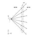
- six arrows indicate paths of components of radio waves radiated from the base station antenna 50 that enter the centers of six rectangular regions 121.
- Figs. 2A to 2C are used to explain the paths of radio waves.
- Figs. 2A to 2C are diagrams showing an example of paths of components of radio waves radiated from the base station antenna 50 that pass through the centers of the rectangular regions 121.
- Figs. 1 and 2A to 2C show paths of components of radio waves radiated from the base station antenna 50 that enter the centers of the rectangular regions 121 and exit, but hereinafter, these will be simply described as paths of radio waves.
- the window glass 10 is omitted, and only the base station antenna 50 and the radio wave propagation control member 100 are shown.
- the rectangular region 121 of the propagation control layer 120 included in the radio wave propagation control member 100 is described as existing along the XY plane as shown in Figure 1.
- FIG. 2A shows the path of radio waves in the XZ plane (horizontal plane), and FIG. 2B and FIG. 2C show the path of radio waves in the YZ plane.
- the YZ plane shows a cross section of the radio wave propagation control member 100 as seen from the side.
- the path of radio waves is shown as a path that passes through the center of each rectangular region 121.
- Figure 1 shows the paths of six radio waves propagating from the base station antenna 50 to the rectangular area 121 in six columns in the fourth row from the top of the radio wave propagation control member 100.
- the radio waves also propagate to the rectangular areas 121 in the first to third rows and the fifth to sixth rows from the top of the radio wave propagation control member 100, but for ease of understanding, Figure 1 only shows the area in the fourth row.
- FIG. 2A shows the paths of six radio waves incident on the six rectangular regions 121 in the fourth row when viewed in a horizontal plane.
- the angles of incidence and emergence of the six radio waves with respect to the radio wave propagation control member 100 when they pass through the centers of the six rectangular regions 121 are different from one another.
- the angles of incidence and emergence of each radio wave with respect to the radio wave propagation control member 100 when they pass through the center of each rectangular region 121 are equal.
- the paths of the six radio waves passing through the six rectangular regions 121 in the first to third rows and the fifth to sixth rows from the top of the radio wave propagation control member 100 are equal to the paths of the six radio waves passing through the six rectangular regions 121 in the fourth row shown in FIG. 2A.
- the paths of the six radio waves actually represent the paths of the components of the radio waves that have a wider beam width and that pass through the center of the rectangular area 121. Therefore, the angles of incidence and emergence of the six radio wave paths with respect to the radio wave propagation control member 100 when passing through the centers of the six rectangular areas 121 are different from one another, making it possible to widen the beam width two-dimensionally.
- FIG. 2B also shows the paths of six radio waves that are incident on six rectangular regions 121 in the first to sixth rows in a YZ side view.
- the six radio waves are incident on the centers of the six rectangular regions 121 in the first to sixth rows at different angles of incidence, but the exit angles when they are emitted to the outdoors from the six rectangular regions 121 in the first to sixth rows are equal, as an example.
- the radio wave propagation control member 100 refracts each of the six radio waves so that the angles of incidence and exit of the six radio waves are in the relationship described above.
- the paths of the six radio waves in a YZ side view shown in FIG. 2B are equal in the six rectangular regions 121 in the first to sixth columns of each row, as an example.
- radio waves are emitted downward to the outdoors from the six rectangular regions 121 in the first to sixth rows, so that millimeter waves such as those of the fifth generation mobile communication system (5G) reach the below of the window glass 10 on which the radio wave propagation control member 100 is provided.
- a base station BS provided inside the building
- radio waves radiated from a base station BS provided inside the building can be supplied to a mobile terminal device such as a smartphone or tablet computer carried by a person on the ground on the road or in a plaza outside the building.
- a communication area can be provided in which a mobile terminal device such as a smartphone or tablet computer carried by a person on the ground on the road or in a plaza outside the building can communicate with a base station BS provided inside the building.
- FIG. 2C also shows a modified example of the paths of six radio waves that respectively enter six rectangular regions 121 in the first to sixth rows in a YZ side view.
- FIG. 2C as in FIG. 2B, the angles of incidence when the six radio waves enter the centers of the six rectangular regions 121 in the first to sixth rows are different from each other.
- FIG. 2C the angles of emergence when the six radio waves are emitted to the outdoors from the six rectangular regions 121 in the first to sixth rows are also different from each other, and the six radio waves propagate to approximately the same position in a YZ side view.
- the radio wave propagation control member 100 refracts each radio wave so that the angles of incidence and emergence of the six radio waves have the above-mentioned relationship.
- the paths of the six radio waves in a YZ side view shown in FIG. 2C are, as an example, the same in the six rectangular regions 121 in the first to sixth columns of each row.
- radio waves are emitted from the six rectangular regions 121 in the first to sixth rows to approximately the same position below the outdoor side, so that millimeter waves such as those of the fifth generation mobile communication system (5G) reach below the window glass 10 on which the radio wave propagation control member 100 is provided.
- radio waves can be concentrated in an area narrower in width in the Z direction than in FIG. 2B.
- a mobile terminal such as a smartphone or tablet computer carried by a person on the ground on the outdoor side of the building, such as on a road or in a square, can communicate with a base station BS provided inside the building, providing a communication area narrower in width in the Z direction.
- radio wave propagation control member 100 has been described in terms of a configuration in which the radio wave propagation control member 100 refracts radio waves downward, the radio wave propagation control member 100 may refract radio waves in directions other than downward. Therefore, by using the radio wave propagation control member 100, radio waves can be refracted in various directions.
- the propagation control layer 120 of the radio wave propagation control member 100 as described above can be realized by a Fresnel lens, for example.
- a Fresnel lens for example.
- the results of a simulation in which the propagation control layer 120 shown in FIG. 1 is realized by a Fresnel lens will be described.
- Figure 3 is a diagram showing an example of the intensity distribution of radio waves incident on the propagation control layer 120 in a simulation.
- the dimension in the X direction (-150 mm to 150 mm) and the dimension in the Y direction (-150 mm to 150 mm) represent the range in which the propagation control layer 120 exists when viewed from the XY plane.
- the multiple rectangular regions 121 of the propagation control layer 120 are arranged in the range of -150 mm to 150 mm in the X direction and -150 mm to 150 mm in the Y direction.
- the position where the X and Y coordinates are 0 mm is the center of the propagation control layer 120 when viewed from the XY plane.
- the simulation conditions were set so that the incidence angle and the emission angle of the radio wave in the XZ plane view are equal when passing through the propagation control layer 120, as shown in FIG. 2A. Further, the simulation conditions were set so that the emission angle of the radio wave in the YZ side view is in the direction of an elevation angle of -60 degrees when passing through the propagation control layer 120, as shown in FIG. 2B.
- the elevation angle is the angle between a certain direction vector seen from the origin of the XYZ coordinate system, with the center of the propagation control layer 120 as the origin, and its projection onto the horizontal plane (XZ plane). The sign of the elevation angle is positive in the +Y direction from the horizontal plane (XZ plane).
- the Y direction is an elevation angle of +90 degrees
- the -Y direction is an elevation angle of -90 degrees.
- an azimuth angle is used.
- the azimuth angle is the angle between the projection of a certain direction vector seen from the origin of the XYZ coordinate system, with the center of the propagation control layer 120 as the origin, and the Z axis.
- the sign of the azimuth angle is positive when the counterclockwise direction from the Z axis to the X axis is positive when looking at the horizontal plane (XZ plane) from the +Y direction.
- the X direction is an azimuth angle of +90 degrees
- the -X direction is an azimuth angle of -90 degrees.
- the intensity distribution shown in Figure 3 was obtained on the XY plane.
- the radio wave intensity distribution was strongest at the center of the propagation control layer 120 and gradually weakened toward the outside in the radial direction.
- FIGS. 4A to 4C are diagrams showing a simulation model of the propagation control layer 120 and an example of a simulation result of the intensity of radio waves at a position sufficiently distant from the radio wave propagation control member 100.
- the left side shows the Fresnel lens pattern (simulation model) of the propagation control layer 120 used in the simulation.
- the white parts are parts where the phase of the radio waves (transmitted waves) that have passed through the propagation control layer 120 is +180 degrees
- the black parts are parts where the phase of the transmitted waves is -180 degrees.
- the gradation parts between white and black are parts where the phase of the transmitted waves is delayed as it becomes darker.
- the right side shows the intensity distribution of radio waves that have passed through the propagation control layer 120 composed of the Fresnel lens on the left side.
- the intensity distribution shown on the right side is calculated as the intensity distribution obtained at a position sufficiently distant from the radio wave propagation control member 100.
- the horizontal axis indicates the azimuth angle
- the vertical axis indicates the elevation angle. Note that the position where the azimuth angle and elevation angle are both 0 degrees is the position on the Z axis.
- FIGS 4A to 4C show the Fresnel lens pattern (left) and the radio wave intensity distribution (right) when the propagation control layer 120 is divided in the X direction without being divided in the Y direction to provide multiple rectangular regions 121. That is, each rectangular region 121 is a strip-shaped rectangular region 121 with a length in the Y direction of 300 mm and a length in the X direction that divides a 300 mm section into multiple sections.
- the division was performed so that the angular difference (angle difference in the azimuth direction) between adjacent paths connecting the base station antenna 50 and the center of each rectangular region 121 in the XY plane view is less than 1 degree in FIG. 4A, 1 degree in FIG. 4B, and 5 degrees in FIG. 4C.
- An angular difference of 1 degree between adjacent paths in the XZ plane view corresponds to an angular difference of 1 degree between adjacent paths among the six paths shown in FIG. 2A.
- An angular difference of 5 degrees between adjacent paths in the XZ plane view corresponds to an angular difference of 5 degrees between adjacent paths among the six paths shown in FIG. 2A.
- An angular difference of less than 1 degree between adjacent paths in the XZ plane view means that an angular difference of less than 1 degree between adjacent paths among the six paths shown in FIG. 2A.
- FIGS. 5A to 5C are diagrams showing a simulation model of the propagation control layer 120 and an example of the simulation results of the intensity of radio waves at a position sufficiently distant from the radio wave propagation control member 100.
- the left side shows the Fresnel lens pattern (simulation model) of the propagation control layer 120 used in the simulation.
- the right side shows the intensity distribution of radio waves that have passed through the propagation control layer 120 composed of the Fresnel lens on the left side.
- the intensity distribution shown on the right side is calculated as an intensity distribution obtained at a position sufficiently distant from the radio wave propagation control member 100.
- the horizontal axis shows the azimuth angle and the vertical axis shows the elevation angle. Note that the position where the azimuth angle and elevation angle are both 0 degrees is the position on the Z axis.
- FIGS 5A to 5C show the Fresnel lens pattern (left) and the radio wave intensity distribution (right) when the propagation control layer 120 is divided in the X and Y directions to provide multiple rectangular regions 121. That is, each rectangular region 121 has a length in the X direction obtained by dividing a section of 300 mm into multiple sections, and a length in the Y direction obtained by dividing a section of 300 mm into multiple sections. As an example, the divisions in the X and Y directions are equal.
- the division was performed so that the angular difference (angle difference in the azimuth direction) between adjacent paths in the XZ plane view and the angular difference (angle difference in the elevation direction) between adjacent paths in the YZ plane view for paths connecting the base station antenna 50 and the center of each rectangular region 121 in the XY plane view are less than 1 degree in Fig. 5A, 1 degree in Fig. 5B, and 5 degrees in Fig. 5C.
- An angular difference of 1 degree between adjacent paths in the XZ plane view and the XZ plane view corresponds to an angular difference of 1 degree between adjacent paths of the six paths shown in Fig.
- An angle difference of 5 degrees between adjacent paths when viewed from the XZ plane corresponds to an angle difference of 5 degrees between adjacent paths among the six paths shown in FIG. 2A and an angle difference of 5 degrees between adjacent paths among the six paths shown between the base station antenna 50 and the radio wave propagation control member 100 in FIG. 2B.
- An angle difference of less than 1 degree between adjacent paths when viewed from the XZ plane corresponds to an angle difference of less than 1 degree between adjacent paths among the six paths shown in FIG. 2A and an angle difference of less than 1 degree between adjacent paths among the six paths shown between the base station antenna 50 and the radio wave propagation control member 100 in FIG. 2B.
- the communication area can be provided below the outdoor side of the window glass 10 of a building when a propagation control layer 120 is used that is realized by a Fresnel lens having the pattern shown on the left side of Figures 4A, 4B, 5A, and 5B.
- the Fresnel lens pattern shown on the left side of Figures 4A and 4B includes a plurality of rectangular regions 121 obtained by dividing the propagation control layer 120 in the X direction without dividing it in the Y direction, and when the wavelength in free space of the radio wave arriving at the propagation control layer 120 is ⁇ 0 , the length of the short side (length in the X direction) is 2 ⁇ 0 or less.
- the plurality of rectangular regions 121 are arranged in the X direction and the Y direction. Note that there is no particular limit to the length of the long side (length in the Y direction) of the rectangular region 121.
- 5A and 5B includes a plurality of rectangular regions 121 obtained by dividing the propagation control layer 120 in the X direction and the Y direction, and when the wavelength in free space of the radio wave arriving at the propagation control layer 120 is ⁇ 0 , the length of the short side is 2 ⁇ 0 or less, and the length of the long side (length in the Y direction) is also 2 ⁇ 0 or less.
- the plurality of rectangular regions 121 are arranged in the X direction and the Y direction. When the lengths of the short side and the long side are the same, the rectangular region 121 becomes a square.
- Each of the rectangular regions 121 included in the Fresnel lens pattern shown on the left side of Figures 4A, 4B, 5A, and 5B has a belt-like pattern, and the belt-like pattern of each rectangular region 121 refracts radio waves in a downward direction (a predetermined direction), and the refraction directions of the radio waves due to the belt-like patterns of the rectangular regions 121 are different from each other.
- the belt-like pattern of each rectangular region 121 is belt-like inside each rectangular region 121 so as to correspond to the part below the center of the concentric Fresnel lens pattern, and is also belt-like across adjacent rectangular regions 121 in the X direction.
- the length of the rectangular region 121 in the X direction in FIG. 4A is about 1 mm, that is, about 0.09 ⁇ 0
- the length of the rectangular region 121 in the X direction in FIG. 4B is about 9 mm, that is, about 0.81 ⁇ 0.
- the length of the rectangular region 121 in the X direction and the Y direction in FIG. 5A is about 1 mm, that is, about 0.09 ⁇ 0
- the length of the rectangular region 121 in the X direction and the Y direction in FIG. 5B is about 9 mm, that is, about 0.81 ⁇ 0.
- the length of the rectangular region 121 in the X direction is about 17 mm, that is, about 1.55 ⁇ 0.
- the rectangular region 121 is divided with the azimuth angle and the elevation angle set to a constant value, so the farther from the origin, the longer the length in the X direction and the Y direction. From this result, it was found that the length in the X direction (length of the short side) of the rectangular region 121 is more preferably 1.5 ⁇ 0 or less, even more preferably ⁇ 0 or less, even more preferably 0.5 ⁇ 0 or less, and even more preferably 0.1 ⁇ 0 or less. The same was true for the length in the Y direction (length of the long side) of the rectangular region 121.
- the angle between the propagation directions of radio waves passing through adjacent rectangular regions 121 is 2 degrees or less.
- the band patterns of adjacent rectangular regions 121 are arranged in a curved line.
- the Fresnel lens pattern is a continuous curved line pattern of the band patterns of adjacent rectangular regions 121.
- the difference in the direction of radio waves entering adjacent rectangular regions 121 from the base station antenna 50 is less than 2 degrees.
- Fig. 6A is a diagram showing an example of the overall configuration of the propagation control layer 120 composed of a Fresnel zone plate. Fig. 6A also shows the base 110 on which the propagation control layer 120 is formed.
- the base 110 on which the propagation control layer 120 is formed is composed of a Fresnel zone plate, not a Fresnel lens.
- the propagation control layer 120 constituting the Fresnel zone is an example of a metal layer.
- the propagation control layer 120 shown in FIG. 6A is composed of a metal layer formed on the surface of the base 110.
- the propagation control layer 120 shown in FIG. 6A has a length of 2000 mm in the X direction and a length of 400 mm in the Y direction.
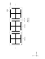
- Figure 6B is a diagram showing an example of a conductor 120A included in a frequency selective surface (FSS).
- the conductor 120A is an example of a unit pattern conductor.
- Figure 6B shows three adjacent conductors 120A as an example.
- the black parts are parts made of metal.
- Each conductor 120A is provided within a square-shaped unit cell 120U, which is a unit area.
- Three adjacent conductors 120A are arranged within three adjacent unit cells 120U.
- the conductor 120A has a shape in which a straight conductor extending along the four sides of the unit cell 120U is added to the end of a +-shaped conductor extending in the X and Y directions.
- the four straight conductors extending along the four sides are separated from each other at the four corners of the unit cell 120U.
- the line width of each straight portion of the conductor 120A is 0.1 mm
- the length of the unit cell 120U in the X and Y directions is 1.5 mm.
- the pitch in the X direction between adjacent conductors 120A is 1.5 mm.
- the length of the straight conductor extending along the four sides of the unit cell 120U is 1.0 mm
- the gap between adjacent conductors 120A is, as an example, 0.13 mm.
- Each conductor 120A may be formed of a transparent conductive film such as zinc oxide (ZnO), tin oxide (SnO 2 ), tin-doped indium oxide (ITO), indium oxide-tin oxide (IZO), or the like, a metal nitride such as titanium nitride (TiN) or chromium nitride (CrN), or a low-e film for low-e glass.
- a transparent conductive film such as zinc oxide (ZnO), tin oxide (SnO 2 ), tin-doped indium oxide (ITO), indium oxide-tin oxide (IZO), or the like, a metal nitride such as titanium nitride (TiN) or chromium nitride (CrN), or a low-e film for low-e glass.
- a mesh-like metal thin film such as copper, nickel, or gold.
- the propagation control layer 120 shown in FIG. 6A is an arrangement of a large number of conductors 120A as shown in FIG. 6B.
- the shape of the conductors 120A shown in FIG. 6B is merely an example, and the propagation control layer 120 may include conductors 120A having various shapes. Since the amount of delay that the conductors 120A cause to the radio waves varies depending on the shape, arranging conductors 120A of various shapes makes it possible to refract the radio waves. Note that the metal layers included in the conductors 120A may be two or more layers.
- the outer edges of the unit cells 120U of adjacent conductors 120A are in contact with each other.
- a band-shaped pattern as shown in FIG. 6A can be realized.
- the band-shaped pattern of the propagation control layer 120 shown in FIG. 6A constitutes a metasurface in which multiple unit pattern conductors are arranged.
- Each rectangular region 121 includes, as an example, a number of unit cells 120U. Therefore, within each rectangular region 121, the conductors 120A form a strip-shaped pattern.
- the conductors 120A form a strip-shaped pattern when the outer edges of adjacent unit cells 120U included in the unit cells 120U of the conductors 120A are in contact with each other.
- a continuous band pattern is obtained over the entire propagation control layer 120 having a large size, such as 2000 mm in the X direction and 400 mm in the Y direction, as shown in FIG. 6A.
- the band patterns of adjacent rectangular regions 121 tend to be smoothly connected to each other.
- the band patterns of adjacent rectangular regions 121 are arranged in a curved line.
- each rectangular region 121 may include one unit cell 120U. In other words, each rectangular region 121 may include one conductor 120A. In such a case, when multiple rectangular regions 121 each including one conductor 120A are arranged, radio waves refracted by the multiple conductors 120A may propagate in multiple refraction directions, for example, as shown in Figures 2A to 2C.
- Fig. 7 is a diagram showing an example of an experimental result using the propagation control layer 120 shown in Fig. 6.
- the propagation control layer 120 shown in Fig. 6 was provided on the window glass 10 on the fifth floor of a building, radio waves were emitted from the base station antenna 50 installed indoors on the fifth floor of the building, and the radio wave intensity distribution was measured within an area of 35m x 11m and 1.2m above the ground, 3m away from the building, and expressed as a cumulative distribution function (CDF) of the received power.
- CDF cumulative distribution function
- the radio wave strength increases by about 5 dB when the propagation control layer 120 is present compared to when the propagation control layer 120 is not present.
- the CDF is about 0.1 or more, it was confirmed that the radio wave strength increases when the propagation control layer 120 is present compared to when the propagation control layer 120 is not present.
- the propagation control layer 120 is made of a metal layer, but the base 110 and the propagation control layer 120 may be integrated into a Fresnel lens.
- the radio wave propagation control member 100 includes a base 110 and a propagation control layer 120 provided on the base 110, the propagation control layer 120 has a plurality of rectangular regions 121 in a plan view, each rectangular region 121 has a band pattern formed by the propagation control layer 120, and the rectangular region 121 has a short side length of 2 ⁇ 0 or less, where ⁇ 0 is the wavelength in free space of the radio wave arriving at the propagation control layer 120, and the band pattern of each rectangular region 121 refracts the radio wave in a predetermined direction, and the refraction directions of the radio wave by the plurality of band patterns are different from each other.
- the length of the short side of the rectangular region 121 is more preferably 1.5 ⁇ 0 or less, more preferably ⁇ 0 or less, even more preferably 0.5 ⁇ 0 or less, and even more preferably 0.1 ⁇ 0 or less.
- radio wave propagation control member 100 that can expand the beam width two-dimensionally.
- the multiple rectangular regions 121 are arranged in the X direction (first axis direction) and the Y direction (second axis direction) in a plan view of the propagation control layer 120, and the length of the long side of the rectangular region 121 may be 2 ⁇ 0 or less. Therefore, the planar size of the rectangular region 121 can be reduced, null points are less likely to occur, and a stable communication area can be generated in a predetermined direction.
- strip patterns of adjacent rectangular regions 121 may be connected to each other. This makes it possible to generate a wider range of stable communication areas in a specified direction with fewer null points.
- the angle between the propagation directions of radio waves passing through adjacent rectangular areas 121 may be 2 degrees or less. This makes it difficult for null points to occur, and a stable communication area can be generated in a specified direction.
- strip patterns of adjacent rectangular regions 121 may be arranged in a curved line. This makes it possible to generate a stable communication area in a specified direction over a wider range with fewer null points.
- the band pattern may also be made of a metal mesh. This allows for the radio wave propagation control member 100 to be realized as a transparent band pattern that is difficult to see and is colorless and transparent.
- the propagation control layer 120 may also be a transparent conductive layer or a Low-E film. This allows for the realization of a colorless and transparent radio wave propagation control member 100 that is difficult to see with the naked eye, thanks to its transparent band-like pattern.
- the band pattern may form a metasurface in which multiple unit pattern conductors are arranged. Therefore, by utilizing the band pattern formed by the metasurface, it is possible to provide a radio wave propagation control member 100 that can more freely expand the beam width in two dimensions.
- the base 110 may also be a glass plate. This allows the propagation control layer 120 to be easily formed, and provides a radio wave propagation control member 100 that can expand the beam width two-dimensionally. If the glass plate is transparent, a colorless and transparent radio wave propagation control member 100 that is difficult to see can be realized.
- the base 110 may also be a resin film. This allows the propagation control layer 120 to be easily formed, and provides a radio wave propagation control member 100 that can expand the beam width two-dimensionally. If the resin film is transparent, a colorless and transparent radio wave propagation control member 100 that is difficult to see can be realized.
- the base 110 may be a resin film, and the radio wave propagation control member 100 may be installed on the window glass 10. This allows the propagation control layer 120 to be easily installed on the window glass 10, and provides a radio wave propagation control member 100 that can expand the beam width two-dimensionally through the window glass 10.
- the radio waves may be in the Sub-6 band or the millimeter wave band. It is possible to provide a radio wave propagation control member 100 that is capable of expanding the beam width two-dimensionally while supporting communication in the Sub-6 band or the millimeter wave band.
- the radio wave propagation control member 100 includes a base 110 and a propagation control layer 120 provided on the base 110, the propagation control layer 120 having a plurality of rectangular regions 121 in a planar view, each rectangular region 121 having a metal pattern configured by the propagation control layer 120, the rectangular regions 121 having a short side length of 2 ⁇ 0 or less when the wavelength in free space of the radio wave arriving at the propagation control layer 120 is ⁇ 0 , and the radio waves refracted by the metal pattern of the plurality of rectangular regions 121 may be configured to propagate in a plurality of refraction directions.
- each rectangular region 121 may include one conductor 120A.
- radio waves refracted by the multiple conductors 120A may propagate in multiple refraction directions, as shown in Figures 2A to 2C, for example.
- the antenna system 200 includes a base station antenna 50 installed indoors and the radio wave propagation control member 100 installed on the window glass 10. This allows the radio wave beam width to be expanded two-dimensionally.
- the difference in the incident direction of radio waves incident from the base station antenna 50 on adjacent rectangular regions 121 may be 2 degrees or less.
- the difference in the emission direction of radio waves that have passed through the propagation control layer 120 is also small, making it difficult for null points to occur and enabling a stable communication area to be generated in a specified direction.
- Base station 10 Window glass BS Base station 50 Base station antenna 100 Radio wave propagation control member 110 Base body 120 Propagation control layer (an example of a metal layer) 120A conductor (an example of a unit pattern conductor) 120U unit cell 121 rectangular area 200 antenna system
Landscapes
- Physics & Mathematics (AREA)
- Electromagnetism (AREA)
- Aerials With Secondary Devices (AREA)
Priority Applications (1)
| Application Number | Priority Date | Filing Date | Title |
|---|---|---|---|
| JP2024573022A JPWO2024157897A1 (https=) | 2023-01-26 | 2024-01-19 |
Applications Claiming Priority (2)
| Application Number | Priority Date | Filing Date | Title |
|---|---|---|---|
| JP2023010464 | 2023-01-26 | ||
| JP2023-010464 | 2023-01-26 |
Publications (1)
| Publication Number | Publication Date |
|---|---|
| WO2024157897A1 true WO2024157897A1 (ja) | 2024-08-02 |
Family
ID=91970623
Family Applications (1)
| Application Number | Title | Priority Date | Filing Date |
|---|---|---|---|
| PCT/JP2024/001482 Ceased WO2024157897A1 (ja) | 2023-01-26 | 2024-01-19 | 電波伝搬制御部材、及び、アンテナシステム |
Country Status (2)
| Country | Link |
|---|---|
| JP (1) | JPWO2024157897A1 (https=) |
| WO (1) | WO2024157897A1 (https=) |
Citations (2)
| Publication number | Priority date | Publication date | Assignee | Title |
|---|---|---|---|---|
| JP2015141547A (ja) * | 2014-01-29 | 2015-08-03 | 日本電気株式会社 | 情報処理装置、監視方法、及び、プログラム |
| WO2022091986A1 (ja) * | 2020-10-30 | 2022-05-05 | 京セラ株式会社 | 通信システム、通信方法、および電波屈折板の設置方法 |
-
2024
- 2024-01-19 JP JP2024573022A patent/JPWO2024157897A1/ja active Pending
- 2024-01-19 WO PCT/JP2024/001482 patent/WO2024157897A1/ja not_active Ceased
Patent Citations (2)
| Publication number | Priority date | Publication date | Assignee | Title |
|---|---|---|---|---|
| JP2015141547A (ja) * | 2014-01-29 | 2015-08-03 | 日本電気株式会社 | 情報処理装置、監視方法、及び、プログラム |
| WO2022091986A1 (ja) * | 2020-10-30 | 2022-05-05 | 京セラ株式会社 | 通信システム、通信方法、および電波屈折板の設置方法 |
Non-Patent Citations (1)
| Title |
|---|
| LEE WONWOO, JO SEMIN, LEE KANGHYEOK, PARK HONG SOO, YANG JUNHYUK, HONG HA YOUNG, PARK CHANGKUN, HONG SUN K., LEE HOJIN: "Single-layer phase gradient mmWave metasurface for incident angle independent focusing", SCIENTIFIC REPORTS, NATURE PUBLISHING GROUP, US, vol. 11, no. 1, 16 June 2021 (2021-06-16), US , pages 12671 , XP093194026, ISSN: 2045-2322, DOI: 10.1038/s41598-021-92083-5 * |
Also Published As
| Publication number | Publication date |
|---|---|
| JPWO2024157897A1 (https=) | 2024-08-02 |
Similar Documents
| Publication | Publication Date | Title |
|---|---|---|
| US20250174903A1 (en) | Frequency-selective reflecting plate and communication relay system | |
| US11482790B2 (en) | Dielectric lens and electromagnetic device with same | |
| JP7566643B2 (ja) | リフレクトアレー、リフレクトアレーの設計方法、および、リフレクトアレーシステム | |
| US20250309551A1 (en) | Radio transmission system | |
| EP0343813A2 (en) | Radar transparent materials | |
| TW202245339A (zh) | 相位調整板、玻璃板及無線通信系統 | |
| CN102231456A (zh) | 双频段双极化共口径天线 | |
| US20100001918A1 (en) | Passive repeater antenna | |
| KR20250018470A (ko) | 전자파 반사 장치, 전자파 반사 펜스 및 반사 패널 | |
| WO2023218887A1 (ja) | 電磁波反射装置、及び電磁波反射フェンス | |
| WO2024157897A1 (ja) | 電波伝搬制御部材、及び、アンテナシステム | |
| WO2023210566A1 (ja) | 周波数選択反射板 | |
| US20250096480A1 (en) | Electromagnetic wave reflecting device, electromagnetic wave reflecting fence, and reflection panel | |
| JP2024021078A (ja) | 電波反射体、電波反射体の製造方法および電波反射体の施工方法 | |
| TW202425422A (zh) | 反射板、使用其之電磁波反射裝置及電磁波反射柵 | |
| WO2024095750A1 (ja) | 電波伝送システム、及び、電波伝送方法 | |
| KR101408070B1 (ko) | 반사배열 안테나 | |
| JP2025068576A (ja) | リフレクトアレイユニット | |
| US20240339756A1 (en) | Planar transparent antenna structure | |
| WO2025135029A1 (ja) | 電波反射体 | |
| WO2025177989A1 (ja) | 近傍界伝送装置 | |
| TW202410551A (zh) | 無線傳輸系統 | |
| US20250274777A1 (en) | Communication system, radio wave refraction plate, and method for calculating installation position of radio wave refraction plate | |
| TW202410552A (zh) | 反射板、使用其之電磁波反射裝置、及電磁波反射柵 | |
| TW202401907A (zh) | 反射器 |
Legal Events
| Date | Code | Title | Description |
|---|---|---|---|
| 121 | Ep: the epo has been informed by wipo that ep was designated in this application |
Ref document number: 24747225 Country of ref document: EP Kind code of ref document: A1 |
|
| ENP | Entry into the national phase |
Ref document number: 2024573022 Country of ref document: JP Kind code of ref document: A |
|
| WWE | Wipo information: entry into national phase |
Ref document number: 2024573022 Country of ref document: JP |
|
| NENP | Non-entry into the national phase |
Ref country code: DE |
|
| 122 | Ep: pct application non-entry in european phase |
Ref document number: 24747225 Country of ref document: EP Kind code of ref document: A1 |