WO2024157763A1 - 操作装置及び操作システム - Google Patents
操作装置及び操作システム Download PDFInfo
- Publication number
- WO2024157763A1 WO2024157763A1 PCT/JP2024/000296 JP2024000296W WO2024157763A1 WO 2024157763 A1 WO2024157763 A1 WO 2024157763A1 JP 2024000296 W JP2024000296 W JP 2024000296W WO 2024157763 A1 WO2024157763 A1 WO 2024157763A1
- Authority
- WO
- WIPO (PCT)
- Prior art keywords
- unit
- operating device
- predetermined value
- operating
- pressing
- Prior art date
- Legal status (The legal status is an assumption and is not a legal conclusion. Google has not performed a legal analysis and makes no representation as to the accuracy of the status listed.)
- Ceased
Links
Images
Classifications
-
- G—PHYSICS
- G06—COMPUTING OR CALCULATING; COUNTING
- G06F—ELECTRIC DIGITAL DATA PROCESSING
- G06F3/00—Input arrangements for transferring data to be processed into a form capable of being handled by the computer; Output arrangements for transferring data from processing unit to output unit, e.g. interface arrangements
- G06F3/01—Input arrangements or combined input and output arrangements for interaction between user and computer
- G06F3/02—Input arrangements using manually operated switches, e.g. using keyboards or dials
-
- G—PHYSICS
- G06—COMPUTING OR CALCULATING; COUNTING
- G06F—ELECTRIC DIGITAL DATA PROCESSING
- G06F3/00—Input arrangements for transferring data to be processed into a form capable of being handled by the computer; Output arrangements for transferring data from processing unit to output unit, e.g. interface arrangements
- G06F3/01—Input arrangements or combined input and output arrangements for interaction between user and computer
- G06F3/03—Arrangements for converting the position or the displacement of a member into a coded form
- G06F3/033—Pointing devices displaced or positioned by the user, e.g. mice, trackballs, pens or joysticks; Accessories therefor
- G06F3/0354—Pointing devices displaced or positioned by the user, e.g. mice, trackballs, pens or joysticks; Accessories therefor with detection of two-dimensional [2D] relative movements between the device, or an operating part thereof, and a plane or surface, e.g. 2D mice, trackballs, pens or pucks
Definitions
- the present invention relates to an operating device that outputs an operating signal in response to a pressing operation, and an operating system that uses such an operating device.
- a mouse is used as an operating device for operating an operated device such as a computer or a game device.
- an operating part such as a mouse button or a mouse wheel
- the mouse outputs an operating signal based on the pressing operation to the operated device.
- the present invention was made in consideration of these circumstances, and its main objective is to provide an operating device that can improve operability.
- Another object of the present invention is to disclose an operating system that uses the operating device according to the present invention.
- the operating device disclosed in the present application is an operating device that includes an operating section that moves in response to a pressing operation, and outputs an operating signal as the operating section moves, and is characterized in that it includes a detection section that can detect a physical quantity that changes when the operating section moves, a determination means that determines whether the rate of change in the physical quantity detected by the detection section exceeds a preset predetermined value, and a means that outputs an operating signal when it is determined that the rate of change in the measured physical quantity exceeds the predetermined value.
- the operating device disclosed in the present application is an operating device that includes an operating unit that moves from a first position to a second position in response to a pressing operation, and outputs an operating signal when the operating unit moves to the second position, and is characterized in that it includes a detection unit capable of detecting the position of the operating unit, a determination means that determines whether or not the moving speed of the operating unit has exceeded a predetermined value based on the position detected by the detection unit, and a means that outputs an operating signal before the operating unit reaches the second position when it is determined that the moving speed has exceeded the predetermined value.
- the operating device further includes a measuring means for measuring the time it takes for the operating part to move from the first position to a third position between the first position and the second position, and the determining means determines that the moving speed has exceeded the predetermined value when the time measured by the measuring means is equal to or less than a predetermined value.
- the operating device disclosed in the present application is an operating device that includes an operating unit that moves from a first position to a second position in response to a pressing operation, and outputs an operating signal when the operating unit moves to the second position, and is characterized in that it includes a detection unit capable of detecting a load pressing the operating unit, a determination means for determining whether or not the increasing speed of the load detected by the detection unit exceeds a predetermined value, and a means for outputting an operating signal before the second position is reached when it is determined that the increasing speed exceeds the predetermined value.
- the operating device further includes a measuring means for measuring the time it takes for the load caused by the pressing operation to reach a third load required for pressing from a first load at the first position to a third position between the first position and the second position, and the determining means determines that the rate of increase in the load caused by pressing has exceeded a predetermined value when the time measured by the measuring means is equal to or less than a predetermined value.
- the operating device is also characterized in that it includes a feel generating unit that changes the feel of the operation on the operating unit when the determining means determines that the predetermined value is exceeded.
- the sensation generating unit is characterized by increasing or decreasing the load required to generate vibration or press the operating unit.
- the detection unit is characterized by using a piezoelectric element, an element that detects electrostatic capacitance, or an element that detects changes in a magnetic field.
- the operation system disclosed in the present application is an operation system using an operation device that has an operation unit that moves in response to a pressing operation and outputs an operation signal as the operation unit moves, and is characterized in that it has a detection unit that can detect a physical quantity that changes when the operation unit moves, a determination means that determines whether the rate of change in the physical quantity detected by the detection unit exceeds a predetermined value that has been set in advance, and a means that outputs an operation signal when it is determined that the rate of change in the measured physical quantity exceeds the predetermined value.
- the operating device etc. disclosed in this application uses an operating device that outputs an operating signal when an operating part moves, and outputs an operating signal to the operating part when the rate of change in a physical quantity that changes when the operating part moves exceeds a predetermined value. This allows the operating device etc. disclosed in this application to achieve excellent effects such as improved operability.
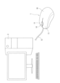
- FIG. 1 is a schematic perspective view showing an example of the appearance of an operation system disclosed herein;
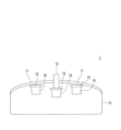
- FIG. 2 is an explanatory diagram conceptually illustrating an example of an internal structure of the operating device disclosed herein.
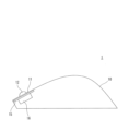
- FIG. 2 is an explanatory diagram conceptually illustrating an example of an internal structure of the operating device disclosed herein.
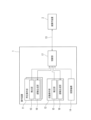
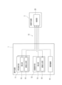
- 1 is a functional block diagram showing a configuration example of a switching function by an operating device and an operated device used in the operation system disclosed in the present application.
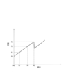
- FIG. 1 is a graph showing an example of FS characteristics in a manipulation device disclosed herein.
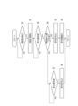
- 11 is a flowchart illustrating an example of a process in the operation system disclosed in the present application.
- 1 is a functional block diagram showing a configuration example of a switching function by an operating device and an operated device used in the operation system disclosed in the present application.
- the operation device disclosed in the present application is used as an operation device such as a mouse used to operate an operated device such as a personal computer (hereinafter referred to as a PC) or a game device.
- an operation system using an operation device 1 and an operated device 2 illustrated in the drawings will be described with reference to the drawings.
- the operation system disclosed in the present application is used, for example, for playing and operating a game in which quick operation is effective.
- FIG. 1 is a schematic perspective view showing an example of the appearance of the operation system disclosed in the present application.
- FIG. 1 shows an example of the operation system disclosed in the present application, in which the operation device 1 is applied to a mouse and the operated device 2 is applied to a personal computer.
- the operation device 1 includes a housing 10 that houses various mechanisms.
- the operation device 1 includes a pressing operation unit 11 (operation unit) such as a mouse button that accepts an operation of pressing with the operator's finger, and a rotating operation unit 12 (operation unit) such as a mouse wheel that accepts an operation of rotating with the operator's finger.
- the rotating operation unit 12 is configured to accept not only a rotating operation but also a pressing operation, and also functions as an operating unit that receives a pressing force.
- the operation device 1 is connected to a communication line 13 that mediates an operation signal to be output to an external operated device 2 such as a personal computer.
- the operation device 1 can output an operation signal not only by wired communication using the communication line 13, but also by various communication methods such as wireless communication.
- the direction of the operating device 1 will be described as the forward direction in which the communication line 13 is attached, the upward direction in which the pressing operation unit 11 and the rotating operation unit 12 are attached, and the downward direction in which the device is pressed.
- the pressing operation unit 11 and the rotating operation unit 12 move from top to bottom when pressed.
- the position in the released state where no pressure is applied is referred to as the upper limit position
- the limit position to which they move when pressed is referred to as the lower limit position.
- an opening/closing mechanism 14 (see FIG. 4, etc.) mounted inside is operated as a switch such as a microswitch or linear switch to open or close the circuit.
- switches can be used as the opening/closing mechanism 14.
- the opening/closing mechanism 14 is a microswitch that opens and closes a circuit by the snap action of a metal piece
- the vibration caused by the snap action gives the operator a tactile sensation due to the operation, a so-called clicking sensation.
- FIGS. 2 and 3 are explanatory diagrams conceptually showing an example of the internal structure of the operating device 1 disclosed in the present application.
- Fig. 2 and Fig. 3 conceptually show, in a simplified form, the pressing operation unit 11 and the rotating operation unit 12 and their related members as part of the internal structure of the operating device 1.
- Fig. 2 shows the operating device 1 from the front as seen through the inside
- Fig. 3 shows the operating device 1 from the side as seen through the inside.
- a detection unit 15 which serves as a sensor for detecting a physical quantity that changes when the pressing operation unit 11 moves from an upper limit position to a lower limit position.
- the detection unit 15 may be a capacitance sensor that detects the position (displacement) to which the pressing operation unit 11 moves by pressing using capacitance, or a magnetic field sensor using a Hall IC that detects changes in a magnetic field.
- the detection unit 15 may be a piezoelectric thin film that detects the load received by pressing as a change in electrical characteristics, or a piezo element. When implemented, either or both of the detection unit 15 that detects displacement and the detection unit 15 that detects load are disposed below the pressing operation unit 11. A similar detection unit 15 is also disposed below the rotation operation unit 12.
- the feel generating unit 16 is an actuator that has the function of generating a feel that the operator feels when the pressing operation unit 11 is pressed, a so-called click feeling.
- the feel generating unit 16 uses elements such as a piezoelectric thin film, a piezo element, and an electrostatic actuator that generate vibrations to make the operator feel the click feeling.
- the feel generating unit 16 generates a feel not only by vibration but also by various methods such as increasing or decreasing the load required for pressing, for example, by increasing or decreasing the load. It is also possible to configure the detection unit 15 and the feel generating unit 16 to be shared by a single element, for example, a piezoelectric thin film. A similar feel generating unit 16 is disposed below the rotating operation unit 12.
- ⁇ Function> 4 is a functional block diagram showing a configuration example of a switching function by the operating device 1 and the operated device 2 used in the operating system disclosed in the present application.
- the operating device 1 includes a control unit 17 such as a CPU in a housing 10.
- the control unit 17 is a circuit that controls the entire device, and is configured using a control circuit such as a microcomputer equipped with integrated circuits such as VLSI and LSI.
- the control unit 17 includes various circuits such as a memory circuit such as a semiconductor memory that stores various information such as various programs and data, and a timer circuit that measures time.
- the control circuit of the control unit 17 receives input of physical quantities detected by the detection unit 15 in response to operations on the pressing operation unit 11 and the rotating operation unit 12, executes various processes, outputs an operation signal to the operated device 2, and operates the sensation generating unit 16.
- FIG. 5 is a graph showing an example of the F-S characteristic of the operating device 1 disclosed in the present application.
- the F-S characteristic graph shown in FIG. 5 shows the relationship between the displacement (Stroke) when a pressing operation is performed on the pressing operation unit 11 provided in the operating device 1 on the horizontal axis and the pressing load (Force) related to the pressing operation on the vertical axis.
- the F-S characteristic shown in FIG. 5 is the characteristic of an operating device 1 that has a microswitch that opens and closes a circuit by the snap action of a metal piece as the opening and closing mechanism 14.
- the pressing operation unit 11 when the pressing operation unit 11 receives a pressing operation, it moves downward, and the load increases with the downward movement, i.e., with the change in displacement. Then, when the load of the pressing operation unit 11 reaches a predetermined position, the load changes significantly due to a snap action.
- the release position where the pressing operation unit 11 is not subjected to a pressing operation i.e., the upper limit position
- the 0th position which is the displacement P0.
- the opening/closing mechanism 14 When the pressing operation unit 11 receives a pressing operation, it moves from the displacement P1 that exceeds the play portion to the displacement P2, which is the lower limit position, and when it reaches the displacement P2, the opening/closing mechanism 14 operates as a snap action and outputs an operation signal.
- the position of displacement P0 which is the upper limit position
- the position of displacement P1 is set as the first position
- the position of displacement P2, which is the lower limit position is set as the second position. That is, the operating device 1 outputs an operation signal when the pressing operation unit 11 receives a pressing operation and moves from the first position to the second position.
- a third position of displacement P3 is set between the first position of displacement P1 and the second position of displacement P2.
- the loads for the operations at the 0th position, the first position, the second position, and the third position are load F0, load F1, load F2, and load F3, respectively.
- the operating device 1 disclosed in the present application can be set to various operation modes, such as normal mode and rapid-fire mode, depending on the application.
- normal mode the operating device 1 disclosed in the present application outputs an operation signal when the pressing operation unit 11, which has been pressed, moves to the second position of displacement P2.
- rapid-fire mode the operating device 1 disclosed in the present application outputs an operation signal at a third position before reaching the second position if the rate of change in the displacement or load of the pressing operation unit 11, which has been pressed, exceeds a predetermined value.
- FIG. 6 is a flowchart showing an example of processing in the operation system disclosed in the present application.
- FIG. 6 illustrates processing by the control unit 17 when the operation device 1 set to rapid-fire mode receives a pressing operation on the pressing operation unit 11.
- the control unit 17 provided in the operation device 1 detects, by the detection unit 15, whether or not the pressing operation unit 11 has detected the start of movement (step S1).
- step S1 the control unit 17 determines that the start of movement has been detected, for example, when the detection unit 15 detects that the pressing operation unit 11 has moved to a first position.
- the detection in step S1 is performed by detecting that the displacement has reached P1 or that the load has reached F1, or by the logical OR or AND of these.
- step S1 If the start of movement is detected in step S1 (step S1: YES), the control unit 17 starts measuring time (step S2) and determines whether the third position has been reached (step S3).
- the detection in step S3 is performed by detecting that the displacement has reached P3 or that the load has reached F3, or by the logical sum or logical product of these.
- step S1 If the start of movement is not detected in step S1 (step S1: NO), the control unit 17 returns to step S1 and repeats the subsequent processes.
- step S4 determines whether the rate of change of the physical quantity detected by the detection unit 15 has exceeded a preset predetermined value.
- the rate of change in step S4 is the rate of change of the displacement, i.e., the moving speed of the pressing operation unit 11 or the rate of change of the load due to the pressing operation, or the logical sum or product thereof.
- the rate of change is derived from the time required to move from the first position to the third position. That is, in step S4, the control unit 17 determines that the rate of change of the physical quantity has exceeded a preset predetermined value if the time required to move from the first position, where time measurement began in step S2, to the third position falls below the predetermined time.
- step S3 NO
- the control unit 17 returns to step S3 and repeats the subsequent processes.
- step S4 If it is determined in step S4 that the rate of change in the physical quantity exceeds a predetermined value (step S4: YES), the control unit 17 outputs an operation signal to the operated device 2 (step S5) and changes the operation feel on the pressing operation unit 11 (step S6).
- step S5 the control unit 17 outputs an operation signal indicating that the pressing operation unit 11 has received a pressing operation.
- step S6 the control unit 17 changes the operation feel by the feel generation unit 16.
- the change in the operation feel is achieved by the feel generation unit 16 generating vibrations on the pressing operation unit 11, increasing or decreasing the pressure of the pressing load, or other operations. The operator perceives the change in the operation feel as a clicking sensation and recognizes the completion of the click operation.
- step S7 the determination of whether the second position has been reached may be made by detecting the displacement and/or load using the detection unit 15, or may be made by physically opening and closing the circuit using the snap action of a microswitch used as the opening and closing mechanism 14.
- step S7 If it is determined in step S7 that the second position has been reached (step S7: YES), the control unit 17 outputs an operation signal to the operated device 2 (step S8). That is, if the speed of the change in physical quantity from the first position to the third position is equal to or less than a predetermined value, the control unit 17 outputs an operation signal when the pressing operation unit 11 reaches the second position, as in the normal mode.
- the opening/closing mechanism 14 is a microswitch that performs a snap action, the operation feel is created by the snap action.
- the control unit 17 changes the operation feel by the feel generation unit 16 after outputting the operation signal in order to create a clicking sensation.
- the operation device 1 executes a process to output an operation signal at an earlier stage than usual. Note that the operation device 1 also performs a similar process when a pressing operation is performed on the rotation operation unit 12.
- FIG. 7 is a functional block diagram showing an example of the configuration of a switching function by the operating device 1 and the operated device 2 used in the operation system disclosed in the present application.
- FIG. 7 illustrates another form for exerting the switching function by the operation system.
- the other form illustrated in FIG. 7 is a form in which various processes are performed by the operated device 2.
- the operated device 2 has a control unit 20 such as a CPU that controls the entire device.
- the control unit 20 provided in the operated device 2 accepts input of physical quantities detected by the detection unit 15 associated with operations on the pressing operation unit 11 and the rotating operation unit 12 provided in the operating device 1, executes various processes, and operates the sensation generation unit 16.
- the processing of the control unit 20 of the operated device 2 is substantially similar to the processing of the operation device 1 described using FIG. 6, so please refer to FIG. 6 and its description and omit detailed description. Note that the output of the operation signal shown as steps S5 and S8 becomes the input of an operation command for a running program such as a game program.
- the operating device 1 etc. disclosed in the present application outputs an operation signal at an earlier stage than usual when an operating unit such as the pressing operation unit 11 or the rotating operation unit 12 receives a pressing operation and the rate of change in a physical quantity such as a displacement or load exceeds a predetermined value. This allows the operating device 1 etc. disclosed in the present application to output an operation signal earlier in response to a quick operation, thereby improving responsiveness.
- the operating device 1 has the upper limit position as the 0th position, the lower limit position as the 2nd position, and the first and third positions set between them, but these positions can be set as appropriate.
- the operating device 1 disclosed in the present application can be developed into various forms, such as the 0th position and the first position being the same position, or the second position being set slightly above the lower limit position.
- the operating device 1 disclosed in the present application can be developed into various forms, such as providing multiple positions equivalent to the 3rd position and determining the speed at each position.
- an example can be a form in which the range between the first position and the second position is divided into multiple movement ranges, a predetermined value is set for each of the multiple movement ranges, and it is determined whether or not the predetermined value is exceeded in each movement range as the pressing operation unit 11 moves.
- the operating device 1 disclosed in the present application can be developed into various forms, such as outputting an operation signal only when the change in physical quantity exceeds a predetermined speed.
- the operating device 1 determines the rate of change of the physical quantity from the time it takes for the physical quantity to change from the first position to the third position, but various methods can be used to determine the rate of change.
- the operating device 1 disclosed in the present application can be deployed in various forms, such as outputting an operating signal when the rate of change of the physical quantity exceeds a predetermined rate.
- the operating device 1 has been shown to improve responsiveness by processing based on the rate of change of the displacement and load detected by the detection unit 15, but it can also be used to prevent erroneous operation in addition to responsiveness.
- the operating device 1 is set so as not to output an operation signal if the rate of increase in load is equal to or below a preset lower limit, even if the rate of increase in displacement exceeds a predetermined value.
- the operating device 1 can be set appropriately to prevent the output of an operation signal due to unintended operation, and other excellent effects are achieved.
- the operating device 1 has been described with examples of displacement and load as physical quantities detected by the detection unit 15, it is possible to develop various forms, such as treating physical quantities such as capacitance and magnetic field detected by the detection unit 15 as the subject for determining the rate of change.
- the operation device 1 can be realized as various devices used to operate a keyboard, a game controller, an industrial machine controller, etc., in addition to a mouse.
Landscapes
- Engineering & Computer Science (AREA)
- General Engineering & Computer Science (AREA)
- Theoretical Computer Science (AREA)
- Human Computer Interaction (AREA)
- Physics & Mathematics (AREA)
- General Physics & Mathematics (AREA)
- Position Input By Displaying (AREA)
- Switches With Compound Operations (AREA)
Abstract
押圧操作に対する即応性を高めることが可能な操作装置及び操作システムを提供する。 操作装置は、押圧操作を受けて、第1位置から第2位置まで移動する操作部を備え、前記操作部が第2位置まで移動することにより、操作信号を出力する。操作装置は、操作部の移動に際して変化する物理量を検出可能な検出部を備える。操作装置は、検出部が検出した物理量の変化速度が、予め設定されている所定値を超えたか否かを判定し(ステップS4)、測定した物理量の変化速度が所定値を超えたと判定した場合(ステップS4:YES)、第2位置へ移動する前に、操作信号を出力する(ステップS5)。
Description
本発明は、押圧操作を受けて操作信号を出力する操作装置、及びそのような操作装置を用いた操作システムに関する。
コンピュータ、ゲーム装置等の被操作装置を操作する操作装置として、例えば、マウスが用いられている。マウスは、マウスボタン、マウスホイール等の操作部が押圧操作を受けた場合に、押圧操作に基づく操作信号を被操作装置へ出力する。マウス等の操作装置の用途として、最近では、コンピュータゲームの操作に使用するゲーミングマウスとしての需要が高まっている(例えば、特許文献1)。
しかしながら、操作装置が、例えば、コンピュータゲーム等の用途に用いられる場合、操作に対する即応性等の操作性の向上が要求される場合がある。
本発明は斯かる事情に鑑みてなされてものであり、操作性を高めることが可能な操作装置の提供を主たる目的とする。
また、本発明は、本発明に係る操作装置を用いた操作システムの開示を他の目的とする。
上記課題を解決するため、本願開示の操作装置は、押圧操作を受けて移動する操作部を備え、前記操作部が移動することにより、操作信号を出力する操作装置であって、前記操作部の移動に際して変化する物理量を検出可能な検出部と、前記検出部が検出した物理量の変化速度が、予め設定されている所定値を超えたか否かを判定する判定手段と、測定した物理量の変化速度が所定値を超えたと判定した場合に、操作信号を出力する手段とを備えることを特徴とする。
更に、本願開示の操作装置は、押圧操作を受けて、第1位置から第2位置まで移動する操作部を備え、前記操作部が第2位置まで移動することにより、操作信号を出力する操作装置であって、前記操作部の位置を検出可能な検出部と、前記検出部が検出した位置に基づいて、前記操作部の移動速度が所定値を超えたか否かを判定する判定手段と、移動速度が所定値を超えたと判定した場合に、第2位置に到達する前に、操作信号を出力する手段とを備えることを特徴とする。
また、前記操作装置において、前記操作部の位置が、前記第1位置から、前記第1位置及び前記第2位置の間の第3位置に到達するまでの時間を測定する測定手段を備え、前記判定手段は、前記測定手段により測定された時間が所定値以下である場合に、移動速度が所定値を超えたと判定することを特徴とする。
更に、本願開示の操作装置は、押圧操作を受けて、第1位置から第2位置まで移動する操作部を備え、前記操作部が第2位置まで移動することにより、操作信号を出力する操作装置であって、前記操作部を押圧する荷重を検出可能な検出部と、前記検出部が検出した荷重の増加速度が所定値を超えたか否かを判定する判定手段と、増加速度が所定値を超えたと判定した場合に、第2位置に到達する前に、操作信号を出力する手段とを備えることを特徴とする。
また、前記操作装置において、押圧操作による荷重が、前記第1位置における第1荷重から、前記第1位置及び前記第2位置の間の第3位置までの押圧に必要な第3荷重に到達するまでの時間を測定する測定手段を備え、前記判定手段は、前記測定手段により測定された時間が所定値以下である場合に、押圧による荷重の増加速度が所定値を超えたと判定することを特徴とする。
また、前記操作装置において、前記判定手段が、所定値を超えると判定した場合に、前記操作部に対する操作の感触を変化させる感触生成部を備えることを特徴とする。
また、前記操作装置において、前記感触生成部は、前記操作部に対する振動の発生又は押圧に要する荷重の加減圧であることを特徴とする。
また、前記操作装置において、前記検出部は、圧電素子、静電容量を検出する素子又は磁界変化を検出する素子を用いていることを特徴とする。
更に、本願開示の操作システムは、押圧操作を受けて移動する操作部を備え、前記操作部が移動することにより、操作信号を出力する操作装置を用いた操作システムであって、前記操作部の移動に際して変化する物理量を検出可能な検出部と、前記検出部が検出した物理量の変化速度が、予め設定されている所定値を超えたか否かを判定する判定手段と、測定した物理量の変化速度が所定値を超えたと判定した場合に、操作信号を出力する手段とを備えることを特徴とする。
本願開示の操作装置等は、操作部が移動することにより操作信号を出力する操作装置を用い、操作部に対し、操作部の移動に際して変化する物理量の変化速度が所定値を超える場合に、操作信号を出力する。これにより、本願開示の操作装置等は、操作性を高めることが可能である等、優れた効果を奏する。
以下、本発明の実施形態について図面を参照しながら説明する。
<適用例>
本願開示の操作装置は、例えば、パーソナルコンピュータ(以下、パソコンという)、ゲーム装置等の被操作装置の操作に用いられるマウス等の操作装置として用いられる。以下では、図面を参照しながら図面に例示された操作装置1及び被操作装置2を用いた操作システムについて説明する。本願開示の操作システムは、例えば、素早い操作が有効なゲームの実行及びその操作に用いられる。
本願開示の操作装置は、例えば、パーソナルコンピュータ(以下、パソコンという)、ゲーム装置等の被操作装置の操作に用いられるマウス等の操作装置として用いられる。以下では、図面を参照しながら図面に例示された操作装置1及び被操作装置2を用いた操作システムについて説明する。本願開示の操作システムは、例えば、素早い操作が有効なゲームの実行及びその操作に用いられる。
<外観>
図1は、本願開示の操作システムの外観の一例を示す概略斜視図である。図1は、本願開示の操作システムとして、操作装置1をマウスに適用し、被操作装置2をパソコンに適用した例を示している。操作装置1は、各種機構を収容する筐体10を備えている。操作装置1は、操作者の指にて押圧する操作を受け付けるマウスボタン等の押圧操作部11(操作部)、操作者の指にて回動する操作を受け付けるマウスホイール等の回動操作部12(操作部)を備えている。回動操作部12は、回動操作だけでなく、押圧操作も受け付けるように構成されており、押圧を受ける操作部としても機能する。操作装置1には、パソコン等の外部の被操作装置2へ出力する操作信号を媒介する通信線13が接続されている。操作装置1は、通信線13を用いた有線通信に限らず、無線通信等の様々な通信方法により、操作信号を出力することが可能である。以降、操作装置1の方向は、説明の便宜上、通信線13が取り付けられている方向を前方とし、押圧操作部11及び回動操作部12が取り付けられた方向を上方とし、押圧する方向を下方として説明する。
図1は、本願開示の操作システムの外観の一例を示す概略斜視図である。図1は、本願開示の操作システムとして、操作装置1をマウスに適用し、被操作装置2をパソコンに適用した例を示している。操作装置1は、各種機構を収容する筐体10を備えている。操作装置1は、操作者の指にて押圧する操作を受け付けるマウスボタン等の押圧操作部11(操作部)、操作者の指にて回動する操作を受け付けるマウスホイール等の回動操作部12(操作部)を備えている。回動操作部12は、回動操作だけでなく、押圧操作も受け付けるように構成されており、押圧を受ける操作部としても機能する。操作装置1には、パソコン等の外部の被操作装置2へ出力する操作信号を媒介する通信線13が接続されている。操作装置1は、通信線13を用いた有線通信に限らず、無線通信等の様々な通信方法により、操作信号を出力することが可能である。以降、操作装置1の方向は、説明の便宜上、通信線13が取り付けられている方向を前方とし、押圧操作部11及び回動操作部12が取り付けられた方向を上方とし、押圧する方向を下方として説明する。
押圧操作部11及び回動操作部12は、押圧操作を受けて上方から下方へ移動する。以降では、説明の便宜上、押圧をしていない解放状態での位置を上限位置と表現し、押圧により移動する限界の位置を下限位置と表現する。押圧操作部11及び回動操作部12は、押圧操作を受けて、上限位置から下限位置へ移動することにより、内部に搭載された開閉機構14(図4等参照)として、例えば、マイクロスイッチ、リニアスイッチ等のスイッチが作動し、回路の開閉を行う。開閉機構14としては、様々なスイッチを用いることが可能である。例えば、開閉機構14が、金属片のスナップアクションにより回路を開閉するマイクロスイッチの場合、スナップアクションによる振動で、操作による感触、所謂、クリック感を操作者に感得させる。
<内部構造>
図2及び図3は、本願開示の操作装置1の内部構造の一例を概念的に示す説明図である。図2及び図3は、操作装置1の内部構造のうちの一部として、押圧操作部11及び回動操作部12ならびにこれらに関連する部材を簡略化して概念的に示している。図2は、操作装置1の前方から内部を透視するように示しており、図3は、操作装置1の側方から内部を透視するようにして示している。
図2及び図3は、本願開示の操作装置1の内部構造の一例を概念的に示す説明図である。図2及び図3は、操作装置1の内部構造のうちの一部として、押圧操作部11及び回動操作部12ならびにこれらに関連する部材を簡略化して概念的に示している。図2は、操作装置1の前方から内部を透視するように示しており、図3は、操作装置1の側方から内部を透視するようにして示している。
押圧操作部11の下方には、押圧操作部11が上限位置から下限位置までの移動に際して変化する物理量を検出するセンサとなる検出部15が配置されている。検出部15は、押圧操作部11が押圧により移動した位置(変位)を静電容量にて検出する静電容量センサ、磁界の変化にて検出するホールICを用いた磁界センサ等の各種センサが用いられる。また、検出部15は、押圧により受けた荷重を電気特性の変化として検出する圧電薄膜、ピエゾ素子等の各種センサが用いられる。実装に際し、押圧操作部11の下方には、変位を検出する検出部15及び荷重を検出する検出部15のいずれか一方又は両方が配置される。回動操作部12の下方にも同様の検出部15が配置されている。
更に、押圧操作部11の下方には、押圧操作部11に対する操作の感触を変化させる感触生成部16が配置されている。感触生成部16は、押圧操作部11が押圧された場合に、操作者に感得させる感触、所謂、クリック感を生成する機能を有するアクチュエータである。感触生成部16は、クリック感を感得させるため振動を発生させる圧電薄膜、ピエゾ素子、静電アクチュエータ等の素子が用いられる。感触生成部16による感触の生成は、振動に限らず、押圧に要する荷重の加減圧、例えば荷重を大きくする又は小さくする等、様々な方法で実施される。なお、検出部15及び感触生成部16を一つの素子、例えば、圧電薄膜で共用するように構成することも可能である。回動操作部12の下方にも同様の感触生成部16が配置されている。
<機能>
図4は、本願開示の操作システムにて用いられる操作装置1及び被操作装置2によるスイッチング機能の構成例を示す機能ブロック図である。操作装置1は、筐体10内に、CPU等の制御部17を備えている。制御部17は、装置全体を制御する回路であり、例えば、VLSI、LSI等の集積回路を搭載したマイクロコンピュータ等の制御回路を用いて構成されている。制御部17は、各種プログラム及びデータ等の各種情報を記憶する半導体メモリ等のメモリ回路、時間を計時する計時回路等の各種回路を備えている。
図4は、本願開示の操作システムにて用いられる操作装置1及び被操作装置2によるスイッチング機能の構成例を示す機能ブロック図である。操作装置1は、筐体10内に、CPU等の制御部17を備えている。制御部17は、装置全体を制御する回路であり、例えば、VLSI、LSI等の集積回路を搭載したマイクロコンピュータ等の制御回路を用いて構成されている。制御部17は、各種プログラム及びデータ等の各種情報を記憶する半導体メモリ等のメモリ回路、時間を計時する計時回路等の各種回路を備えている。
制御部17の制御回路は、押圧操作部11及び回動操作部12に対する操作に伴う検出部15により検出した物理量の入力を受け付け、各種処理を実行し、操作信号を被操作装置2へ出力し、感触生成部16を動作させる。
図5は、本願開示の操作装置1におけるF-S特性の一例を示すグラフである。図5に例示するF-S特性のグラフは、操作装置1が備える押圧操作部11に対し、押圧操作をした場合の変位(Stroke)を横軸にとり、押圧操作に係る押圧の荷重(Force)を縦軸にとって、その関係を示している。図5に例示するF-S特性は、金属片のスナップアクションにより回路を開閉するマイクロスイッチを開閉機構14として備える操作装置1の特性である。
図5に例示するように、押圧操作部11は、押圧操作を受け付けると、下方へ移動し、下方への移動、即ち、変位の変化に伴い、荷重が大きくなる。そして、押圧操作部11の荷重は、所定位置に到達すると、スナップアクションにより、荷重が大きく変化する。図5において、押圧操作部11が押圧操作を受けていない解放位置、即ち、上限位置が、変位P0となる第0位置である。押圧操作部11は、押圧操作を受けると、遊びの部分を超えた変位P1から、下限位置である変位P2まで移動し、変位P2に到達すると、スナップアクションとして開閉機構14が作動し、操作信号を出力する。ここで、上限位置となる変位P0の位置を第0位置、変位P1の位置を第1位置、下限位置となる変位P2の位置を第2位置として設定する。即ち、操作装置1は、押圧操作部11が、押圧操作を受けて、第1位置から第2位置まで移動することにより、操作信号を出力する。更に、変位P1の第1位置から変位P2の第2位置の間に、変位P3の第3位置を設定する。なお、第0位置、第1位置、第2位置及び第3位置における操作に対する荷重は、それぞれ、荷重F0、荷重F1、荷重F2及び荷重F3である。
本願開示の操作装置1は、用途に応じて、通常モード、速射モード等の様々な動作モードを設定することが可能である。通常モードの場合、本願開示の操作装置1は、押圧操作を受けた押圧操作部11が、変位P2の第2位置まで移動したときに、操作信号を出力する。速射モードの場合、本願開示の操作装置1は、押圧操作を受けた押圧操作部11の変位又は荷重の変化速度が所定値を超える場合、第2位置に到達する前の第3位置で操作信号を出力する。
図6は、本願開示の操作システムにおける処理の一例を示すフローチャートである。図6は、速射モードに設定された操作装置1が、押圧操作部11に対して押圧操作を受けた場合における制御部17の処理を例示している。操作装置1が備える制御部17は、検出部15により、押圧操作部11が移動開始を検出したか否かを検出する(ステップS1)。ステップS1において、制御部17は、例えば、押圧操作部11が第1位置まで移動したことを検出部15が検出した場合に、移動開始を検出したと判定する。ステップS1の検出は、変位がP1となったことの検出或いは荷重がF1となったことの検出、又はこれらの論理和或いは論理積により行われる。
ステップS1において、移動開始を検出した場合(ステップS1:YES)、制御部17は、時間の計測を開始し(ステップS2)、第3位置に到達したか否かを判定する(ステップS3)。ステップS3の検出は、変位がP3となったことの検出或いは荷重がF3となったことの検出、又はこれらの論理和或いは論理積により行われる。
ステップS1において、移動開始を検出していない場合(ステップS1:NO)、制御部17は、ステップS1に戻り、以降の処理を繰り返す。
ステップS3において、第3位置に到達したと判定した場合(ステップS3:YES)、制御部17は、検出部15が検出した物理量の変化速度が予め設定されている所定値を超えたか否かを判定する(ステップS4)。ステップS4の変化速度は、変位の変化速度、即ち、押圧操作部11の移動速度或いは押圧操作による荷重の変化速度、又はこれらの論理和或いは論理積である。変化速度は、第1位置から第3位置までの移動に要した時間により導出される。即ち、ステップS4において、制御部17は、ステップS2にて時間の計測を開始した第1位置から第3位置までの移動に要した時間が所定時間を下回る場合に、物理量の変化速度が予め設定されている所定値を超えたと判定する。
ステップS3において、第3位置に到達していない場合(ステップS3:NO)、制御部17は、ステップS3に戻り、以降の処理を繰り返す。
ステップS4において、物理量の変化速度が所定値を超えたと判定した場合(ステップS4:YES)、制御部17は、被操作装置2へ操作信号を出力し(ステップS5)、押圧操作部11に対する操作の感触を変化させる(ステップS6)。ステップS5において、制御部17は、押圧操作部11が押圧操作を受けたことを示す操作信号を出力する。ステップS6において、制御部17は、感触生成部16により操作感触を変化させる。操作感触の変化は、感触生成部16による押圧操作部11に対する振動の発生、押圧荷重に対する加減圧等の動作により行われる。操作者は、操作感触の変化をクリック感として感得し、クリック操作の完了を認識する。
ステップS4において、物理量の変化速度が所定値を超えていないと判定した場合(ステップS4:NO)、制御部17は、第2位置に到達したか否かを判定する(ステップS7)。ステップS7において、第2位置への到達の判定は、検出部15による変位及び/又は荷重の検出にて行ってもよく、開閉機構14として用いられたマイクロスイッチのスナップアクションによる回路の物理的な開閉にて行ってもよい。
ステップS7において、第2位置に到達したと判定した場合(ステップS7:YES)、制御部17は、被操作装置2へ操作信号を出力する(ステップS8)。即ち、制御部17は、第1位置から第3位置までの物理量変化の速度が所定値以下である場合、通常モード同様に、押圧操作部11が第2位置に到達した時点で操作信号を出力する。なお、開閉機構14が、スナップアクションを行うマイクロスイッチの場合、操作感触は、スナップアクションにより創出される。また、開閉機構14が、押圧に必要な荷重が一定のリニアスイッチの場合、クリック感を創出するために、制御部17は、操作信号を出力後、感触生成部16により操作感触を変化させる。
以上のようにして、操作装置1は、押圧操作部11に対して素早い操作が行われた場合、通常より早い段階で操作信号を出力する処理を実行する。なお、操作装置1は、回動操作部12に対する押圧操作に対しても同様の処理を行う。
図7は、本願開示の操作システムにて用いられる操作装置1及び被操作装置2によるスイッチング機能の構成例を示す機能ブロック図である。図7は、操作システムによるスイッチング機能を発揮するための他の形態を例示している。図7に例示する他の形態は、被操作装置2にて、各種処理を行う形態である。被操作装置2は、装置全体を制御するCPU等の制御部20を備えている。被操作装置2が備える制御部20は、操作装置1が備える押圧操作部11及び回動操作部12に対する操作に伴う検出部15により検出した物理量の入力を受け付け、各種処理を実行し、感触生成部16を動作させる。
他の形態における操作システムにおいて、被操作装置2の制御部20の処理は、図6を用いて説明した操作装置1の処理と実質的に同様であるので、図6及びその説明を参照するものとし、詳細な説明を省略する。なお、ステップS5及びS8として示した操作信号の出力は、ゲームプログラム等の実行中のプログラムに対する操作命令の入力となる。
以上のように、本願開示の操作装置1等は、押圧操作部11、回動操作部12等の操作部が、押圧操作を受けた場合で、変位、荷重等の物理量の変化速度が所定値を超えるとき、通常よりも早い段階で操作信号を出力する。これにより、本願開示の操作装置1等は、素早い操作に対し、より早く操作信号を出力して、即応性を高めることが可能である。
本発明は、以上説明したそれぞれの実施形態に限定されるものではなく、他の様々な形態に展開することが可能である。そのため、上述した実施形態はあらゆる点で単なる例示に過ぎず、限定的に解釈してはならない。本発明の技術範囲は、請求の範囲によって説明するものであって、明細書本文には何ら拘束されない。更に、請求の範囲の均等範囲に属する変形及び変更は、全て本発明の範囲内のものである。
例えば、前記実施形態において、操作装置1は、上限位置を第0位置とし、下限位置を第2位置とし、その間に、第1位置及び第3位置を設定する形態を示したが、これらの位置は適宜設定することが可能である。例えば、本願開示の操作装置1は、第0位置及び第1位置を同じ位置としてもよく、下限位置より、若干上に第2位置を設定してもよい等、様々な形態に展開することが可能である。また、本願開示の操作装置1は、第3位置に相当する位置を複数設け、それぞれの位置で速度を判定するようにしてもよい等、様々な形態に展開することが可能である。具体的には、第1位置から第2位置の間を複数の移動範囲で区分し、複数の移動範囲のそれぞれに所定値を設定し、押圧操作部11の移動に伴いそれぞれの移動範囲で順次所定値を超えたか否かを判定するという形態を例示することができる。更に、本願開示の操作装置1は、物理量変化が所定の速度を超えた場合のみ、操作信号を出力する等、様々な形態に展開することが可能である。
更に、前記実施形態において、操作装置1は、第1位置から第3位置までの変化に対する時間により、物理量の変化速度を判定したが、変化速度の判定には、様々な方法を用いることが可能である。例えば、本願開示の操作装置1は、物理量の変化速度が所定の速度を超えた時点で、操作信号を出力する等、様々な形態に展開することが可能である。
更に、前記実施形態において、操作装置1は、検出部15が検出した変位及び荷重の変化速度に基づく処理により、即応性を高める形態を示したが、即応性と併せて、誤操作防止に用いることも可能である。例えば、操作装置1は、変位の増加速度が所定値を超える場合であっても、荷重の増加速度が予め設定されている下限値以下である場合、操作信号を出力しないように設定する。このような設定を行うことにより、操作装置1は、意図しない操作による操作信号の出力を防止する等、適宜、設定することが可能である等、優れた効果を奏する。
更に、操作装置1は、検出部15により検出する物理量として、変位及び荷重を例示したが、検出部15により検出した静電容量、磁界等の物理量をそのまま変化速度の判定の対象として扱う等、様々な形態に展開することが可能である。
更に、操作装置1は、マウス以外にも、キーボード、ゲームコントローラ、産業機械用コントローラ等の操作に用いる様々な装置として実現することが可能である。
1 操作装置
10 筐体
11 押圧操作部(操作部)
12 回動操作部(操作部)
13 通信線
14 開閉機構
15 検出部
16 感触生成部
17 制御部
2 被操作装置
20 制御部
10 筐体
11 押圧操作部(操作部)
12 回動操作部(操作部)
13 通信線
14 開閉機構
15 検出部
16 感触生成部
17 制御部
2 被操作装置
20 制御部
Claims (9)
- 押圧操作を受けて移動する操作部を備え、前記操作部が移動することにより、操作信号を出力する操作装置であって、
前記操作部の移動に際して変化する物理量を検出可能な検出部と、
前記検出部が検出した物理量の変化速度が、予め設定されている所定値を超えたか否かを判定する判定手段と、
測定した物理量の変化速度が所定値を超えたと判定した場合に、操作信号を出力する手段と
を備えることを特徴とする操作装置。 - 押圧操作を受けて、第1位置から第2位置まで移動する操作部を備え、前記操作部が第2位置まで移動することにより、操作信号を出力する操作装置であって、
前記操作部の位置を検出可能な検出部と、
前記検出部が検出した位置に基づいて、前記操作部の移動速度が所定値を超えたか否かを判定する判定手段と、
移動速度が所定値を超えたと判定した場合に、第2位置に到達する前に、操作信号を出力する手段と
を備えることを特徴とする操作装置。 - 請求項2に記載の操作装置であって、
前記操作部の位置が、前記第1位置から、前記第1位置及び前記第2位置の間の第3位置に到達するまでの時間を測定する測定手段を備え、
前記判定手段は、前記測定手段により測定された時間が所定値以下である場合に、移動速度が所定値を超えたと判定する
ことを特徴とする操作装置。 - 押圧操作を受けて、第1位置から第2位置まで移動する操作部を備え、前記操作部が第2位置まで移動することにより、操作信号を出力する操作装置であって、
前記操作部を押圧する荷重を検出可能な検出部と、
前記検出部が検出した荷重の増加速度が所定値を超えたか否かを判定する判定手段と、
増加速度が所定値を超えたと判定した場合に、第2位置に到達する前に、操作信号を出力する手段と
を備えることを特徴とする操作装置。 - 請求項4に記載の操作装置であって、
押圧操作による荷重が、前記第1位置における第1荷重から、前記第1位置及び前記第2位置の間の第3位置までの押圧に必要な第3荷重に到達するまでの時間を測定する測定手段を備え、
前記判定手段は、前記測定手段により測定された時間が所定値以下である場合に、押圧による荷重の増加速度が所定値を超えたと判定する
ことを特徴とする操作装置。 - 請求項1乃至請求項5のいずれか1項に記載の操作装置であって、
前記判定手段が、所定値を超えると判定した場合に、前記操作部に対する操作の感触を変化させる感触生成部を備える
ことを特徴とする操作装置。 - 請求項6に記載の操作装置であって、
前記感触生成部は、
前記操作部に対する振動の発生又は押圧に要する荷重の加減圧である
ことを特徴とする操作装置。 - 請求項1乃至請求項5のいずれか1項に記載の操作装置であって、
前記検出部は、
圧電素子、静電容量を検出する素子又は磁界変化を検出する素子を用いている
ことを特徴とする操作装置。 - 押圧操作を受けて移動する操作部を備え、前記操作部が移動することにより、操作信号を出力する操作装置を用いた操作システムであって、
前記操作部の移動に際して変化する物理量を検出可能な検出部と、
前記検出部が検出した物理量の変化速度が、予め設定されている所定値を超えたか否かを判定する判定手段と、
測定した物理量の変化速度が所定値を超えたと判定した場合に、操作信号を出力する手段と
を備えることを特徴とする操作システム。
Applications Claiming Priority (2)
| Application Number | Priority Date | Filing Date | Title |
|---|---|---|---|
| JP2023008209A JP2024104132A (ja) | 2023-01-23 | 2023-01-23 | 操作装置及び操作システム |
| JP2023-008209 | 2023-01-23 |
Publications (1)
| Publication Number | Publication Date |
|---|---|
| WO2024157763A1 true WO2024157763A1 (ja) | 2024-08-02 |
Family
ID=91970555
Family Applications (1)
| Application Number | Title | Priority Date | Filing Date |
|---|---|---|---|
| PCT/JP2024/000296 Ceased WO2024157763A1 (ja) | 2023-01-23 | 2024-01-10 | 操作装置及び操作システム |
Country Status (3)
| Country | Link |
|---|---|
| JP (1) | JP2024104132A (ja) |
| TW (1) | TW202435039A (ja) |
| WO (1) | WO2024157763A1 (ja) |
Citations (3)
| Publication number | Priority date | Publication date | Assignee | Title |
|---|---|---|---|---|
| JPS62206719A (ja) * | 1986-03-06 | 1987-09-11 | キヤノン株式会社 | キ−入力装置 |
| JP2011003188A (ja) * | 2009-06-19 | 2011-01-06 | Samsung Electronics Co Ltd | タッチパネル及びそれを備えた電子機器 |
| US20160306437A1 (en) * | 2015-04-15 | 2016-10-20 | Apple Inc. | Depressible Keys with Decoupled Electrical and Mechanical Functionality |
-
2023
- 2023-01-23 JP JP2023008209A patent/JP2024104132A/ja active Pending
- 2023-12-13 TW TW112148475A patent/TW202435039A/zh unknown
-
2024
- 2024-01-10 WO PCT/JP2024/000296 patent/WO2024157763A1/ja not_active Ceased
Patent Citations (3)
| Publication number | Priority date | Publication date | Assignee | Title |
|---|---|---|---|---|
| JPS62206719A (ja) * | 1986-03-06 | 1987-09-11 | キヤノン株式会社 | キ−入力装置 |
| JP2011003188A (ja) * | 2009-06-19 | 2011-01-06 | Samsung Electronics Co Ltd | タッチパネル及びそれを備えた電子機器 |
| US20160306437A1 (en) * | 2015-04-15 | 2016-10-20 | Apple Inc. | Depressible Keys with Decoupled Electrical and Mechanical Functionality |
Also Published As
| Publication number | Publication date |
|---|---|
| JP2024104132A (ja) | 2024-08-02 |
| TW202435039A (zh) | 2024-09-01 |
Similar Documents
| Publication | Publication Date | Title |
|---|---|---|
| JP7739299B2 (ja) | センサリッチ制御装置を有するコントローラ | |
| JP7543310B2 (ja) | 指の存在を使用したハンドヘルドコントローラのモーション制御機能のアクティブ化 | |
| KR102645610B1 (ko) | 터치 감응식 제어 장치를 갖는 핸드헬드 컨트롤러 | |
| AU2017421181B2 (en) | Adjustable tactile feedback with force sensors and haptic actuators | |
| WO2008152457A1 (en) | Screen assembly | |
| CN111045534B (zh) | 输入装置及电子装置 | |
| CN107646099A (zh) | 输入设备 | |
| US20190212861A1 (en) | Dynamic suspension and passive haptic feedback for touch sensors | |
| JP2022530084A (ja) | タッチキーアセンブリ、制御回路及び電子装置 | |
| JP2019525318A (ja) | 触覚フィードバック付きタッチスクリーン制御装置 | |
| JP2024104132A (ja) | 操作装置及び操作システム | |
| US20230419933A1 (en) | Pedal device | |
| US20060066570A1 (en) | Pointing device and method | |
| JP2008533651A (ja) | 自動車の制御のためのタッチセンス表面作動装置 | |
| CN118973677A (zh) | 游戏控制器 | |
| US20260044223A1 (en) | Mouse trackpad with haptics | |
| JP2017138816A (ja) | 静電入力装置、静電入力装置用プログラム | |
| JP2008140211A (ja) | 入力部の制御方法とそれを用いた入力装置および電子機器 | |
| JP6598299B2 (ja) | タッチパネルユニットおよび操作入力方法 | |
| TWI831460B (zh) | 被操作裝置以及操作用裝置 | |
| JP7473954B2 (ja) | タッチセンサユニット | |
| CN115039194B (zh) | 输入装置 | |
| KR20240110324A (ko) | 센서가드구조를 갖는 패널 일체형 스위치 | |
| JPWO2018167813A1 (ja) | タッチパッド操作検出装置およびタッチパッド操作検出方法 | |
| KR101396571B1 (ko) | 프로세스 변경 장치 및 방법 |
Legal Events
| Date | Code | Title | Description |
|---|---|---|---|
| 121 | Ep: the epo has been informed by wipo that ep was designated in this application |
Ref document number: 24747094 Country of ref document: EP Kind code of ref document: A1 |
|
| NENP | Non-entry into the national phase |
Ref country code: DE |
|
| 122 | Ep: pct application non-entry in european phase |
Ref document number: 24747094 Country of ref document: EP Kind code of ref document: A1 |