WO2024157725A1 - 全固体二次電池用電極および全固体二次電池 - Google Patents
全固体二次電池用電極および全固体二次電池 Download PDFInfo
- Publication number
- WO2024157725A1 WO2024157725A1 PCT/JP2023/046862 JP2023046862W WO2024157725A1 WO 2024157725 A1 WO2024157725 A1 WO 2024157725A1 JP 2023046862 W JP2023046862 W JP 2023046862W WO 2024157725 A1 WO2024157725 A1 WO 2024157725A1
- Authority
- WO
- WIPO (PCT)
- Prior art keywords
- electrode
- solid
- active material
- state secondary
- secondary battery
- Prior art date
- Legal status (The legal status is an assumption and is not a legal conclusion. Google has not performed a legal analysis and makes no representation as to the accuracy of the status listed.)
- Ceased
Links
Images


Classifications
-
- H—ELECTRICITY
- H01—ELECTRIC ELEMENTS
- H01M—PROCESSES OR MEANS, e.g. BATTERIES, FOR THE DIRECT CONVERSION OF CHEMICAL ENERGY INTO ELECTRICAL ENERGY
- H01M4/00—Electrodes
- H01M4/02—Electrodes composed of, or comprising, active material
- H01M4/13—Electrodes for accumulators with non-aqueous electrolyte, e.g. for lithium-accumulators; Processes of manufacture thereof
-
- H—ELECTRICITY
- H01—ELECTRIC ELEMENTS
- H01M—PROCESSES OR MEANS, e.g. BATTERIES, FOR THE DIRECT CONVERSION OF CHEMICAL ENERGY INTO ELECTRICAL ENERGY
- H01M10/00—Secondary cells; Manufacture thereof
- H01M10/05—Accumulators with non-aqueous electrolyte
- H01M10/052—Li-accumulators
-
- H—ELECTRICITY
- H01—ELECTRIC ELEMENTS
- H01M—PROCESSES OR MEANS, e.g. BATTERIES, FOR THE DIRECT CONVERSION OF CHEMICAL ENERGY INTO ELECTRICAL ENERGY
- H01M10/00—Secondary cells; Manufacture thereof
- H01M10/05—Accumulators with non-aqueous electrolyte
- H01M10/056—Accumulators with non-aqueous electrolyte characterised by the materials used as electrolytes, e.g. mixed inorganic/organic electrolytes
- H01M10/0561—Accumulators with non-aqueous electrolyte characterised by the materials used as electrolytes, e.g. mixed inorganic/organic electrolytes the electrolyte being constituted of inorganic materials only
- H01M10/0562—Solid materials
-
- H—ELECTRICITY
- H01—ELECTRIC ELEMENTS
- H01M—PROCESSES OR MEANS, e.g. BATTERIES, FOR THE DIRECT CONVERSION OF CHEMICAL ENERGY INTO ELECTRICAL ENERGY
- H01M10/00—Secondary cells; Manufacture thereof
- H01M10/05—Accumulators with non-aqueous electrolyte
- H01M10/058—Construction or manufacture
- H01M10/0585—Construction or manufacture of accumulators having only flat construction elements, i.e. flat positive electrodes, flat negative electrodes and flat separators
-
- H—ELECTRICITY
- H01—ELECTRIC ELEMENTS
- H01M—PROCESSES OR MEANS, e.g. BATTERIES, FOR THE DIRECT CONVERSION OF CHEMICAL ENERGY INTO ELECTRICAL ENERGY
- H01M4/00—Electrodes
- H01M4/02—Electrodes composed of, or comprising, active material
- H01M4/13—Electrodes for accumulators with non-aqueous electrolyte, e.g. for lithium-accumulators; Processes of manufacture thereof
- H01M4/131—Electrodes based on mixed oxides or hydroxides, or on mixtures of oxides or hydroxides, e.g. LiCoOx
-
- H—ELECTRICITY
- H01—ELECTRIC ELEMENTS
- H01M—PROCESSES OR MEANS, e.g. BATTERIES, FOR THE DIRECT CONVERSION OF CHEMICAL ENERGY INTO ELECTRICAL ENERGY
- H01M4/00—Electrodes
- H01M4/02—Electrodes composed of, or comprising, active material
- H01M4/36—Selection of substances as active materials, active masses, active liquids
- H01M4/48—Selection of substances as active materials, active masses, active liquids of inorganic oxides or hydroxides
- H01M4/485—Selection of substances as active materials, active masses, active liquids of inorganic oxides or hydroxides of mixed oxides or hydroxides for inserting or intercalating light metals, e.g. LiTi2O4 or LiTi2OxFy
-
- H—ELECTRICITY
- H01—ELECTRIC ELEMENTS
- H01M—PROCESSES OR MEANS, e.g. BATTERIES, FOR THE DIRECT CONVERSION OF CHEMICAL ENERGY INTO ELECTRICAL ENERGY
- H01M4/00—Electrodes
- H01M4/02—Electrodes composed of, or comprising, active material
- H01M4/36—Selection of substances as active materials, active masses, active liquids
- H01M4/48—Selection of substances as active materials, active masses, active liquids of inorganic oxides or hydroxides
- H01M4/50—Selection of substances as active materials, active masses, active liquids of inorganic oxides or hydroxides of manganese
- H01M4/505—Selection of substances as active materials, active masses, active liquids of inorganic oxides or hydroxides of manganese of mixed oxides or hydroxides containing manganese for inserting or intercalating light metals, e.g. LiMn2O4 or LiMn2OxFy
-
- H—ELECTRICITY
- H01—ELECTRIC ELEMENTS
- H01M—PROCESSES OR MEANS, e.g. BATTERIES, FOR THE DIRECT CONVERSION OF CHEMICAL ENERGY INTO ELECTRICAL ENERGY
- H01M4/00—Electrodes
- H01M4/02—Electrodes composed of, or comprising, active material
- H01M4/36—Selection of substances as active materials, active masses, active liquids
- H01M4/48—Selection of substances as active materials, active masses, active liquids of inorganic oxides or hydroxides
- H01M4/52—Selection of substances as active materials, active masses, active liquids of inorganic oxides or hydroxides of nickel, cobalt or iron
- H01M4/525—Selection of substances as active materials, active masses, active liquids of inorganic oxides or hydroxides of nickel, cobalt or iron of mixed oxides or hydroxides containing iron, cobalt or nickel for inserting or intercalating light metals, e.g. LiNiO2, LiCoO2 or LiCoOxFy
-
- H—ELECTRICITY
- H01—ELECTRIC ELEMENTS
- H01M—PROCESSES OR MEANS, e.g. BATTERIES, FOR THE DIRECT CONVERSION OF CHEMICAL ENERGY INTO ELECTRICAL ENERGY
- H01M4/00—Electrodes
- H01M4/02—Electrodes composed of, or comprising, active material
- H01M2004/021—Physical characteristics, e.g. porosity, surface area
-
- H—ELECTRICITY
- H01—ELECTRIC ELEMENTS
- H01M—PROCESSES OR MEANS, e.g. BATTERIES, FOR THE DIRECT CONVERSION OF CHEMICAL ENERGY INTO ELECTRICAL ENERGY
- H01M4/00—Electrodes
- H01M4/02—Electrodes composed of, or comprising, active material
- H01M2004/026—Electrodes composed of, or comprising, active material characterised by the polarity
- H01M2004/028—Positive electrodes
-
- H—ELECTRICITY
- H01—ELECTRIC ELEMENTS
- H01M—PROCESSES OR MEANS, e.g. BATTERIES, FOR THE DIRECT CONVERSION OF CHEMICAL ENERGY INTO ELECTRICAL ENERGY
- H01M2300/00—Electrolytes
- H01M2300/0017—Non-aqueous electrolytes
- H01M2300/0065—Solid electrolytes
- H01M2300/0068—Solid electrolytes inorganic
-
- Y—GENERAL TAGGING OF NEW TECHNOLOGICAL DEVELOPMENTS; GENERAL TAGGING OF CROSS-SECTIONAL TECHNOLOGIES SPANNING OVER SEVERAL SECTIONS OF THE IPC; TECHNICAL SUBJECTS COVERED BY FORMER USPC CROSS-REFERENCE ART COLLECTIONS [XRACs] AND DIGESTS
- Y02—TECHNOLOGIES OR APPLICATIONS FOR MITIGATION OR ADAPTATION AGAINST CLIMATE CHANGE
- Y02E—REDUCTION OF GREENHOUSE GAS [GHG] EMISSIONS, RELATED TO ENERGY GENERATION, TRANSMISSION OR DISTRIBUTION
- Y02E60/00—Enabling technologies; Technologies with a potential or indirect contribution to GHG emissions mitigation
- Y02E60/10—Energy storage using batteries
Definitions
- the present invention relates to an all-solid-state secondary battery with low internal resistance and electrodes for constituting the all-solid-state secondary battery.
- lithium secondary batteries particularly lithium ion secondary batteries, that can meet this demand use lithium-containing composite oxides such as lithium cobalt oxide ( LiCoO2 ) and lithium nickel oxide ( LiNiO2 ) as the positive electrode active material, graphite or the like as the negative electrode active material, and an organic electrolyte solution containing an organic solvent and a lithium salt as the non-aqueous electrolyte.
- lithium-containing composite oxides such as lithium cobalt oxide ( LiCoO2 ) and lithium nickel oxide ( LiNiO2 ) as the positive electrode active material, graphite or the like as the negative electrode active material, and an organic electrolyte solution containing an organic solvent and a lithium salt as the non-aqueous electrolyte.
- lithium-ion secondary batteries As devices that use lithium-ion secondary batteries continue to develop, there is a demand for longer life, higher capacity, and higher energy density lithium-ion secondary batteries, as well as a high demand for the reliability of longer life, higher capacity, and higher energy density lithium-ion secondary batteries.
- the organic electrolyte used in lithium-ion secondary batteries contains organic solvents, which are flammable substances, and so there is a possibility that the organic electrolyte may generate abnormal heat if an abnormality such as a short circuit occurs in the battery. Furthermore, with the recent trend toward higher energy density in lithium-ion secondary batteries and an increasing amount of organic solvent in the organic electrolyte, there is a demand for even greater reliability in lithium-ion secondary batteries.
- All-solid-state lithium secondary batteries that do not use organic solvents (all-solid-state secondary batteries) are also being considered.
- All-solid-state lithium secondary batteries use a molded solid electrolyte that does not use organic solvents instead of the conventional organic solvent-based electrolyte, and are highly reliable with no risk of abnormal heat generation from the solid electrolyte.
- all-solid-state secondary batteries are also highly reliable and environmentally resistant, and have a long lifespan, making them promising maintenance-free batteries that can contribute to social development while also continuing to contribute to safety and security.
- Providing all-solid-state secondary batteries to society can contribute to the achievement of Goal 3 (Ensure healthy lives and promote well-being for all at all ages), Goal 7 (Ensure access to affordable, reliable, sustainable and modern energy for all), Goal 11 (Make cities and human settlements inclusive, safe, resilient and sustainable), and Goal 12 (Ensure sustainable consumption and production patterns) out of the 17 Sustainable Development Goals (SDGs) established by the United Nations.
- SDGs Sustainable Development Goals
- Patent Documents 1 to 3, etc. In order to improve the characteristics of such secondary batteries, many attempts have been made to control the particle size of components such as the active material and conductive additives contained in the electrodes.
- effective means of shortening the diffusion distance of lithium ions inside the active material and reducing the resistance of the electrodes include coating the active material with carbon or increasing the amount of conductive additive added to the electrode.
- the present invention was made in consideration of the above circumstances, and its purpose is to provide an all-solid-state secondary battery with low internal resistance and electrodes for constituting the all-solid-state secondary battery.
- the electrode for an all-solid-state secondary battery of the present invention is an electrode used in an all-solid-state secondary battery having a solid electrolyte layer, the electrode comprising a molded body of an electrode mixture containing an electrode active material, a conductive assistant, and a solid electrolyte, the electrode active material having a particle diameter D90 of 1.5 ⁇ m or less, and satisfying 0.4 ⁇ B/A ⁇ 1.5, where A ( ⁇ m) is an average particle diameter D50 of the electrode active material and B ( ⁇ m) is an average particle diameter D50 of the conductive assistant.
- the all-solid-state secondary battery of the present invention has a positive electrode, a negative electrode, and a solid electrolyte layer interposed between the positive electrode and the negative electrode, and is characterized in that at least one of the positive electrode and the negative electrode is an electrode for the all-solid-state secondary battery of the present invention.
- the present invention provides an all-solid-state secondary battery with low internal resistance and electrodes for constituting the all-solid-state secondary battery.
- FIG. 1 is a cross-sectional view illustrating an example of an all-solid-state secondary battery of the present invention.
- FIG. 2 is a plan view illustrating another example of the all-solid-state secondary battery of the present invention.
- 3 is a cross-sectional view taken along line II in FIG. 2.
- the electrode for an all-solid-state secondary battery of the present invention (hereinafter, sometimes simply referred to as "electrode") is used in an all-solid-state secondary battery having a solid electrolyte layer, and comprises an electrode active material and a conductive assistant.
- the electrode of the present invention has a molded body of an electrode mixture containing a solid electrolyte and an electrode active material having a particle diameter D90 of 1.5 ⁇ m or less, and an average particle diameter D90 of the electrode active material.
- the diameter D50 is A ( ⁇ m) and the average particle diameter D50 of the conductive assistant is B ( ⁇ m)
- the relationship 0.4 ⁇ B/A ⁇ 1.5 is satisfied.
- the present inventors have clarified through their investigations that in an electrode having a molded body of an electrode mixture containing an electrode active material, a conductive assistant, and a solid electrolyte, when the volume-based particle size distribution of the electrode active material is close to that of the conductive assistant, i.e., when the A value, which is the average particle diameter D50 of the electrode active material, and the B value, which is the average particle diameter D50 of the conductive assistant, are relatively close to each other, an electronic conductive path and an ionic conductive path can be well formed in the molded body of the electrode mixture.
- the present invention it is possible to reduce the resistance of the electrode by controlling the B/A value within a specific range while adjusting the D90 of the electrode active material to a specific value or less. Therefore, in a battery using the electrode of the present invention (the all-solid-state secondary battery of the present invention), the internal resistance is low and excellent discharge characteristics can be exhibited.
- the particle diameters D90 and D50 of the electrode active material respectively refer to the 90% diameter and the 50% diameter in the volume-based cumulative fraction when the integral volume is calculated from particles with a smaller particle size.
- the average particle diameter D50 of the conductive assistant also refers to the 50% diameter in the volume-based cumulative fraction when the integral volume is calculated from particles with a smaller particle size.
- the D 90 and D 50 (A value) of the electrode active material in this specification are values obtained by the following method (the numerical values described in the examples are values obtained using the apparatus and software described below).
- the particle size distribution for obtaining the D 90 and D 50 of the electrode active material is obtained by sampling all particles belonging to the electrode active material and not overlapping the edge of the image among particles reflected in a scanning electron microscope (SEM) image (magnification 5000 times to 10000 times) of a cross section of a sample piece prepared by focused ion beam (FIB) processing, or a cross section of a molded body of an electrode mixture prepared by cross-sectional processing using an ion milling device [IM4000 manufactured by Hitachi High-Tech Corporation] at any multiple locations.
- SEM scanning electron microscope
- FIB focused ion beam
- the number of observation fields is the number in which the particles of the electrode active material observed are 3000 or more.
- the particle of the electrode active material in the SEM image can be confirmed by any one of energy dispersive X-ray spectroscopy (EDS) mapping analysis, electron beam microanalyzer (EPMA) analysis, and time-of-flight secondary ion mass spectrometry (TOF-SIMS) mapping analysis.
- EDS energy dispersive X-ray spectroscopy
- EPMA electron beam microanalyzer
- TOF-SIMS time-of-flight secondary ion mass spectrometry
- the frequency of each particle size obtained is multiplied by the volume V(n) of each particle, and the result is divided by the sum of V(n) to create a volume-based particle size distribution (histogram).
- Image analysis software can be used to sample the electrode active material particles. Specifically, the contrast histogram of the image is analyzed using "ImageJ", and the contrast region to which the particles attributed to the electrode active material by the EDS mapping analysis or the like belong is selected, and the image is binarized. The binarized image is subjected to shrinkage and expansion processing twice in the above order, once for Fill Halls processing, and once for shrinkage processing, and then adjacent particles are divided at the watershed. By analyzing particles with an area of 0.005 ( ⁇ m 2 ) or more using Analyze Particles, 3000 or more particles can be sampled (particles hanging over the edge of the image are excluded).
- the volumetric particle size distribution of the electrode active material thus obtained is plotted with particle size on the horizontal axis and cumulative frequency on the vertical axis, and D90 and D50 are determined from the particle sizes at a cumulative frequency of 90% and 50%.
- the D50 (B value) of the conductive additive in this specification is a value determined by analyzing the conductive additive in the same manner as the electrode active material, except that the binarized image is not subjected to Fill Halls processing and the operation of dividing adjacent particles at a watershed, and the number of particles sampled of the conductive additive is 700 or more.
- the B/A value is 0.4 or more, preferably 0.5 or more, and 1.5 or less, preferably 1.4 or less.
- the D 90 of the electrode active material is 1.5 ⁇ m or less, and preferably 1.2 ⁇ m or less.
- the D 90 of the electrode active material is preferably 0.3 ⁇ m or more, and more preferably 0.4 ⁇ m or more.
- the A value ( D50 ) of the electrode active material is preferably 0.1 ⁇ m or more, more preferably 0.2 ⁇ m or more, from the viewpoint of forming a uniform interface between the solid electrolyte particles and the active material particles and more effectively exerting the effect of reducing resistance, and is preferably 1.1 ⁇ m or less, more preferably 0.9 ⁇ m or less, from the viewpoint of shortening the average diffusion length of ions inside the electrode active material and reducing resistance.
- the B value ( D50 ) of the conductive assistant is preferably 0.04 ⁇ m or more, more preferably 0.08 ⁇ m or more, from the viewpoint of the assistant particles improving ion conduction between the solid electrolyte particles, and is preferably 1.65 ⁇ m or less, more preferably 1.35 ⁇ m or less, from the viewpoint of better forming a short-distance conduction path of electrons in the electrode.
- the electrode of the present invention has a molded body of an electrode mixture containing an electrode active material, a conductive assistant, and a solid electrolyte, and examples of the electrode include an electrode mixture molded body (such as a pellet) and an electrode having a layer (electrode mixture layer) formed on a current collector.
- the electrode of the present invention can be used as a positive electrode of an all-solid-state secondary battery, and can also be used as a negative electrode of an all-solid-state secondary battery.
- the particles of the electrode active material may be particles of an active material capable of absorbing and releasing lithium ions, similar to those used in conventionally known lithium ion secondary batteries.
- a spinel -type lithium manganese composite oxide represented by LiMrMn2- rO4 (wherein M is at least one element selected from the group consisting of Li, Na, K, B, Mg, Ca, Sr, Ba, Ti, V, Cr, Zr, Fe, Co, Ni, Cu, Zn, Al, Sn, Sb, In, Nb, Ta, Mo, W, Y, Ru, and Rh, and 0 ⁇ r ⁇ 1)
- LirMn (1- s -r) NisMtO (2-u) Fv a layered compound represented by LiCo 1-r M r O 2 (wherein M is at least one element selected from the group consisting of Co, Mg, Al, B, Ti, V, Cr, Fe, Cu, Zn, Z
- the electrode active material (positive electrode active material) can be provided with a reaction suppression layer on its surface to suppress reaction with the solid electrolyte, in order to better suppress side reactions of the solid electrolyte.
- the reaction suppression layer may be made of a material that has ion conductivity and can suppress the reaction between the particles of the electrode active material (positive electrode active material) and the solid electrolyte.
- materials that can form the reaction suppression layer include oxides containing Li and at least one element selected from the group consisting of Nb, P, B, Si, Ge, Ti, Zr, Ta and W, more specifically, Nb-containing oxides such as LiNbO 3 , Li 3 PO 4 , Li 3 BO 3 , Li 2 SO 4 , Li 4 SiO 4 , Li 4 GeO 4 , LiTiO 3 , LiZrO 3 , Li 2 WO 4 and the like.
- the reaction suppression layer may contain only one of these oxides, or may contain two or more of them, and further, a plurality of these oxides may form a composite compound.
- these oxides it is preferable to use an Nb-containing oxide, and it is more preferable to use LiNbO3 .
- the reaction suppression layer is preferably present on the surface in an amount of 0.1 to 2.0 parts by mass per 100 parts by mass of electrode active material. This range effectively suppresses the reaction between the particles of electrode active material and the solid electrolyte.
- Methods for forming a reaction suppression layer on the surface of an electrode active material include the sol-gel method, mechanofusion method, CVD method, PVD method, and ALD method.
- examples of the negative electrode active material include carbon materials such as graphite; simple substances and compounds (oxides, etc.) containing elements such as Si, Sn, Ge, Bi, Sb, In, and alloys thereof; and compounds that can be charged and discharged at a low voltage close to that of lithium metal, such as lithium-containing nitrides or lithium-containing oxides (lithium titanium oxides such as Li4Ti5O12 , niobium composite oxides such as TiNb2O7 , tungsten oxide, molybdenum oxide, vanadium oxide, etc.).
- lithium-containing nitrides or lithium-containing oxides lithium titanium oxides such as Li4Ti5O12 , niobium composite oxides such as TiNb2O7 , tungsten oxide, molybdenum oxide, vanadium oxide, etc.
- a niobium composite oxide (A) containing at least two elements selected from the group consisting of Cu, Zn, Al, W, Fe and Ti can be used as the electrode active material.
- the niobium composite oxide is preferably of the monoclinic type, which is advantageous in improving the output characteristics of the electrode.
- the electrode active material whether the electrode is a positive electrode or a negative electrode, the monoclinic niobium composite oxide (B) represented by the following general formula (1) can be used as the electrode active material, which is also advantageous in improving the output characteristics of the electrode.
- A is at least one element of Li and Na
- M1 is at least one element selected from the group consisting of Fe, Mn, Zn, Cu, Ag, Mg, Ca, Sr, Ba, Co, Eu, Y, Bi, La, Ce, Nd, Sm, and Gd
- M2 is at least one element selected from the group consisting of K, Ti, Ni, Zr, V, Mo, Ta, and W, and 0 ⁇ x ⁇ 1.1, 0 ⁇ y ⁇ 24, 0 ⁇ z ⁇ 2, -1 ⁇ 2, and 0 ⁇ 0.4x.
- the niobium composite oxide (B) represented by the general formula ( 1 ) is based on AlNb11O29 , and a part of the Al is replaced by the element M1 , so that the crystal lattice constant is larger than that of AlNb11O29 , and the diffusivity of the element A ion inside is increased. Therefore, in an all-solid-state secondary battery constructed using an electrode having the niobium composite oxide (B) as an electrode active material, the output characteristics are improved.
- AlNb11O29 Al has the effect of stabilizing the crystal structure, and it is considered that by substituting a part of it with the element M1 , the stability of the crystal structure of the oxide is impaired. As a result, it is expected that in an all-solid-state secondary battery constituted by this oxide as an active material, the capacity reduction is more likely to occur when charging and discharging are repeated (the charge-discharge cycle characteristics are deteriorated).
- the reason for this is that by containing the element M 1 having an ionic radius larger than Nb (Nb 5+ ) or Al (Al 3+ ), the lattice constant of the oxide at the stage before the element A ion serving as a carrier is inserted becomes large, and the space in which the element A ion is occluded expands, so that the volume change of the oxide (active material) during insertion and removal of the element A ion accompanying charging and discharging can be suppressed, and it is presumed that this is because it becomes possible to suppress the deterioration of the electrode even if the all-solid-state secondary battery is repeatedly charged and discharged.
- the niobium composite oxide (B) represented by the general formula (1) may contain only one or two or more of the following elements M 1 : Fe, Mn, Zn, Cu, Ag, Mg, Ca, Sr, Ba, Co, Eu, Y, Bi, La, Ce, Nd, Sm, and Gd.
- M 1 , Fe, Mn, Zn, and Cu are preferred, and Zn and Cu are more preferred, because they are particularly likely to substitute for Al due to their electron configuration, and are highly effective in increasing the electronic conductivity of the niobium composite oxide (B).
- the niobium composite oxide (B) represented by the general formula (1) contains an element having a plurality of valences, such as Fe 3+ /Fe 2+ or Cu 2+ /Cu + , as the element M 1 , oxygen deficiency occurs frequently (i.e., in the general formula (1), ⁇ becomes larger than 0). This further improves the electronic conductivity and ionic conductivity of the niobium composite oxide (B) represented by the general formula (1). Therefore, when the oxide represented by the general formula (1) contains Fe or Cu as the element M 1 , further improvement in the output characteristics of the all-solid-state secondary battery can be expected.
- the niobium composite oxide (B) represented by the general formula (1) may contain at least one element M2 selected from the group consisting of K, Ti, Ni, Zr, V, Mo, Ta and W, in addition to the element M1 that replaces a part of Al.
- These elements M2 are components that do not replace a part of the Al constituting the crystal in the niobium composite oxide (B) represented by the general formula (1) having a monoclinic crystal structure, but replace Nb, or are solid-solved in the crystal or contained as an impurity.
- the oxide represented by the general formula (1) may not contain the element M2 , and the amount z may be 0, but when the element M2 is contained, the amount z is 2 or less, which is acceptable because it does not affect the performance of the niobium composite oxide (B).
- the niobium composite oxide (B) represented by the general formula (1) may contain moisture.
- Al is a component that enhances the structural stability of the niobium composite oxide (B), and the action of this Al improves the reversibility of the electrode active material during charging and discharging of the all-solid-state secondary battery.
- the niobium composite oxide (B) represented by the general formula (1) as described above, a part of Al is substituted by the element M1 , and the sum x of the amount of Al and the amount of element M1 is greater than 0 and is preferably 0.8 or more from the viewpoint of better exerting the above-mentioned respective actions of Al and element M1 .
- the sum x of the amount of Al and the amount of element M1 is preferably 1.1 or less, and more preferably 1.05 or less.
- the amount ⁇ of the element M 1 is greater than 0, and is preferably 0.05 or more from the viewpoint of better ensuring the effect of improving the output characteristics of the all-solid-state secondary battery.
- the amount of the element M 1 in the niobium composite oxide (B) represented by the general formula (1) is too large, the stability of the crystal structure tends to decrease, and the charge-discharge cycle characteristics of the all-solid-state secondary battery tend to decrease.
- the amount ⁇ of the element M 1 in the oxide represented by the general formula (1) is preferably 0.4x or less, more specifically, more preferably 0.44 or less, and even more preferably 0.4 or less.
- the element A is at least one of Li and Na, and is absorbed into the niobium composite oxide (B) or desorbed from the niobium composite oxide (B) by charging and discharging the all-solid-state secondary battery (i.e., functions as a carrier).
- the niobium composite oxide (B) may or may not contain the element A.
- the niobium composite oxide (B) that does not contain the element A for example, when the all-solid-state secondary battery used as the negative electrode active material is charged or when the ions of the element A are pre-doped before use in the all-solid-state secondary battery, the ions of the element A are inserted, and the niobium composite oxide (B) contains the element A.
- the amount y of element A in the niobium composite oxide (B) represented by the general formula (1) is preferably 0 or more and 24 or less.
- the amount of oxygen is originally 29, similar to AlNb 11 O 29 , but may vary due to the presence of element M 1 , etc.
- ⁇ is preferably ⁇ 1 or more, preferably 2 or less, and more preferably 1.95 or less.
- ⁇ in the general formula (1) is greater than 0, oxygen deficiency occurs in the oxide, but in this case, the electronic conductivity of the electrode active material containing the niobium composite oxide (B) and the conductivity of the element A ion are improved, so that the use of such an active material makes it possible to further increase the energy density of the all-solid-state secondary battery.
- ⁇ relating to the amount of oxygen is determined by the amounts of the elements M 1 , M 2 , Nb and Al which form cations, and the amount of oxygen which forms anions.
- one of the more preferred forms is an oxide that satisfies the following general formula (2).
- the element M1 in the general formula (2) is at least one of Zn and Cu, and 0 ⁇ 0.4, 0 ⁇ 0.5 ⁇ .
- the amount ⁇ of the element M1 in the general formula (2) is preferably 0.05 or more, preferably 0.4 or less, and more preferably 0.35 or less.
- ⁇ relating to the amount of oxygen is 0 or more and 0.5 ⁇ or less, but as described above, 0 ⁇ 0.4, so the value of ⁇ is 0 or more and 0.2 or less.
- Oxides that satisfy the above general formula (2) will, for example, satisfy the following general formula (3) when Li ions are inserted.
- the element M 1 , its amount ⁇ , and ⁇ relating to the amount of oxygen are the same as those in the general formula (2), and 0 ⁇ y ⁇ 22.
- Niobium composite oxide (A) and niobium composite oxide (B) can be used as either a positive electrode active material or a negative electrode active material, depending on the type of active material used in the counter electrode of the electrode containing them. Therefore, when the electrode of the present invention is a positive electrode, niobium composite oxide (A) and niobium composite oxide (B) can be used as a positive electrode active material, and when the electrode of the present invention is a negative electrode, niobium composite oxide (A) and niobium composite oxide (B) can be used as a negative electrode active material.
- lithium titanium oxide which is exemplified as a negative electrode active material, can also act as a positive electrode active material depending on the type of active material contained in the counter electrode, and can therefore also be used as a positive electrode active material when the electrode of the present invention is a positive electrode.
- the ratio d/A of the crystallite size d ( ⁇ m) in the b-axis direction to the average particle diameter D 50 i.e., the A value
- the upper limit of the d/A value is, for example, 0.7 from the viewpoint of suppressing the plastic deformation of the electrode caused by the difference in the magnitude of expansion and contraction for each crystal orientation.
- the method for producing the niobium composite oxide (A) and the niobium composite oxide (B) is not particularly limited.
- the niobium composite oxide (A) and the niobium composite oxide (B) can be produced by synthesis using a solid-phase reaction method in which various metal oxides of constituent elements such as Nb, Al, Cu, and Zn are mixed and fired, or a reaction method in which a mixture of metal compounds prepared by co-precipitating a chloride salt, a nitrate salt, or an alkoxide of each metal in a liquid phase is used as a precursor.
- the firing at a temperature of 800°C or higher, and more preferably in the range of 900°C to 1100°C.
- the firing time is not particularly limited, but can be performed under conditions of 1 to 1000 hours. If the firing temperature exceeds 1100°C, oxygen is gradually released from the sample, and crystal phases other than the monoclinic crystal phase are generated, or the composition no longer satisfies, for example, the general formula (1) and the general formula (2), so it is more preferable to hold the sample at 1100°C or higher for 10 hours or less.
- the cooling rate of the sample during firing is not particularly limited as long as a monoclinic crystal phase is obtained, but in order to obtain a monoclinic crystal phase that is stable at the above temperature, it is preferable that the cooling rate is 15°C/min to 60°C/min (including natural cooling). Rapid cooling may be performed at a cooling rate in the range of 1°C/sec to 1000°C/sec.
- compositions of the niobium composite oxide (A) and the niobium composite oxide (B) can be analyzed, for example, by inductively coupled plasma atomic emission spectroscopy (ICP-AES).
- ICP-AES inductively coupled plasma atomic emission spectroscopy
- the compositions can also be determined by a method in which various elemental analysis methods such as an energy dispersive X-ray spectrometer (EDS) or a wavelength dispersive X-ray spectrometer (WDS) are combined with an SEM or a transmission electron microscope (TEM).
- EDS energy dispersive X-ray spectrometer
- WDS wavelength dispersive X-ray spectrometer
- the C1s peak position of the contaminating hydrocarbon on the sample surface is set to 284.6 eV, and charging correction of the binding energy of the spectrum is performed, and an XPS spectrum in the binding energy range from 202 eV to 214 eV is obtained, and the shape of the background is estimated by the iterative Shirley method, and the background is removed from the spectrum.
- the obtained spectrum is subjected to peak fitting using a Pseudo-Voigt function, and the area of the peaks (obtained at a position where the binding energy is 209.8 eV to 210.2 eV) attributable to Nb 5+ of Nb3d3/ 2 and the area of the peaks (where the binding energy is 0.5 eV to 2 eV less than the peak position attributable to 3d3/2 of Nb 5+ ) attributable to Nb 4+ are obtained, and the average valence of Nb is calculated.
- the area of the peaks (obtained at a position where the binding energy is 206.6 eV to 207.1 eV) attributable to Nb 5+ of Nb3d5/2 and the area of the peaks (where the binding energy is 0.5 eV to 2 eV less than the peak position attributable to 3d5/2 of Nb 5+ ) attributable to Nb 4+ are obtained, and the average valence of Nb is calculated.
- the average value of the average valence of Nb calculated from Nb3d3/2 and the average valence of Nb calculated from Nb3d5/2 is calculated to determine the average valence of Nb contained in the active material.
- the average valence of Cu can also be determined.
- An XPS spectrum in the binding energy range of 925 eV to 950 eV is obtained, and the area of the peak attributable to Cu 2+ of Cu2p3/2 (obtained at a position with a binding energy of 932.7 eV to 934.6 eV) and the area of the peak attributable to Cu + (a peak is obtained at a position with a binding energy 0.5 eV to 2 eV lower than the peak position attributable to 2p3 /2 of Cu 2+) are obtained to determine the average valence of Cu.
- the amount of various metal elements is quantified using Inductively Coupled Plasma Atomic Emission Spectrometry (ICP-AES).
- ICP-AES Inductively Coupled Plasma Atomic Emission Spectrometry
- 5 mg of the sample is placed in a platinum crucible, 5 ml of hydrofluoric acid and 10 ml of 50% sulfuric acid are added, and a heat decomposition process is performed to obtain a mixture of concentrated sulfuric acid and fluoride salts of various metals (at this time, the hydrofluoric acid turns into white smoke and is removed).
- 2 ml of 30% hydrogen peroxide solution is added to the resulting mixture, and the sample is diluted with pure water to 100 ml using a measuring flask.
- the resulting sample solution and standard solutions with known concentrations of various metals are alternately measured three times, and the average value is calculated for each.
- the amount of metal elements in the sample is determined from the ratio of the signal intensity of the sample solution to that of the standard solution.
- the total charge amount of the cations contained in the sample is calculated from the average valences of the Nb and Cu elements (all Al is considered to exist in the state of Al 3+ ) determined by XPS analysis and the contents of various metal elements determined by ICP-AES, and the content of oxygen anions (O 2- ) is calculated so as to be electrically neutral with respect to the total charge amount of the cations obtained, and the difference between the content of oxygen anions when it is assumed that no oxygen defects are contained is defined as the oxygen defect amount ⁇ .
- the oxygen content in a sample can also be directly quantified by placing the sample in a graphite crucible, resistively heating it in a helium stream, and detecting the carbon dioxide produced with an infrared detector.
- the crystal structures of the niobium composite oxide (A) and the niobium composite oxide (B) can be determined by measuring the powder X-ray diffraction (powder XRD) pattern using a Rigaku RINT2500VPC (X-rays used: CuK ⁇ rays) and collating it with a Powder Diffraction File (PDF) database or analyzing it by the Rietveld method.
- the lattice constant (d 010 ) in the b-axis direction of the unit lattice can be calculated by doubling the interplanar spacing determined from the peak attributable to the diffraction of the (020) plane, assuming an X-ray wavelength of 1.5418 ⁇ .
- niobium composite oxide (A) and the niobium composite oxide (B) are contained in the electrode (negative electrode) as the negative electrode active material, a 1 k ⁇ resistor is connected to the battery, and the negative electrode of the battery is taken out after performing constant resistance discharge for 100 hours, and the surface of the electrode that is joined to the current collector and the surface that faces the current collector are processed flat so as to be parallel to the current collector, and then fixed to a sample stage for powder XRD, whereby a powder XRD pattern of the electrode can be obtained.
- the battery When the niobium composite oxide (A) and the niobium composite oxide (B) are contained in the electrode (cathode) as a positive electrode active material, the battery is charged at a constant current of 10 ⁇ A under a condition of an upper limit voltage of 3 V, and then further maintained at a constant voltage of 3 V for 100 hours.
- the positive electrode of the battery is then removed, and the surface of the electrode opposite to the surface joined to the current collector is processed flat so as to be parallel to the current collector, in the same manner as in the case of the negative electrode. Then, the surface is fixed to a sample stage for powder XRD, whereby a powder XRD pattern of the electrode can be obtained.
- niobium composite oxide (A) and niobium composite oxide (B) are sintered with a crystalline sulfide-based solid electrolyte or an oxide-based solid electrolyte, a sample piece is extracted from a molded body of the sample containing the niobium composite oxide using FIB processing, mounted on a TEM sample stage, and then thinned to a thickness of 100 nm or less.
- a selected area electron diffraction (SAED) pattern is obtained using a TEM, and the monoclinic crystal structure can be confirmed by analyzing the pattern.
- the crystallite size d in the b-axis direction of the niobium composite oxide (A) and the niobium composite oxide (B) is calculated by determining the half-value width of a specific peak from the powder X-ray diffraction pattern of the niobium composite oxide obtained by the above method and using the following Scherrer equation.
- d is the crystallite size
- K is the Scherrer constant
- ⁇ is the wavelength of the X-rays
- w is the half-width
- ⁇ is the Bragg angle
- the crystallite size d in the b-axis direction is determined from the peak of the (020) plane.
- the space group of the niobium composite oxide is A2/m
- the crystallite size d in the b-axis direction is determined from the peak of the (020) plane.
- the space group of niobium composite oxide (A) and niobium composite oxide (B) is I2/m
- the crystallite size d in the b-axis direction is determined from the peak of the (020) plane.
- the content of the electrode active material (positive electrode active material) in the electrode mixture (positive electrode mixture) is preferably 20 to 95 mass %.
- the content of the electrode active material (negative electrode active material) in the electrode mixture (negative electrode mixture) is preferably 10 to 99 mass %.
- conductive additives to be contained in the electrode mixture compact include carbon materials such as graphite (natural graphite, artificial graphite), graphene, carbon black, carbon nanofibers, and carbon nanotubes.
- the content of conductive additive particles in the electrode mixture is preferably 1 to 10 mass%.
- the aspect ratio of the cross section of the conductive additive in the electrode mixture molded body is large, this usually indicates that the particles of the conductive additive are crushed and oriented during the manufacture of the electrode (when the electrode mixture molded body is compressed and molded). In such a case, the conductive path in the thickness direction of the electrode mixture molded body (the direction parallel to the compression direction during molding) may be broken, and the effect of reducing the resistance of the electrode may be reduced. Therefore, for example, when a conductive additive that does not have a long shape, such as graphite, graphene, or carbon black, is used, the aspect ratio of the cross section of the conductive additive in the electrode mixture molded body is preferably 3 or less. The lower limit of the aspect ratio of the cross section of the conductive additive in the electrode mixture molded body is usually about 1.5, although it depends on the shape of the conductive additive used.
- the cross-sectional aspect ratio of the conductive additive in the electrode mixture compact can be determined by setting "Shape descriptors" when performing the "Analyze Particles" operation for the conductive additive particles, outputting the cross-sectional aspect ratio of each conductive additive particle, and calculating the average value (the values described in the examples below were determined using this method).
- the solid electrolyte to be contained in the electrode mixture compact is not particularly limited as long as it has Li ion conductivity, and examples that can be used include sulfide-based solid electrolytes, hydride-based solid electrolytes, halide-based solid electrolytes, and oxide-based solid electrolytes.
- Examples of sulfide-based solid electrolytes include particles of Li 2 S-P 2 S 5 , Li 2 S-SiS 2 , Li 2 S-P 2 S 5 -GeS 2 , and Li 2 S-B 2 S 3 based glass.
- thio-LISICON type electrolytes which have been attracting attention in recent years for their high Li ion conductivity, are Li 12-12a-b+c+6d-e M 1 3 + a-b-c-d M 2 b M 3 c M 4 d M 5 12-e X e (wherein M 1 is Si, Ge , or Sn, and M M 2 is P or V, M 3 is Al, Ga, Y or Sb, M 4 is Zn, Ca or Ba, M 5 is S or either S and O, X is F, Cl, Br or I, 0 ⁇ a ⁇ 3, 0 ⁇ b+c+d ⁇ 3, 0 ⁇ e ⁇ 3], argyrodite type (Li 6 PS 5 Cl, etc., represented by Li 7-k PS 6-k X k (wherein X represents one or more halogen elements and 0.2 ⁇ k ⁇ 2.0), Li 7-f+g PS 6-x Cl x+y (wherein 0.05 ⁇ f ⁇ 0.9, -3.0f+1.8 ⁇
- Examples of hydride-based solid electrolytes include LiBH 4 , solid solutions of LiBH 4 and the following alkali metal compounds (for example, those in which the molar ratio of LiBH 4 to the alkali metal compound is 1:1 to 20:1), etc.
- Examples of the alkali metal compounds in the solid solutions include at least one selected from the group consisting of lithium halides (LiI, LiBr, LiF, LiCl, etc.), rubidium halides (RbI, RbBr, RbF, RbCl, etc.), cesium halides (CsI, CsBr, CsF, CsCl, etc.), lithium amide, rubidium amide, and cesium amide.
- lithium halides LiI, LiBr, LiF, LiCl, etc.
- rubidium halides RbI, RbBr, RbF, RbCl, etc.
- cesium halides CsI, CsBr, CsF, Cs
- Other known solid electrolytes that can be used include those described in, for example, WO 2020/070958 and WO 2020/070955.
- sulfide-based solid electrolytes are preferred due to their high Li ion conductivity, sulfide-based solid electrolytes containing Li and P are more preferred, and argyrodite-type sulfide-based solid electrolytes, which have particularly high Li ion conductivity and high chemical stability, are even more preferred.
- the average particle size of the solid electrolyte is preferably 0.1 ⁇ m or more, and more preferably 0.2 ⁇ m or more, from the viewpoint of reducing grain boundary resistance, while it is preferably 10 ⁇ m or less, and more preferably 5 ⁇ m or less, from the viewpoint of forming a sufficient contact interface between the positive electrode active material and the solid electrolyte.
- the average particle diameter of the solid electrolyte as referred to in this specification means the 50% diameter value (D50) in the volume-based integrated fraction when the integral volume is calculated from particles with small particle sizes using a particle size distribution measurement device (such as a Microtrac particle size distribution measurement device " HRA9320 " manufactured by Nikkiso Co., Ltd.).
- the solid electrolyte content in the electrode mixture (positive electrode mixture) is preferably 4 to 80 mass %.
- the solid electrolyte content in the electrode mixture (negative electrode mixture) is preferably 4 to 85 mass %.
- the electrode mixture compact may contain a binder.
- a binder include fluororesins such as polyvinylidene fluoride (PVDF).
- PVDF polyvinylidene fluoride
- the electrode mixture requires a binder, its content is preferably 6 mass% or less, and preferably 0.5 mass% or more.
- its content is preferably 0.5 mass% or less, more preferably 0.3 mass% or less, and even more preferably 0 mass% (i.e., no binder is contained).
- the current collector can be made of metal foil such as aluminum, nickel, or stainless steel, punched metal, mesh, expanded metal, foamed metal, or carbon sheet. If the electrode is negative and has a current collector, the current collector can be made of copper or nickel foil, punched metal, mesh, expanded metal, foamed metal, or carbon sheet.
- the electrode mixture compact can be formed, for example, by compressing an electrode mixture prepared by mixing an electrode active material, a solid electrolyte, and a conductive assistant, etc., using pressure molding or the like.
- an electrode having a current collector it can be manufactured by bonding the electrode mixture formed by the method described above to the current collector by pressing it together.
- the electrode mixture may be mixed with a solvent to prepare an electrode mixture-containing composition, which may then be applied to a substrate such as a current collector or a solid electrolyte layer that faces an electrode, dried, and then pressed to form a molded body of the electrode mixture.
- a substrate such as a current collector or a solid electrolyte layer that faces an electrode
- a solvent for the electrode mixture-containing composition that does not easily deteriorate the solid electrolyte.
- non-polar aprotic solvents such as hydrocarbon solvents such as hexane, heptane, octane, nonane, decane, decalin, toluene, xylene, methanestyrene, and tetralin.
- ultra-dehydrated solvents with a water content of 0.001 mass% (10 ppm) or less.
- fluorine-based solvents such as “Vertrel (registered trademark)” manufactured by Mitsui DuPont Fluorochemicals, “Zeorolla (registered trademark)” manufactured by Nippon Zeon Co., Ltd., and “Novec (registered trademark)” manufactured by Sumitomo 3M Co., Ltd., as well as non-aqueous organic solvents such as dichloromethane, diethyl ether, and anisole can also be used.
- the thickness of the electrode mixture compact (in the case of an electrode having a current collector, the thickness of the electrode mixture compact per one side of the current collector; the same applies below) is usually 100 ⁇ m or more, but from the viewpoint of increasing the capacity of the all-solid-state secondary battery, it is preferably 200 ⁇ m or more. In addition, the thickness of the electrode mixture compact is usually 3000 ⁇ m or less.
- the thickness of the electrode mixture layer is preferably 10 to 1000 ⁇ m.
- the nonaqueous electrolyte secondary battery of the present invention comprises a positive electrode, a negative electrode, and a solid electrolyte layer interposed between the positive electrode and the negative electrode, and at least one of the positive electrode and the negative electrode is an electrode for the all-solid-state secondary battery of the present invention.
- the configuration other than the electrode various configurations adopted in conventionally known all-solid-state secondary batteries can be applied.
- FIG. 1 A cross-sectional view showing a schematic example of an all-solid-state secondary battery of the present invention is shown in FIG. 1.
- the all-solid-state secondary battery 1 shown in FIG. 1 has a positive electrode 10, a negative electrode 20, and a solid electrolyte layer 30 interposed between the positive electrode 10 and the negative electrode 20 enclosed within an exterior body formed of an exterior can 40, a sealing can 50, and a resin gasket 60 interposed between them.
- the sealing can 50 fits into the opening of the exterior can 40 via a gasket 60, and the open end of the exterior can 40 is tightened inward, causing the gasket 60 to come into contact with the sealing can 50, sealing the opening of the exterior can 40 and creating an airtight structure inside the battery.
- the outer can and the sealing can can be made of stainless steel or the like.
- the gasket can be made of polypropylene, nylon, or other materials.
- a heat-resistant resin with a melting point of over 240°C can be used.
- heat-resistant resins include fluororesins (such as tetrafluoroethylene-perfluoroalkoxyethylene copolymer (PFA)), polyphenylene ether (PPE), polysulfone (PSF), polyarylate (PAR), polyethersulfone (PES), polyphenylene sulfide (PPS), and polyetheretherketone (PEEK).
- PFA tetrafluoroethylene-perfluoroalkoxyethylene copolymer
- PPE polyphenylene ether
- PSF polysulfone
- PAR polyarylate
- PES polyethersulfone
- PPS polyphenylene sulfide
- PEEK polyetheretherketone
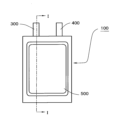
- FIGS. 2 and 3 are diagrams showing schematic diagrams of other examples of the all-solid-state secondary battery of the present invention.
- FIG. 2 is a plan view of the all-solid-state secondary battery
- FIG. 3 is a cross-sectional view taken along line I-I in FIG. 2.
- the all-solid-state secondary battery 100 shown in Figures 2 and 3 houses the electrode body 200 inside a laminate film exterior body 500 made of two sheets of metal laminate film, and the laminate film exterior body 500 is sealed at its outer periphery by heat fusing the upper and lower metal laminate films.
- the electrode body 200 is constructed by stacking a positive electrode, a negative electrode, and a solid electrolyte layer interposed between them.
- FIG. 3 does not distinguish between the layers that make up the laminate film exterior body 500 and the components (positive electrode, negative electrode, etc.) that make up the electrode body 200.
- the positive electrode of the electrode body 200 is connected to the positive electrode external terminal 300 within the battery 100, and although not shown, the negative electrode of the electrode body 200 is also connected to the negative electrode external terminal 400 within the battery 100.
- One end of the positive electrode external terminal 300 and the negative electrode external terminal 400 is extended to the outside of the laminate film exterior body 500 so that they can be connected to external devices, etc.
- the electrode of the present invention can be used as the positive electrode of the all-solid-state secondary battery, but when the negative electrode is the electrode of the present invention, a positive electrode other than the electrode of the present invention can also be used.
- the positive electrode other than the electrode of the present invention include a positive electrode having the same configuration as the electrode of the present invention except that it contains an electrode active material whose D 90 does not satisfy the above value, and a positive electrode having the same configuration as the electrode of the present invention except that the B/A value does not satisfy the above value.
- the electrode of the present invention can be used as the negative electrode of the all-solid-state secondary battery, but when the positive electrode is the electrode of the present invention, a negative electrode other than the electrode of the present invention can also be used.
- the negative electrode other than the electrode of the present invention include a negative electrode having the same configuration as the electrode of the present invention except that it contains an electrode active material whose D 90 does not satisfy the above value, a negative electrode having the same configuration as the electrode of the present invention except that the B/A value does not satisfy the above value, and a negative electrode having a lithium sheet or a lithium alloy sheet.
- negative electrodes having lithium or lithium alloy sheets those consisting of these sheets alone or those consisting of these sheets bonded to a current collector are used.
- Alloying elements for lithium alloys include aluminum, lead, bismuth, indium, and gallium, with aluminum and indium being preferred.
- the proportion of alloying elements in the lithium alloy is preferably 50 atomic % or less (in this case, the remainder is lithium and unavoidable impurities).
- a laminate in which a layer containing an alloying element for forming a lithium alloy is laminated on the surface of a lithium layer (layer containing lithium) composed of metallic lithium foil or the like, for example by pressing the layer, and the laminate is brought into contact with a solid electrolyte in a battery to form a lithium alloy on the surface of the lithium layer, thereby forming a negative electrode.
- a laminate having a layer containing an alloying element on only one side of the lithium layer may be used, or a laminate having layers containing an alloying element on both sides of the lithium layer may be used.
- the laminate can be formed, for example, by pressing metallic lithium foil and a foil composed of an alloying element.
- the current collector can also be used when a lithium alloy is formed in a battery to form a negative electrode, and for example, a laminate having a lithium layer on one side of the negative electrode current collector and a layer containing an alloying element on the side of the lithium layer opposite the negative electrode current collector may be used, or a laminate having lithium layers on both sides of the negative electrode current collector and each lithium layer having a layer containing an alloying element on the side opposite the negative electrode current collector may be used.
- the negative electrode current collector and the lithium layer may be laminated by compression bonding or the like.
- the layer containing the alloying elements in the laminate to be used as the negative electrode can be, for example, a foil composed of these alloying elements.
- the thickness of the layer containing the alloying elements is preferably 1 ⁇ m or more, more preferably 3 ⁇ m or more, and is preferably 20 ⁇ m or less, and more preferably 12 ⁇ m or less.
- the lithium layer of the laminate to be used as the negative electrode can be, for example, metallic lithium foil.
- the thickness of the lithium layer is preferably 0.1 to 1.5 mm.
- the thickness of the sheet for the negative electrode having a lithium or lithium alloy sheet is also preferably 0.1 to 1.5 mm.
- the current collector can be the same as the current collectors exemplified above as those usable when the electrode of the present invention is the negative electrode.
- the solid electrolyte in the solid electrolyte layer interposed between the positive electrode and the negative electrode can be one or more of the various sulfide-based solid electrolytes, hydride-based solid electrolytes, halide-based solid electrolytes, and oxide-based solid electrolytes exemplified above as those usable for the electrodes.
- a sulfide-based solid electrolyte in all of the positive electrode, negative electrode, and solid electrolyte layer, and it is even more preferable to contain an Argyrodite-type sulfide-based solid electrolyte.
- the solid electrolyte layer may have a porous body such as a resin nonwoven fabric as a support.
- the solid electrolyte layer can be formed by compressing the solid electrolyte by pressure molding or the like; by applying a composition for forming the solid electrolyte layer, which is prepared by dispersing the solid electrolyte in a solvent, onto a substrate (including a porous body serving as a support), a positive electrode, or a negative electrode, drying the composition, and, if necessary, performing pressure molding such as pressing.
- the solvent used in the composition for forming the solid electrolyte layer should be one that is unlikely to deteriorate the solid electrolyte, and it is preferable to use the same solvents as those exemplified above for the electrode mixture-containing composition.
- the thickness of the solid electrolyte layer is preferably 10 to 500 ⁇ m.
- the positive electrode and the negative electrode can be used in a battery in the form of a laminated electrode body in which the positive electrode and the negative electrode are laminated with a solid electrolyte layer interposed therebetween, or in the form of a wound electrode body in which this laminated electrode body is wound.
- the electrode body When forming the electrode body, it is preferable to pressure mold the positive electrode, negative electrode, and solid electrolyte layer in a stacked state in order to increase the mechanical strength of the electrode body.
- the form of the all-solid-state secondary battery may be one having an exterior body composed of an exterior can, a sealing can, and a gasket as shown in FIG. 1, that is, one generally called a coin-type battery or a button-type battery, or one having an exterior body composed of a resin film or a metal-resin laminate film as shown in FIGS. 2 and 3, or one having an exterior body having a metallic, bottomed, tubular (cylindrical or rectangular) exterior can and a sealing structure that seals the opening of the can.
- Example 1 Preparation of Positive Electrode> 0.86g of lithium and 38.7g of pentaethoxyniobium were mixed in 394g of dehydrated ethanol to prepare a coating solution for forming a reaction suppression layer. Next, the coating solution for forming a reaction suppression layer was applied to 1000g of a positive electrode active material (LiCoO 2 ) at a rate of 2g per minute using a coating device using a rolling fluidized bed. The obtained powder was heat-treated at 350°C to obtain a positive electrode material having a reaction suppression layer formed on the surface thereof, which is composed of 2 parts by mass of LiNbO 3 per 100 parts by mass of the positive electrode active material.
- a positive electrode active material LiCoO 2
- the positive electrode material, vapor-grown carbon fiber (conductive assistant), and Li 6 PS 5 Cl (sulfide-based solid electrolyte) were mixed to prepare a positive electrode mixture.
- the mixture ratio of the positive electrode material, conductive assistant, and sulfide-based solid electrolyte was 66:4:30 by mass ratio.
- 112 mg of this positive electrode mixture was put into a powder molding die having a diameter of 7.5 mm, and molding was performed at a pressure of 6000 kgf/cm 2 using a press machine to produce a positive electrode consisting of a cylindrical positive electrode mixture compact.
- the active material was synthesized by a solid-state reaction method using various metal oxide powders (all obtained from Kojundo Chemical Co., Ltd.) as starting materials. 96.72 g, 2.34 g, and 1.04 g of Nb 2 O 5 (purity: >99.9%) with an average particle size of 1 ⁇ m, ⁇ -Al 2 O 3 (purity: >99.99%) with an average particle size of 1 ⁇ m, and CuO (purity: >99.99%) were weighed and mixed, respectively.
- the mixture of the starting materials was added to a zirconia container with a capacity of 500 ml together with 70 g of ethanol and 300 g of YSZ balls with a diameter of 2 mm, and mixed for 6 hours under the condition of 300 rpm in a planetary ball mill [Fritsch "planetary mill pulverisette 5" (trade name)], and the slurry obtained by separating the zirconia balls from the sample after the mixing process was dried to obtain a precursor powder of the negative electrode active material.
- the precursor powder was transferred to an alumina crucible, heated to 900 ° C. at a heating rate of 16 ° C. / min in an air atmosphere, and then kept as it was for 8 hours to be fired, and naturally cooled to room temperature.
- the obtained powder was crushed in a mortar for 5 minutes, and passed through a sieve with an opening of 150 ⁇ m to obtain a crude product of the active material.
- 4 g of the crude product of the active material was added to a zirconia container with an internal volume of 12.5 ml together with 4 g of ethanol and 30 g of YSZ balls with a diameter of 2 mm, and the mixture was crushed for 6 hours at 300 rpm in the planetary ball mill.
- the obtained slurry was dried overnight at 60° C. under reduced pressure to obtain particles of Cu 0.2 Al 0.74 Nb 11.05 O 27.89 , which is the negative electrode active material.
- the powder XRD pattern of the obtained negative electrode active material was measured, and it was confirmed that the negative electrode active material had a monoclinic crystal structure and belonged to the C2/m space group.
- the negative electrode active material, graphene (conductive assistant), and sulfide-based solid electrolyte (Li 6 PS 5 Cl) were mixed in a mass ratio of 69:6.1:24.9, and kneaded for 1 hour in an automatic mortar [manufactured by Fritsch, "Motor Grinder P-2" (trade name)] in an argon atmosphere to prepare a negative electrode mixture.
- 62 mg of the negative electrode mixture was poured onto the solid electrolyte layer in the powder molding die, and molding was performed at a pressure of 14,000 kgf / cm 2 using a press machine, and a negative electrode composed of a negative electrode mixture molded body was formed on the solid electrolyte layer, thereby producing a laminated electrode body in which a positive electrode, a solid electrolyte layer, and a negative electrode were laminated.
- the D 90 and D 50 (A value) of the negative electrode active material were 0.67 ⁇ m and 0.46 ⁇ m, respectively, the D 50 (B value) of the conductive assistant was 0.55 ⁇ m, and the B/A value was 1.20.
- the aspect ratio of the cross section of the conductive assistant in the negative electrode was 2.6.
- the crystallite size d in the b-axis direction of the negative electrode active material was 81 nm, and the d/A value was 0.18.
- the laminated electrode body was placed on top of the graphite sheet with the negative electrode facing the graphite sheet side, another sheet of the graphite sheet was placed on top of that, and a stainless steel outer can was then placed over it, after which the open end of the outer can was crimped inward to seal, thereby producing a flat all-solid-state secondary battery with a diameter of approximately 9 mm in which the graphite sheet was placed between the inner bottom surface of the sealing can and the laminated electrode body, and between the inner bottom surface of the outer can and the laminated electrode body, respectively.
- Example 2 A negative electrode active material was prepared in the same manner as in Example 1 except that the baking temperature of the negative electrode active material was changed to 950° C., and a flat all-solid-state secondary battery was prepared in the same manner as in Example 1 except that this negative electrode active material was used.
- the D 90 and D 50 (A value) of the negative electrode active material were 0.77 ⁇ m and 0.49 ⁇ m, respectively, the D 50 (B value) of the conductive additive was 0.52 ⁇ m, and the B/A value was 1.06.
- the cross-sectional aspect ratio of the conductive additive in the negative electrode was 2.7.
- the crystallite size d in the b-axis direction of the negative electrode active material was 78 nm, and the d/A value was 0.16.
- Example 3 The size of the YSZ balls added when mixing the mixture of starting materials was 5 mm in diameter, the conditions for mixing the mixture of starting materials were 250 rpm for 3 hours, and the firing conditions were holding at 1000 ° C. for 4 hours.
- the size of the YSZ balls added when crushing the crude product was 5 mm in diameter, and the conditions for crushing the crude product were 250 rpm for 3 hours.
- a flat all-solid-state secondary battery was produced in the same manner as in Example 1, except that this negative electrode mixture was used.
- the D 90 and D 50 (A value) of the negative electrode active material were 1.23 ⁇ m and 0.75 ⁇ m, respectively, the D 50 (B value) of the conductive additive was 0.33 ⁇ m, and the B/A value was 0.44.
- the cross-sectional aspect ratio of the conductive additive in the negative electrode was 2.8.
- the crystallite size d in the b-axis direction of the negative electrode active material was 97 nm, and the d/A value was 0.13.
- Comparative Example 1 A negative electrode mixture was prepared in the same manner as in Example 3 except that the time for mixing the negative electrode active material, the solid electrolyte, and the graphene was changed to 20 minutes, and a flat all-solid-state secondary battery was produced in the same manner as in Example 1 except that this negative electrode mixture was used.
- the D 90 and D 50 (A value) of the negative electrode active material were 2.40 ⁇ m and 1.01 ⁇ m, respectively, the D 50 (B value) of the conductive additive was 3.99 ⁇ m, and the B/A value was 3.95.
- the aspect ratio of the cross section of the conductive additive in the negative electrode was 3.3.
- the crystallite size d in the b-axis direction of the negative electrode active material was 97 nm, and the d/A value was 0.10.
- a flat all-solid-state secondary battery was fabricated in the same manner as in Example 1 except that this negative electrode mixture was used.
- the D 90 and D 50 (A value) of the negative electrode active material were 1.38 ⁇ m and 0.78 ⁇ m, respectively, the D 50 (B value) of the conductive additive was 1.44 ⁇ m, and the B/A value was 1.85.
- the cross-sectional aspect ratio of the conductive additive in the negative electrode was 2.6.
- the crystallite size d in the b-axis direction of the negative electrode active material was 97 nm, and the d/A value was 0.12.
- the impedance of the flat all-solid-state secondary batteries of the examples and comparative examples was measured by the following method to evaluate the internal resistance.
- Each battery was charged at a constant current of 0.04 C until the voltage reached 3.2 V, then charged at a constant voltage of 0.01 C until the current reached 0.01 C, and then discharged at a constant current of 0.04 C until the voltage reached 1.0 V. Thereafter, each battery was charged at a constant current under the same conditions as above until the capacity reached 5 mAh, and the open circuit voltage was measured for 10 minutes. In this state, the impedance was measured at 1 Hz with an effective AC voltage of 10 mV.
- the output characteristics of the battery were evaluated by calculating the ratio of the 0.05C discharge capacity (0.05C/0.01C discharge capacity maintenance rate) when the 0.01C discharge capacity was set to 100%.
- the flat all-solid-state secondary batteries of Examples 1 to 3 having negative electrodes with appropriate D 90 and B/A values of the negative electrode active material had lower impedance and reduced internal resistance than the batteries of Comparative Examples 1 and 2 having inappropriate values.
- the all-solid-state secondary battery of the present invention has low internal resistance and excellent characteristics, and can be used preferably in applications requiring such characteristics. It can also be applied to other applications in which conventionally known all-solid-state secondary batteries are used.
- the electrode for the all-solid-state secondary battery of the present invention can constitute the all-solid-state secondary battery of the present invention.
- Reference Signs List 1 100 All-solid-state secondary battery 10 Positive electrode 20 Negative electrode 30 Solid electrolyte layer 40 Outer can 50 Sealing can 60 Gasket 200 Electrode body 300 Positive electrode external terminal 400 Negative electrode external terminal 500 Laminate film outer case
Landscapes
- Chemical & Material Sciences (AREA)
- Chemical Kinetics & Catalysis (AREA)
- Electrochemistry (AREA)
- General Chemical & Material Sciences (AREA)
- Engineering & Computer Science (AREA)
- Manufacturing & Machinery (AREA)
- Inorganic Chemistry (AREA)
- Materials Engineering (AREA)
- Physics & Mathematics (AREA)
- Condensed Matter Physics & Semiconductors (AREA)
- General Physics & Mathematics (AREA)
- Battery Electrode And Active Subsutance (AREA)
Priority Applications (4)
| Application Number | Priority Date | Filing Date | Title |
|---|---|---|---|
| KR1020257024503A KR20250123212A (ko) | 2023-01-25 | 2023-12-27 | 전고체 이차 전지용 전극 및 전고체 이차 전지 |
| EP23918679.4A EP4657537A4 (en) | 2023-01-25 | 2023-12-27 | Electrode for all-solid-state secondary batteries and all-solid-state secondary battery |
| JP2024572923A JPWO2024157725A1 (https=) | 2023-01-25 | 2023-12-27 | |
| CN202380092183.1A CN120584411A (zh) | 2023-01-25 | 2023-12-27 | 全固体二次电池用电极以及全固体二次电池 |
Applications Claiming Priority (2)
| Application Number | Priority Date | Filing Date | Title |
|---|---|---|---|
| JP2023-009120 | 2023-01-25 | ||
| JP2023009120 | 2023-01-25 |
Publications (1)
| Publication Number | Publication Date |
|---|---|
| WO2024157725A1 true WO2024157725A1 (ja) | 2024-08-02 |
Family
ID=91970455
Family Applications (1)
| Application Number | Title | Priority Date | Filing Date |
|---|---|---|---|
| PCT/JP2023/046862 Ceased WO2024157725A1 (ja) | 2023-01-25 | 2023-12-27 | 全固体二次電池用電極および全固体二次電池 |
Country Status (5)
| Country | Link |
|---|---|
| EP (1) | EP4657537A4 (https=) |
| JP (1) | JPWO2024157725A1 (https=) |
| KR (1) | KR20250123212A (https=) |
| CN (1) | CN120584411A (https=) |
| WO (1) | WO2024157725A1 (https=) |
Cited By (1)
| Publication number | Priority date | Publication date | Assignee | Title |
|---|---|---|---|---|
| WO2025204950A1 (ja) * | 2024-03-29 | 2025-10-02 | Ube株式会社 | 遷移金属複合酸化物粉末、それを用いた電極、及び非水電解質蓄電デバイス |
Citations (8)
| Publication number | Priority date | Publication date | Assignee | Title |
|---|---|---|---|---|
| JPH10199507A (ja) | 1997-01-16 | 1998-07-31 | Asahi Chem Ind Co Ltd | リチウム二次電池用電極 |
| JP2006172995A (ja) * | 2004-12-17 | 2006-06-29 | Nissan Motor Co Ltd | 電極インクおよび電池 |
| JP2013033641A (ja) | 2011-08-02 | 2013-02-14 | Hitachi Maxell Energy Ltd | 非水二次電池用電極及び非水二次電池 |
| JP2019169399A (ja) * | 2018-03-26 | 2019-10-03 | 株式会社東芝 | 活物質、活物質複合材料、電極、二次電池、電池パック及び車両 |
| WO2020070958A1 (ja) | 2018-10-01 | 2020-04-09 | パナソニックIpマネジメント株式会社 | ハロゲン化物固体電解質材料およびこれを用いた電池 |
| WO2020070955A1 (ja) | 2018-10-01 | 2020-04-09 | パナソニックIpマネジメント株式会社 | ハロゲン化物固体電解質材料およびこれを用いた電池 |
| JP2021044195A (ja) | 2019-09-13 | 2021-03-18 | Tdk株式会社 | リチウムイオン二次電池用負極及びリチウムイオン二次電池 |
| JP2021114407A (ja) * | 2020-01-17 | 2021-08-05 | 住友化学株式会社 | 全固体リチウムイオン電池用混合粉末、全固体リチウムイオン電池用混合ペースト、電極および全固体リチウムイオン電池 |
Family Cites Families (3)
| Publication number | Priority date | Publication date | Assignee | Title |
|---|---|---|---|---|
| KR101773698B1 (ko) * | 2015-01-13 | 2017-08-31 | 주식회사 엘지화학 | 리튬 이차전지의 양극 형성용 조성물의 제조방법, 및 이를 이용하여 제조한 양극 및 리튬 이차전지 |
| EP4292984B1 (en) * | 2021-03-11 | 2026-01-14 | Maxell, Ltd. | Electrode active material for electrochemical elements, electrode material for electrochemical elements, electrode for electrochemical elements, electrochemical element, and mobile object |
| JP2022176525A (ja) * | 2021-05-17 | 2022-11-30 | 株式会社日立製作所 | 負極活物質、負極、電池セル |
-
2023
- 2023-12-27 JP JP2024572923A patent/JPWO2024157725A1/ja active Pending
- 2023-12-27 WO PCT/JP2023/046862 patent/WO2024157725A1/ja not_active Ceased
- 2023-12-27 CN CN202380092183.1A patent/CN120584411A/zh active Pending
- 2023-12-27 KR KR1020257024503A patent/KR20250123212A/ko active Pending
- 2023-12-27 EP EP23918679.4A patent/EP4657537A4/en active Pending
Patent Citations (8)
| Publication number | Priority date | Publication date | Assignee | Title |
|---|---|---|---|---|
| JPH10199507A (ja) | 1997-01-16 | 1998-07-31 | Asahi Chem Ind Co Ltd | リチウム二次電池用電極 |
| JP2006172995A (ja) * | 2004-12-17 | 2006-06-29 | Nissan Motor Co Ltd | 電極インクおよび電池 |
| JP2013033641A (ja) | 2011-08-02 | 2013-02-14 | Hitachi Maxell Energy Ltd | 非水二次電池用電極及び非水二次電池 |
| JP2019169399A (ja) * | 2018-03-26 | 2019-10-03 | 株式会社東芝 | 活物質、活物質複合材料、電極、二次電池、電池パック及び車両 |
| WO2020070958A1 (ja) | 2018-10-01 | 2020-04-09 | パナソニックIpマネジメント株式会社 | ハロゲン化物固体電解質材料およびこれを用いた電池 |
| WO2020070955A1 (ja) | 2018-10-01 | 2020-04-09 | パナソニックIpマネジメント株式会社 | ハロゲン化物固体電解質材料およびこれを用いた電池 |
| JP2021044195A (ja) | 2019-09-13 | 2021-03-18 | Tdk株式会社 | リチウムイオン二次電池用負極及びリチウムイオン二次電池 |
| JP2021114407A (ja) * | 2020-01-17 | 2021-08-05 | 住友化学株式会社 | 全固体リチウムイオン電池用混合粉末、全固体リチウムイオン電池用混合ペースト、電極および全固体リチウムイオン電池 |
Cited By (1)
| Publication number | Priority date | Publication date | Assignee | Title |
|---|---|---|---|---|
| WO2025204950A1 (ja) * | 2024-03-29 | 2025-10-02 | Ube株式会社 | 遷移金属複合酸化物粉末、それを用いた電極、及び非水電解質蓄電デバイス |
Also Published As
| Publication number | Publication date |
|---|---|
| KR20250123212A (ko) | 2025-08-14 |
| JPWO2024157725A1 (https=) | 2024-08-02 |
| CN120584411A (zh) | 2025-09-02 |
| EP4657537A4 (en) | 2026-04-29 |
| EP4657537A1 (en) | 2025-12-03 |
Similar Documents
| Publication | Publication Date | Title |
|---|---|---|
| JP7824857B2 (ja) | 電気化学素子用電極活物質およびその製造方法、電気化学素子用電極材料、電気化学素子用電極、電気化学素子、並びに移動体 | |
| JP6963866B2 (ja) | 全固体電池用負極および全固体電池 | |
| CN107210441A (zh) | 非水系电解质二次电池用正极活性物质和其制造方法,以及使用了该正极活性物质的非水系电解质二次电池 | |
| JP2021144906A (ja) | 全固体電池用正極および全固体電池 | |
| JP7401359B2 (ja) | 全固体電池用電極および全固体電池 | |
| WO2019189679A1 (ja) | 非水系電解質二次電池用正極活物質 | |
| US20250219088A1 (en) | All-solid-state battery electrode and all-solid-state battery | |
| EP4292984B1 (en) | Electrode active material for electrochemical elements, electrode material for electrochemical elements, electrode for electrochemical elements, electrochemical element, and mobile object | |
| WO2024157725A1 (ja) | 全固体二次電池用電極および全固体二次電池 | |
| JPWO2024157725A5 (https=) | ||
| CN114258600B (zh) | 作为用于可再充电锂离子电池的正电极活性材料的锂镍锰钴复合氧化物 | |
| US20250201802A1 (en) | Electrode for non-aqueous electrolyte secondary battery, and non-aqueous electrolyte secondary battery | |
| EP4682970A1 (en) | Positive electrode for all-solid-state secondary batteries, and all-solid-state secondary battery | |
| JPWO2024195636A5 (https=) | ||
| CN114365309B (zh) | 全固体电池用电极和全固体电池 | |
| JP7571714B2 (ja) | リチウムイオン二次電池用正極 | |
| JP7657576B2 (ja) | 全固体電池用正極および全固体電池 | |
| EP4369454B1 (en) | All-solid-state battery | |
| WO2025258604A1 (ja) | 全固体二次電池 | |
| WO2024157640A1 (ja) | 固体電池 |
Legal Events
| Date | Code | Title | Description |
|---|---|---|---|
| 121 | Ep: the epo has been informed by wipo that ep was designated in this application |
Ref document number: 23918679 Country of ref document: EP Kind code of ref document: A1 |
|
| WWE | Wipo information: entry into national phase |
Ref document number: 2024572923 Country of ref document: JP |
|
| ENP | Entry into the national phase |
Ref document number: 1020257024503 Country of ref document: KR Free format text: ST27 STATUS EVENT CODE: A-0-1-A10-A15-NAP-PA0105 (AS PROVIDED BY THE NATIONAL OFFICE) |
|
| WWE | Wipo information: entry into national phase |
Ref document number: 1020257024503 Country of ref document: KR |
|
| WWE | Wipo information: entry into national phase |
Ref document number: 202380092183.1 Country of ref document: CN |
|
| WWP | Wipo information: published in national office |
Ref document number: 1020257024503 Country of ref document: KR |
|
| NENP | Non-entry into the national phase |
Ref country code: DE |
|
| WWP | Wipo information: published in national office |
Ref document number: 202380092183.1 Country of ref document: CN |
|
| WWP | Wipo information: published in national office |
Ref document number: 2023918679 Country of ref document: EP |