WO2024157622A1 - 粘着剤層を有する積層フィルムの製造方法 - Google Patents
粘着剤層を有する積層フィルムの製造方法 Download PDFInfo
- Publication number
- WO2024157622A1 WO2024157622A1 PCT/JP2023/043861 JP2023043861W WO2024157622A1 WO 2024157622 A1 WO2024157622 A1 WO 2024157622A1 JP 2023043861 W JP2023043861 W JP 2023043861W WO 2024157622 A1 WO2024157622 A1 WO 2024157622A1
- Authority
- WO
- WIPO (PCT)
- Prior art keywords
- film
- adhesive layer
- cut
- cut groove
- full
- Prior art date
- Legal status (The legal status is an assumption and is not a legal conclusion. Google has not performed a legal analysis and makes no representation as to the accuracy of the status listed.)
- Ceased
Links
Images






Classifications
-
- C—CHEMISTRY; METALLURGY
- C09—DYES; PAINTS; POLISHES; NATURAL RESINS; ADHESIVES; COMPOSITIONS NOT OTHERWISE PROVIDED FOR; APPLICATIONS OF MATERIALS NOT OTHERWISE PROVIDED FOR
- C09J—ADHESIVES; NON-MECHANICAL ASPECTS OF ADHESIVE PROCESSES IN GENERAL; ADHESIVE PROCESSES NOT PROVIDED FOR ELSEWHERE; USE OF MATERIALS AS ADHESIVES
- C09J7/00—Adhesives in the form of films or foils
- C09J7/40—Adhesives in the form of films or foils characterised by release liners
- C09J7/403—Adhesives in the form of films or foils characterised by release liners characterised by the structure of the release feature
-
- B—PERFORMING OPERATIONS; TRANSPORTING
- B23—MACHINE TOOLS; METAL-WORKING NOT OTHERWISE PROVIDED FOR
- B23K—SOLDERING OR UNSOLDERING; WELDING; CLADDING OR PLATING BY SOLDERING OR WELDING; CUTTING BY APPLYING HEAT LOCALLY, e.g. FLAME CUTTING; WORKING BY LASER BEAM
- B23K26/00—Working by laser beam, e.g. welding, cutting or boring
- B23K26/36—Removing material
- B23K26/362—Laser etching
- B23K26/364—Laser etching for making a groove or trench, e.g. for scribing a break initiation groove
-
- B—PERFORMING OPERATIONS; TRANSPORTING
- B23—MACHINE TOOLS; METAL-WORKING NOT OTHERWISE PROVIDED FOR
- B23K—SOLDERING OR UNSOLDERING; WELDING; CLADDING OR PLATING BY SOLDERING OR WELDING; CUTTING BY APPLYING HEAT LOCALLY, e.g. FLAME CUTTING; WORKING BY LASER BEAM
- B23K26/00—Working by laser beam, e.g. welding, cutting or boring
- B23K26/70—Auxiliary operations or equipment
-
- B—PERFORMING OPERATIONS; TRANSPORTING
- B32—LAYERED PRODUCTS
- B32B—LAYERED PRODUCTS, i.e. PRODUCTS BUILT-UP OF STRATA OF FLAT OR NON-FLAT, e.g. CELLULAR OR HONEYCOMB, FORM
- B32B38/00—Ancillary operations in connection with laminating processes
- B32B38/18—Handling of layers or the laminate
-
- C—CHEMISTRY; METALLURGY
- C09—DYES; PAINTS; POLISHES; NATURAL RESINS; ADHESIVES; COMPOSITIONS NOT OTHERWISE PROVIDED FOR; APPLICATIONS OF MATERIALS NOT OTHERWISE PROVIDED FOR
- C09J—ADHESIVES; NON-MECHANICAL ASPECTS OF ADHESIVE PROCESSES IN GENERAL; ADHESIVE PROCESSES NOT PROVIDED FOR ELSEWHERE; USE OF MATERIALS AS ADHESIVES
- C09J201/00—Adhesives based on unspecified macromolecular compounds
-
- C—CHEMISTRY; METALLURGY
- C09—DYES; PAINTS; POLISHES; NATURAL RESINS; ADHESIVES; COMPOSITIONS NOT OTHERWISE PROVIDED FOR; APPLICATIONS OF MATERIALS NOT OTHERWISE PROVIDED FOR
- C09J—ADHESIVES; NON-MECHANICAL ASPECTS OF ADHESIVE PROCESSES IN GENERAL; ADHESIVE PROCESSES NOT PROVIDED FOR ELSEWHERE; USE OF MATERIALS AS ADHESIVES
- C09J7/00—Adhesives in the form of films or foils
- C09J7/10—Adhesives in the form of films or foils without carriers
-
- C—CHEMISTRY; METALLURGY
- C09—DYES; PAINTS; POLISHES; NATURAL RESINS; ADHESIVES; COMPOSITIONS NOT OTHERWISE PROVIDED FOR; APPLICATIONS OF MATERIALS NOT OTHERWISE PROVIDED FOR
- C09J—ADHESIVES; NON-MECHANICAL ASPECTS OF ADHESIVE PROCESSES IN GENERAL; ADHESIVE PROCESSES NOT PROVIDED FOR ELSEWHERE; USE OF MATERIALS AS ADHESIVES
- C09J7/00—Adhesives in the form of films or foils
- C09J7/20—Adhesives in the form of films or foils characterised by their carriers
-
- C—CHEMISTRY; METALLURGY
- C09—DYES; PAINTS; POLISHES; NATURAL RESINS; ADHESIVES; COMPOSITIONS NOT OTHERWISE PROVIDED FOR; APPLICATIONS OF MATERIALS NOT OTHERWISE PROVIDED FOR
- C09J—ADHESIVES; NON-MECHANICAL ASPECTS OF ADHESIVE PROCESSES IN GENERAL; ADHESIVE PROCESSES NOT PROVIDED FOR ELSEWHERE; USE OF MATERIALS AS ADHESIVES
- C09J7/00—Adhesives in the form of films or foils
- C09J7/30—Adhesives in the form of films or foils characterised by the adhesive composition
- C09J7/38—Pressure-sensitive adhesives [PSA]
-
- C—CHEMISTRY; METALLURGY
- C09—DYES; PAINTS; POLISHES; NATURAL RESINS; ADHESIVES; COMPOSITIONS NOT OTHERWISE PROVIDED FOR; APPLICATIONS OF MATERIALS NOT OTHERWISE PROVIDED FOR
- C09J—ADHESIVES; NON-MECHANICAL ASPECTS OF ADHESIVE PROCESSES IN GENERAL; ADHESIVE PROCESSES NOT PROVIDED FOR ELSEWHERE; USE OF MATERIALS AS ADHESIVES
- C09J2301/00—Additional features of adhesives in the form of films or foils
- C09J2301/10—Additional features of adhesives in the form of films or foils characterized by the structural features of the adhesive tape or sheet
Definitions
- the present invention relates to a method for producing a laminated film having an adhesive layer.
- Display panels have a laminated structure that includes elements such as a pixel panel, a polarizing film, a touch panel, and a cover film.
- an optically transparent adhesive sheet (optical adhesive sheet) is used to bond the elements included in the laminated structure.
- the optical adhesive sheet is manufactured, for example, in a form in which both sides of the sheet are covered with release liners (in the form of a laminated film having an adhesive layer).
- a foldable display panel can be repeatedly deformed between a curved shape and a flat, non-bent shape.
- each element in the laminated structure is made to be repeatedly foldable, and a thin optical adhesive sheet is used to bond such elements together.
- Optical adhesive sheets for flexible devices such as foldable display panels are described, for example, in Patent Document 1 below.
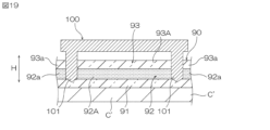
- Optical adhesive sheets for display panels are conventionally manufactured, for example, as follows:
- a work film W' is prepared.
- the work film W' consists of a laminate sheet 90 as a long original sheet, and a long carrier film C' that supports the laminate sheet 90.
- the laminate sheet 90 has a release liner 91, an adhesive layer 92, and a release liner 93, in that order in the thickness direction H.
- the release liner 91 is in releasable contact with one side of the adhesive layer 92.
- the release liner 93 is in releasable contact with the other side of the adhesive layer 92.
- the carrier film C' supports the laminate sheet 90 from the release liner 91 side.
- the adhesive layer 92 of the laminated sheet 90 is pressed to form a plurality of sheet-like adhesive sheets 92A (pressing process).
- the blade 101 of the blade die 100 is pressed into the laminated sheet 90 from the release liner 93 side until it reaches the release liner 91.
- a peripheral portion 92a is formed around the adhesive sheet 92A in the adhesive layer 92.
- the release liner 93 is also pressed to form a release liner 93A of the same shape in plan view as the adhesive layer 92, and a peripheral portion 93a is formed around the release liner 93A. Also, a cutting groove 95 (FIG. 18B) is formed in the laminated sheet 90 from the release liner 93 side to the release liner 91.
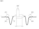
- FIG. 20 shows an example of a conventional press processing process.
- the work film W' flowing on the production line passes between a pair of nip rollers 201, 201, a press processing machine 202, and between a pair of nip rollers 203, 203, in that order.
- the press processing machine 202 is equipped with an intermittent feed device, a processing stage, and a blade mold arranged above the stage (all not shown).
- the work film W' is slackened.
- the work film W' is slackened.
- the work film W' is intermittently fed by the intermittent feed device of the press processing machine 202.
- the unprocessed areas of the workpiece film W' are intermittently supplied onto the processing stage of the press machine 202.
- press processing is performed using a blade die for each unprocessed area of the workpiece film W' that is intermittently supplied.
- the release liner 91A has an extending end 91a that extends outward beyond the edge of the adhesive sheet 92A in the plane direction D perpendicular to the thickness direction H.
- a laminated film 90A equipped with a release liner 91A having such an extending end 91a helps to prevent the adhesive sheet 92A from protruding from the film end.
- Such protruding of the adhesive sheet 92A is undesirable because it can cause the ends of the adhesive sheets 92A of adjacent laminated films 90A to adhere to each other (blocking) when the laminated films 90A are stacked.
- a press processing step (FIG. 18B) is performed on each unprocessed area of the work film W' that is intermittently fed onto the processing stage of the press processing machine 202. That is, the work film W' is alternately transported and stopped in order to process the outer shape of the adhesive sheet.
- an intermittent feeding device is required, and this device must be controlled. This conventional manufacturing method is not preferable from the viewpoint of the manufacturing efficiency of a laminated film having an adhesive layer.
- a removal step (FIG. 18C) is required after the pressing step (FIG. 18B).
- the removal step exposes the release liner 91 between adjacent adhesive sheets 92A on the release liner 91.
- the exposed areas of the release liner 91 are then cut in a cutting step (FIG. 18D) to form a release liner 91A having an extended end 91a.
- the above-mentioned removal step reduces the manufacturing efficiency of a laminated film having an adhesive layer.
- the present invention provides a method for producing a laminated film that is suitable for efficiently producing a laminated film having an adhesive layer.
- the present invention [1] is a method for manufacturing a laminated film having an adhesive layer by a roll-to-roll method, and includes a preparation step of preparing a long work film having a carrier film, a first film layer, an adhesive layer, and a second film layer in this order in the thickness direction, a half-cut step of irradiating and scanning the work film with a first laser light from the second film layer side to melt the second film layer and the adhesive layer to form a half-cut groove, and a full-cut step of irradiating and scanning the work film with a second laser light from the second film layer side to melt the second film layer, the adhesive layer, and the first film layer to form a full-cut groove, in which the half-cut groove and the full-cut groove extend adjacent to each other and in parallel, and are continuous in the extension direction and connected in the adjacent direction.
- the manufacturing method of a laminated film having an adhesive layer includes a half-cut process and a full-cut process, as described above.
- a half-cut groove (from the second film layer side to the first film layer in the work film) is formed by irradiation and scanning with a first laser light.
- a first laser light This results in the contour processing of the adhesive layer and the second film layer. That is, an individualized adhesive layer is formed in the adhesive layer, and an individualized second film is formed in the second film layer.
- a full-cut groove (from the second film layer side to the carrier film in the work film) is formed by irradiation and scanning with a second laser light. This results in the contour processing of the first film layer.
- an individualized first film is formed in the first film layer.
- the half-cut process and the full-cut process are performed in this order, or the full-cut process and the half-cut process are performed in this order, and the half-cut groove and the full-cut groove are formed adjacent to each other.
- the half-cut groove and the full-cut groove extend parallel to each other adjacently, and are continuous in the extension direction and connected to each other in the adjacent direction.
- the portions facing the half-cut groove and the full-cut groove extend outward in a surface direction perpendicular to the thickness direction beyond the edge of the singulated adhesive layer on the first film. Therefore, according to this manufacturing method, it is possible to manufacture a laminated film having an adhesive layer (having a first film, an adhesive layer, and a third film in this order in the thickness direction), in which the first film has an extended end portion.
- the laminated film having an adhesive layer is contoured by laser processing.
- Laser processing is suitable for continuous contour processing while continuously flowing the work film (there is no need to feed the work film intermittently for contour processing). Therefore, this manufacturing method is suitable for efficiently manufacturing laminated films having an adhesive layer.
- the material of the work film is evaporated and removed in the area where the laser light is irradiated onto the work film.
- the material of the work film is evaporated and removed in the area where the laser light is irradiated onto the work film.
- the half-cut groove and the full-cut groove extend adjacent to each other and in parallel, as described above, and are connected continuously in the extension direction in the adjacent direction.
- the half-cut groove and the full-cut groove connected in this way define the outer shape of the laminated film (first film, adhesive, second film) on the carrier film. Therefore, in this manufacturing method, the removal process (the process of removing the surrounding area around the adhesive layer that has been contoured) described above in relation to the conventional manufacturing method is not necessary. Therefore, this manufacturing method is suitable for efficiently manufacturing a laminated film having an adhesive layer.
- this manufacturing method is suitable for efficiently manufacturing a laminated film having an adhesive layer (comprising a first film, an adhesive layer, and a third film in that order in the thickness direction).
- the present invention [2] includes the method for manufacturing a laminated film having an adhesive layer described in [1] above, in which, in the half-cut process, the melting of the second film layer and the adhesive layer by irradiation and scanning with the first laser light is repeated multiple times while shifting the melting point in a direction intersecting the direction of the scanning, thereby forming the half-cut groove.
- Such a half-cut process is preferable for forming wide half-cut grooves.
- the wider the groove width of the half-cut groove the longer the extended end portion of the first film that can be produced.
- the longer the extended end portion the more the above-mentioned blocking can be suppressed.
- the present invention [3] includes a method for producing a laminated film having an adhesive layer as described in [1] or [2] above, which does not include loosening the work film before or after the half-cutting process.
- This manufacturing method does not require adjustments or controls to slacken the work film before and after the half-cut process on the production line, and is preferable for efficiently manufacturing laminated films with adhesive layers.
- the present invention [4] includes a method for producing a laminated film having an adhesive layer as described in [1] to [3] above, which does not include loosening the work film before or after the full cutting process.
- This manufacturing method does not require adjustments or controls to slacken the work film before and after the full cutting process on the production line, and is preferable for efficiently manufacturing laminated films with adhesive layers.
- the present invention [5] includes a method for producing a laminated film having an adhesive layer according to any one of [1] to [4] above, in which the distance between the outer end in the surface direction of the first film layer and the inner end in the surface direction of the adhesive layer in the first film layer and the adhesive layer exposed in the adjacent half-cut groove and full-cut groove is 1 mm or less.
- the area between the outer end in the plane direction of the first film layer exposed in the half-cut groove and the full-cut groove and the inner end in the plane direction of the adhesive layer is part of the edge area that can be used as an alignment mark (edge alignment mark) for detecting the edge of the laminated film being manufactured. Therefore, a configuration in which the distance between the outer end in the plane direction of the first film layer and the inner end in the plane direction of the adhesive layer is 1 mm or less is preferable for suppressing false detection of the edge alignment mark by the detection camera (if the edge alignment mark is too large, false detection will occur).
- the present invention [6] includes a method for manufacturing a laminated film having an adhesive layer according to any one of [1] to [5] above, in which the first half-cut groove, the full-cut groove, and the second half-cut groove are formed adjacent to each other in this order in the longitudinal direction of the work film, and the separation distance between adjacent adhesive layers in the longitudinal direction via the first half-cut groove, the full-cut groove, and the second half-cut groove is 2 mm or less.
- This type of configuration is preferable for achieving high productivity of laminated films.
- the present invention [7] includes a method for producing a laminated film having a pressure-sensitive adhesive layer according to any one of [1] to [6] above, in which the first laser light is a Gaussian laser light or a top-hat laser light.
- This configuration is preferable for properly forming half-cut grooves during the half-cut process.
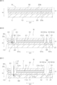
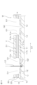
- FIG. 1A, 1B, and 1C are process diagrams of a first embodiment of a laminated film manufacturing method of the present invention, in which Fig. 1A shows a preparation process, Fig. 1B shows a half-cut process, and Fig. 1C shows a full-cut process.
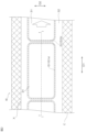
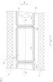
- FIG. 1B is a schematic plan view of an example of a region in a workpiece film after a half-cut process.
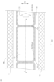
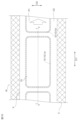
- 1C is a schematic plan view of an example of a region in the work film after the full cutting process (FIG. 1C).
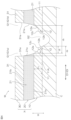
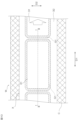
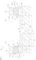
- FIG. FIG. 1C is a partially enlarged cross-sectional view of the work film after the full cut process.
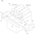
- FIG. 2 is a perspective view of a laser processing device that performs a half-cut process and a full-cut process.
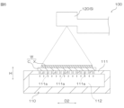
- FIG. 6 is a cross-sectional view of the laser processing apparatus shown in FIG. 5 .
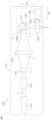
- FIG. 2 is a schematic diagram of an internal configuration of a laser processing unit.
- FIG. 1 is a perspective view of an example of a galvanometer scanner. 1 shows a modified example of the half-cut process, in which the melt-cutting of the second film layer and the pressure-sensitive adhesive layer by irradiation and scanning with the first laser light is repeated multiple times while shifting the melt-cutting location in a direction intersecting the scanning direction, thereby forming a half-cut groove.
- 10 is a schematic plan view of an example of a region in the work film after the half-cut process shown in FIG. 9 .
- FIG. This shows a full-cut process after the half-cut process shown in FIG.
- FIG. 12 is a schematic plan view of an example of an area of the work film after the full cutting process shown in FIG. 11 .
- FIG. 12 is a partially enlarged cross-sectional view of the work film after the full cut process shown in FIG. 11 .
- 14A and 14B are process diagrams of a modified example of the laminated film manufacturing method of the present invention, in which Fig. 14A shows a full-cut process and Fig. 14B shows a half-cut process.
- 15A, 15B, and 15C are process diagrams of a second embodiment of a laminated film manufacturing method of the present invention, in which Fig. 15A shows a preparation process, Fig. 15B shows a half-cut process, and Fig. 15C shows a full-cut process.
- FIG. 15A shows a preparation process
- Fig. 15B shows a half-cut process
- Fig. 15C shows a full-cut process.
- FIG. 15A shows a preparation process
- Fig. 15B shows a half
- FIG. 15B is a schematic plan view of an example of a region in the work film after the half-cut process.
- a schematic plan view of an example of an area in the work film after the full cutting process ( Figure 15C).
- Fig. 18 shows an example of a conventional method for manufacturing a laminated film having an adhesive layer, in which Fig. 18A shows a process for preparing a work film, Fig. 18B shows a pressing process, Fig. 18C shows a removing process, and Fig. 18D shows a cutting process. This shows the press processing process using a blade die. 1 shows an example of a conventional press working process.
- the laminated film manufacturing method according to the first embodiment of the present invention is a roll-to-roll method for manufacturing a sheet-shaped laminated film having an adhesive layer. As shown in Figures 1A to 1C, this manufacturing method includes a preparation process (Figure 1A), a half-cut process (Figure 1B), and a full-cut process (Figure 1C).
- a long work film W is prepared.
- the work film W includes a laminate film X and a carrier film C.
- the laminate film X is a long original film.
- the carrier film C supports the laminate film X.
- the laminated film X comprises a film layer 10 (first film layer), an adhesive layer 20, and a film layer 30 (second film layer) in this order in the thickness direction H.
- the adhesive layer 20 has a first surface 20a and a second surface 20b opposite the first surface 20a.
- the film layer 10 is in contact with the first surface 20a.
- the film layer 30 is in contact with the second surface 20b.
- the laminated film X extends in a planar direction perpendicular to the thickness direction H.
- the carrier film C is a single-sided adhesive film having an adhesive surface on one side in the thickness direction H.
- the adhesive surface of the carrier film C is bonded to the film layer 10 side of the laminated film X. That is, the work film W specifically comprises the carrier film C, the film layer 10, the adhesive layer 20, and the film layer 30, in this order in the thickness direction H.
- the carrier film C is wider than the laminate film X in the width direction D2 (FIGS. 2 and 3) perpendicular to the flow direction D1 of the work film W.
- the laminate film X is disposed at the center position in the width direction D2 on the carrier film C.
- the width (length in the width direction D2) of the laminate film X is, for example, 200 mm or more, preferably 280 mm or more, more preferably 400 mm or more, and is, for example, 2000 mm or less, preferably 1800 mm or less, more preferably 1600 mm or less.
- Such a work film W is run through the production line.
- the film layer 10 is a release liner.
- materials for the release liner include polyester, polyolefin, and polycarbonate.
- polyester include polyethylene terephthalate, polyethylene naphthalate, and polybutylene terephthalate.
- polyolefin include polyethylene, polypropylene, and cycloolefin polymer (COP).
- the film layer 10 as a release liner is in peelable contact with the first surface 20a of the adhesive layer 20.
- the surface of such a film layer 10 (the surface on the adhesive layer 20 side) is preferably subjected to a release treatment.
- the release treatment include a silicone release treatment and a fluorine release treatment.
- the thickness of the film layer 10 is preferably 10 ⁇ m or more, more preferably 15 ⁇ m or more, and even more preferably 20 ⁇ m or more. From the viewpoint of making the laminated film X thinner, the thickness of the film layer 10 is preferably 150 ⁇ m or less, more preferably 120 ⁇ m or less, and even more preferably 100 ⁇ m or less.
- the adhesive layer 20 is formed from an adhesive composition.
- the adhesive composition includes a base polymer.
- the base polymer is an adhesive component that exhibits adhesiveness.
- Examples of base polymers include acrylic polymers, polyurethane polymers, polyamide polymers, and polyvinyl ether polymers.
- the base polymers may be used alone or in combination of two or more types. From the viewpoint of ensuring good transparency and adhesiveness in the adhesive layer 20, an acrylic polymer is preferably used as the base polymer.
- An acrylic polymer is a polymer of monomer components containing 50% or more by mass of (meth)acrylic acid ester.
- “(Meth)acrylic” means acrylic and/or methacrylic.
- the monomer component may contain a copolymerizable monomer that is copolymerizable with the (meth)acrylic acid alkyl ester. Examples of the copolymerizable monomer include a hydroxyl group-containing monomer, a carboxyl group-containing monomer, and a monomer having a nitrogen atom-containing ring.
- the haze of the adhesive layer 20 is preferably 3% or less, more preferably 2% or less, and even more preferably 1% or less.
- the haze of the adhesive layer 20 can be measured using a haze meter in accordance with JIS K7136 (2000). Examples of haze meters include the "NDH2000” manufactured by Nippon Denshoku Industries Co., Ltd. and the “HM-150” manufactured by Murakami Color Research Laboratory Co., Ltd.
- the shear storage modulus of the adhesive layer 20 at 25°C is preferably 10 kPa or more, more preferably 15 kPa or more, even more preferably 20 kPa or more, and particularly preferably 25 kPa or more, from the viewpoint of ensuring the cohesive force of the adhesive layer 20.
- the shear storage modulus of the adhesive layer 20 at 25°C is, for example, 100 kPa or less, preferably 80 kPa or less, more preferably 70 kPa or less, even more preferably 60 kPa or less, and particularly preferably 50 kPa or less, from the viewpoint of realizing the softness required for an optical adhesive sheet for flexible device use in the adhesive layer 20.
- Examples of methods for adjusting the shear storage modulus include selecting the type of base polymer in the adhesive layer 20, adjusting the molecular weight, adjusting the amount of the base polymer, adjusting the glass transition temperature, and adjusting the degree of crosslinking. Examples of methods for adjusting the shear storage modulus include selecting components other than the base polymer in the adhesive layer 20 and adjusting the amount of the base polymer.
- the shear storage modulus of the adhesive layer is determined by dynamic viscoelasticity measurement. The measurement can be performed using the Advanced Rheometric Expansion System (ARES), a dynamic viscoelasticity measuring device manufactured by Rheometric Scientific.
- the measurement mode is shear mode, the measurement temperature range is -40°C to 100°C, the heating rate is 5°C/min, and the frequency is 1Hz.
- the film layer 30 is, for example, a release liner, a functional optical film, or a substrate film (support film).
- the film layer 30 as a release liner is in peelable contact with the second surface 20b of the adhesive layer 20.
- the surface of such a film layer 30 (the surface on the adhesive layer 20 side) is preferably subjected to a release treatment.
- the release treatment include a silicone release treatment and a fluorine release treatment.
- the thickness of the film layer 30 as a release liner is preferably 10 ⁇ m or more, more preferably 15 ⁇ m or more, and even more preferably 20 ⁇ m or more.
- the thickness of the film layer 30 as a release liner is preferably 150 ⁇ m or less, more preferably 120 ⁇ m or less, and even more preferably 100 ⁇ m or less.
- Examples of functional optical films include polarizing films and phase difference films.
- the functional optical film may be other optical films such as panel reinforcement materials.
- the film layer 30 is a functional optical film
- the second surface 20b of the adhesive layer 20 is bonded to such a film layer 30.
- the film layer 30 as a functional optical film and the adhesive layer 20 form a functional optical film with an adhesive layer.
- the polarizing film may be, for example, a hydrophilic polymer film that has been dyed with a dichroic substance and then stretched.
- the dichroic substance may be, for example, iodine and a dichroic dye.
- the hydrophilic polymer film may be, for example, a polyvinyl alcohol (PVA) film, a partially formalized PVA film, and a partially saponified film of an ethylene-vinyl acetate copolymer.
- PVA polyvinyl alcohol
- the polarizing film may also be a polyene-oriented film. Examples of materials for the polyene-oriented film include a dehydrated PVA film and a dehydrochlorinated polyvinyl chloride film.
- the polarizing film may have a protective film bonded to one side and/or the other side in the thickness direction via an adhesive.
- the thickness of the polarizing film is preferably 10 ⁇ m or more, more preferably 20 ⁇ m or more, from the viewpoint of ensuring the function, strength, and durability of the polarizing film.
- the thickness of the polarizing film is preferably 500 ⁇ m or less, more preferably 300 ⁇ m or less, from the viewpoint of making the laminated film X thinner.
- the retardation film may be, for example, a ⁇ /2 wavelength film, a ⁇ /4 wavelength film, or a viewing angle compensation film.
- the retardation film may be made of a polymer film that has been birefringent by stretching.
- the polymer film may be, for example, a cellulose film or a polyester film.
- the cellulose film may be, for example, a triacetyl cellulose film.
- the polyester film may be, for example, a polyethylene terephthalate film, a polyethylene naphthalate film, or a polybutylene terephthalate film.
- the retardation film may be a film having a substrate such as a cellulose film and an orientation layer on the substrate.
- the orientation layer is formed from a liquid crystal compound such as a liquid crystal polymer.
- the thickness of the retardation film is preferably 1 ⁇ m or more, more preferably 2 ⁇ m or more, from the viewpoint of ensuring the function and strength of the retardation film.
- the thickness of the retardation film is preferably 100 ⁇ m or less, more preferably 80 ⁇ m or less, from the viewpoint of making the laminated film X thinner.
- Materials for the base film include, for example, the materials mentioned above as the materials for the release liner.
- the film layer 30 is a base film
- the second surface 20b of the adhesive layer 20 is bonded to such a film layer 30.
- the film layer 30 as a base film and the adhesive layer 20 form, for example, a one-sided adhesive sheet.
- the film layer 30 as a base film and the adhesive layer 20 may form a surface protection film with an adhesive layer.
- the thickness of the base film is preferably 10 ⁇ m or more, more preferably 20 ⁇ m or more, and even more preferably 30 ⁇ m or more.
- the thickness of the base film is preferably 200 ⁇ m or less, more preferably 150 ⁇ m or less, and even more preferably 100 ⁇ m or less.
- the laminated film X can be manufactured, for example, as follows. First, the above-mentioned adhesive composition is applied onto the film layer 30 to form a coating film. Next, the film layer 10 is laminated onto the coating film on the film layer 30. Next, the coating film between the film layers 10 and 30 is dried, and the coating film is irradiated with light as necessary. In this way, the adhesive layer 20 is formed between the film layers 10 and 30. Examples of methods for applying the adhesive composition include roll coating, kiss roll coating, gravure coating, reverse coating, roll brushing, spray coating, dip roll coating, bar coating, knife coating, air knife coating, curtain coating, lip coating, and die coating. The drying temperature for the coating film is, for example, 50°C to 200°C. The drying time is, for example, 5 seconds to 20 minutes.
- a half-cut groove G1 is formed by laser processing the work film W.
- a laser processing device irradiates and scans the work film W with laser light L1 (first laser light) from the film layer 30 side, thereby melting the film layer 30 and the adhesive layer 20 in the laminated film X to form a half-cut groove G1.
- the half-cut groove G1 is formed so as to follow a predetermined processing planned line (designed cutting line) in the work film W.
- a predetermined processing planned line designed cutting line
- FIG. 2 is a plan view that shows a schematic example of an area in the work film W after the half-cut process. In FIG. 2, the half-cut groove G1 is shown with hatching.
- the partial cross-sectional view shown in FIG. 1B corresponds to the partial cross-sectional view taken along line I-I in the work film W shown in FIG. 2.
- Examples of lasers for laser processing include gas lasers, solid-state lasers, and semiconductor lasers.
- Examples of gas lasers include excimer lasers and CO2 lasers (10.6 ⁇ m) (numbers in parentheses indicate laser wavelengths. The same applies below for lasers).
- Examples of excimer lasers include F2 excimer lasers (157 nm), ArF excimer lasers (193 nm), KrF excimer lasers (248 nm), and XeCl excimer lasers (308 nm).
- Examples of solid-state lasers include Nd:YAG lasers (1064 nm), the second harmonic of Nd:YAG lasers (532 nm), the third harmonic of Nd:YAG lasers (355 nm), and the fourth harmonic of Nd:YAG lasers (266 nm).
- Examples of semiconductor lasers include semiconductor lasers with a wavelength of 405 nm.
- a CO2 laser is preferred from the viewpoint of appropriately cutting both the adhesive layer 20 and the film layer 30 which are made of different materials and have different optical properties (such as absorbance).
- the laser light L1 is preferably a Gaussian type laser light or a top hat type laser light. Such a configuration is preferable for appropriately forming the half cut groove G1 in the half cut process.
- a Gaussian type laser light is a laser light whose energy intensity distribution is a Gaussian distribution.
- a top hat type laser light is a laser light whose energy intensity distribution is in a top hat shape.
- the output of the laser light L1 is, for example, 2 to 500 W.
- the pulse frequency of the laser light L1 is, for example, 10 to 30 kHz.
- the spot diameter of the laser light L1 on the work film W is, for example, 50 to 500 ⁇ m.
- a full-cut groove G2 is formed by laser processing the work film W. Specifically, a laser processing device irradiates and scans the work film W with laser light L2 (second laser light) from the film layer 30 side, thereby melting the film layer 30, the adhesive layer 20, and the film layer 10 in the laminated film X to form the full-cut groove G2.
- the full-cut groove G2 is formed along the half-cut groove G1 as shown in FIG. 3 (in FIG. 3, the full-cut groove G2 is shown with finer hatching than the half-cut groove G1).
- the partial cross-sectional view shown in FIG. 1C corresponds to the partial cross-sectional view taken along line II-II in the work film W shown in FIG. 3.
- the half-cut groove G1 and the full-cut groove G2 extend adjacent to each other in parallel, and are continuously connected in the extension direction in the adjacent direction.
- one full-cut groove G2 is formed between half-cut grooves G1a and G1b adjacent to each other in the flow direction D1.
- a CO2 laser is preferable from the viewpoint of appropriately cutting the adhesive layer 20 and the film layers 10, 30, which are different in material and optical properties (such as absorbance).
- the laser light L2 may be a Gaussian type laser light or a top hat type laser light.
- the output of the laser light L2 is, for example, 2 to 500 W.
- the pulse frequency of the laser light L2 is, for example, 10 to 30 kHz.
- the spot diameter of the laser light L2 on the workpiece film W is, for example, 50 to 500 ⁇ m.
- peripheral portions 22, 32 (FIG. 1B) between adjacent half-cut grooves G1 are evaporated and removed, and individualized films 11 are formed in the film layer 10.
- a laminated film Y (a laminated film having an adhesive layer) is formed on the carrier film C.
- the laminated film Y includes a film 11, an adhesive layer 21, and a film 31 in this order in the thickness direction H.
- the adhesive layer 21 has a first surface 21a and a second surface 21b opposite to the first surface 21a.
- the film 11 contacts the first surface 21a.
- the film 31 contacts the second surface 21b.
- the film 11 has an extended end 12. As shown in FIG. 4, the extended end 12 extends outward from the end surface 21e of the adhesive layer 21 in a planar direction D perpendicular to the thickness direction H.
- the extended end 12 has a surface 12a that is flush with the end surface 21e of the adhesive layer 21 and a surface 12b that is outward from the surface 12a in the planar direction D, and is thinner than the main region 11A of the film 11 that contacts the adhesive layer 21.
- a top 12c is formed between the surface 12a and the surface 12b.
- the film 31 has an end surface 31e that is flush with the end surface 21e of the adhesive layer 21.
- end face 31e, end face 21e, and the portion of surface 12a adjacent to end face 21e form a curved shape (R-shape) that widens outward and has a smaller radius of curvature as it approaches the carrier film C in the thickness direction H.
- surface 12b of the extended end 12 is inclined or curved so as to widen outward as it approaches the carrier film C in the thickness direction H.
- the extension length d1 of the extending end 12 from the end face 21e in the plane direction D is preferably 0.1 mm or more, more preferably 0.2 mm or more.
- the extension length d1 is preferably 0.5 mm or less, more preferably 0.4 mm or less.
- the ratio ( h2 / h1 ) of the minimum thickness h2 of the extended end 12 to the thickness h1 of the main region 11A of the film 11 is preferably 0.3 or more, and more preferably 0.4 or more, from the viewpoint of ensuring the strength of the extended end 12.
- the ratio ( h2 / h1 ) is, for example, 0.7 or less, 0.8 or less, or 0.9 or less.
- the distance d 2 ( FIG. 4 ) between the outer end of the film 11 in the plane direction D and the inner end of the adhesive layer 21 in the plane direction D is preferably 1 mm or less, more preferably 0.7 mm or less.
- the distance d 2 is, for example, 0.1 mm or more or 0.2 mm or more.
- the region between the outer end of the film 11 in the plane direction D exposed in the half-cut groove G1 and the full-cut groove G2 and the inner end of the adhesive layer 21 in the plane direction D is a part of the edge region that can be used as an alignment mark (edge alignment mark) for detecting the end of the laminated film Y to be manufactured.
- the distance d 2 is 1 mm or less (preferably 0.7 mm or less)
- erroneous detection of the edge alignment mark by the detection camera can be suppressed (if the edge alignment mark is too large, erroneous detection occurs).
- the separation distance d 3 (FIG. 4) between the adhesive layers 21 (parts of the adhesive layer 20) adjacent in the flow direction D1 through one half-cut groove G1, the full-cut groove G2, and the other half-cut groove G1 is preferably 2 mm or less, more preferably 1.7 mm or less, and even more preferably 1.5 mm or less. Such a configuration is preferable for realizing high productivity of the laminated film Y.
- the separation distance d 3 is, for example, 0.5 mm or more, 0.7 mm or more , or 1.0 mm or more.
- the laser processing device 100 shown in Figures 5 and 6 is used as the laser processing device that performs the half cut process ( Figure 1B) and full cut process ( Figure 1C) described above.
- the laser processing apparatus 100 includes a processing stage 110, a laser processing unit 120, and a control unit (not shown).
- Figures 5 and 6 exemplarily illustrate a case in which the laser processing apparatus 100 includes two laser processing units 120 (120A, 120B). The half-cut process described above is performed by the laser processing unit 120A. The full-cut process described above is performed by the laser processing unit 120B.
- the processing stage 110 is a stage that supports the work film W flowing through the production line. As shown in FIG. 6, the processing stage 110 has a support table 111 and a suction path 112.
- the support table 111 forms a support surface for the work film W in the processing stage 110.
- the support table 111 has a plurality of suction holes 111a that penetrate the support table 111 in the thickness direction H.
- the suction path 112 is a space formed within the processing stage 110.
- the suction path 112 is located below the support table 111.
- Each suction hole 111a of the support table 111 is connected to the suction path 112.
- the suction path 112 is connected to the suction path of a vacuum pump (not shown).
- the suction path 112 is depressurized by the operation of the vacuum pump.
- the vacuum pump can select an operating state or a non-operating state according to the control by the control unit.
- the suction path 112 is depressurized, and the workpiece film W is sucked onto the support table 111 of the processing stage 110.
- a pair of nip rollers N1, N1 are arranged on the upstream side of the manufacturing line of the processing stage 110.
- the work film W is pinched between the pair of nip rollers N1, N1, and each nip roller N1 is rotated at a constant speed to pull and send the work film W toward the processing stage 110.
- a pair of nip rollers N2, N2 are arranged on the downstream side of the manufacturing line of the processing stage 110.
- the work film W is pinched between the pair of nip rollers N2, N2, and each nip roller N2 is rotated at a constant speed to pull and send the work film W toward the downstream side of the nip rollers N2, N2.
- the nip rollers N1, N1 and the nip rollers N2, N2 cause the work film W to flow in the length direction of the film (flow direction D1) on the support stage 111 of the processing stage 110.
- the suction path 112 (FIG. 6) of the processing stage 110 is depressurized, so that the workpiece film W slides on the processing stage 110 while being sucked into the processing stage 110.
- This is preferable for precisely focusing the laser light L (laser light L1 in the half-cut process, L2 in the full-cut process) on the adhesive layer 20 of the workpiece film W during laser processing (half-cut process, full-cut process), and therefore is preferable for cutting the workpiece film W efficiently and with high precision.
- the laser processing unit 120 includes a housing 121, a laser light source 122, a beam expander 123, a movable lens 124, a condenser lens 125, and a galvanometer scanner S.
- the laser light source 122, the beam expander 123, the movable lens 124, the condenser lens 125, and the galvanometer scanner S are housed within the housing 121.
- the housing 121 has a laser light emission port (not shown).
- the laser light source 122 oscillates laser light L (laser light L1 in the half-cut process and laser light L2 in the full-cut process).
- laser light L1 in the half-cut process laser light L1 in the half-cut process
- laser light L2 in the full-cut process As the laser light source, a CO2 laser light source is preferable from the viewpoint of appropriately cutting a plurality of layers having different materials and optical properties (such as absorbance).
- the beam expander 123 is an optical component that adjusts the beam size of the laser light L.
- Other optical components may be disposed between the beam expander 123 and the movable lens 124. Examples of the other optical components include a collimator lens and a homogenizer.
- the movable lens 124 is a lens that can be displaced in the optical axis direction of the laser light L. As the movable lens 124 is displaced in the optical axis direction, the position of the focal point of the laser light L focused by the focusing lens 125 (the position of the focal point on the work film W) changes. The position of the movable lens 124 in the optical axis direction can be adjusted according to the control by the control unit (position control of the movable lens 124).
- the galvanometer scanner S includes a galvanometer mirror 126 (first galvanometer mirror), a galvanometer motor 127 (first galvanometer motor), a galvanometer mirror 128 (second galvanometer mirror), and a galvanometer motor 129 (second galvanometer motor).
- the galvanometer mirror 126 has a mirror surface 126a capable of reflecting the laser light L.
- the galvanometer motor 127 has a motor shaft 127a connected to the galvanometer mirror 126.
- the motor shaft 127a extends in a first direction.
- the first direction is preferably perpendicular to each of the flow direction D1 and width direction D2 of the work film W.
- the galvanometer motor 127 can swing the direction in which the mirror surface 126a of the galvanometer mirror 126 faces (first mirror surface direction) around a rotation axis extending along the motor shaft 127a.
- the galvanometer motor 127 can control the first mirror surface direction of the galvanometer mirror 126 according to control by the control unit.
- the galvanometer mirror 128 has a mirror surface 128a capable of reflecting the laser light L.
- the galvanometer motor 129 has a motor shaft 129a connected to the galvanometer mirror 128.
- the motor shaft 129a extends in a second direction.
- the second direction intersects with the first direction.
- the second direction is preferably perpendicular to the first direction.
- the second direction is preferably the width direction D2.
- the galvanometer motor 129 can swing the direction in which the mirror surface 128a of the galvanometer mirror 128 faces (second mirror surface direction) around a rotation axis extending along the motor shaft 129a.
- the galvanometer motor 129 can control the second mirror surface direction of the galvanometer mirror 128 according to control by the control unit.
- the laser light L is reflected successively by the mirror surface 126a of the galvanometer mirror 126 and the mirror surface 128a of the galvanometer mirror 128. After passing through the laser light emission port of the housing 121, the laser light L is irradiated onto the work film W on the processing stage 110.
- the laser light L is scanned onto the work film W by controlling the first and second mirror surface directions of the galvanometer motors 127, 129. Specifically, the irradiation spot of the laser light L on the work film W from the laser processing unit 120 is scanned in the flow direction D1 and the plane direction D2 by controlling the first and second mirror surface directions of the galvanometer motors 127, 129 so that the irradiation spot follows the planned processing line on the work film W.
- the laser light L is scanned within a predetermined range (scanning area) centered substantially directly below the galvanometer scanner S. In FIG.
- the scanning area AR1 of the laser processing unit 120A and the scanning area AR2 of the laser processing unit 120B are arranged in this order in the flow direction D1.
- the movable lens 124 is position-controlled according to the directions of the first and second mirror surfaces so that the size (spot diameter) of the irradiation spot is the same regardless of the change in the incident angle (the angle formed between the normal direction of the film surface and the optical axis direction of the laser light L) of the scanned laser light L with respect to the workpiece film W.
- the galvanometer scanner S (galvanometer motors 127, 129) is controlled by the control unit so that the position of the irradiation spot, which is determined by the combined speed (vector) of the transport speed (vector) of the workpiece film W and the scanning speed (vector) of the laser light L, follows the planned processing line on the workpiece film W.
- the laser processing unit 120 may be provided with a telecentric type f ⁇ lens at a position where the laser light L passes after the galvano scanner S.
- the f ⁇ lens is useful for making the spot diameter of the irradiation spot of the laser light L the same regardless of changes in the angle of incidence of the laser light L with respect to the work film W.
- the laser processing unit 120 is provided with such an f ⁇ lens, it does not necessarily have to be provided with the movable lens 124.
- a telecentric type f ⁇ lens having a diameter larger than the width (length in the width direction D2) of the scanning area assigned to the laser processing unit 120 can be used, it is preferable to use such an f ⁇ lens.
- the telecentric type f ⁇ lens and the above-mentioned movable lens 124 may be used in combination.
- a first laser processing device that performs laser cutting (laser slitting) in the flow direction D1 at one end side of the width direction D2 of the work film W
- a second laser processing device that performs laser cutting in the flow direction D1 at the other end side of the width direction D2 of the work film W
- a third laser processing device that performs laser cutting in the width direction D2 of the work film W
- the first to third laser processing devices are arranged in the manufacturing line, for example, in the order of the first laser processing device, the second laser processing device, and the third laser processing device.
- the laser irradiation location on the work film W is fixed, for example.
- Such a first laser processing device can process the outer shape of one end of the laminated film Y in the width direction D2 of the work film W.
- the laser irradiation location on the work film W is fixed, for example.
- Such a second laser processing device can process the outer shape of the other end of the laminated film Y in the width direction D2 of the work film W.
- the third laser processing device has a configuration that can scan the laser irradiation location on the work film W in the width direction D2.
- the third laser processing device may be capable of scanning the laser irradiation location using a galvano scanner method, or may be capable of scanning the laser irradiation location using a gantry method.
- Such a third laser processing device can laser process the area between the laser processing locations by the first and second laser processing devices. That is, the third laser processing device can process the outer shape of both ends of the laminated film Y in the flow direction D1 of the work film W.
- the laminate film Y is removed from the carrier film C. This results in the laminate film Y. In this manner, the laminate film Y can be manufactured.
- the laminated film Y (laminated film having an adhesive layer) is contoured by laser processing as described above.
- Laser processing is suitable for continuous contour processing while continuously flowing the work film (there is no need to feed the work film intermittently for contour processing). Therefore, this manufacturing method is suitable for efficiently manufacturing laminated film Y.
- the material of the work film W is evaporated and removed in the portion where the laser light L1 is irradiated to the work film W. This forms the half-cut groove G1.
- the material of the work film W is evaporated and removed in the portion where the laser light is irradiated to the work film W. This forms the full-cut groove G2.
- the half-cut groove G1 and the full-cut groove G2 extend adjacent to each other in parallel, and are continuously connected in the extension direction in the adjacent direction.
- the half-cut groove G1 and the full-cut groove G2 connected in this way define the outer shape of the laminated film Y (film 11/adhesive layer 21/film 31) on the carrier film C. Therefore, in this manufacturing method, the removal process described above in relation to the conventional manufacturing method is not required in manufacturing the laminated film Y (having a film 11 having an extended end portion 12). In this manufacturing method, the removal process described above in relation to the conventional manufacturing method is not required to expose the extended end portion 12. Therefore, this manufacturing method is suitable for efficiently manufacturing laminated film X.
- this manufacturing method is suitable for efficiently manufacturing laminated film Y (a laminated film having an adhesive layer).
- FIG. 10 is a plan view that shows a schematic example of an area in the work film W after such a half-cut process (the half-cut groove G1 is shown hatched in FIG. 10).
- the partial cross-sectional view shown in FIG. 9 corresponds to the partial cross-sectional view of the work film W taken along line III-III shown in FIG. 10.
- Such a half-cut process is preferable for forming a wide half-cut groove G1.
- the work film W is irradiated with and scanned with laser light L2 from the film layer 30 side to melt and cut the film layer 30, adhesive layer 20, and film layer 10 in the laminated film X to form a full-cut groove G2.
- the full-cut groove G2 is formed along the half-cut groove G1 (in FIG. 12, the full-cut groove G2 is shown with finer hatching than the half-cut groove G1).
- the partial cross-sectional view shown in FIG. 11 corresponds to the partial cross-sectional view taken along line IV-IV of the work film W shown in FIG. 12.
- the full-cut groove G2 is formed along the half-cut groove G1 on the outer side of the half-cut groove G1 in the adhesive layer 21 that has been divided by the half-cut groove G1.
- the half-cut groove G1 and the full-cut groove G2 extend parallel to each other and are connected in the adjacent direction continuously in the extension direction.
- a laminated film Y (film 11/adhesive layer 21/film 31) is formed on the carrier film C, which includes a film 11 having an extended end 12.
- the half-cut process ( Figure 9) of this modified example may be performed by one laser processing unit 120, or by multiple laser processing units 120 arranged in the flow direction D1 of the work film W.
- a laser processing device 100 is used that is equipped with multiple laser processing units 120 for the half-cut process and a laser processing unit 120 for the full-cut process.
- FIGS. 14A and 14B show process diagrams for the case where the full-cut process and the half-cut process are performed in this order.
- a full cut groove G2 is formed by laser processing the workpiece film W. Specifically, laser light L2 (second laser light) is irradiated and scanned onto the workpiece film W from the film layer 30 side, thereby melting the film layer 30, adhesive layer 20, and film layer 10 in the laminated film X to form the full cut groove G2.
- the full cut groove G2 is formed so as to follow a predetermined planned processing line in the workpiece film W. This full cut process is carried out by the laser processing unit 120A of the laser processing device 100.
- a half-cut groove G1 is formed by laser processing the work film W.
- the work film W is irradiated and scanned with laser light L1 (first laser light) from the film layer 30 side to melt and cut the film layer 30 and the adhesive layer 20 in the laminated film X to form the half-cut groove G1.
- the half-cut groove G1 is formed along the full-cut groove G2 formed in advance.
- the half-cut groove G1 is formed along the full-cut groove G2 on the inside of the full-cut groove G2 so as to contour the adhesive layer 21 within the area surrounded by the full-cut groove G2.
- the half-cut groove G1 and the full-cut groove G2 extend adjacent to each other in parallel, and are connected continuously in the extension direction in the adjacent direction.
- Such a half-cut process is performed by the laser processing unit 120B of the laser processing device 100.
- the manufacturing method of the laminated film Y preferably does not include loosening the work film W before and after the half-cut process. Such a manufacturing method does not require adjustments or controls to loosen the work film W before and after the half-cut process in the manufacturing line of the laminated film Y, and is preferable for efficiently manufacturing the laminated film Y having the adhesive layer 21.
- the manufacturing method of the laminated film Y preferably does not include loosening the work film W before and after the full cutting process. Such a manufacturing method does not require adjustments or controls to loosen the work film W before and after the full cutting process in the manufacturing line of the laminated film Y, and is preferable for efficiently manufacturing the laminated film Y having the adhesive layer 21.
- FIGS. 15 to 17 show a laminated film manufacturing method according to a second embodiment of the present invention.
- this manufacturing method includes a preparation step (FIG. 15A), a half-cut step (FIG. 15B), and a full-cut step (FIG. 15C).
- This manufacturing method is a method in which two full-cut grooves G2a, G2b are formed apart in the flow direction D1 between adjacent laminated film forming areas in the flow direction D1 by the full-cut step, as described below.
- a long work film W is prepared. Specifically, this preparation process is similar to the preparation process described above with reference to FIG. 1A.
- FIG. 15B is a plan view that shows a schematic example of an area of the work film W after the half-cut process (FIG. 15B).
- FIG. 16 the half-cut groove G1 is shown hatched.
- the partial cross-sectional view shown in FIG. 15B corresponds to the partial cross-sectional view taken along line V-V in the work film W shown in FIG. 16.
- the half-cut groove G1a for one of the two laminated film formation areas adjacent to each other in the flow direction D1 and the half-cut groove G1b for the other are formed farther apart in the flow direction D1 than in the first embodiment described above.
- the half-cut process in the second embodiment is the same as the half-cut process in the first embodiment.
- a full cut groove G2 is formed by laser processing the work film W.
- the full cut groove G2 is formed along the half cut groove G1 (in FIG. 17, the full cut groove G2 is shown with finer hatching than the half cut groove G1).
- the partial cross-sectional view shown in FIG. 15C corresponds to the partial cross-sectional view taken along line VI-VI of the work film W shown in FIG. 17.
- two full cut grooves G2a, G2b are formed between the half cut groove G1a and the half cut groove G1b adjacent in the flow direction D1 between the laminate film formation regions adjacent in the flow direction D1.
- the full cut process in the second embodiment is the same as the full cut process in the first embodiment.
- the laminate film Y is removed from the carrier film C. This gives the laminate film Y. In this manner, the laminate film Y can be manufactured.
- the laminated film Y (laminated film having an adhesive layer) is contoured by laser processing as described above.
- Laser processing is suitable for continuous contour processing while continuously flowing the work film (there is no need to feed the work film intermittently for contour processing). Therefore, this manufacturing method is suitable for efficiently manufacturing laminated film Y.
- the half-cut groove G1 and the full-cut groove G2 extend adjacent to each other in parallel, and are connected continuously in the extension direction in the adjacent direction.
- the half-cut groove G1 and the full-cut groove G2 connected in this way define the outer shape of the laminated film Y (film 11/adhesive layer 21/film 31) on the carrier film C. Therefore, in this manufacturing method, in manufacturing the laminated film Y (comprising film 11 having an extended end portion 12), the removal step described above in relation to the conventional manufacturing method is not required to expose the extended end portion 12. Therefore, this manufacturing method is suitable for efficiently manufacturing the laminated film Y.
- this manufacturing method is suitable for efficiently manufacturing laminated film Y (a laminated film having an adhesive layer), similar to that described above with respect to the first embodiment.
- the film layer 30 and the adhesive layer 20 may be melted by irradiation and scanning with laser light L1 multiple times while shifting the melting point in a direction intersecting the scanning direction, thereby forming a wide half-cut groove G1.
- the full-cut process and the half-cut process may be performed in this order.
- this manufacturing method preferably does not include loosening the work film W before and after the half-cut process.
- this manufacturing method preferably does not include loosening the work film W before and after the full-cut process.
- this manufacturing method preferably does not include loosening the work film W before and after the full-cut process.
- the method for manufacturing a laminated film having an adhesive layer of the present invention can be applied to, for example, a method for manufacturing a laminated film (having an adhesive layer) as a supply material for an optical adhesive sheet for a foldable display panel.
Landscapes
- Engineering & Computer Science (AREA)
- Physics & Mathematics (AREA)
- Optics & Photonics (AREA)
- Chemical & Material Sciences (AREA)
- Organic Chemistry (AREA)
- Plasma & Fusion (AREA)
- Mechanical Engineering (AREA)
- Laminated Bodies (AREA)
- Laser Beam Processing (AREA)
- Lining Or Joining Of Plastics Or The Like (AREA)
- Adhesive Tapes (AREA)
- Adhesives Or Adhesive Processes (AREA)
Abstract
Description
X 積層フィルム(粘着剤層を有する積層フィルム)
C キャリアフィルム
H 厚さ方向
D 面方向
D1 流れ方向
D2 幅方向
10 フィルム層(第1フィルム層)
12 延出端部
20 粘着剤層
30 フィルム層(第2フィルム層)
G1 ハーフカット溝
G2 フルカット溝
L1 レーザー光(第1レーザー光)
L2 レーザー光(第2レーザー光)
Claims (7)
- 粘着剤層を有する積層フィルムのロールトゥロール方式の製造方法であって、
キャリアフィルムと、第1フィルム層と、粘着剤層と、第2フィルム層とを厚さ方向にこの順で備える長尺のワークフィルムを用意する用意工程と、
前記ワークフィルムに対し、前記第2フィルム層側から第1レーザー光を照射および走査することにより、前記第2フィルム層および前記粘着剤層を溶断してハーフカット溝を形成する、ハーフカット工程と、
前記ワークフィルムに対し、前記第2フィルム層側から第2レーザー光を照射および走査することにより、前記第2フィルム層、前記粘着剤層および前記第1フィルム層を溶断してフルカット溝を形成する、フルカット工程とを含み、
前記ハーフカット溝と前記フルカット溝とが、互いに隣接して並行に延び、且つ、当該延び方向において連続的に、前記隣接方向に繋がっている、粘着剤層を有する積層フィルムの製造方法。 - 前記ハーフカット工程では、前記第1レーザー光の照射および走査による前記第2フィルム層および前記粘着剤層の溶断を、前記走査の方向と交差する方向に溶断箇所をずらして複数回繰り返すことにより、前記ハーフカット溝を形成する、請求項1に記載の粘着剤層を有する積層フィルムの製造方法。
- 前記ハーフカット工程の前および後に、前記ワークフィルムを弛ませることを含まない、請求項1に記載の粘着剤層を有する積層フィルムの製造方法。
- 前記フルカット工程の前および後に、前記ワークフィルムを弛ませることを含まない、請求項1に記載の粘着剤層を有する積層フィルムの製造方法。
- 隣り合う前記ハーフカット溝および前記フルカット溝に露出する第1フィルム層および粘着剤層において、前記第1フィルム層の面方向における外方端と、前記粘着剤層の前記面方向における内方端との間の距離が、1mm以下である、請求項1から4のいずれか一つに記載の粘着剤層を有する積層フィルムの製造方法。
- 前記ワークフィルムの長さ方向において、第1の前記ハーフカット溝と、前記フルカット溝と、第2の前記ハーフカット溝とがこの順で隣り合って繋がるように形成され、前記第1のハーフカット溝、前記フルカット溝および前記第2のハーフカット溝を介して前記長さ方向に隣り合う粘着剤層の間の離隔距離が2mm以下である、請求項1から4のいずれか一つに記載の粘着剤層を有する積層フィルムの製造方法。
- 前記第1レーザー光が、ガウシアン型レーザー光またはトップハット型レーザー光である、請求項1から4のいずれか一つに記載の粘着剤層を有する積層フィルムの製造方法。
Priority Applications (2)
| Application Number | Priority Date | Filing Date | Title |
|---|---|---|---|
| CN202380091693.7A CN120500517A (zh) | 2023-01-27 | 2023-12-07 | 具有粘合剂层的层叠膜的制造方法 |
| KR1020257024138A KR20250139817A (ko) | 2023-01-27 | 2023-12-07 | 점착제층을 갖는 적층 필름의 제조 방법 |
Applications Claiming Priority (2)
| Application Number | Priority Date | Filing Date | Title |
|---|---|---|---|
| JP2023011010A JP2024106639A (ja) | 2023-01-27 | 2023-01-27 | 粘着剤層を有する積層フィルムの製造方法 |
| JP2023-011010 | 2023-01-27 |
Publications (1)
| Publication Number | Publication Date |
|---|---|
| WO2024157622A1 true WO2024157622A1 (ja) | 2024-08-02 |
Family
ID=91970299
Family Applications (1)
| Application Number | Title | Priority Date | Filing Date |
|---|---|---|---|
| PCT/JP2023/043861 Ceased WO2024157622A1 (ja) | 2023-01-27 | 2023-12-07 | 粘着剤層を有する積層フィルムの製造方法 |
Country Status (5)
| Country | Link |
|---|---|
| JP (1) | JP2024106639A (ja) |
| KR (1) | KR20250139817A (ja) |
| CN (1) | CN120500517A (ja) |
| TW (1) | TW202438321A (ja) |
| WO (1) | WO2024157622A1 (ja) |
Citations (3)
| Publication number | Priority date | Publication date | Assignee | Title |
|---|---|---|---|---|
| JP2013087250A (ja) * | 2011-10-21 | 2013-05-13 | Tdk Corp | 粘着シート、表示器用部品および粘着シート製造方法 |
| JP2015199801A (ja) * | 2014-04-07 | 2015-11-12 | 旭硝子株式会社 | 粘着層付き透明面材の製造方法、粘着層付き透明面材、両面粘着フィルム |
| WO2019103137A1 (ja) * | 2017-11-27 | 2019-05-31 | 日東電工株式会社 | プラスチックフィルムのレーザ加工方法及びプラスチックフィルム |
Family Cites Families (1)
| Publication number | Priority date | Publication date | Assignee | Title |
|---|---|---|---|---|
| JP6807234B2 (ja) | 2017-01-10 | 2021-01-06 | 日東電工株式会社 | 粘着シート |
-
2023
- 2023-01-27 JP JP2023011010A patent/JP2024106639A/ja active Pending
- 2023-12-07 CN CN202380091693.7A patent/CN120500517A/zh active Pending
- 2023-12-07 KR KR1020257024138A patent/KR20250139817A/ko active Pending
- 2023-12-07 WO PCT/JP2023/043861 patent/WO2024157622A1/ja not_active Ceased
- 2023-12-19 TW TW112149500A patent/TW202438321A/zh unknown
Patent Citations (3)
| Publication number | Priority date | Publication date | Assignee | Title |
|---|---|---|---|---|
| JP2013087250A (ja) * | 2011-10-21 | 2013-05-13 | Tdk Corp | 粘着シート、表示器用部品および粘着シート製造方法 |
| JP2015199801A (ja) * | 2014-04-07 | 2015-11-12 | 旭硝子株式会社 | 粘着層付き透明面材の製造方法、粘着層付き透明面材、両面粘着フィルム |
| WO2019103137A1 (ja) * | 2017-11-27 | 2019-05-31 | 日東電工株式会社 | プラスチックフィルムのレーザ加工方法及びプラスチックフィルム |
Also Published As
| Publication number | Publication date |
|---|---|
| JP2024106639A (ja) | 2024-08-08 |
| CN120500517A (zh) | 2025-08-15 |
| KR20250139817A (ko) | 2025-09-23 |
| TW202438321A (zh) | 2024-10-01 |
Similar Documents
| Publication | Publication Date | Title |
|---|---|---|
| JP7426942B2 (ja) | 偏光性光学機能フィルム積層体及びこれに用いる偏光フィルム | |
| CN103052464B (zh) | 偏振片的切割方法以及使用该方法切割的偏振片 | |
| KR102041658B1 (ko) | 광학 표시 디바이스의 생산 방법 및 광학 표시 디바이스의 생산 시스템 | |
| JP5791018B2 (ja) | 光学表示デバイスの生産システム及び生産方法 | |
| KR20050006263A (ko) | 다층 광학 필름을 깨끗하고 신속하게 세분하는 방법 | |
| KR101766589B1 (ko) | 편광판의 제조 방법 | |
| KR20200089268A (ko) | 플라스틱 필름의 레이저 가공 방법 및 플라스틱 필름 | |
| JP2024106639A (ja) | 粘着剤層を有する積層フィルムの製造方法 | |
| JP7835535B2 (ja) | 偏光板およびその製造方法 | |
| JP2024051399A (ja) | 粘着剤層を有する積層フィルムの製造方法 | |
| JP2024051401A (ja) | 粘着剤層を有する積層フィルムの製造方法 | |
| KR20240046027A (ko) | 점착제층을 갖는 적층 필름의 제조 방법 | |
| CN118721767A (zh) | 具有粘合剂层的层叠膜的制造方法 | |
| WO2024161789A1 (ja) | 粘着剤層を有する積層フィルムの製造方法 |
Legal Events
| Date | Code | Title | Description |
|---|---|---|---|
| 121 | Ep: the epo has been informed by wipo that ep was designated in this application |
Ref document number: 23918577 Country of ref document: EP Kind code of ref document: A1 |
|
| WWE | Wipo information: entry into national phase |
Ref document number: 202380091693.7 Country of ref document: CN |
|
| ENP | Entry into the national phase |
Ref document number: 1020257024138 Country of ref document: KR Free format text: ST27 STATUS EVENT CODE: A-0-1-A10-A15-NAP-PA0105 (AS PROVIDED BY THE NATIONAL OFFICE) |
|
| WWP | Wipo information: published in national office |
Ref document number: 202380091693.7 Country of ref document: CN |
|
| NENP | Non-entry into the national phase |
Ref country code: DE |
|
| 122 | Ep: pct application non-entry in european phase |
Ref document number: 23918577 Country of ref document: EP Kind code of ref document: A1 |