WO2024157601A1 - 蓄電モジュール - Google Patents
蓄電モジュール Download PDFInfo
- Publication number
- WO2024157601A1 WO2024157601A1 PCT/JP2023/042778 JP2023042778W WO2024157601A1 WO 2024157601 A1 WO2024157601 A1 WO 2024157601A1 JP 2023042778 W JP2023042778 W JP 2023042778W WO 2024157601 A1 WO2024157601 A1 WO 2024157601A1
- Authority
- WO
- WIPO (PCT)
- Prior art keywords
- cover member
- axis direction
- wall portion
- storage module
- sealing body
- Prior art date
Links
- 238000007789 sealing Methods 0.000 claims abstract description 63
- 238000004146 energy storage Methods 0.000 claims description 33
- 238000004891 communication Methods 0.000 claims description 20
- 239000000565 sealant Substances 0.000 claims description 3
- 239000010410 layer Substances 0.000 description 62
- 230000003014 reinforcing effect Effects 0.000 description 34
- 239000000463 material Substances 0.000 description 25
- 239000007773 negative electrode material Substances 0.000 description 22
- 239000007774 positive electrode material Substances 0.000 description 22
- 210000000078 claw Anatomy 0.000 description 20
- 229920005989 resin Polymers 0.000 description 18
- 239000011347 resin Substances 0.000 description 18
- 239000003792 electrolyte Substances 0.000 description 17
- 239000011888 foil Substances 0.000 description 11
- 125000006850 spacer group Chemical group 0.000 description 11
- -1 polytetrafluoroethylene Polymers 0.000 description 10
- 229910052751 metal Inorganic materials 0.000 description 9
- 239000002184 metal Substances 0.000 description 9
- 239000003566 sealing material Substances 0.000 description 8
- HBBGRARXTFLTSG-UHFFFAOYSA-N Lithium ion Chemical compound [Li+] HBBGRARXTFLTSG-UHFFFAOYSA-N 0.000 description 7
- 229910001416 lithium ion Inorganic materials 0.000 description 7
- OKTJSMMVPCPJKN-UHFFFAOYSA-N Carbon Chemical compound [C] OKTJSMMVPCPJKN-UHFFFAOYSA-N 0.000 description 6
- 230000005611 electricity Effects 0.000 description 6
- 230000002093 peripheral effect Effects 0.000 description 6
- SECXISVLQFMRJM-UHFFFAOYSA-N N-Methylpyrrolidone Chemical compound CN1CCCC1=O SECXISVLQFMRJM-UHFFFAOYSA-N 0.000 description 4
- 239000004698 Polyethylene Substances 0.000 description 4
- 239000004743 Polypropylene Substances 0.000 description 4
- 239000011149 active material Substances 0.000 description 4
- 229910052782 aluminium Inorganic materials 0.000 description 4
- XAGFODPZIPBFFR-UHFFFAOYSA-N aluminium Chemical compound [Al] XAGFODPZIPBFFR-UHFFFAOYSA-N 0.000 description 4
- 238000010586 diagram Methods 0.000 description 4
- 229920000573 polyethylene Polymers 0.000 description 4
- 229920000642 polymer Polymers 0.000 description 4
- 229920001155 polypropylene Polymers 0.000 description 4
- WHXSMMKQMYFTQS-UHFFFAOYSA-N Lithium Chemical compound [Li] WHXSMMKQMYFTQS-UHFFFAOYSA-N 0.000 description 3
- 239000003125 aqueous solvent Substances 0.000 description 3
- 239000011230 binding agent Substances 0.000 description 3
- 230000015572 biosynthetic process Effects 0.000 description 3
- 239000002800 charge carrier Substances 0.000 description 3
- 150000001875 compounds Chemical class 0.000 description 3
- 229920001940 conductive polymer Polymers 0.000 description 3
- 239000008151 electrolyte solution Substances 0.000 description 3
- 229910002804 graphite Inorganic materials 0.000 description 3
- 239000010439 graphite Substances 0.000 description 3
- 239000005001 laminate film Substances 0.000 description 3
- 239000007788 liquid Substances 0.000 description 3
- 229910052744 lithium Inorganic materials 0.000 description 3
- 230000000452 restraining effect Effects 0.000 description 3
- 150000003839 salts Chemical class 0.000 description 3
- 235000002639 sodium chloride Nutrition 0.000 description 3
- 239000002904 solvent Substances 0.000 description 3
- 238000003466 welding Methods 0.000 description 3
- RYGMFSIKBFXOCR-UHFFFAOYSA-N Copper Chemical compound [Cu] RYGMFSIKBFXOCR-UHFFFAOYSA-N 0.000 description 2
- 229910045601 alloy Inorganic materials 0.000 description 2
- 239000000956 alloy Substances 0.000 description 2
- 229910021383 artificial graphite Inorganic materials 0.000 description 2
- 229910052799 carbon Inorganic materials 0.000 description 2
- 239000011247 coating layer Substances 0.000 description 2
- 239000002131 composite material Substances 0.000 description 2
- 238000001816 cooling Methods 0.000 description 2
- 239000011889 copper foil Substances 0.000 description 2
- 229910021469 graphitizable carbon Inorganic materials 0.000 description 2
- 238000002347 injection Methods 0.000 description 2
- 239000007924 injection Substances 0.000 description 2
- 238000001746 injection moulding Methods 0.000 description 2
- 229910003002 lithium salt Inorganic materials 0.000 description 2
- 159000000002 lithium salts Chemical class 0.000 description 2
- 239000011159 matrix material Substances 0.000 description 2
- 239000007769 metal material Substances 0.000 description 2
- 229910044991 metal oxide Inorganic materials 0.000 description 2
- 150000004706 metal oxides Chemical class 0.000 description 2
- 238000000034 method Methods 0.000 description 2
- 239000002861 polymer material Substances 0.000 description 2
- 230000037303 wrinkles Effects 0.000 description 2
- IXPNQXFRVYWDDI-UHFFFAOYSA-N 1-methyl-2,4-dioxo-1,3-diazinane-5-carboximidamide Chemical compound CN1CC(C(N)=N)C(=O)NC1=O IXPNQXFRVYWDDI-UHFFFAOYSA-N 0.000 description 1
- SMZOUWXMTYCWNB-UHFFFAOYSA-N 2-(2-methoxy-5-methylphenyl)ethanamine Chemical compound COC1=CC=C(C)C=C1CCN SMZOUWXMTYCWNB-UHFFFAOYSA-N 0.000 description 1
- NIXOWILDQLNWCW-UHFFFAOYSA-N 2-Propenoic acid Natural products OC(=O)C=C NIXOWILDQLNWCW-UHFFFAOYSA-N 0.000 description 1
- 239000004925 Acrylic resin Substances 0.000 description 1
- 229920000178 Acrylic resin Polymers 0.000 description 1
- 229920002134 Carboxymethyl cellulose Polymers 0.000 description 1
- 229910005143 FSO2 Inorganic materials 0.000 description 1
- YCKRFDGAMUMZLT-UHFFFAOYSA-N Fluorine atom Chemical compound [F] YCKRFDGAMUMZLT-UHFFFAOYSA-N 0.000 description 1
- 229910000552 LiCF3SO3 Inorganic materials 0.000 description 1
- 229910010707 LiFePO 4 Inorganic materials 0.000 description 1
- 229910013131 LiN Inorganic materials 0.000 description 1
- 229910001290 LiPF6 Inorganic materials 0.000 description 1
- CERQOIWHTDAKMF-UHFFFAOYSA-N Methacrylic acid Chemical compound CC(=C)C(O)=O CERQOIWHTDAKMF-UHFFFAOYSA-N 0.000 description 1
- PXHVJJICTQNCMI-UHFFFAOYSA-N Nickel Chemical compound [Ni] PXHVJJICTQNCMI-UHFFFAOYSA-N 0.000 description 1
- 239000002033 PVDF binder Substances 0.000 description 1
- 239000004962 Polyamide-imide Substances 0.000 description 1
- 239000004642 Polyimide Substances 0.000 description 1
- 239000004793 Polystyrene Substances 0.000 description 1
- FAPWRFPIFSIZLT-UHFFFAOYSA-M Sodium chloride Chemical group [Na+].[Cl-] FAPWRFPIFSIZLT-UHFFFAOYSA-M 0.000 description 1
- ATJFFYVFTNAWJD-UHFFFAOYSA-N Tin Chemical compound [Sn] ATJFFYVFTNAWJD-UHFFFAOYSA-N 0.000 description 1
- RTAQQCXQSZGOHL-UHFFFAOYSA-N Titanium Chemical compound [Ti] RTAQQCXQSZGOHL-UHFFFAOYSA-N 0.000 description 1
- 239000006230 acetylene black Substances 0.000 description 1
- 229920000122 acrylonitrile butadiene styrene Polymers 0.000 description 1
- 229920001893 acrylonitrile styrene Polymers 0.000 description 1
- 239000012790 adhesive layer Substances 0.000 description 1
- 235000010443 alginic acid Nutrition 0.000 description 1
- 229920000615 alginic acid Polymers 0.000 description 1
- 125000005370 alkoxysilyl group Chemical group 0.000 description 1
- 239000000728 ammonium alginate Substances 0.000 description 1
- 235000010407 ammonium alginate Nutrition 0.000 description 1
- KPGABFJTMYCRHJ-YZOKENDUSA-N ammonium alginate Chemical compound [NH4+].[NH4+].O1[C@@H](C([O-])=O)[C@@H](OC)[C@H](O)[C@H](O)[C@@H]1O[C@@H]1[C@@H](C([O-])=O)O[C@@H](O)[C@@H](O)[C@H]1O KPGABFJTMYCRHJ-YZOKENDUSA-N 0.000 description 1
- QHIWVLPBUQWDMQ-UHFFFAOYSA-N butyl prop-2-enoate;methyl 2-methylprop-2-enoate;prop-2-enoic acid Chemical compound OC(=O)C=C.COC(=O)C(C)=C.CCCCOC(=O)C=C QHIWVLPBUQWDMQ-UHFFFAOYSA-N 0.000 description 1
- 239000003990 capacitor Substances 0.000 description 1
- 239000006229 carbon black Substances 0.000 description 1
- 239000003575 carbonaceous material Substances 0.000 description 1
- 239000001768 carboxy methyl cellulose Substances 0.000 description 1
- 235000010948 carboxy methyl cellulose Nutrition 0.000 description 1
- 239000008112 carboxymethyl-cellulose Substances 0.000 description 1
- 229920002678 cellulose Polymers 0.000 description 1
- 239000000919 ceramic Substances 0.000 description 1
- 150000005678 chain carbonates Chemical class 0.000 description 1
- 239000011231 conductive filler Substances 0.000 description 1
- 239000004020 conductor Substances 0.000 description 1
- 239000002826 coolant Substances 0.000 description 1
- 150000005676 cyclic carbonates Chemical class 0.000 description 1
- 125000004122 cyclic group Chemical group 0.000 description 1
- 238000001514 detection method Methods 0.000 description 1
- 238000007599 discharging Methods 0.000 description 1
- 150000002148 esters Chemical class 0.000 description 1
- 150000002170 ethers Chemical class 0.000 description 1
- 230000006355 external stress Effects 0.000 description 1
- 239000011737 fluorine Substances 0.000 description 1
- 229910052731 fluorine Inorganic materials 0.000 description 1
- 229920001973 fluoroelastomer Polymers 0.000 description 1
- 239000011245 gel electrolyte Substances 0.000 description 1
- 229920000578 graft copolymer Polymers 0.000 description 1
- 229910021385 hard carbon Inorganic materials 0.000 description 1
- 150000003949 imides Chemical class 0.000 description 1
- 229910010272 inorganic material Inorganic materials 0.000 description 1
- 239000011147 inorganic material Substances 0.000 description 1
- 239000011810 insulating material Substances 0.000 description 1
- 239000011244 liquid electrolyte Substances 0.000 description 1
- 229910001540 lithium hexafluoroarsenate(V) Inorganic materials 0.000 description 1
- GELKBWJHTRAYNV-UHFFFAOYSA-K lithium iron phosphate Chemical compound [Li+].[Fe+2].[O-]P([O-])([O-])=O GELKBWJHTRAYNV-UHFFFAOYSA-K 0.000 description 1
- MHCFAGZWMAWTNR-UHFFFAOYSA-M lithium perchlorate Chemical compound [Li+].[O-]Cl(=O)(=O)=O MHCFAGZWMAWTNR-UHFFFAOYSA-M 0.000 description 1
- 229910001486 lithium perchlorate Inorganic materials 0.000 description 1
- 229910001496 lithium tetrafluoroborate Inorganic materials 0.000 description 1
- 239000002931 mesocarbon microbead Substances 0.000 description 1
- 150000002736 metal compounds Chemical class 0.000 description 1
- 229910052987 metal hydride Inorganic materials 0.000 description 1
- 150000002739 metals Chemical class 0.000 description 1
- 229910021382 natural graphite Inorganic materials 0.000 description 1
- 239000004745 nonwoven fabric Substances 0.000 description 1
- 238000005192 partition Methods 0.000 description 1
- 230000035699 permeability Effects 0.000 description 1
- 238000007747 plating Methods 0.000 description 1
- 229920002312 polyamide-imide Polymers 0.000 description 1
- 229920000447 polyanionic polymer Polymers 0.000 description 1
- 229920000728 polyester Polymers 0.000 description 1
- 229920001721 polyimide Polymers 0.000 description 1
- 239000005518 polymer electrolyte Substances 0.000 description 1
- 229920000098 polyolefin Polymers 0.000 description 1
- 229920002223 polystyrene Polymers 0.000 description 1
- 229920001343 polytetrafluoroethylene Polymers 0.000 description 1
- 239000004810 polytetrafluoroethylene Substances 0.000 description 1
- 229920002981 polyvinylidene fluoride Polymers 0.000 description 1
- SCUZVMOVTVSBLE-UHFFFAOYSA-N prop-2-enenitrile;styrene Chemical compound C=CC#N.C=CC1=CC=CC=C1 SCUZVMOVTVSBLE-UHFFFAOYSA-N 0.000 description 1
- 229910052710 silicon Inorganic materials 0.000 description 1
- 239000010703 silicon Substances 0.000 description 1
- 239000002356 single layer Substances 0.000 description 1
- 239000000661 sodium alginate Substances 0.000 description 1
- 235000010413 sodium alginate Nutrition 0.000 description 1
- 229940005550 sodium alginate Drugs 0.000 description 1
- 229910021384 soft carbon Inorganic materials 0.000 description 1
- 229910052596 spinel Inorganic materials 0.000 description 1
- 239000011029 spinel Substances 0.000 description 1
- 238000005507 spraying Methods 0.000 description 1
- 239000010935 stainless steel Substances 0.000 description 1
- 229910001220 stainless steel Inorganic materials 0.000 description 1
- 229920003048 styrene butadiene rubber Polymers 0.000 description 1
- 239000000126 substance Substances 0.000 description 1
- 229920005992 thermoplastic resin Polymers 0.000 description 1
- XLYOFNOQVPJJNP-UHFFFAOYSA-N water Substances O XLYOFNOQVPJJNP-UHFFFAOYSA-N 0.000 description 1
Images


Classifications
-
- H—ELECTRICITY
- H01—ELECTRIC ELEMENTS
- H01G—CAPACITORS; CAPACITORS, RECTIFIERS, DETECTORS, SWITCHING DEVICES, LIGHT-SENSITIVE OR TEMPERATURE-SENSITIVE DEVICES OF THE ELECTROLYTIC TYPE
- H01G11/00—Hybrid capacitors, i.e. capacitors having different positive and negative electrodes; Electric double-layer [EDL] capacitors; Processes for the manufacture thereof or of parts thereof
- H01G11/78—Cases; Housings; Encapsulations; Mountings
-
- H—ELECTRICITY
- H01—ELECTRIC ELEMENTS
- H01M—PROCESSES OR MEANS, e.g. BATTERIES, FOR THE DIRECT CONVERSION OF CHEMICAL ENERGY INTO ELECTRICAL ENERGY
- H01M10/00—Secondary cells; Manufacture thereof
- H01M10/04—Construction or manufacture in general
-
- H—ELECTRICITY
- H01—ELECTRIC ELEMENTS
- H01M—PROCESSES OR MEANS, e.g. BATTERIES, FOR THE DIRECT CONVERSION OF CHEMICAL ENERGY INTO ELECTRICAL ENERGY
- H01M10/00—Secondary cells; Manufacture thereof
- H01M10/05—Accumulators with non-aqueous electrolyte
- H01M10/052—Li-accumulators
-
- H—ELECTRICITY
- H01—ELECTRIC ELEMENTS
- H01M—PROCESSES OR MEANS, e.g. BATTERIES, FOR THE DIRECT CONVERSION OF CHEMICAL ENERGY INTO ELECTRICAL ENERGY
- H01M10/00—Secondary cells; Manufacture thereof
- H01M10/05—Accumulators with non-aqueous electrolyte
- H01M10/058—Construction or manufacture
- H01M10/0585—Construction or manufacture of accumulators having only flat construction elements, i.e. flat positive electrodes, flat negative electrodes and flat separators
-
- H—ELECTRICITY
- H01—ELECTRIC ELEMENTS
- H01M—PROCESSES OR MEANS, e.g. BATTERIES, FOR THE DIRECT CONVERSION OF CHEMICAL ENERGY INTO ELECTRICAL ENERGY
- H01M50/00—Constructional details or processes of manufacture of the non-active parts of electrochemical cells other than fuel cells, e.g. hybrid cells
- H01M50/10—Primary casings; Jackets or wrappings
- H01M50/102—Primary casings; Jackets or wrappings characterised by their shape or physical structure
- H01M50/105—Pouches or flexible bags
-
- H—ELECTRICITY
- H01—ELECTRIC ELEMENTS
- H01M—PROCESSES OR MEANS, e.g. BATTERIES, FOR THE DIRECT CONVERSION OF CHEMICAL ENERGY INTO ELECTRICAL ENERGY
- H01M50/00—Constructional details or processes of manufacture of the non-active parts of electrochemical cells other than fuel cells, e.g. hybrid cells
- H01M50/10—Primary casings; Jackets or wrappings
- H01M50/183—Sealing members
- H01M50/186—Sealing members characterised by the disposition of the sealing members
Definitions
- This disclosure relates to an energy storage module.
- Patent Document 1 discloses a battery.
- This battery has a power generating element in which multiple electrodes are laminated, and an exterior film for housing the power generating element.
- a cover is provided on the end of the power generating element to prevent the power generating element from being deformed and short-circuited due to deformation of the exterior film when subjected to external stress. The cover is fitted and fixed to the end of the power generating element.
- an energy storage module that includes an electrode stack in which electrodes are stacked as described above, there is a risk that a portion of the electrode stack may be deformed or damaged when the cover is fixed to the electrode stack.
- the present disclosure provides an energy storage module that can suppress deformation and damage to the electrode stack.
- the energy storage module includes an electrode stack in which a plurality of electrodes, each of which includes a current collector, are stacked in a first direction; a sealing body provided on the electrode stack so as to surround the electrode stack when viewed from the first direction and configured to seal a plurality of internal spaces formed between adjacent current collectors in the first direction; an exterior film that surrounds and houses the electrode stack and the sealing body; and a cover member that is housed in the exterior film so as to be interposed between the sealing body and the exterior film, covers the side of the sealing body that extends in the first direction, and is fixed to the sealing body.
- a cover member is interposed between the sealing body and the exterior film.
- the cover member is fixed not to the electrode stack but to the sealing body that surrounds the electrode stack. Therefore, deformation and damage to the electrode stack caused by the cover member is suppressed.
- An example of the sealing body may have a plurality of communication holes formed to communicate with each of the plurality of internal spaces and to have an opening on the side, and a frame portion protruding in a second direction intersecting from side to side so as to surround each opening of the plurality of communication holes, and the cover member may cover the frame portion.
- the frame portion is prevented from coming into contact with the exterior film, and therefore deformation and damage of the exterior film by the frame portion is prevented.
- the cover member may be fixed to the frame portion. By fixing the cover member to the frame portion, the frame portion is prevented from coming into contact with the exterior film.
- An example of the cover member may include an attachment member welded to the frame portion, and a cover body that is fixed to the attachment member by clamping the attachment member. In this configuration, by having a dedicated part that is welded to the frame portion, the frame portion can be reliably sealed.
- the cover member may be composed of a first cover member that covers the area of the side surface where the frame is formed, and a second cover member that covers the area of the side surface where the frame is not formed, and the first cover member and the second cover member may be connected to each other.
- This disclosure provides an energy storage module that can suppress deformation and damage to the electrode stack.
- FIG. 1 is a schematic perspective view of an example of an electricity storage module.
- FIG. 2 is a schematic diagram showing a side surface of a module main body that constitutes the electricity storage module.
- FIG. 3 is a cross-sectional view taken along line II-II of FIG.
- FIG. 4 is a schematic cross-sectional view of an example of an electricity storage module.
- FIG. 5 is a schematic cross-sectional view of an example of an electricity storage module.
- FIG. 6 is a perspective view showing a connecting portion between the cover members in one example.
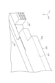
- FIG. 7 is a perspective view illustrating an example of a cover member.
- FIG. 8 is a schematic cross-sectional view of another example of an electricity storage module.
- FIG. 9 is a schematic cross-sectional view of a power storage module according to still another embodiment.
- FIG. 10 is a schematic cross-sectional view of a power storage module according to still another embodiment.
- FIG. 11 is a schematic diagram showing a side surface of a module main body constituting yet another electricity storage module.
- 12 is a perspective view showing a part of the side surface of the module main body of FIG. 11.
- FIG. 13 is a perspective view showing another example of a cover member.
- FIG. 14 is a perspective view showing a state in which the cover member of FIG. 13 is attached to the module body.
- FIG. 15 is a cross-sectional view taken along line XV-XV in FIG.
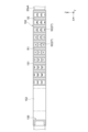
- FIG. 1 is a schematic perspective view showing a storage module according to this embodiment.
- the storage module 1 is a storage module used in batteries for various vehicles such as forklifts, hybrid cars, and electric cars.
- the storage module 1 is a secondary battery such as a nickel-metal hydride secondary battery or a lithium-ion secondary battery.
- the storage module 1 may be an electric double layer capacitor or an all-solid-state battery. Here, the case where the storage module 1 is a lithium-ion secondary battery is shown.
- the energy storage module 1 includes a module body 1A, a cover member 60, and an exterior film 90 (see FIG. 4).
- the module body 1A includes an electrode stack 10 and a sealing body 30 that surrounds the electrode stack 10.
- the module body 1A has a rectangular shape when viewed from the Z-axis direction (first direction) and has four outer sides 20s extending in the Z-axis direction.
- One outer side 20sA of the four outer sides 20s includes an area R1 that functions as a liquid inlet surface and an area R2 adjacent to this area R1.
- the cover member 60 in one example includes a first cover member 61 and a second cover member 71. In the illustrated example, two second cover members 71 are provided that are different in size and detailed shape but have the same basic configuration, such as the mounting method to the module body 1A.
- FIG. 2 is a schematic diagram showing a side of a module body constituting an energy storage module.
- FIG. 3 is a schematic cross-sectional view of an example of a module body. Note that FIG. 2 shows the outer side surface 20sA of the module body 1A, and FIG. 3 shows a cross-section along line III-III in FIG. 2.
- the electrode stack 10 includes multiple electrodes stacked along the Z-axis direction. The Z-axis direction is the stacking direction of the electrodes, which is the height direction of the energy storage module 1.
- the multiple electrodes include multiple bipolar electrodes 11, a positive terminal electrode 12, and a negative terminal electrode 13. Separators 14 are interposed between adjacent electrodes.
- the bipolar electrode 11 has a collector 15, a positive electrode active material layer 16, and a negative electrode active material layer 17.
- the collector 15 is rectangular when viewed from the Z-axis direction and has a sheet shape.
- the active material layers (positive electrode active material layer 16, negative electrode active material layer 17) are provided in the center of the collector 15 when viewed from the Z-axis direction, and are not provided on the peripheral portion 15c of the collector 15.
- the negative electrode active material layer 17 is provided on the other surface 15b of the collector 15.
- the multiple bipolar electrodes 11 are stacked so that the positive electrode active material layer 16 of one bipolar electrode 11 and the negative electrode active material layer 17 of the other bipolar electrode 11 adjacent to each other in the stacking direction face each other.
- one surface 15a of the collector 15 is the surface facing one side in the Z-axis direction (the side where the negative electrode terminal electrode 13 is arranged in FIG. 3).
- the other surface 15b of the current collector 15 faces the other side in the Z-axis direction (the side where the positive terminal electrode 12 is located in FIG. 3).
- the positive electrode active material layer 16 and the negative electrode active material layer 17 are rectangular when viewed from the Z-axis direction.
- the negative electrode active material layer 17 is slightly larger than the positive electrode active material layer 16 when viewed from the Z-axis direction. In a plan view viewed from the Z-axis direction, the entire formation area of the positive electrode active material layer 16 is located within the formation area of the negative electrode active material layer 17.
- the positive electrode terminal electrode 12 has a current collector 15 and a positive electrode active material layer 16 provided on one surface 15a of the current collector 15.
- the positive electrode terminal electrode 12 does not have a positive electrode active material layer 16 or a negative electrode active material layer 17 on the other surface 15b of the current collector 15. In other words, no active material layer is provided on the other surface 15b of the current collector 15 of the positive electrode terminal electrode 12.
- the positive electrode terminal electrode 12 is laminated on the bipolar electrode 11 at one end of the electrode laminate 10 in the Z-axis direction.
- the positive electrode terminal electrode 12 is laminated on the bipolar electrode 11 so that the positive electrode active material layer 16 faces the negative electrode active material layer 17 of the bipolar electrode 11.
- the negative terminal electrode 13 has a current collector 15 and a negative active material layer 17 provided on the other surface 15b of the current collector 15.
- the negative terminal electrode 13 does not have a positive active material layer 16 or a negative active material layer 17 on one surface 15a of the current collector 15. In other words, no active material layer is provided on one surface 15a of the current collector 15 of the negative terminal electrode 13.
- the negative terminal electrode 13 is laminated on the bipolar electrode 11 at the end of the other side opposite to the one side on which the positive terminal electrode 12 is provided in the Z-axis direction of the electrode laminate 10.
- the negative terminal electrode 13 is laminated on the bipolar electrode 11 so that the negative active material layer 17 faces the positive active material layer 16 of the bipolar electrode 11.
- the current collectors of the bipolar electrode 11, the positive terminal electrode 12, and the negative terminal electrode 13 are designated by the same reference numeral as the current collector 15, but the current collectors of the bipolar electrode 11, the positive terminal electrode 12, and the negative terminal electrode 13 may be the same as or different from each other.
- Separators 14 are disposed between adjacent bipolar electrodes 11, between the positive terminal electrode 12 and the bipolar electrode 11, and between the negative terminal electrode 13 and the bipolar electrode 11. Separators 14 are disposed between the positive electrode active material layer 16 and the negative electrode active material layer 17, and separate the positive electrode active material layer 16 and the negative electrode active material layer 17. Separators 14 allow charge carriers such as lithium ions to pass through while preventing short circuits caused by contact between adjacent electrodes.
- the current collector 15 is a chemically inactive electrical conductor for continuing to pass current through the positive electrode active material layer 16 and the negative electrode active material layer 17 during discharging or charging of the lithium ion secondary battery.
- the material of the current collector 15 is, for example, a metal material, a conductive resin material, or a conductive inorganic material.
- the conductive resin material include resins in which a conductive filler is added as necessary to a conductive polymer material or a non-conductive polymer material.
- the current collector 15 may have multiple layers. In this case, each layer of the current collector 15 may contain the above-mentioned metal material or conductive resin material.
- a coating layer may be formed on the surface of the current collector 15.
- the coating layer may be formed by a known method such as plating or spray coating.
- the current collector 15 may be, for example, in the form of a plate, foil (e.g., metal foil), film, or mesh. Examples of metal foil include aluminum foil, copper foil, nickel foil, titanium foil, and stainless steel foil.
- the current collector 15 may be an alloy foil or clad foil of the above metals.
- the thickness of the current collector 15 may be, for example, 1 ⁇ m to 100 ⁇ m.
- the current collector 15 is a foil in which aluminum foil and copper foil are integrated, or is an aluminum foil.
- the positive electrode active material layer 16 contains a positive electrode active material capable of absorbing and releasing charge carriers such as lithium ions.
- the positive electrode active material include lithium composite metal oxides having a layered rock salt structure, metal oxides having a spinel structure, polyanion compounds, and the like.
- the positive electrode active material may be any material that can be used in lithium ion secondary batteries.
- the positive electrode active material layer 16 may contain a plurality of positive electrode active materials.
- the positive electrode active material layer 16 contains olivine-type lithium iron phosphate (LiFePO 4 ) as a composite oxide.
- the negative electrode active material layer 17 contains a negative electrode active material capable of absorbing and releasing charge carriers such as lithium ions.
- the negative electrode active material may be any of a simple substance, an alloy, or a compound. Examples of the negative electrode active material include Li, carbon, and metal compounds.
- the negative electrode active material may be an element capable of being alloyed with lithium or a compound thereof. Examples of carbon include natural graphite, artificial graphite, hard carbon (hardly graphitizable carbon), and soft carbon (easily graphitizable carbon). Examples of artificial graphite include highly oriented graphite and mesocarbon microbeads. Examples of elements capable of being alloyed with lithium include silicon and tin.
- the negative electrode active material layer 17 contains graphite as a carbon-based material.
- Each of the positive electrode active material layer 16 and the negative electrode active material layer 17 may further contain, as necessary, a conductive assistant to increase electrical conductivity, a binder, an electrolyte (polymer matrix, ionically conductive polymer, electrolyte solution, etc.), an electrolyte supporting salt (lithium salt) to increase ionic conductivity, etc.
- the conductive assistant is added to increase the conductivity of each electrode (bipolar electrode 11, positive terminal electrode 12, negative terminal electrode 13).
- the conductive assistant is, for example, acetylene black, carbon black, graphite, etc.
- Binders include fluorine-containing resins such as polyvinylidene fluoride, polytetrafluoroethylene, and fluororubber, thermoplastic resins such as polypropylene and polyethylene, imide resins such as polyimide and polyamideimide, alkoxysilyl group-containing resins, acrylic resins such as acrylic acid or methacrylic acid, styrene-butadiene rubber (SBR), carboxymethyl cellulose, alginates such as sodium alginate and ammonium alginate, water-soluble cellulose ester crosslinked bodies, and starch-acrylic acid graft polymers. These binders can be used alone or in combination. Examples of the solvent that can be used include water and N-methyl-2-pyrrolidone (NMP).
- NMP N-methyl-2-pyrrolidone
- the separator 14 may be, for example, a porous sheet or nonwoven fabric containing a polymer that absorbs and retains an electrolyte.
- materials for the separator 14 include polypropylene, polyethylene, polyolefin, polyester, and the like.
- the separator 14 may have a single-layer structure or a multi-layer structure.
- the multi-layer structure may have, for example, a ceramic layer as an adhesive layer or a heat-resistant layer.
- the separator 14 may be impregnated with an electrolyte.
- the separator 14 may be composed of an electrolyte such as a polymer electrolyte or an inorganic electrolyte.
- Examples of the electrolyte impregnated in the separator 14 include a liquid electrolyte (electrolyte solution) containing a non-aqueous solvent and an electrolyte salt dissolved in the non-aqueous solvent, or a polymer gel electrolyte containing an electrolyte held in a polymer matrix.
- a liquid electrolyte electrolyte solution
- electrolyte salt dissolved in the non-aqueous solvent
- polymer gel electrolyte containing an electrolyte held in a polymer matrix.
- the electrolyte salt may be a known lithium salt such as LiClO4 , LiAsF6 , LiPF6 , LiBF4 , LiCF3SO3 , LiN( FSO2 ) 2 , or LiN( CF3SO2 ) 2 .
- the non-aqueous solvent may be a known solvent such as cyclic carbonates, cyclic esters, chain carbonates, chain esters, or ethers. Two or more of these known solvent materials may be used in combination.
- the sealing body 30 includes a sealing body 20 and a reinforcing member 50.
- the sealing body 20 is formed in a frame shape on the periphery of the electrode laminate 10 so as to surround the periphery of the electrode laminate 10 when viewed from the Z-axis direction.
- the sealing body 20 can be joined to each of the one surface 15a and the other surface 15b of the current collector 15 at the peripheral portion 15c of each current collector 15.
- the sealing body 20 can form an internal space S between the current collectors 15 adjacent in the Z-axis direction and can seal each of the internal spaces S.
- each internal space S contains an electrolyte (not shown).
- the sealing body 20 cooperates with the current collectors 15 adjacent in the Z-axis direction to define the internal space S in which the electrolyte is contained.
- the sealing body 20 can suppress the electrolyte contained in the internal space S from leaking out to the outside.
- the sealing body 20 can prevent air, moisture, etc. from entering the internal space S from the outside of the electrode stack 10.
- the sealing body 20 can prevent, for example, gas generated in each electrode due to a charge/discharge reaction, etc. from leaking to the outside of the energy storage module 1.
- the edge of the separator 14 is joined to the sealing body 20.
- the sealing body 20 contains an insulating material. Examples of materials for the sealing body 20 include various resin materials such as polypropylene, polyethylene, polystyrene, ABS resin, acid-modified polypropylene, acid-modified polyethylene, and acrylonitrile-styrene resin.
- the sealing body 20 of the example includes a plurality of sealing materials 21, a pair of end sealing materials 24, and a plurality of spacers 22.
- the sealing materials 21, the end sealing materials 24, and the spacers 22 may be frame-shaped members formed in a sheet shape.
- the sealing body 20 also has a welded end portion 23.
- the sealing material 21 is frame-shaped when viewed from the Z-axis direction, and is provided along the peripheral portion 15c of the current collector 15.
- the sealing material 21 is provided so as to extend from one surface 15a of the current collector 15 through the end face to the other surface 15b, and covers the peripheral portion 15c.
- the sealing material 21 has an inner portion that overlaps with the current collector 15 and an outer portion that is located outside the edge of the current collector 15 on one surface 15a and the other surface 15b of the current collector 15, respectively, when viewed from the Z direction, and the outer portions of the pair of sealing materials 21 adjacent to each other across the current collector 15 are connected to each other.
- the sealant 21 can be welded to at least one of the one surface 15a and the other surface 15b of the current collector 15. In this embodiment, the sealant 21 is welded to both the one surface 15a and the other surface 15b of the current collector 15.
- the end seal material 24 has a frame shape when viewed from the Z-axis direction, and is provided along the peripheral portion 15c of the current collector 15 that constitutes the positive terminal electrode 12 and the negative terminal electrode 13, respectively. Therefore, the end seal material 24 is arranged so as to sandwich the multiple seal materials 21 from the Z-axis direction.
- the end seal material 24 can be welded to at least one of the one surface 15a and the other surface 15b of the current collector 15.
- the end seal material 24 of this embodiment is welded to both the one surface 15a and the other surface 15b of the current collector 15.
- the spacer 22 has a frame shape when viewed from the Z-axis direction, and is arranged along the peripheral portion 15c of the current collector 15.
- the spacer 22 is arranged so as to be interposed between adjacent seal materials 21 in the Z-axis direction.
- the spacer 22 is also arranged so as to be interposed between adjacent seal materials 21 and end seal materials 24 in the Z-axis direction.
- the spacer 22 can maintain the distance between adjacent current collectors 15 in the Z-axis direction.
- seal materials 21, and end seal materials 24 define an internal space S between adjacent current collectors 15.
- the welded end 23 is formed by welding together and integrating the ends of the multiple seal materials 21, the pair of end seal materials 24, and the multiple spacers 22 that are opposite the internal space S.
- the welded end 23 has a frame shape that surrounds the electrode stack 10.
- the side of the welded end 23 opposite the internal space S extends along the Z-axis direction and constitutes the outer surface 20s of the sealing body 20.
- the sealing body 20 includes the outer surface 20s opposite the internal space S.
- the outer surface 20s may be formed as a flat surface.
- the sealing body 20 has a number of communication holes 27 that communicate with each of the multiple internal spaces S (see FIG. 3).
- the communication holes 27 are notched portions formed in the spacer 22, and are formed to penetrate the welded end portion 23.
- the communication holes 27 have one opening in the internal space S and the other opening on the outer surface 20s of the sealing body 20. In the illustrated example, an opening is formed on the outer surface 20sA.
- the reinforcing member 50 is formed so as to overlap the area of the outer surface 20sA where the communication holes 27 are formed.
- the reinforcing member 50 is molded into a predetermined shape to provide a plurality of liquid inlet ports that respectively communicate with the plurality of communication holes 27.
- the reinforcing member 50 is joined to the welded end portion 23.
- the reinforcing member 50 is integrally joined to the welded end portion 23 by injection molding.
- An example of the reinforcing member 50 includes a main body portion 51, a first overhang portion 55, and a second overhang portion 57.
- the main body 51 partially covers the outer surface 20sA.
- the main body 51 covers the outer surface 20sA so as to include the region R1 in which the multiple communication holes 27 are formed on the outer surface 20sA.
- the multiple communication holes 27 are each connected to the multiple internal spaces S.
- 30 communication holes 27 corresponding to the internal spaces of the 30 layers formed between each current collector 15 are arranged discretely in the X-axis direction and the Z-axis direction.
- the communication holes 27 corresponding to the internal spaces of the first to tenth layers are arranged at equal intervals along the X-axis direction with the positive terminal electrode 12 side as the base end, and the communication holes 27 corresponding to the internal spaces of the 11th to 20th layers and the communication holes 27 corresponding to the internal spaces of the 21st to 30th layers are arranged in order in the Z-axis direction below the internal spaces of the first to tenth layers.
- the main body 51 extends in a rectangular shape along the X-axis and Z-axis directions to cover the region R3 in which the 30 communication holes 27 are formed.
- the main body 51 is formed in a rectangular plate shape with a predetermined thickness in the Y-axis direction.
- the main body 51 has an opening 52 at a position corresponding to the communication hole 27.
- the main body 51 also has a protruding frame portion 53 (frame portion) that protrudes from the outer surface 20sA in the Y-axis direction (second direction) that intersects (is perpendicular to) the outer surface 20sA.
- the protruding frame portion 53 surrounds each of the openings 52 when viewed from the Y-axis direction, and functions as a partition wall that separates each of the openings 52.
- ten protruding frame portions 53 are arranged in the X-axis direction.
- the protruding frame portions 53 are used, as an example, when injecting electrolyte into each of the internal spaces S.
- the nozzle of an injection device is brought into close contact with the top surface of the protruding frame portions 53, and electrolyte is introduced from the nozzle into the spaces of each of the protruding frame portions 53. This makes it possible to inject electrolyte into the internal spaces S from the openings 52 and the communication holes 27.
- the first overhang portion 55 and the second overhang portion 57 are formed by connecting both ends of the main body portion 51 in the Z-axis direction.
- the first overhang portion 55 partially covers one edge of the welded end portion 23 in the Z-axis direction (the positive side in the Z-axis direction).
- the first overhang portion 55 partially covers the end seal material 24 joined to the positive terminal electrode 12.
- the edge 55a of the first overhang portion 55 extends from the edge of the welded end portion 23 to a position outside the inner edge 22a of the spacer 22 and the inner edge 21a of the seal material 21 when viewed from the Z-axis direction.
- the first overhang portion 55 may be formed in a rectangular plate shape having the same length as the main body portion 51 in the X-axis direction.
- the second overhang portion 57 partially covers the other edge of the welded end portion 23 in the Z-axis direction (negative side in the Z-axis direction).
- the second overhang portion 57 partially covers the end seal material 24 joined to the negative terminal electrode 13.
- the edge 57a of the second overhang portion 57 extends from the edge of the welded end portion 23 to a position outside the inner edge 22a of the spacer 22 and the inner edge 21a of the seal material 21 when viewed from the Z-axis direction.
- the second overhang portion 57 may be formed in a rectangular plate shape having the same length as the main body portion 51 in the X-axis direction.
- a conductive member functioning as a terminal for extracting current from the energy storage module 1 may be disposed and electrically connected to the one surface 15a of the current collector 15 of the positive terminal electrode 12 and the other surface 15b of the current collector 15 of the negative terminal electrode 13 that are exposed from the sealing body 20.
- the conductive member may be disposed between the multiple energy storage modules 1 and used to electrically connect the adjacent energy storage modules 1.
- the restraining load from the restraining members may be applied to the electrode stack 10 via the conductive member.
- a cooling flow path may be formed in the conductive member.
- the energy storage module 1 can be cooled by circulating a cooling medium through the cooling flow path formed in the conductive member.
- FIGS. 4 and 5 are schematic cross-sectional views showing an example of an energy storage module.
- FIG. 6 is a perspective view showing a connection portion between example cover members.
- FIG. 7 is a perspective view showing an example of a cover member.
- FIG. 4 is a cross-sectional view of the energy storage module 1 at a position where a first cover member 61 constituting the cover member 60 is provided
- FIG. 5 is a cross-sectional view of the energy storage module 1 at a position where a second cover member 71 constituting the cover member 60 is provided.
- the cover member 60 covers the outer surface 20sA of the sealing body 30 and is fixed to the sealing body 30.
- the first cover member 61 covers the area of the outer surface 20sA where the reinforcing member 50 is formed.
- the second cover member 71 covers the area of the outer surface 20sA where the reinforcing member 50 is not formed.
- the first cover member 61 includes an attachment member 62 fixed to the sealing body 30, and a cover body 65 fixed to the attachment member 62.
- the attachment member 62 may be a resin member formed into a substantially rectangular plate shape.
- the size of the attachment member 62 in the Z-axis direction may be the same as the size of the reinforcing member 50 in the Z-axis direction.
- the size of the attachment member 62 in the X-axis direction may be the same as the size of the reinforcing member 50 in the X-axis direction.
- the mounting member 62 may be welded to the top surface of the protruding frame portion 53. By welding the mounting member 62 to the protruding frame portion 53, each of the 30 openings 52 separated by the protruding frame portion 53 is sealed.
- the mounting member 62 has groove portions 63 formed along the X-axis direction on both end faces in the Z-axis direction. A region 62a of the mounting member 62 closer to the module main body 1A than the groove portions 63 may be the same size as the reinforcing member 50 in the Z-axis direction. A region 62b of the mounting member 62 farther from the module main body 1A than the groove portions 63 may be smaller than the reinforcing member 50 in the Z-axis direction.
- the cover body 65 of one example clamps the mounting member 62 from the Z-axis direction.
- the cover body 65 includes a first wall portion 66 and a second wall portion 67 that face each other in the Z-axis direction, and a third wall portion 68 that extends in the XZ plane to connect the first wall portion 66 and the second wall portion 67.
- the connection portion 68a between the first wall portion 66 and the third wall portion 68 and the connection portion 68b between the second wall portion 67 and the third wall portion 68 are formed in a chamfered shape such that the corners are chamfered.
- the chamfered shape may be a C-chamfered shape or an R-chamfered shape (the illustrated example has a C-chamfered shape).
- the corners (connection portions 68a, 68b) formed by the connection between the walls may be formed to be inclined at an angle or may be formed to be rounded.
- the cover body 65 may be formed so that the interior is hollow to reduce weight.
- the hollow interior may have one or more reinforcing ribs 69.
- the rib 69 is plate-shaped extending along the YZ plane and connects the first wall portion 66 and the second wall portion 67 to each other.
- the rib 69 in the illustrated example is also connected to the third wall portion 68.
- the cover body 65 may have multiple ribs 69 at equal intervals in the X-axis direction.
- the position in the Y-axis direction of the end of the rib 69 opposite the third wall portion 68 may be separated from the mounting member 62 at the position where the engaging claws 66a, 67a described below are provided in order to ensure the amount of deflection of the first wall portion 66 and the second wall portion 67. Additionally, the end of the rib 69 opposite the third wall portion 68 may abut against the mounting member 62 so that the position of the cover body 65 in the Y-axis direction is restricted in a position where the locking claws 66a and 67a are not provided.
- the first wall portion 66 and the second wall portion 67 may each have a locking claw 66a, 67a.
- the first wall portion 66 and the second wall portion 67 have locking claws 66a, 67a that protrude toward each other at the end opposite the third wall portion 68.
- six locking claws 66a, 67a are formed at equal intervals in the X direction (see FIG. 1).
- the locking claws 66a, 67a engage with the groove portion 63 of the mounting member 62, so that the cover body 65 can clamp the mounting member 62 and be fixed to the mounting member 62.
- the cover body 65 is fixed to the sealing body 30 via the mounting member 62, and the first cover member 61 is fixed to the sealing body 30.
- multiple slits 64 extending in the Y-axis direction are formed at the ends of the first wall portion 66 and the second wall portion 67 opposite the third wall portion 68 (see FIG. 1), which makes it easier for the locking claws 66a, 67a to bend in the Z-axis direction.
- the slits 64 may be formed to sandwich the locking claws 66a, 67a, for example.
- the example second cover member 71 unlike the first cover member 61, does not have an attachment member and is fixed directly to the module main body 1A.
- the example second cover member 71 includes a first wall portion 76 and a second wall portion 77 that face each other in the Z axis direction, and a third wall portion 78 that extends in the XZ plane to connect the first wall portion 76 and the second wall portion 77.
- a connection portion 78a between the first wall portion 76 and the third wall portion 78, and a connection portion 78b between the second wall portion 77 and the third wall portion 78 are each formed in a chamfered shape, similar to the cover main body 65 of the first cover member 61.
- the second cover member 71 may be formed so that the inside is hollow to reduce weight.
- the hollow interior may have one or more reinforcing ribs 79.
- the rib 79 is plate-shaped extending along the YZ plane and connects the first wall portion 76 and the second wall portion 77 to each other.
- the rib 79 in the illustrated example is also connected to the third wall portion 78.
- the second cover member 71 may have multiple ribs 79 at equal intervals in the X-axis direction (see FIG. 7).
- the position in the Y-axis direction of the end of the rib 79 opposite the third wall portion 78 may be separated from the sealing body portion 20 at the position where the protrusions 76a and 77a described below are provided in order to ensure the amount of deflection of the first wall portion 76 and the second wall portion 77. Furthermore, the end of the rib 79 opposite the third wall portion 78 may abut against the sealing body 20 so that the position of the second cover member 71 in the Y-axis direction is restricted in a position where the protrusions 76a and 77a are not provided.
- the first wall portion 76 and the second wall portion 77 may have protrusions 76a, 77a, respectively.
- the first wall portion 76 and the second wall portion 77 have protrusions 76a, 77a facing each other at the end opposite the third wall portion 78.
- three protrusions are formed at equal intervals in the X direction.
- the protrusions 76a, 77a sandwich the sealing main body portion 20, so that the second cover member 71 can be fixed to the sealing body 30.
- a plurality of slits 74 see FIG.
- the slits 74 may be formed to sandwich the protrusions 76a, 77a, for example.
- the protrusions 76a, 77a may be engaged with both end surfaces in the Z-axis direction of the welded end 23 (see FIG. 3).
- the welded end 23 may or may not have a recess or the like for the protrusions 76a, 77a to engage with. If the welded end 23 does not have a recess or the like, the protrusions 76a, 77a can bend and pinch the welded end 23, thereby fixing the second cover member 71 to the welded end 23.
- FIG. 6 shows a recess 83 provided in the cover body 65 of the first cover member 61 and a locking claw 81 provided in the second cover member 71.
- the first cover member 61 and the second cover member 71 are connected to each other by the locking claw 81 and a recess 83 corresponding to the locking claw 81.
- the example second cover member 71 has a locking claw 81 protruding in the X-axis direction from the first wall portion 76 and the second wall portion 77.
- a recess 83 recessed in the Z-axis direction to correspond to the locking claw 81 is formed in the first wall portion 66 and the second wall portion 67 of the cover body 65 of the first cover member 61.
- the first cover member 61 may have a recess 83 that corresponds to the locking claw 81 of one second cover member 71, and a locking claw 81 that corresponds to the recess 83 of the other second cover member 71 (see FIG. 1).
- the cover body 65 and the second cover member 71 are connected by engaging the locking claw 81 of the second cover member 71 with the recess 83 of the cover body 65.
- the first wall portion 66, the second wall portion 67, and the third wall portion 68 of the cover body 65 are flush with the first wall portion 76, the second wall portion 77, and the third wall portion 78 of the second cover member 71, respectively. Also, as shown in FIG.
- the first wall portion 66 of the cover body 65, the region 62a of the mounting member 62 close to the module body 1A, and the first overhang portion 55 of the reinforcing member 50 may be flush with each other, and the second wall portion 67 of the cover body 65, the region 62a of the mounting member 62, and the second overhang portion 57 of the reinforcing member 50 may be flush with each other.
- the positions of the ends 76e, 77e of the first wall portion 76 and the second wall portion 77 of the second cover member 71 opposite the third wall portion 78 may be the same as the positions of the edge 55a of the first overhang portion 55 and the edge 57a of the second overhang portion 57 (see FIG. 4).
- the exterior film 90 shown in Figures 4 and 5 may be, for example, a laminate film including a metal layer. That is, the exterior film 90 may be a sheet-like member in which at least a portion of a metal layer such as aluminum is covered with a resin layer.
- the exterior film 90 surrounds and accommodates the entire module body 1A and the cover member 60. As a result, the cover member 60 is interposed between the sealing body 30 of the module body 1A and the exterior film 90. In this configuration, the outer surface 20sA of the module body 1A on which the liquid injection port is provided is not in contact with the exterior film 90.
- the metal layers of the exterior film 90 that are interposed between the positive terminal electrode 12 and the conductive member, and between the negative terminal electrode 13 and the conductive member, respectively, may be exposed from the resin layer. This allows current to be extracted from the energy storage module 1 using the conductive member.
- the entire metal layer of the exterior film 90 may be covered with a resin layer, and then current may be extracted from the energy storage module 1 by terminals connected to the positive terminal electrode 12 and the negative terminal electrode 13.
- the example energy storage module 1 includes an electrode stack 10 in which multiple electrodes, each including a current collector 15, are stacked in the Z-axis direction, a sealing body 30 that is provided on the electrode stack 10 so as to surround the electrode stack 10 when viewed from the Z-axis direction and is configured to seal multiple internal spaces S formed between adjacent current collectors 15 in the Z-axis direction, an exterior film 90 that surrounds and houses the electrode stack 10 and the sealing body 30, and a cover member 60 that is housed in the exterior film 90 so as to be interposed between the sealing body 30 and the exterior film 90, covers the outer surface 20s of the sealing body 30 extending in the Z-axis direction, and is fixed to the sealing body 30.
- a cover member 60 is interposed between the sealing body 30 and the exterior film 90, and the cover member 60 is fixed not to the electrode stack 10 but to the sealing body 30 that surrounds the electrode stack 10. In this way, since the cover member 60 is not directly fixed to the electrode stack 10, deformation and damage to the electrode stack 10 caused by the cover member 60 is suppressed. Also, in the above example, the cover member 60 that may come into contact with the exterior film 90 has connection portions 68a, 68b formed in a chamfered shape, so damage to the exterior film 90 is suppressed.
- the sealing body 30 in one example may have a plurality of communication holes 27 formed to communicate with each of the plurality of internal spaces S and to have an opening 52 on the side surface, and a protruding frame portion 53 protruding in the Y-axis direction from the outer side surface 20sA so as to surround each opening 52 of the plurality of communication holes 27, and the cover member 60 may cover the protruding frame portion 53.
- the protruding frame portion 53 is prevented from coming into contact with the exterior film 90, so that deformation and damage of the exterior film 90 due to the protruding frame portion 53 is prevented.
- wrinkles are less likely to form in the exterior film 90, so that damage to the exterior film 90 when the energy storage module 1 expands and contracts is prevented.
- the cover member 60 may be fixed to the protruding frame portion 53.
- the protruding frame portion 53 is prevented from coming into contact with the exterior film 90.
- the concept of fixing may include welding, clamping adhesion, and the like.
- the cover member 60 is welded to the protruding frame portion 53.
- the cover member 60 is fixed by clamping the protruding frame portion 53 from the Z-axis direction, it is conceivable that the protruding frame portion 53 will deform over time.
- the cover member 60 is welded to the protruding frame portion 53, deformation of the protruding frame portion 53 is prevented.
- An example of the cover member 60 may include an attachment member 62 welded to the protruding frame portion 53, and a cover body 65 that clamps the attachment member 62 from the Z-axis direction.
- the attachment member 62 as a dedicated part that is welded to the protruding frame portion 53, it is possible to reliably seal the protruding frame portion 53.
- the cover member 60 may be composed of a first cover member 61 that covers a region R1 of the outer surface 20sA where the protruding frame portion 53 is formed, and a second cover member 71 that covers a region R2 of the outer surface 20sA where the protruding frame portion 53 is not formed, and the first cover member 61 and the second cover member 71 may be connected to each other.
- the outer surface 20sA can be easily covered. Also, by dividing the cover member into multiple parts, the occurrence of warping or the like in each cover member is suppressed.
- the positions of the ends 76e, 77e of the first wall portion 76 and the second wall portion 77 of the second cover member 71 are the same as the positions of the edge 55a of the first overhang portion 55 and the edge 57a of the second overhang portion 57, so that the formation of a step between the second cover member 71 and the overhang portion is suppressed.
- wrinkles are less likely to form in the exterior film 90, so that damage to the exterior film 90 when the energy storage module 1 expands and contracts is suppressed.
- FIG. 8 is a schematic cross-sectional view of another example of a storage module.
- FIG. 8 is a cross-sectional view of the storage module at a position where a first cover member 161 is provided as a modified example of the first cover member 61.
- the exterior film 90 is omitted.
- the first cover member 161 may have a substantially rectangular plate shape.
- the size of the first cover member 161 in the Z-axis direction may be the same as the size of the reinforcing member 50 in the Z-axis direction.
- the size of the first cover member 161 in the X-axis direction may be the same as the size of the reinforcing member 50 in the X-axis direction.
- the first cover member 161 does not have an attachment member, and is welded to the reinforcing member 50.
- the first cover member 161 is welded to the protruding frame portion 53 of the reinforcing member 50.
- the first cover member 161 may be formed to be hollow on the inside like the cover body 65, or may not have a space on the inside.
- FIG. 9 is a schematic cross-sectional view of a further example of a storage module.
- FIG. 9 is a cross-sectional view of the storage module at a position where a second cover member 171 is provided as a modified example of the second cover member 71.
- the exterior film 90 is omitted.
- the second cover member 171 may have a pair of protruding pieces 172 protruding in the Y-axis direction from both ends in the Z-axis direction. With the sealing body 20 inserted between the protruding pieces 172, the outer surface 20s and the side surface 171b of the second cover member 171 facing the outer surface 20s are welded. In this state, the position of the end 172a of the protruding piece 172 may be the same as the position of the edge 55a of the first overhang portion 55 and the edge 57a of the second overhang portion 57 (see FIG. 4).
- FIG. 10 is a schematic cross-sectional view of a further example of a storage module.
- FIG. 10 is a cross-sectional view of the storage module at a position where a second cover member 271 is provided as a modified example of the second cover member 71.
- the exterior film 90 is omitted.
- the second cover member 271 has a first wall portion 276 and a second wall portion 277 facing each other in the Z-axis direction, a third wall portion 278 extending in the XZ plane to connect the first wall portion 276 and the second wall portion 277, and a reinforcing rib 279.
- the first wall portion 276 and the second wall portion 277 may have locking claws 276a, 277a, respectively.
- first wall portion 276 and the second wall portion 277 have locking claws 276a, 277a protruding to face each other at the end opposite the third wall portion 278.
- grooves 223 are formed along the X-axis direction on both end faces of the sealing body 20 in the Z-axis direction, and the second cover member 271 may be fixed to the sealing body 20 by engaging the locking claws 276a and 277a with the grooves 223 and clamping the sealing body 20.
- the exterior film 90 is not limited to a laminate film made of a metal layer and a resin layer.
- the exterior film 90 may be a laminate film made of a resin film that does not include a metal layer.
- Such a resin film may be composed of a resin layer with low moisture permeability.
- the interior of the exterior film 90 may be sealed in a reduced pressure state.
- the exterior film 90 is pressed by atmospheric pressure and adheres closely to the module body 1A.
- protruding parts of the sealing body 30, such as the protruding frame portion 53 may damage the exterior film 90, but the provision of the cover member 60 can prevent such damage.
- the three outer sides 20s other than the outer side 20sA on which the protruding frame portion 53 is not provided may be covered by a cover member similar to the second cover member 71.
- a cover member may be provided only on the outer side 20s arranged opposite the outer side 20sA, a cover member may be provided on one or both of the two outer sides 20s perpendicular to the outer side 20sA, or a cover member may be provided on all three outer sides 20s.
- the cover member may cover the entire surface or a part of the outer side 20s.
- the outer surface 20sA may be covered only by the second cover members.
- the extensions may be configured to have an outer shape similar to that of the first cover member 61 and cover the protruding frame portion 53.
- the opening of the protruding frame portion 53 may be sealed with a sealing film or the like.
- Fig. 11 is a schematic diagram showing a side view of a module body constituting a further energy storage module.
- Fig. 12 is a perspective view showing a portion of the side view of the module body of Fig. 11.
- Fig. 13 is a perspective view showing a cover member of another example.
- Fig. 14 is a perspective view showing the cover member of Fig. 13 attached to the module body.
- Fig. 15 is a cross-sectional view taken along line XV-XV of Fig. 14.
- the reinforcing member 150 has a main body portion 151 that partially covers the outer surface 20sA.
- the main body portion 151 has a protruding frame portion 53 similar to the main body portion 51 described above.
- the reinforcing member 150 also includes a terminal portion 152 for voltage detection.
- the terminal portion 152 is formed in the main body portion 151 at a position shifted toward the positive side in the X-axis direction from the multiple protruding frame portions 53.
- the terminal portion 152 can provide multiple terminals that are electrically connected to the multiple current collectors 15, respectively.
- a connector unit 152a (see FIG. 12) that is electrically connected to the multiple terminals can be fixed to the terminal portion 152.
- an engagement portion 155 that engages with the cover member 370 is formed at a position shifted toward the positive side in the X-axis direction from the terminal portion 152.
- the engagement portion 155 is formed at the end of the main body 151 in the X-axis direction.
- the engagement portion 155 may be fitted into the cover member 370.
- An example of the engagement portion 155 protrudes from the main body 151 in the Y direction.
- the engagement portion 155 has a central portion 155a extending along the Z-axis direction, and a pair of side portions 155b, 155c connected to both ends of the central portion 155a in the Z-axis direction.
- the side portions 155b, 155c extend toward the positive side in the X-axis direction from the central portion 155a as a base end.
- the distance L1 along the Z-axis direction from the top surface of the upper side portion 155b to the bottom surface of the lower side portion 155c is shorter than the length L2 of the main body portion 151 in the Z-axis direction.
- the cover member 370 includes a first wall portion 371 and a second wall portion 372 that face each other in the Z-axis direction, and a third wall portion 373 that extends in the XZ plane to connect the first wall portion 371 and the second wall portion 372.
- the cover member 370 also includes a fourth wall portion 374 and a fifth wall portion 375 that face each other in the X-axis direction and extend in the YZ plane to connect the first wall portion 371, the second wall portion 372, and the third wall portion 373.
- the connection portion between the third wall portion 373 and the fifth wall portion 375 is curved in an arc shape from the Z-axis direction.
- the corners 370k that connect the first wall portion 371 and the second wall portion 372 to the third wall portion 373 and the fourth wall portion 374 are formed in an indented shape.
- One or more reinforcing ribs 377 are provided inside the hollow cover member 370.
- the ribs 377 are plate-shaped extending along the YZ plane and connect the first wall portion 371, the second wall portion 372, and the third wall portion 373 to each other.
- the multiple ribs 377 may be arranged at equal intervals in the X-axis direction. As an example, the interval between adjacent ribs 377 is greater than the interval between the first wall portion 371 and the second wall portion 372.
- the first wall portion 371, the second wall portion 372, the fourth wall portion 374, the fifth wall portion 375, and the end faces of the ribs 377 facing away from the third wall portion 373 form a wall surface 379 facing the third wall portion 373.
- the first wall 371 and the second wall 372 are formed with a notch 378 near the fourth wall 374 to avoid interference with the end of the reinforcing member 150.
- the notch 378 is formed by recessing the wall surface 379 in the Y-axis direction toward the third wall 373.
- resin may protrude from the main body 151 of the reinforcing member 150 along the outer surface 20sA. In that case, the protruding resin portion may be accommodated in the space formed by the notch 378.
- the distance L3, which is the inside dimension between the first wall portion 371 and the second wall portion 372, may be the same as the distance L1, which is the outside dimension between the pair of side portions 155b, 155c of the engagement portion 155.
- distance L3 and distance L1 do not need to be exactly the same, as long as they are substantially the same.
- distance L3 in the cover member 370 in an unengaged state may be the same as distance L1 or slightly smaller.
- the outside dimension L4 between the first wall portion 371 and the second wall portion 372 may be the same as the length L2 of the main body portion 151 in the Z-axis direction.
- the cover member 370 is engaged with the engagement portion 155 formed on the main body portion 151 of the reinforcing member 150.
- the cover member 370 is engaged with the engagement portion 155 by fitting a pair of side portions 155b, 155c of the engagement portion 155 between the first wall portion 371 and the second wall portion 372.
- the first wall portion 371 and the second wall portion 372 may be flush with the first overhang portion 55 and the second overhang portion 57, respectively.
- the outer surface 20sA has the engaging portion 155 that engages with the cover member 370, so that the cover member 370 can be stably attached to the module main body 1A. Furthermore, since the engaging portion 155 is formed on the reinforcing member 150, excessive load is prevented from being applied to the welded end portion 23. Although an example in which the engaging portion 155 protrudes in the Y-axis direction has been shown, for example, a recess that is recessed in the Y-axis direction may be formed on the reinforcing member 150, and a protrusion that fits into the recess may be formed on the cover member. Furthermore, the cover member 370 and the engaging portion 155 may further have claws that engage with each other.
- the engaging portion 155 may be fitted between the walls that face each other in the X-axis direction.
- the cover member 370 may have a pair of ribs 377 to sandwich the engaging portion 155 from the X-axis direction.
- the engagement portion 155 may have a pair of side portions that extend along the YZ plane so as to abut against a pair of ribs 377.
- 1...energy storage module 10...electrode laminate, 11...bipolar electrode (electrode), 12...positive terminal electrode (electrode), 13...negative terminal electrode (electrode), 15...current collector, 20s...outer surface (side surface), 27...communicating hole, 50...reinforcing member, 53...protruding frame portion (frame portion), 60...cover member, 61...first cover member, 71...second cover member, 90...exterior film, S...internal space.
Landscapes
- Engineering & Computer Science (AREA)
- Chemical & Material Sciences (AREA)
- Chemical Kinetics & Catalysis (AREA)
- Electrochemistry (AREA)
- General Chemical & Material Sciences (AREA)
- Manufacturing & Machinery (AREA)
- Power Engineering (AREA)
- Microelectronics & Electronic Packaging (AREA)
- Sealing Battery Cases Or Jackets (AREA)
Abstract
蓄電モジュールは、それぞれが集電体を含む複数の電極が第1方向に積層された電極積層体と、第1方向から見て電極積層体を取り囲むように電極積層体に設けられ、第1方向に隣り合う集電体の間のそれぞれに形成される複数の内部空間を封止するように構成された封止体と、電極積層体及び封止体を取り囲んで収容する外装フィルムと、封止体と外装フィルムとの間に介在するように外装フィルムに収容され、封止体の第1方向に延在する側面を被覆し、封止体に固定されたカバー部材と、を備える。
Description
本開示は、蓄電モジュールに関する。
特許文献1には、電池が開示されている。この電池は、複数の電極が積層された発電要素と、発電要素を収納するための外装フィルムとを有する。発電要素の端部には、外部応力を受けた際の外装フィルムの変形により、発電要素が変形して発電要素が短絡することを抑制するためのカバーが設けられている。カバーは、発電要素の端部に嵌合されて固定されている。
しかしながら、上記のように電極が積層された電極積層体を含む蓄電モジュールでは、電極積層体にカバーを固定する際に、電極積層体の一部が変形または損傷する虞がある。
本開示は、電極積層体の変形及び損傷を抑制できる蓄電モジュールを提供する。
本開示の一側面に係る蓄電モジュールは、それぞれが集電体を含む複数の電極が第1方向に積層された電極積層体と、第1方向から見て電極積層体を取り囲むように電極積層体に設けられ、第1方向に隣り合う集電体の間のそれぞれに形成される複数の内部空間を封止するように構成された封止体と、電極積層体及び封止体を取り囲んで収容する外装フィルムと、封止体と外装フィルムとの間に介在するように外装フィルムに収容され、封止体の第1方向に延在する側面を被覆し、封止体に固定されたカバー部材と、を備える。
上記蓄電モジュールでは、封止体と外装フィルムとの間にカバー部材が介在している。当該カバー部材は、電極積層体ではなく電極積層体を囲む封止体に固定されている。そのため、カバー部材による電極積層体の変形及び損傷が抑制されている。
一例の封止体は、複数の内部空間のそれぞれに連通するとともに側面に開口を有するように形成された複数の連通孔と、複数の連通孔のそれぞれの開口を囲むように側面から側面に交差する第2方向に突出する枠部と、を有してもよく、カバー部材は、枠部を被覆していてもよい。この構成では、枠部が外装フィルムに接触することが抑制されるため、外装フィルムが枠部によって変形及び損傷することが抑制される。
一例のカバー部材は、枠部に固定されていてもよい。枠部にカバー部材が固定されることにより、枠部が外装フィルムに接触することが抑制される。
一例のカバー部材は、枠部に溶着される取付部材と、取付部材を挟持することで取付部材に固定されるカバー本体と、を含んでもよい。この構成では、枠部に溶着される専用の部品を有していることで、枠部の封止を確実に行うことができる。
カバー部材は、側面のうちで枠部が形成されている領域を被覆する第1カバー部材と、側面のうちで枠部が形成されていない領域を被覆する第2カバー部材と、によって構成されていてよく、第1カバー部材と第2カバー部材とは、互いに連結されていてよい。カバー部材が複数に分割されることにより、それぞれのカバー部材に反り等が発生することが抑制される。
本開示によれば、電極積層体の変形及び損傷を抑制できる蓄電モジュールを提供できる。
以下、図面を参照して一実施形態について説明する。なお、図面の説明において、同一又は同等の要素には同一の符号を付し、重複する説明を省略する場合がある。また、説明に際して、図面に示されたX軸、Y軸及びZ軸によって規定される直交座標系が参照され得る。
図1は、本実施形態に係る蓄電モジュールを示す模式的な斜視図である。図1に示す蓄電モジュール1では、外装フィルム90が省略されており、カバー部材60が分解されている。蓄電モジュール1は、例えば、フォークリフト、ハイブリッド自動車、電気自動車等の各種車両のバッテリに用いられる蓄電モジュールである。蓄電モジュール1は、例えばニッケル水素二次電池又はリチウムイオン二次電池等の二次電池である。蓄電モジュール1は、電気二重層キャパシタであってもよいし、全固体電池であってもよい。ここでは、蓄電モジュール1がリチウムイオン二次電池である場合を示す。
蓄電モジュール1は、モジュール本体1Aと、カバー部材60と、外装フィルム90(図4参照)とを備えている。モジュール本体1Aは、電極積層体10と、電極積層体10を取り囲む封止体30と、を備えている。モジュール本体1Aは、Z軸方向(第1方向)から見て矩形状を呈しており、Z軸方向に延在する4つの外側面20sを有している。4つの外側面20sのうちの一つの外側面20sAは、注液口面として機能する領域R1と、この領域R1に隣り合う領域R2とを含む。一例のカバー部材60は、第1カバー部材61と第2カバー部材71とを含んでいる。図示例では、サイズや細部形状は異なるが、モジュール本体1Aへの取り付け方式などの基本的な構成を同じくする2つの第2カバー部材71が設けられている。
図2は、蓄電モジュールを構成するモジュール本体の側面を示す模式図である。図3は、一例のモジュール本体の概略断面図である。なお、図2では、モジュール本体1Aの外側面20sAが示されており、図3は図2のIII-III線に沿った断面を示す。図3に示すように、電極積層体10は、Z軸方向に沿って積層された複数の電極を含む。Z軸方向は、電極の積層方向であって、蓄電モジュール1の高さ方向である。複数の電極は、複数のバイポーラ電極11と、正極終端電極12と、負極終端電極13と、を含む。互いに隣り合う電極の間には、セパレータ14が介在されている。
バイポーラ電極11は、集電体15と、正極活物質層16と、負極活物質層17と、を有している。集電体15は、Z軸方向から見て矩形状をなしており、シート状をなしている。活物質層(正極活物質層16、負極活物質層17)は、Z軸方向から見て集電体15の中央に設けられており、集電体15の周縁部15cには設けられていない。負極活物質層17は、集電体15の他方面15bに設けられている。複数のバイポーラ電極11は、積層方向に隣り合う一方のバイポーラ電極11の正極活物質層16と他方のバイポーラ電極11の負極活物質層17とが対面するように積層されている。ここでは、集電体15の一方面15aは、Z軸方向の一方(図3において負極終端電極13が配置される側)を向く面である。集電体15の他方面15bは、Z軸方向の他方(図3において正極終端電極12が配置される側)を向く面である。
正極活物質層16及び負極活物質層17は、Z軸方向から見て矩形状である。負極活物質層17は、Z軸方向から見て正極活物質層16よりも一回り大きい。Z軸方向から見た平面視において、正極活物質層16の形成領域の全体は、負極活物質層17の形成領域内に位置している。
正極終端電極12は、集電体15と、集電体15の一方面15aに設けられた正極活物質層16と、を有している。正極終端電極12は、集電体15の他方面15bにおいて正極活物質層16及び負極活物質層17を有していない。つまり、正極終端電極12の集電体15の他方面15bには、活物質層が設けられていない。正極終端電極12は、電極積層体10のZ軸方向の一方側の端部においてバイポーラ電極11に積層されている。正極終端電極12は、その正極活物質層16がバイポーラ電極11の負極活物質層17に対向するようにバイポーラ電極11に積層されている。
負極終端電極13は、集電体15と、集電体15の他方面15bに設けられた負極活物質層17と、を有している。負極終端電極13は、集電体15の一方面15aにおいて正極活物質層16及び負極活物質層17を有していない。つまり、負極終端電極13の集電体15の一方面15aには、活物質層が設けられていない。負極終端電極13は、電極積層体10のZ軸方向の、正極終端電極12が設けられた一方側とは反対の他方側の端部においてバイポーラ電極11に積層されている。負極終端電極13は、その負極活物質層17がバイポーラ電極11の正極活物質層16に対向するようにバイポーラ電極11に積層されている。なお、本実施形態では、バイポーラ電極11、正極終端電極12及び負極終端電極13のそれぞれの集電体を集電体15として同一の符号を付しているが、バイポーラ電極11、正極終端電極12及び負極終端電極13のそれぞれの集電体は、互いに同一であってもよいし、互いに異なっていてもよい。
セパレータ14は、隣り合うバイポーラ電極11同士の間、正極終端電極12とバイポーラ電極11との間、及び、負極終端電極13とバイポーラ電極11との間に配置されている。セパレータ14は、正極活物質層16と負極活物質層17との間に介在しており、正極活物質層16と負極活物質層17とを隔離する。セパレータ14は、隣り合う電極の接触による短絡を防止しつつ、リチウムイオン等の電荷担体を通過させる。
集電体15は、リチウムイオン二次電池の放電又は充電の間、正極活物質層16及び負極活物質層17に電流を流し続けるための化学的に不活性な電気伝導体である。集電体15の材料は、例えば、金属材料、導電性樹脂材料又は導電性無機材料等である。導電性樹脂材料としては、例えば、導電性高分子材料又は非導電性高分子材料に必要に応じて導電性フィラーが添加された樹脂等が挙げられる。集電体15は、複数の層を備えていてもよい。この場合、集電体15の各層は、上記の金属材料又は導電性樹脂材料を含んでいてもよい。
集電体15の表面には、被覆層が形成されていてもよい。当該被覆層は、例えばメッキ処理又はスプレーコート等の公知の方法によって形成されていてもよい。集電体15は、例えば、板状、箔状(例えば金属箔)、フィルム状又はメッシュ状等を呈していてもよい。金属箔としては、例えば、アルミニウム箔、銅箔、ニッケル箔、チタン箔又はステンレス鋼箔等が挙げられる。集電体15は、上記の金属の合金箔又はクラッド箔であってもよい。集電体15が箔状を呈している場合、集電体15の厚さは、例えば、1μm~100μmであってもよい。本実施形態では、集電体15は、アルミニウム箔と銅箔とを一体化させた箔、もしくはアルミニウム箔である。
正極活物質層16は、リチウムイオン等の電荷担体を吸蔵及び放出し得る正極活物質を含んでいる。正極活物質としては、例えば、層状岩塩構造を有するリチウム複合金属酸化物、スピネル構造を有する金属酸化物、ポリアニオン系化合物等が挙げられる。正極活物質は、リチウムイオン二次電池に使用可能なものであればよい。正極活物質層16は、複数の正極活物質を含んでいてもよい。本実施形態では、正極活物質層16は、複合酸化物としてのオリビン型リン酸鉄リチウム(LiFePO4)を含んでいる。
負極活物質層17は、リチウムイオン等の電荷担体を吸蔵及び放出し得る負極活物質を含んでいる。負極活物質は、単体、合金又は化合物のいずれであってもよい。負極活物質としては、例えば、Li、炭素、金属化合物等が挙げられる。負極活物質は、リチウムと合金化可能な元素もしくはその化合物等であってもよい。炭素としては、例えば、天然黒鉛、人造黒鉛、ハードカーボン(難黒鉛化性炭素)又はソフトカーボン(易黒鉛化性炭素)等が挙げられる。人造黒鉛としては、例えば、高配向性グラファイト、メソカーボンマイクロビーズ等が挙げられる。リチウムと合金化可能な元素としては、シリコン(ケイ素)又はスズ等が挙げられる。本実施形態では、負極活物質層17は、炭素系材料としての黒鉛を含んでいる。
正極活物質層16及び負極活物質層17のそれぞれ(以下、単に「活物質層」という場合がある)は、必要に応じて電気伝導性を高めるための導電助剤、結着剤、電解質(ポリマーマトリクス、イオン伝導性ポリマー、電解液等)、イオン伝導性を高めるための電解質支持塩(リチウム塩)等をさらに含み得る。導電助剤は、各電極(バイポーラ電極11、正極終端電極12、負極終端電極13)の導電性を高めるために添加される。導電助剤は、例えばアセチレンブラック、カーボンブラック又はグラファイト等である。
結着剤としては、ポリフッ化ビニリデン、ポリテトラフルオロエチレン、フッ素ゴム等の含フッ素樹脂、ポリプロピレン、ポリエチレン等の熱可塑性樹脂、ポリイミド、ポリアミドイミド等のイミド系樹脂、アルコキシシリル基含有樹脂、アクリル酸又はメタクリル酸等のアクリル系樹脂、スチレン-ブタジエンゴム(SBR)、カルボキシメチルセルロース、アルギン酸ナトリウム、アルギン酸アンモニウム等のアルギン酸塩、水溶性セルロースエステル架橋体、デンプン-アクリル酸グラフト重合体等が挙げられる。これらの結着剤は、単独で又は複数で用いられ得る。溶媒には、例えば、水、N-メチル-2-ピロリドン(NMP)等が用いられる。
セパレータ14は、例えば、電解質を吸収保持するポリマーを含む多孔性シート又は不織布であってもよい。セパレータ14の材料としては、例えば、ポリプロピレン、ポリエチレン、ポリオレフィン、ポリエステル等が挙げられる。セパレータ14は、単層構造又は多層構造を有していてもよい。多層構造は、例えば、接着層又は耐熱層としてのセラミック層等を有していてもよい。セパレータ14には、電解質が含浸されていてもよい。セパレータ14は、高分子電解質又は無機型電解質等の電解質によって構成されていてもよい。セパレータ14に含浸される電解質としては、例えば、非水溶媒と非水溶媒に溶解された電解質塩とを含む液体電解質(電解液)、又はポリマーマトリクス中に保持された電解質を含む高分子ゲル電解質等が挙げられる。
セパレータ14に電解液が含浸される場合、その電解質塩としては、LiClO4、LiAsF6、LiPF6、LiBF4、LiCF3SO3、LiN(FSO2)2、LiN(CF3SO2)2等の公知のリチウム塩が用いられていてもよい。また、非水溶媒としては、環状カーボネート類、環状エステル類、鎖状カーボネート類、鎖状エステル類、エーテル類等の公知の溶媒が用いられていてもよい。なお、二種以上のこれらの公知の溶媒材料が組合せて用いられていてもよい。
封止体30は、封止本体部20と補強部材50とを含む。封止本体部20は、Z軸方向から見て電極積層体10の周縁を包囲するように、電極積層体10の周縁に枠状に形成されている。封止本体部20は、それぞれの集電体15の周縁部15cにおいて、集電体15の一方面15a及び他方面15bのそれぞれに接合され得る。封止本体部20は、Z軸方向に隣り合う集電体15の間に内部空間Sを形成すると共に、当該内部空間Sのそれぞれを封止し得る。本実施形態におけるそれぞれの内部空間Sには、電解液(不図示)が収容されている。すなわち、封止本体部20は、Z軸方向に隣り合う集電体15と協働して、電解液が収容される内部空間Sを画成する。封止本体部20は、内部空間Sに収容された電解液が外部へ流出することを抑制し得る。
封止本体部20は、電極積層体10の外部から内部空間Sへの空気、水分等が侵入することを抑制し得る。封止本体部20は、例えば、充放電反応等により各電極で発生したガスが蓄電モジュール1の外部に漏れることを抑制し得る。セパレータ14の縁部は、封止本体部20に接合されている。封止本体部20は、絶縁材料を含んでいる。封止本体部20の材料としては、例えば、ポリプロピレン、ポリエチレン、ポリスチレン、ABS樹脂、酸変性ポリプロピレン、酸変性ポリエチレン、アクリロニトリルスチレン樹脂等の種々の樹脂材料が挙げられる。
一例の封止本体部20は、複数のシール材21、一対の端部シール材24、及び、複数のスペーサ22を含む。シール材21、端部シール材24及びスペーサ22は、シート状に形成された枠状部材であってもよい。また、封止本体部20には、溶着端部23が形成されている。シール材21は、Z軸方向からみて枠状であり、集電体15の周縁部15cに沿って設けられている。シール材21は、集電体15の一方面15aから端面を経て他方面15bに至るように設けられ、周縁部15cを被覆している。すなわち、シール材21は、集電体15の一方面15aおよび他方面15bにおいて、それぞれ、Z方向から見て、集電体15に重なる内側部と、集電体15の端縁よりも外側に位置する外側部とを備えており、集電体15を挟んで隣り合う一対のシール材21は外側部同士が接続されている。シール材21は、集電体15の一方面15a及び他方面15bのうちの少なくとも一方に溶着され得る。本実施化体のシール材21は、集電体15の一方面15a及び他方面15bの両方に溶着されている。
端部シール材24は、Z軸方向からみて、枠状を呈しており、正極終端電極12及び負極終端電極13をそれぞれ構成する集電体15の周縁部15cに沿って設けられている。したがって、端部シール材24は、複数のシール材21をZ軸方向から挟むように配置されている。端部シール材24は、集電体15の一方面15a及び他方面15bのうちの少なくとも一方に溶着され得る。本実施化体の端部シール材24は、集電体15の一方面15a及び他方面15bの両方に溶着されている。
スペーサ22は、Z軸方向からみて、枠状を呈しており、集電体15の周縁部15cに沿って配置されている。スペーサ22は、Z軸方向に隣り合うシール材21の間に介在するように配置されている。また、スペーサ22は、Z軸方向に隣り合うシール材21と端部シール材24との間に介在するように配置されている。スペーサ22は、Z軸方向に隣り合う集電体15同士の間の間隔を保持し得る。すなわち、スペーサ22、シール材21及び端部シール材24は、隣り合う集電体15同士の間に内部空間Sを画成する。
溶着端部23は、複数のシール材21、一対の端部シール材24及び複数のスペーサ22のうちの内部空間Sとは反対側の端部が互いに溶着されて一体化されることにより形成されている。溶着端部23は、Z軸方向から見て、電極積層体10を取り囲むように枠状を呈している。溶着端部23における内部空間Sとは反対側の側面は、Z軸方向に沿って延びており、封止本体部20の外側面20sを構成している。換言すれば、封止本体部20は、内部空間Sと反対側の外側面20sを含む。外側面20sは、平坦面として形成されていてよい。
封止本体部20は、複数の内部空間Sのそれぞれに連通する複数の連通孔27を有する(図3参照)。一例として、連通孔27は、スペーサ22に形成された切欠状部分であり、溶着端部23を貫通して形成されている。連通孔27は、内部空間Sに一方の開口を有するするとともに、封止本体部20の外側面20sに他方の開口を有している。図示例では、外側面20sAに開口が形成されている。
補強部材50は、外側面20sAのうちの連通孔27が形成された領域に重なるように形成されている。補強部材50は、所定の形状に成形されることにより、複数の連通孔27にそれぞれ連通する複数の注液口を提供する。補強部材50は、溶着端部23に接合されている。例えば、補強部材50は、射出成形によって、溶着端部23に対して一体的に接合されている。一例の補強部材50は、本体部51と、第1オーバーハング部55と、第2オーバーハング部57と、を含む。
本体部51は、外側面20sAを部分的に被覆する。例えば、本体部51は、外側面20sAに形成された複数の連通孔27が形成されている領域R1を含むように、外側面20sAを被覆している。上述のとおり、複数の連通孔27は、複数の内部空間Sにそれぞれ連通している。図2に示す例では、それぞれの集電体15間に形成された30層の内部空間に対応する30個の連通孔27が、X軸方向及びZ軸方向に離散して配置されている。より具体的には、正極終端電極12側を基端として1層目から10層目までの内部空間に対応した連通孔27が、X軸方向に沿って均等に離間して配置され、11層目から20層目までの内部空間に対応した連通孔27、及び、21層目から30層目までの内部空間に対応した連通孔27は、1層目から10層目までの内部空間の下方にZ軸方向にそれぞれ順番に配置されている。本体部51は、これら30個の連通孔27が形成された領域R3を被覆するために、X軸方向及びZ軸方向に沿って矩形状に延在している。
本体部51は、Y軸方向に所定の厚みをもった矩形板状に形成されている。本体部51は、連通孔27に対応した位置に開口52を有している。また、本体部51は、外側面20sAから外側面20sAに交差(直交)するY軸方向(第2方向)に突出する突出枠部53(枠部)を有する。突出枠部53は、Y軸方向からみて、それぞれの開口52を囲んでおり、それぞれの開口52を隔てる隔壁として機能している。図2の例では、上下に並ぶ3つの開口52を隔てるための3つの空間が形成された突出枠部53がX軸方向に10個配置されている。
突出枠部53は、一例として、内部空間Sのそれぞれに電解液を注液する際に利用される。例えば、電解液を注液する際には、注液装置のノズルを突出枠部53の頂面に密着させた状態とし、当該ノズルからそれぞれの突出枠部53の空間内に電解液を導入する。これにより、開口52及び連通孔27から、内部空間Sに電解液を注液することが可能となる。
第1オーバーハング部55及び第2オーバーハング部57は、本体部51におけるZ軸方向の両端縁に接続して形成されている。第1オーバーハング部55は、溶着端部23のZ軸方向の一方(Z軸方向正側)の端縁を部分的に被覆する。例えば、第1オーバーハング部55は、正極終端電極12に接合された端部シール材24を部分的に被覆している。図示例では、第1オーバーハング部55の端縁55aは、Z軸方向から見て、溶着端部23の端縁からスペーサ22の内縁22a及びシール材21の内縁21aよりも外側の位置まで延在している。第1オーバーハング部55は、X軸方向において本体部51と同じ長さを有する矩形板状に形成されていてよい。
第2オーバーハング部57は、溶着端部23のZ軸方向の他方(Z軸方向負側)の端縁を部分的に被覆する。例えば、第2オーバーハング部57は、負極終端電極13に接合された端部シール材24を部分的に被覆している。図示例では、第2オーバーハング部57の端縁57aは、Z軸方向から見て、溶着端部23の端縁からスペーサ22の内縁22a及びシール材21の内縁21aよりも外側の位置まで延在している。第2オーバーハング部57は、X軸方向において本体部51と同じ長さを有する矩形板状に形成されていてよい。
正極終端電極12の集電体15の一方面15a、及び、負極終端電極13の集電体15の他方面15bの封止本体部20から露出された部分には、蓄電モジュール1から電流を取り出すための端子として機能する導電部材が配置されて電気的に接続されていてもよい。導電部材は、複数の蓄電モジュール1の間に配置されて、隣り合う蓄電モジュール1を電気的に接続するために利用され得る。また、蓄電モジュール1をZ方向から拘束する一対の拘束部材(不図示)が配置された場合には、拘束部材からの拘束荷重は、導電部材を介して電極積層体10に付加され得る。さらに、導電部材には、冷却流路が形成されていてもよい。導電部材に形成された冷却流路に冷却媒体を流通させることによって、蓄電モジュール1を冷却することができる。
図4及び図5は、一例の蓄電モジュールを示す模式的な断面図である。図6は、一例のカバー部材同士の連結部分を示す斜視図である。図7は、一例のカバー部材を示す斜視図である。図4は、カバー部材60を構成する第1カバー部材61が設けられている位置における蓄電モジュール1の断面図であり、図5は、カバー部材60を構成する第2カバー部材71が設けられている位置における蓄電モジュール1の断面図である。カバー部材60は、封止体30の外側面20sAを被覆し、封止体30に固定されている。第1カバー部材61は、外側面20sAのうちで補強部材50が形成されている領域を被覆する。第2カバー部材71は、外側面20sAのうちで補強部材50が形成されていない領域を被覆する。
図4に示すように、第1カバー部材61は、封止体30に固定される取付部材62と、取付部材62に固定されるカバー本体65と、を含む。取付部材62は、略矩形板状に形成された樹脂部材であってよい。例えば、取付部材62のZ軸方向の大きさは、補強部材50のZ軸方向の大きさと同じであってよい。また、取付部材62のX軸方向の大きさは、補強部材50のX軸方向の大きさと同じであってよい。
一例において、取付部材62は、突出枠部53の頂面に溶着されていてよい。取付部材62が突出枠部53に溶着されることにより、突出枠部53によって区切られた30個の開口52がそれぞれ封止される。取付部材62は、Z軸方向の両端面において、X軸方向に沿って形成される溝部63を有している。溝部63よりもモジュール本体1Aに近い取付部材62の領域62aは、Z軸方向において補強部材50と同じ大きさであってよい。溝部63よりもモジュール本体1Aから離れた取付部材62の領域62bは、Z軸方向において補強部材50よりも小さい大きさであってよい。
一例のカバー本体65は、取付部材62をZ軸方向から挟持している。例えば、カバー本体65は、Z軸方向に互いに対向する第1壁部66及び第2壁部67と、第1壁部66と第2壁部67とを接続するようにXZ平面に延在する第3壁部68とを含む。第1壁部66と第3壁部68との接続部分68a、及び、第2壁部67と第3壁部68との接続部分68bは、角部が面取りされたような面取り形状に形成されている。面取り形状は、C面取りのような形状であってもよいし、R面取りのような形状であってもよい(図示例はC面取りのような形状を呈している)。すなわち、壁部同士の接続によって形成される角部(接続部分68a,68b)は、斜めに傾斜するように形成されていてもよいし、丸く形成されていてもよい。
カバー本体65は、軽量化のために内部が中空状となるように形成されていてもよい。カバー本体65が中空状の内部を有する場合には、その中空状の内部に1つ以上の補強用のリブ69を有していてもよい。リブ69は、YZ平面に沿って延在する板状をなしており、第1壁部66と第2壁部67とを互いに接続している。図示例のリブ69は、さらに第3壁部68にも接続されている。カバー本体65は、X軸方向に等間隔で複数のリブ69を有していてよい。リブ69の第3壁部68とは逆の端部のY軸方向の位置は、後述の係止爪66a,67aが設けられている位置では、第1壁部66及び第2壁部67の撓み量確保のために、取付部材62から離間していてよい。また、リブ69の第3壁部68とは逆の端部は、係止爪66a,67aが設けられていない位置では、カバー本体65のY軸方向の位置が規制されるように、取付部材62に当接されていてよい。
第1壁部66及び第2壁部67は、それぞれ係止爪66a,67aを有していてもよい。例えば、第1壁部66及び第2壁部67は、第3壁部68とは逆の端部において、互いに向かい合うように突出した係止爪66a,67aを有している。一例では、X方向に等間隔で6つの係止爪66a,67aがそれぞれ形成されている(図1参照)。係止爪66a,67aが取付部材62の溝部63に係合されることにより、カバー本体65は、取付部材62を挟持し、取付部材62に固定され得る。これにより、カバー本体65が取付部材62を介して封止体30に固定され、第1カバー部材61は封止体30に固定される。なお、一例においては、第1壁部66及び第2壁部67の第3壁部68とは逆の端部にY軸方向に延びる複数のスリット64が形成されており(図1参照)、これにより係止爪66a,67aがZ軸方向に撓みやすくなっている。スリット64は、例えば係止爪66a,67aを挟むように形成されてもよい。
図5に示すように、一例の第2カバー部材71は、第1カバー部材61とは異なり取付部材を有しておらず、モジュール本体1Aに対して直接固定される。一例の第2カバー部材71は、Z軸方向に互いに対向する第1壁部76及び第2壁部77と、第1壁部76と第2壁部77とを接続するようにXZ平面に延在する第3壁部78とを含む。第1壁部76と第3壁部78との接続部分78a、及び、第2壁部77と第3壁部78との接続部分78bは、第1カバー部材61のカバー本体65と同様にそれぞれ面取り形状に形成されている。
第2カバー部材71は、軽量化のために内部が中空状となるように形成されていてもよい。第2カバー部材71が中空状の内部を有する場合には、その中空状の内部に1つ以上の補強用のリブ79を有していてもよい。リブ79は、YZ平面に沿って延在する板状をなしており、第1壁部76と第2壁部77とを互いに接続している。図示例のリブ79は、さらに第3壁部78にも接続されている。第2カバー部材71は、X軸方向に等間隔で複数のリブ79を有していてよい(図7参照)。リブ79の第3壁部78とは逆の端部のY軸方向の位置は、後述の突起部76a,77aが設けられている位置では、第1壁部76及び第2壁部77の撓み量確保のために、封止本体部20から離間していてよい。また、リブ79の第3壁部78とは逆の端部は、突起部76a,77aが設けられていない位置では、第2カバー部材71のY軸方向の位置が規制されるように、封止本体部20に当接されていてよい。
第1壁部76及び第2壁部77は、それぞれ突起部76a,77aを有していてもよい。例えば、第1壁部76及び第2壁部77は、第3壁部78とは逆の端部において、互いに向かい合う突起部76a,77aを有している。一例では、X方向に等間隔で3つの突起部が形成されている。例えば、突起部76a,77aが封止本体部20を挟み込むことにより、第2カバー部材71は封止体30に固定され得る。なお、一例においては、第1壁部76及び第2壁部77の第3壁部78とは逆の端部にY軸方向に延びる複数のスリット74(図7参照)が形成されており、これにより突起部76a,77aがZ軸方向に撓みやすくなっている。スリット74は、例えば例えば突起部76a,77aを挟むように形成されてもよい。
一例において、突起部76a,77aは、溶着端部23(図3参照)のZ軸方向の両端面に係合されてもよい。この場合、溶着端部23は、突起部76a,77aが係合するための凹部等を有していてもよいし、有していなくてもよい。溶着端部23に凹部等が形成されていない場合、突起部76a,77aが撓みながら溶着端部23を挟み込むことで、第2カバー部材71が溶着端部23に固定され得る。
また、一例のカバー部材60では、第1カバー部材61と第2カバー部材71とが互いに連結されていてもよい。図6は、第1カバー部材61のカバー本体65に設けられた凹部83と、第2カバー部材71に設けられた係止爪81とを示している。例えば、第1カバー部材61と第2カバー部材71とは、係止爪81と、係止爪81に対応する凹部83とによって、互いに連結されている。図6に示すように、一例の第2カバー部材71は、第1壁部76及び第2壁部77からX軸方向に突出する係止爪81を有している。また、第1カバー部材61のカバー本体65の第1壁部66及び第2壁部67には、係止爪81に対応するようにZ軸方向に凹んだ凹部83が形成されている。なお、第1カバー部材61は、一方の第2カバー部材71の係止爪81に対応する凹部83と、他方の第2カバー部材71の凹部83に対応する係止爪81を有してもよい(図1参照)。
例えば、カバー本体65の凹部83に第2カバー部材71の係止爪81が係合されることによって、カバー本体65と第2カバー部材71とが連結される。カバー本体65と第2カバー部材71とが連結された状態において、カバー本体65の第1壁部66、第2壁部67及び第3壁部68は、第2カバー部材71の第1壁部76、第2壁部77及び第3壁部78とそれぞれ面一になる。また、図4に示すように、カバー本体65の第1壁部66と、取付部材62におけるモジュール本体1Aに近い領域62aと、補強部材50の第1オーバーハング部55とは互いに面一であってよく、カバー本体65の第2壁部67と、取付部材62の領域62aと、補強部材50の第2オーバーハング部57とは互いに面一であってよい。また、Y軸方向において、第2カバー部材71の第1壁部76及び第2壁部77における第3壁部78とは逆の端部76e,77eの位置(図5参照)は、第1オーバーハング部55の端縁55a及び第2オーバーハング部57の端縁57aの位置(図4参照)と同じであってよい。
図4及び図5に示される外装フィルム90は、例えば金属層を含むラミネートフィルムであってよい。すなわち、外装フィルム90は、アルミニウム等の金属層の少なくとも一部が樹脂層によって被覆されたシート状部材であってよい。外装フィルム90は、モジュール本体1A及びカバー部材60の全体を取り囲んで収容している。これにより、モジュール本体1Aの封止体30と外装フィルム90との間にカバー部材60が介在する。この構成では、モジュール本体1Aの注液口が設けられた外側面20sAは、外装フィルム90と接触していない。
なお、正極終端電極12及び負極終端電極13に導電部材を配置する場合、正極終端電極12と導電部材との間、及び、負極終端電極13と導電部材との間のそれぞれに介在する外装フィルム90の金属層は、樹脂層から露出していてもよい。これにより、導電部材を用いて蓄電モジュール1から電流を取り出すことができる。なお、外装フィルム90の金属層の全体を樹脂層で被覆したうえで、正極終端電極12及び負極終端電極13に接続された端子によって蓄電モジュール1から電流を取り出してもよい。
以上説明のとおり、一例の蓄電モジュール1は、それぞれが集電体15を含む複数の電極がZ軸方向に積層された電極積層体10と、Z軸方向から見て電極積層体10を取り囲むように電極積層体10に設けられ、Z軸方向に隣り合う集電体15の間のそれぞれに形成される複数の内部空間Sを封止するように構成された封止体30と、電極積層体10及び封止体30を取り囲んで収容する外装フィルム90と、封止体30と外装フィルム90との間に介在するように外装フィルム90に収容され、封止体30のZ軸方向に延在する外側面20sを被覆し、封止体30に固定されたカバー部材60と、を備える。
上記蓄電モジュール1では、封止体30と外装フィルム90との間にカバー部材60が介在しており、当該カバー部材60は、電極積層体10ではなく電極積層体10を囲む封止体30に固定されている。このように、カバー部材60が電極積層体10に直接固定されていないため、カバー部材60による電極積層体10の変形及び損傷が抑制されている。また、上記の例では、外装フィルム90と接触し得るカバー部材60が、面取り形状に形成された接続部分68a,68bを有しているため、外装フィルム90が損傷することが抑制されている。
一例の封止体30は、複数の内部空間Sのそれぞれに連通するとともに側面に開口52を有するように形成された複数の連通孔27と、複数の連通孔27のそれぞれの開口52を囲むように外側面20sAからY軸方向に突出する突出枠部53と、を有してもよく、カバー部材60は、突出枠部53を被覆していてもよい。この構成では、突出枠部53が外装フィルム90に接触することが抑制されるため、外装フィルム90が突出枠部53によって変形及び損傷することが抑制される。また、外装フィルム90に皺が形成されにくいため、蓄電モジュール1の膨張及び収縮が生じた際に外装フィルム90が損傷することが抑制される。
一例のカバー部材60は、突出枠部53に固定されていてもよい。この構成では、突出枠部53が外装フィルム90に接触することが抑制される。なお、固定とは、溶着、挟持接着等を含む概念であってよい。実施形態においては、突出枠部53にカバー部材60が溶着されている例が示されている。例えば突出枠部53をZ軸方向から挟み込むことによってカバー部材60を固定する場合、経時的に突出枠部53が変形することが考えられる。突出枠部53にカバー部材60が溶着されている場合には、突出枠部53の変形が抑制される。
一例のカバー部材60は、突出枠部53に溶着される取付部材62と、取付部材62をZ軸方向から挟持するカバー本体65と、を含んでもよい。この構成では、突出枠部53に溶着される専用の部品として取付部材62を有していることで、突出枠部53の封止を確実に行うことができる。
カバー部材60は、外側面20sAのうちで突出枠部53が形成されている領域R1を被覆する第1カバー部材61と、外側面20sAのうちで突出枠部53が形成されていない領域R2を被覆する第2カバー部材71と、によって構成されていてよく、第1カバー部材61と第2カバー部材71とは、互いに連結されていてよい。領域ごとに異なるカバー部材を用いることにより、簡便に外側面20sAを被覆することができる。また、カバー部材が複数に分割されることにより、それぞれのカバー部材に反り等が発生することが抑制される。
また、Y軸方向において、第2カバー部材71の第1壁部76及び第2壁部77の端部76e,77eの位置が、第1オーバーハング部55の端縁55a及び第2オーバーハング部57の端縁57aの位置と同じであるため、第2カバー部材71とオーバーハング部との間に段差が形成されることが抑制されている。この場合、外装フィルム90に皺が形成されにくいため、蓄電モジュール1の膨張及び収縮が生じた際に外装フィルム90が損傷することが抑制される。
以上、本開示の各形態の例について図面を参照して説明したが、本開示は上記形態に限定されない。
図8は、他の例の蓄電モジュールの概略断面図である。図8は、第1カバー部材61の変形例としての第1カバー部材161が設けられている位置における蓄電モジュールの断面図である。なお、図8においては、外装フィルム90が省略されている。第1カバー部材161は、略矩形板状を呈していてよい。第1カバー部材161のZ軸方向の大きさは、補強部材50のZ軸方向の大きさと同じであってよい。また、第1カバー部材161のX軸方向の大きさは、補強部材50のX軸方向の大きさと同じであってよい。第1カバー部材161は、取付部材を有しておらず、補強部材50に溶着されている。図示例では、補強部材50の突出枠部53に対して第1カバー部材161が溶着されている。なお、第1カバー部材161は、カバー本体65と同様に内側が中空に形成されてもよいし、内側に空間を有さなくてもよい。
図9は、さらに他の例の蓄電モジュールの概略断面図である。図9は、第2カバー部材71の変形例としての第2カバー部材171が設けられている位置における蓄電モジュールの断面図である。なお、図9においては、外装フィルム90が省略されている。第2カバー部材171は、Z軸方向の両端からY軸方向に突出する一対の突出片172を有していてもよい。突出片172同士の間に封止本体部20が挿入された状態で、外側面20sと外側面20sに対面する第2カバー部材171の側面171bとが溶着されている。この状態では、突出片172の端部172aの位置は、第1オーバーハング部55の端縁55a及び第2オーバーハング部57の端縁57aの位置(図4参照)と同じであってよい。
図10は、さらに他の例の蓄電モジュールの概略断面図である。図10は、第2カバー部材71の変形例としての第2カバー部材271が設けられている位置における蓄電モジュールの断面図である。なお、図10においては、外装フィルム90が省略されている。第2カバー部材271は、Z軸方向に互いに対向する第1壁部276及び第2壁部277と、第1壁部276と第2壁部277とを接続するようにXZ平面に延在する第3壁部278と、補強用のリブ279とを有している。第1壁部276及び第2壁部277は、それぞれ係止爪276a,277aを有していてもよい。例えば、第1壁部276及び第2壁部277は、第3壁部278とは逆の端部において、互いに向かい合うように突出した係止爪276a,277aを有している。例えば、封止本体部20のZ軸方向の両端面にはX軸方向に沿って形成される溝部223が形成されており、係止爪276a,277aが溝部223に係合されることにより、第2カバー部材271は、封止本体部20を挟持し、封止本体部20に固定されてもよい。
また、外装フィルム90は、金属層及び樹脂層からなるラミネートフィルムに限定されない。例えば、外装フィルム90は、金属層を含まない樹脂フィルムからなるラミネートフィルムであってもよい。このような樹脂フィルムは、水分透過性の低い樹脂層で構成されてもよい。
また、外装フィルム90にモジュール本体1Aが収容された後、外装フィルム90内は減圧された状態で封止されてもよい。この構成においては、大気圧によって押圧された外装フィルム90がモジュール本体1Aに密着する。この場合、封止体30における突出枠部53等の突出した部分が外装フィルム90を損傷させることも考えられるが、カバー部材60が設けられていることにより、このような損傷を抑制することができる。
また、突出枠部53が設けられていない外側面20sA以外の3つの外側面20sは、第2カバー部材71と同様のカバー部材によって被覆されてもよい。例えば、外側面20sA以外の3つの外側面20sのうち、外側面20sAに対向配置される外側面20sのみにカバー部材が設けられてもよいし、外側面20sAに直交する2つの外側面20sの一方又は両方にカバー部材が設けられてもよいし、3つの外側面20sの全てにカバー部材が設けられてもよい。カバー部材は、外側面20sの全面又は一部を被覆していてよい。
また、外側面20sAが1つの第1カバー部材61と2つの第2カバー部材71とによって被覆される例を示したが、外側面20sAは、第2カバー部材のみによって被覆されてもよい。例えば、突出枠部53を挟んで設けられる一対の第2カバー部材の対面する端部同士にX軸方向に延びる延長部分を設けることで、当該延長部分によって第1カバー部材61と同様の外形を構成して、突出枠部53を被覆してもよい。この場合、突出枠部53の開口は封止フィルム等によって封止されていてよい。
図11~図15を参照して、さらに他の蓄電モジュールについて説明する。図11は、さらに他の蓄電モジュールを構成するモジュール本体の側面を示す模式図である。図12は、図11のモジュール本体の側面の一部を示す斜視図である。図13は、他の例のカバー部材を示す斜視図である。図14は、図13のカバー部材がモジュール本体に取付けられた状態を示す斜視図である。図15は、図14のXV-XV線に沿った断面図である。
図11~図15では、上述の補強部材50とは異なる形状の補強部材150が示されるとともに、当該補強部材150に係合されるカバー部材370が示される。カバー部材370は、例えば、上記実施形態における第2カバー部材71に対応する部材である。図11に示すように、補強部材150は、外側面20sAを部分的に被覆する本体部151を有する。本体部151は、上述の本体部51と同様に突出枠部53を有する。また、補強部材150は、電圧検出用の端子部152を含む。端子部152は、本体部151において、複数の突出枠部53よりもX軸方向の正側にずれた位置に形成されている。端子部152は、複数の集電体15にそれぞれ電気的に接続された複数の端子を提供し得る。端子部152には、複数の端子に電気的に接続されるコネクタユニット152a(図12参照)が固定され得る。
本体部151において、端子部152よりもX軸方向の正側にずれた位置には、カバー部材370と係合される係合部155が形成されている。図示例では、係合部155が、本体部151のX軸方向の端部に形成されている。係合部155は、カバー部材370と互いに嵌合されてよい。一例の係合部155は、本体部151からY方向に沿って突出している。図12に示すように、係合部155は、Z軸方向に沿って延在する中央部155aと、中央部155aのZ軸方向の両端に接続される一対の側部155b,155cとを有する。側部155b,155cは、中央部155aを基端としてX軸方向の正側に向かって延在している。Z軸方向を上下方向とした場合、上側に位置する側部155bの上面から下側に位置する側部155cの下面までのZ軸方向に沿った距離L1は、本体部151のZ軸方向の長さL2よりも短い。
カバー部材370は、Z軸方向に互いに対向する第1壁部371及び第2壁部372と、第1壁部371と第2壁部372とを接続するようにXZ平面に延在する第3壁部373とを含む。また、カバー部材370は、第1壁部371と第2壁部372と第3壁部373とを接続するようにYZ平面に延在し、X軸方向に互いに対向する第4壁部374及び第5壁部375を含む。図示例のカバー部材370において、第3壁部373と第5壁部375との接続部分は、Z軸方向から円弧状に湾曲している。
また、図示例のカバー部材370では、第1壁部371及び第2壁部372における第3壁部373及び第4壁部374に接続する角部370kが入り隅状に形成されている。
カバー部材370の中空状の内部には、1つ以上の補強用のリブ377が設けられている。リブ377は、YZ平面に沿って延在する板状をなしており、第1壁部371と第2壁部372と第3壁部373とを互いに接続している。複数のリブ377は、X軸方向に等間隔で配置されていてよい。一例として、隣り合うリブ377同士の間隔は、第1壁部371と第2壁部372との間隔よりも大きい。第1壁部371、第2壁部372、第4壁部374、第5壁部375、及びリブ377における第3壁部373とは逆側を向く端面は、第3壁部373に対向する壁面379を構成している。
図示例の第1壁部371及び第2壁部372には、第4壁部374の近傍において、補強部材150の端部との干渉を避ける切欠き状部378が形成されている。例えば、切欠き状部378は、壁面379のY軸方向における位置が第3壁部373に向かって凹むことによって形成されている。一例において、射出成型によって補強部材150が形成される際に、補強部材150の本体部151から外側面20sAに沿って樹脂がはみ出すことがあるが、その場合、切欠き状部378によって形成された空間にはみ出した樹脂部分が収容されてもよい。
一例において、第1壁部371と第2壁部372との内法(内寸)である距離L3は、係合部155の一対の側部155b,155cにおける外法(外寸)である距離L1と同じであってよい。なお、距離L3と距離L1とが同じとは、両者が厳密に同じである必要はなく、実質的に同じであればよい。例えば、嵌合されていない状態のカバー部材370における距離L3は、距離L1と同じか僅かに小さくてもよい。また、第1壁部371と第2壁部372との外法L4は、本体部151のZ軸方向の長さL2と同じであってもよい。
図14及び図15に示すように、カバー部材370は、補強部材150の本体部151に形成された係合部155に係合される。一例において、カバー部材370は、第1壁部371と第2壁部372との間に係合部155の一対の側部155b,155cが嵌合されることにより、係合部155に係合される。カバー部材370が係合部155に係合されている状態において、第1壁部371及び第2壁部372は、第1オーバーハング部55及び第2オーバーハング部57とそれぞれ面一であってよい。
以上説明のとおり、外側面20sAがカバー部材370と係合する係合部155を有することにより、カバー部材370をモジュール本体1Aに対して安定して取付けることができる。また、係合部155が補強部材150に形成されているため、溶着端部23に過度な負荷が加わることが抑制される。なお、係合部155がY軸方向に突出している例を示したが、例えば、補強部材150にY方向に凹む凹部を形成し、凹部に嵌合する凸部をカバー部材に形成してもよい。また、カバー部材370と係合部155とは、互いに係合し合う爪を更に有していてもよい。また、Z軸方向に互いに対向する第1壁部371と第2壁部372との間に係合部155が嵌合される例を示したが、係合部155は、X軸方向に互いに対向する壁部同士の間に嵌合されてもよい。例えば、カバー部材370は、係合部155をX軸方向から挟持するように一対のリブ377を有してもよい。この場合、係合部155は、一対のリブ377に当接するようにYZ平面に沿って延在する一対の側部を有してもよい。
1…蓄電モジュール、10…電極積層体、11…バイポーラ電極(電極)、12…正極終端電極(電極)、13…負極終端電極(電極)、15…集電体、20s…外側面(側面)、27…連通孔、50…補強部材、53…突出枠部(枠部)、60…カバー部材、61…第1カバー部材、71…第2カバー部材、90…外装フィルム、S…内部空間。
Claims (7)
- それぞれが集電体を含む複数の電極が第1方向に積層された電極積層体と、
前記第1方向から見て前記電極積層体を取り囲むように前記電極積層体に設けられ、前記第1方向に隣り合う前記集電体の間のそれぞれに形成される複数の内部空間を封止するように構成された封止体と、
前記電極積層体及び前記封止体を取り囲んで収容する外装フィルムと、
前記封止体と前記外装フィルムとの間に介在するように前記外装フィルムに収容され、前記封止体の前記第1方向に延在する側面を被覆し、前記封止体に固定されたカバー部材と、を備える、蓄電モジュール。 - 前記封止体は、
前記複数の内部空間のそれぞれに連通するとともに前記側面に開口を有するように形成された複数の連通孔と、
前記複数の連通孔のそれぞれの前記開口を囲むように前記側面から前記側面に交差する第2方向に突出する枠部と、を有し、
前記カバー部材は、前記枠部を被覆している、請求項1に記載の蓄電モジュール。 - 前記カバー部材は、前記枠部に固定されている、請求項2に記載の蓄電モジュール。
- 前記カバー部材は、前記枠部に溶着される取付部材と、前記取付部材を挟持することで前記取付部材に固定されるカバー本体と、を含む、請求項3に記載の蓄電モジュール。
- 前記カバー部材は、前記側面のうちで前記枠部が形成されている領域を被覆する第1カバー部材と、前記側面のうちで前記枠部が形成されていない領域を被覆する第2カバー部材と、によって構成されており、
前記第1カバー部材と前記第2カバー部材とは、互いに連結されている、請求項2~4のいずれか一項に記載の蓄電モジュール。 - 前記封止体は、前記側面から前記側面に交差する第2方向に突出する係合部を有し、
前記カバー部材は、互いに対向する一対の壁部を有し、
前記係合部は、前記一対の壁部同士の間に係合されている、請求項1に記載の蓄電モジュール。 - 前記第1方向において、前記一対の壁部同士の内寸は、前記係合部の外寸と同じである、請求項6に記載の蓄電モジュール。
Applications Claiming Priority (2)
| Application Number | Priority Date | Filing Date | Title |
|---|---|---|---|
| JP2023008161 | 2023-01-23 | ||
| JP2023-008161 | 2023-01-23 |
Publications (1)
| Publication Number | Publication Date |
|---|---|
| WO2024157601A1 true WO2024157601A1 (ja) | 2024-08-02 |
Family
ID=91970291
Family Applications (1)
| Application Number | Title | Priority Date | Filing Date |
|---|---|---|---|
| PCT/JP2023/042778 WO2024157601A1 (ja) | 2023-01-23 | 2023-11-29 | 蓄電モジュール |
Country Status (1)
| Country | Link |
|---|---|
| WO (1) | WO2024157601A1 (ja) |
Citations (3)
| Publication number | Priority date | Publication date | Assignee | Title |
|---|---|---|---|---|
| JP2020013637A (ja) * | 2018-07-13 | 2020-01-23 | 日産自動車株式会社 | 電池 |
| JP2020035665A (ja) * | 2018-08-30 | 2020-03-05 | 株式会社豊田自動織機 | 供給装置 |
| JP2020140881A (ja) * | 2019-02-28 | 2020-09-03 | 株式会社豊田自動織機 | 蓄電モジュールの製造装置及び製造方法 |
-
2023
- 2023-11-29 WO PCT/JP2023/042778 patent/WO2024157601A1/ja unknown
Patent Citations (3)
| Publication number | Priority date | Publication date | Assignee | Title |
|---|---|---|---|---|
| JP2020013637A (ja) * | 2018-07-13 | 2020-01-23 | 日産自動車株式会社 | 電池 |
| JP2020035665A (ja) * | 2018-08-30 | 2020-03-05 | 株式会社豊田自動織機 | 供給装置 |
| JP2020140881A (ja) * | 2019-02-28 | 2020-09-03 | 株式会社豊田自動織機 | 蓄電モジュールの製造装置及び製造方法 |
Similar Documents
| Publication | Publication Date | Title |
|---|---|---|
| WO2011115464A2 (ko) | 파우치형 케이스 및 이를 포함하는 전지팩 | |
| JP2004111219A (ja) | ラミネート二次電池、複数のラミネート二次電池からなる組電池モジュール、複数の組電池モジュールからなる組電池ならびにこれらいずれかの電池を搭載した電気自動車 | |
| US20230344061A1 (en) | Battery module and battery pack including the same | |
| KR101821488B1 (ko) | 전지 | |
| JP7468233B2 (ja) | 蓄電モジュール | |
| JP7434572B2 (ja) | 電池モジュール、それを含む電池パックおよびその製造方法 | |
| WO2023132181A1 (ja) | 蓄電モジュール | |
| EP4191760A1 (en) | Secondary battery | |
| WO2024157601A1 (ja) | 蓄電モジュール | |
| CN214848798U (zh) | 绝缘膜、电池单体、电池和用电设备 | |
| JP7459758B2 (ja) | 蓄電セル | |
| JP2022014715A (ja) | 二次電池 | |
| KR20180035510A (ko) | 전극 조립체 및 이를 포함하는 이차 전지 | |
| WO2024106143A1 (ja) | 蓄電モジュール製造方法、及び、蓄電モジュール | |
| CN107851830B (zh) | 二次电池 | |
| WO2024034403A1 (ja) | 蓄電モジュール | |
| WO2023145294A1 (ja) | 蓄電モジュール | |
| WO2024053231A1 (ja) | 蓄電モジュール | |
| US20240006666A1 (en) | Power storage device | |
| WO2022264674A1 (ja) | 蓄電装置 | |
| WO2024034465A1 (ja) | 蓄電モジュール及び蓄電モジュールの製造方法 | |
| US20230318116A1 (en) | Battery pack | |
| WO2024062824A1 (ja) | 蓄電モジュール及び蓄電装置 | |
| WO2023133781A1 (zh) | 电池单体、电池、用电设备、制造电池单体的方法和设备 | |
| US20230187792A1 (en) | Rechargable battery cell |
Legal Events
| Date | Code | Title | Description |
|---|---|---|---|
| 121 | Ep: the epo has been informed by wipo that ep was designated in this application |
Ref document number: 23918556 Country of ref document: EP Kind code of ref document: A1 |