WO2024157601A1 - 蓄電モジュール - Google Patents
蓄電モジュール Download PDFInfo
- Publication number
- WO2024157601A1 WO2024157601A1 PCT/JP2023/042778 JP2023042778W WO2024157601A1 WO 2024157601 A1 WO2024157601 A1 WO 2024157601A1 JP 2023042778 W JP2023042778 W JP 2023042778W WO 2024157601 A1 WO2024157601 A1 WO 2024157601A1
- Authority
- WO
- WIPO (PCT)
- Prior art keywords
- cover member
- axis direction
- wall portion
- storage module
- sealing body
- Prior art date
- Legal status (The legal status is an assumption and is not a legal conclusion. Google has not performed a legal analysis and makes no representation as to the accuracy of the status listed.)
- Ceased
Links
Images





Classifications
-
- H—ELECTRICITY
- H01—ELECTRIC ELEMENTS
- H01G—CAPACITORS; CAPACITORS, RECTIFIERS, DETECTORS, SWITCHING DEVICES, LIGHT-SENSITIVE OR TEMPERATURE-SENSITIVE DEVICES OF THE ELECTROLYTIC TYPE
- H01G11/00—Hybrid capacitors, i.e. capacitors having different positive and negative electrodes; Electric double-layer [EDL] capacitors; Processes for the manufacture thereof or of parts thereof
- H01G11/78—Cases; Housings; Encapsulations; Mountings
-
- H—ELECTRICITY
- H01—ELECTRIC ELEMENTS
- H01M—PROCESSES OR MEANS, e.g. BATTERIES, FOR THE DIRECT CONVERSION OF CHEMICAL ENERGY INTO ELECTRICAL ENERGY
- H01M10/00—Secondary cells; Manufacture thereof
- H01M10/04—Construction or manufacture in general
-
- H—ELECTRICITY
- H01—ELECTRIC ELEMENTS
- H01M—PROCESSES OR MEANS, e.g. BATTERIES, FOR THE DIRECT CONVERSION OF CHEMICAL ENERGY INTO ELECTRICAL ENERGY
- H01M10/00—Secondary cells; Manufacture thereof
- H01M10/05—Accumulators with non-aqueous electrolyte
- H01M10/052—Li-accumulators
-
- H—ELECTRICITY
- H01—ELECTRIC ELEMENTS
- H01M—PROCESSES OR MEANS, e.g. BATTERIES, FOR THE DIRECT CONVERSION OF CHEMICAL ENERGY INTO ELECTRICAL ENERGY
- H01M10/00—Secondary cells; Manufacture thereof
- H01M10/05—Accumulators with non-aqueous electrolyte
- H01M10/058—Construction or manufacture
- H01M10/0585—Construction or manufacture of accumulators having only flat construction elements, i.e. flat positive electrodes, flat negative electrodes and flat separators
-
- H—ELECTRICITY
- H01—ELECTRIC ELEMENTS
- H01M—PROCESSES OR MEANS, e.g. BATTERIES, FOR THE DIRECT CONVERSION OF CHEMICAL ENERGY INTO ELECTRICAL ENERGY
- H01M50/00—Constructional details or processes of manufacture of the non-active parts of electrochemical cells other than fuel cells, e.g. hybrid cells
- H01M50/10—Primary casings; Jackets or wrappings
- H01M50/102—Primary casings; Jackets or wrappings characterised by their shape or physical structure
- H01M50/105—Pouches or flexible bags
-
- H—ELECTRICITY
- H01—ELECTRIC ELEMENTS
- H01M—PROCESSES OR MEANS, e.g. BATTERIES, FOR THE DIRECT CONVERSION OF CHEMICAL ENERGY INTO ELECTRICAL ENERGY
- H01M50/00—Constructional details or processes of manufacture of the non-active parts of electrochemical cells other than fuel cells, e.g. hybrid cells
- H01M50/10—Primary casings; Jackets or wrappings
- H01M50/183—Sealing members
- H01M50/186—Sealing members characterised by the disposition of the sealing members
Definitions
- This disclosure relates to an energy storage module.
- Patent Document 1 discloses a battery.
- This battery has a power generating element in which multiple electrodes are laminated, and an exterior film for housing the power generating element.
- a cover is provided on the end of the power generating element to prevent the power generating element from being deformed and short-circuited due to deformation of the exterior film when subjected to external stress. The cover is fitted and fixed to the end of the power generating element.
- an energy storage module that includes an electrode stack in which electrodes are stacked as described above, there is a risk that a portion of the electrode stack may be deformed or damaged when the cover is fixed to the electrode stack.
- the present disclosure provides an energy storage module that can suppress deformation and damage to the electrode stack.
- the energy storage module includes an electrode stack in which a plurality of electrodes, each of which includes a current collector, are stacked in a first direction; a sealing body provided on the electrode stack so as to surround the electrode stack when viewed from the first direction and configured to seal a plurality of internal spaces formed between adjacent current collectors in the first direction; an exterior film that surrounds and houses the electrode stack and the sealing body; and a cover member that is housed in the exterior film so as to be interposed between the sealing body and the exterior film, covers the side of the sealing body that extends in the first direction, and is fixed to the sealing body.
- a cover member is interposed between the sealing body and the exterior film.
- the cover member is fixed not to the electrode stack but to the sealing body that surrounds the electrode stack. Therefore, deformation and damage to the electrode stack caused by the cover member is suppressed.
- An example of the sealing body may have a plurality of communication holes formed to communicate with each of the plurality of internal spaces and to have an opening on the side, and a frame portion protruding in a second direction intersecting from side to side so as to surround each opening of the plurality of communication holes, and the cover member may cover the frame portion.
- the frame portion is prevented from coming into contact with the exterior film, and therefore deformation and damage of the exterior film by the frame portion is prevented.
- the cover member may be fixed to the frame portion. By fixing the cover member to the frame portion, the frame portion is prevented from coming into contact with the exterior film.
- An example of the cover member may include an attachment member welded to the frame portion, and a cover body that is fixed to the attachment member by clamping the attachment member. In this configuration, by having a dedicated part that is welded to the frame portion, the frame portion can be reliably sealed.
- the cover member may be composed of a first cover member that covers the area of the side surface where the frame is formed, and a second cover member that covers the area of the side surface where the frame is not formed, and the first cover member and the second cover member may be connected to each other.
- This disclosure provides an energy storage module that can suppress deformation and damage to the electrode stack.
- FIG. 1 is a schematic perspective view of an example of an electricity storage module.
- FIG. 2 is a schematic diagram showing a side surface of a module main body that constitutes the electricity storage module.
- FIG. 3 is a cross-sectional view taken along line II-II of FIG.
- FIG. 4 is a schematic cross-sectional view of an example of an electricity storage module.
- FIG. 5 is a schematic cross-sectional view of an example of an electricity storage module.
- FIG. 6 is a perspective view showing a connecting portion between the cover members in one example.
- FIG. 7 is a perspective view illustrating an example of a cover member.
- FIG. 8 is a schematic cross-sectional view of another example of an electricity storage module.
- FIG. 9 is a schematic cross-sectional view of a power storage module according to still another embodiment.
- FIG. 10 is a schematic cross-sectional view of a power storage module according to still another embodiment.
- FIG. 11 is a schematic diagram showing a side surface of a module main body constituting yet another electricity storage module.
- 12 is a perspective view showing a part of the side surface of the module main body of FIG. 11.
- FIG. 13 is a perspective view showing another example of a cover member.
- FIG. 14 is a perspective view showing a state in which the cover member of FIG. 13 is attached to the module body.
- FIG. 15 is a cross-sectional view taken along line XV-XV in FIG.
- FIG. 1 is a schematic perspective view showing a storage module according to this embodiment.
- the storage module 1 is a storage module used in batteries for various vehicles such as forklifts, hybrid cars, and electric cars.
- the storage module 1 is a secondary battery such as a nickel-metal hydride secondary battery or a lithium-ion secondary battery.
- the storage module 1 may be an electric double layer capacitor or an all-solid-state battery. Here, the case where the storage module 1 is a lithium-ion secondary battery is shown.
- the energy storage module 1 includes a module body 1A, a cover member 60, and an exterior film 90 (see FIG. 4).
- the module body 1A includes an electrode stack 10 and a sealing body 30 that surrounds the electrode stack 10.
- the module body 1A has a rectangular shape when viewed from the Z-axis direction (first direction) and has four outer sides 20s extending in the Z-axis direction.
- One outer side 20sA of the four outer sides 20s includes an area R1 that functions as a liquid inlet surface and an area R2 adjacent to this area R1.
- the cover member 60 in one example includes a first cover member 61 and a second cover member 71. In the illustrated example, two second cover members 71 are provided that are different in size and detailed shape but have the same basic configuration, such as the mounting method to the module body 1A.
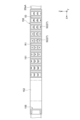
- FIG. 2 is a schematic diagram showing a side of a module body constituting an energy storage module.
- FIG. 3 is a schematic cross-sectional view of an example of a module body. Note that FIG. 2 shows the outer side surface 20sA of the module body 1A, and FIG. 3 shows a cross-section along line III-III in FIG. 2.
- the electrode stack 10 includes multiple electrodes stacked along the Z-axis direction. The Z-axis direction is the stacking direction of the electrodes, which is the height direction of the energy storage module 1.
- the multiple electrodes include multiple bipolar electrodes 11, a positive terminal electrode 12, and a negative terminal electrode 13. Separators 14 are interposed between adjacent electrodes.
- the bipolar electrode 11 has a collector 15, a positive electrode active material layer 16, and a negative electrode active material layer 17.
- the collector 15 is rectangular when viewed from the Z-axis direction and has a sheet shape.
- the active material layers (positive electrode active material layer 16, negative electrode active material layer 17) are provided in the center of the collector 15 when viewed from the Z-axis direction, and are not provided on the peripheral portion 15c of the collector 15.
- the negative electrode active material layer 17 is provided on the other surface 15b of the collector 15.
- the multiple bipolar electrodes 11 are stacked so that the positive electrode active material layer 16 of one bipolar electrode 11 and the negative electrode active material layer 17 of the other bipolar electrode 11 adjacent to each other in the stacking direction face each other.
- one surface 15a of the collector 15 is the surface facing one side in the Z-axis direction (the side where the negative electrode terminal electrode 13 is arranged in FIG. 3).
- the other surface 15b of the current collector 15 faces the other side in the Z-axis direction (the side where the positive terminal electrode 12 is located in FIG. 3).
- the positive electrode active material layer 16 and the negative electrode active material layer 17 are rectangular when viewed from the Z-axis direction.
- the negative electrode active material layer 17 is slightly larger than the positive electrode active material layer 16 when viewed from the Z-axis direction. In a plan view viewed from the Z-axis direction, the entire formation area of the positive electrode active material layer 16 is located within the formation area of the negative electrode active material layer 17.
- the positive electrode terminal electrode 12 has a current collector 15 and a positive electrode active material layer 16 provided on one surface 15a of the current collector 15.
- the positive electrode terminal electrode 12 does not have a positive electrode active material layer 16 or a negative electrode active material layer 17 on the other surface 15b of the current collector 15. In other words, no active material layer is provided on the other surface 15b of the current collector 15 of the positive electrode terminal electrode 12.
- the positive electrode terminal electrode 12 is laminated on the bipolar electrode 11 at one end of the electrode laminate 10 in the Z-axis direction.
- the positive electrode terminal electrode 12 is laminated on the bipolar electrode 11 so that the positive electrode active material layer 16 faces the negative electrode active material layer 17 of the bipolar electrode 11.
- the negative terminal electrode 13 has a current collector 15 and a negative active material layer 17 provided on the other surface 15b of the current collector 15.
- the negative terminal electrode 13 does not have a positive active material layer 16 or a negative active material layer 17 on one surface 15a of the current collector 15. In other words, no active material layer is provided on one surface 15a of the current collector 15 of the negative terminal electrode 13.
- the negative terminal electrode 13 is laminated on the bipolar electrode 11 at the end of the other side opposite to the one side on which the positive terminal electrode 12 is provided in the Z-axis direction of the electrode laminate 10.
- the negative terminal electrode 13 is laminated on the bipolar electrode 11 so that the negative active material layer 17 faces the positive active material layer 16 of the bipolar electrode 11.
- the current collectors of the bipolar electrode 11, the positive terminal electrode 12, and the negative terminal electrode 13 are designated by the same reference numeral as the current collector 15, but the current collectors of the bipolar electrode 11, the positive terminal electrode 12, and the negative terminal electrode 13 may be the same as or different from each other.
- Separators 14 are disposed between adjacent bipolar electrodes 11, between the positive terminal electrode 12 and the bipolar electrode 11, and between the negative terminal electrode 13 and the bipolar electrode 11. Separators 14 are disposed between the positive electrode active material layer 16 and the negative electrode active material layer 17, and separate the positive electrode active material layer 16 and the negative electrode active material layer 17. Separators 14 allow charge carriers such as lithium ions to pass through while preventing short circuits caused by contact between adjacent electrodes.
- the current collector 15 is a chemically inactive electrical conductor for continuing to pass current through the positive electrode active material layer 16 and the negative electrode active material layer 17 during discharging or charging of the lithium ion secondary battery.
- the material of the current collector 15 is, for example, a metal material, a conductive resin material, or a conductive inorganic material.
- the conductive resin material include resins in which a conductive filler is added as necessary to a conductive polymer material or a non-conductive polymer material.
- the current collector 15 may have multiple layers. In this case, each layer of the current collector 15 may contain the above-mentioned metal material or conductive resin material.
- a coating layer may be formed on the surface of the current collector 15.
- the coating layer may be formed by a known method such as plating or spray coating.
- the current collector 15 may be, for example, in the form of a plate, foil (e.g., metal foil), film, or mesh. Examples of metal foil include aluminum foil, copper foil, nickel foil, titanium foil, and stainless steel foil.
- the current collector 15 may be an alloy foil or clad foil of the above metals.
- the thickness of the current collector 15 may be, for example, 1 ⁇ m to 100 ⁇ m.
- the current collector 15 is a foil in which aluminum foil and copper foil are integrated, or is an aluminum foil.
- the positive electrode active material layer 16 contains a positive electrode active material capable of absorbing and releasing charge carriers such as lithium ions.
- the positive electrode active material include lithium composite metal oxides having a layered rock salt structure, metal oxides having a spinel structure, polyanion compounds, and the like.
- the positive electrode active material may be any material that can be used in lithium ion secondary batteries.
- the positive electrode active material layer 16 may contain a plurality of positive electrode active materials.
- the positive electrode active material layer 16 contains olivine-type lithium iron phosphate (LiFePO 4 ) as a composite oxide.
- the negative electrode active material layer 17 contains a negative electrode active material capable of absorbing and releasing charge carriers such as lithium ions.
- the negative electrode active material may be any of a simple substance, an alloy, or a compound. Examples of the negative electrode active material include Li, carbon, and metal compounds.
- the negative electrode active material may be an element capable of being alloyed with lithium or a compound thereof. Examples of carbon include natural graphite, artificial graphite, hard carbon (hardly graphitizable carbon), and soft carbon (easily graphitizable carbon). Examples of artificial graphite include highly oriented graphite and mesocarbon microbeads. Examples of elements capable of being alloyed with lithium include silicon and tin.
- the negative electrode active material layer 17 contains graphite as a carbon-based material.
- Each of the positive electrode active material layer 16 and the negative electrode active material layer 17 may further contain, as necessary, a conductive assistant to increase electrical conductivity, a binder, an electrolyte (polymer matrix, ionically conductive polymer, electrolyte solution, etc.), an electrolyte supporting salt (lithium salt) to increase ionic conductivity, etc.
- the conductive assistant is added to increase the conductivity of each electrode (bipolar electrode 11, positive terminal electrode 12, negative terminal electrode 13).
- the conductive assistant is, for example, acetylene black, carbon black, graphite, etc.
- Binders include fluorine-containing resins such as polyvinylidene fluoride, polytetrafluoroethylene, and fluororubber, thermoplastic resins such as polypropylene and polyethylene, imide resins such as polyimide and polyamideimide, alkoxysilyl group-containing resins, acrylic resins such as acrylic acid or methacrylic acid, styrene-butadiene rubber (SBR), carboxymethyl cellulose, alginates such as sodium alginate and ammonium alginate, water-soluble cellulose ester crosslinked bodies, and starch-acrylic acid graft polymers. These binders can be used alone or in combination. Examples of the solvent that can be used include water and N-methyl-2-pyrrolidone (NMP).
- NMP N-methyl-2-pyrrolidone
- the separator 14 may be, for example, a porous sheet or nonwoven fabric containing a polymer that absorbs and retains an electrolyte.
- materials for the separator 14 include polypropylene, polyethylene, polyolefin, polyester, and the like.
- the separator 14 may have a single-layer structure or a multi-layer structure.
- the multi-layer structure may have, for example, a ceramic layer as an adhesive layer or a heat-resistant layer.
- the separator 14 may be impregnated with an electrolyte.
- the separator 14 may be composed of an electrolyte such as a polymer electrolyte or an inorganic electrolyte.
- Examples of the electrolyte impregnated in the separator 14 include a liquid electrolyte (electrolyte solution) containing a non-aqueous solvent and an electrolyte salt dissolved in the non-aqueous solvent, or a polymer gel electrolyte containing an electrolyte held in a polymer matrix.
- a liquid electrolyte electrolyte solution
- electrolyte salt dissolved in the non-aqueous solvent
- polymer gel electrolyte containing an electrolyte held in a polymer matrix.
- the electrolyte salt may be a known lithium salt such as LiClO4 , LiAsF6 , LiPF6 , LiBF4 , LiCF3SO3 , LiN( FSO2 ) 2 , or LiN( CF3SO2 ) 2 .
- the non-aqueous solvent may be a known solvent such as cyclic carbonates, cyclic esters, chain carbonates, chain esters, or ethers. Two or more of these known solvent materials may be used in combination.
- the sealing body 30 includes a sealing body 20 and a reinforcing member 50.
- the sealing body 20 is formed in a frame shape on the periphery of the electrode laminate 10 so as to surround the periphery of the electrode laminate 10 when viewed from the Z-axis direction.
- the sealing body 20 can be joined to each of the one surface 15a and the other surface 15b of the current collector 15 at the peripheral portion 15c of each current collector 15.
- the sealing body 20 can form an internal space S between the current collectors 15 adjacent in the Z-axis direction and can seal each of the internal spaces S.
- each internal space S contains an electrolyte (not shown).
- the sealing body 20 cooperates with the current collectors 15 adjacent in the Z-axis direction to define the internal space S in which the electrolyte is contained.
- the sealing body 20 can suppress the electrolyte contained in the internal space S from leaking out to the outside.
- the sealing body 20 can prevent air, moisture, etc. from entering the internal space S from the outside of the electrode stack 10.
- the sealing body 20 can prevent, for example, gas generated in each electrode due to a charge/discharge reaction, etc. from leaking to the outside of the energy storage module 1.
- the edge of the separator 14 is joined to the sealing body 20.
- the sealing body 20 contains an insulating material. Examples of materials for the sealing body 20 include various resin materials such as polypropylene, polyethylene, polystyrene, ABS resin, acid-modified polypropylene, acid-modified polyethylene, and acrylonitrile-styrene resin.
- the sealing body 20 of the example includes a plurality of sealing materials 21, a pair of end sealing materials 24, and a plurality of spacers 22.
- the sealing materials 21, the end sealing materials 24, and the spacers 22 may be frame-shaped members formed in a sheet shape.
- the sealing body 20 also has a welded end portion 23.
- the sealing material 21 is frame-shaped when viewed from the Z-axis direction, and is provided along the peripheral portion 15c of the current collector 15.
- the sealing material 21 is provided so as to extend from one surface 15a of the current collector 15 through the end face to the other surface 15b, and covers the peripheral portion 15c.
- the sealing material 21 has an inner portion that overlaps with the current collector 15 and an outer portion that is located outside the edge of the current collector 15 on one surface 15a and the other surface 15b of the current collector 15, respectively, when viewed from the Z direction, and the outer portions of the pair of sealing materials 21 adjacent to each other across the current collector 15 are connected to each other.
- the sealant 21 can be welded to at least one of the one surface 15a and the other surface 15b of the current collector 15. In this embodiment, the sealant 21 is welded to both the one surface 15a and the other surface 15b of the current collector 15.
- the end seal material 24 has a frame shape when viewed from the Z-axis direction, and is provided along the peripheral portion 15c of the current collector 15 that constitutes the positive terminal electrode 12 and the negative terminal electrode 13, respectively. Therefore, the end seal material 24 is arranged so as to sandwich the multiple seal materials 21 from the Z-axis direction.
- the end seal material 24 can be welded to at least one of the one surface 15a and the other surface 15b of the current collector 15.
- the end seal material 24 of this embodiment is welded to both the one surface 15a and the other surface 15b of the current collector 15.
- the spacer 22 has a frame shape when viewed from the Z-axis direction, and is arranged along the peripheral portion 15c of the current collector 15.
- the spacer 22 is arranged so as to be interposed between adjacent seal materials 21 in the Z-axis direction.
- the spacer 22 is also arranged so as to be interposed between adjacent seal materials 21 and end seal materials 24 in the Z-axis direction.
- the spacer 22 can maintain the distance between adjacent current collectors 15 in the Z-axis direction.
- seal materials 21, and end seal materials 24 define an internal space S between adjacent current collectors 15.
- the welded end 23 is formed by welding together and integrating the ends of the multiple seal materials 21, the pair of end seal materials 24, and the multiple spacers 22 that are opposite the internal space S.
- the welded end 23 has a frame shape that surrounds the electrode stack 10.
- the side of the welded end 23 opposite the internal space S extends along the Z-axis direction and constitutes the outer surface 20s of the sealing body 20.
- the sealing body 20 includes the outer surface 20s opposite the internal space S.
- the outer surface 20s may be formed as a flat surface.
- the sealing body 20 has a number of communication holes 27 that communicate with each of the multiple internal spaces S (see FIG. 3).
- the communication holes 27 are notched portions formed in the spacer 22, and are formed to penetrate the welded end portion 23.
- the communication holes 27 have one opening in the internal space S and the other opening on the outer surface 20s of the sealing body 20. In the illustrated example, an opening is formed on the outer surface 20sA.
- the reinforcing member 50 is formed so as to overlap the area of the outer surface 20sA where the communication holes 27 are formed.
- the reinforcing member 50 is molded into a predetermined shape to provide a plurality of liquid inlet ports that respectively communicate with the plurality of communication holes 27.
- the reinforcing member 50 is joined to the welded end portion 23.
- the reinforcing member 50 is integrally joined to the welded end portion 23 by injection molding.
- An example of the reinforcing member 50 includes a main body portion 51, a first overhang portion 55, and a second overhang portion 57.
- the main body 51 partially covers the outer surface 20sA.
- the main body 51 covers the outer surface 20sA so as to include the region R1 in which the multiple communication holes 27 are formed on the outer surface 20sA.
- the multiple communication holes 27 are each connected to the multiple internal spaces S.
- 30 communication holes 27 corresponding to the internal spaces of the 30 layers formed between each current collector 15 are arranged discretely in the X-axis direction and the Z-axis direction.
- the communication holes 27 corresponding to the internal spaces of the first to tenth layers are arranged at equal intervals along the X-axis direction with the positive terminal electrode 12 side as the base end, and the communication holes 27 corresponding to the internal spaces of the 11th to 20th layers and the communication holes 27 corresponding to the internal spaces of the 21st to 30th layers are arranged in order in the Z-axis direction below the internal spaces of the first to tenth layers.
- the main body 51 extends in a rectangular shape along the X-axis and Z-axis directions to cover the region R3 in which the 30 communication holes 27 are formed.
- the main body 51 is formed in a rectangular plate shape with a predetermined thickness in the Y-axis direction.
- the main body 51 has an opening 52 at a position corresponding to the communication hole 27.
- the main body 51 also has a protruding frame portion 53 (frame portion) that protrudes from the outer surface 20sA in the Y-axis direction (second direction) that intersects (is perpendicular to) the outer surface 20sA.
- the protruding frame portion 53 surrounds each of the openings 52 when viewed from the Y-axis direction, and functions as a partition wall that separates each of the openings 52.
- ten protruding frame portions 53 are arranged in the X-axis direction.
- the protruding frame portions 53 are used, as an example, when injecting electrolyte into each of the internal spaces S.
- the nozzle of an injection device is brought into close contact with the top surface of the protruding frame portions 53, and electrolyte is introduced from the nozzle into the spaces of each of the protruding frame portions 53. This makes it possible to inject electrolyte into the internal spaces S from the openings 52 and the communication holes 27.
- the first overhang portion 55 and the second overhang portion 57 are formed by connecting both ends of the main body portion 51 in the Z-axis direction.
- the first overhang portion 55 partially covers one edge of the welded end portion 23 in the Z-axis direction (the positive side in the Z-axis direction).
- the first overhang portion 55 partially covers the end seal material 24 joined to the positive terminal electrode 12.
- the edge 55a of the first overhang portion 55 extends from the edge of the welded end portion 23 to a position outside the inner edge 22a of the spacer 22 and the inner edge 21a of the seal material 21 when viewed from the Z-axis direction.
- the first overhang portion 55 may be formed in a rectangular plate shape having the same length as the main body portion 51 in the X-axis direction.
- the second overhang portion 57 partially covers the other edge of the welded end portion 23 in the Z-axis direction (negative side in the Z-axis direction).
- the second overhang portion 57 partially covers the end seal material 24 joined to the negative terminal electrode 13.
- the edge 57a of the second overhang portion 57 extends from the edge of the welded end portion 23 to a position outside the inner edge 22a of the spacer 22 and the inner edge 21a of the seal material 21 when viewed from the Z-axis direction.
- the second overhang portion 57 may be formed in a rectangular plate shape having the same length as the main body portion 51 in the X-axis direction.
- a conductive member functioning as a terminal for extracting current from the energy storage module 1 may be disposed and electrically connected to the one surface 15a of the current collector 15 of the positive terminal electrode 12 and the other surface 15b of the current collector 15 of the negative terminal electrode 13 that are exposed from the sealing body 20.
- the conductive member may be disposed between the multiple energy storage modules 1 and used to electrically connect the adjacent energy storage modules 1.
- the restraining load from the restraining members may be applied to the electrode stack 10 via the conductive member.
- a cooling flow path may be formed in the conductive member.
- the energy storage module 1 can be cooled by circulating a cooling medium through the cooling flow path formed in the conductive member.
- FIGS. 4 and 5 are schematic cross-sectional views showing an example of an energy storage module.
- FIG. 6 is a perspective view showing a connection portion between example cover members.
- FIG. 7 is a perspective view showing an example of a cover member.
- FIG. 4 is a cross-sectional view of the energy storage module 1 at a position where a first cover member 61 constituting the cover member 60 is provided
- FIG. 5 is a cross-sectional view of the energy storage module 1 at a position where a second cover member 71 constituting the cover member 60 is provided.
- the cover member 60 covers the outer surface 20sA of the sealing body 30 and is fixed to the sealing body 30.
- the first cover member 61 covers the area of the outer surface 20sA where the reinforcing member 50 is formed.
- the second cover member 71 covers the area of the outer surface 20sA where the reinforcing member 50 is not formed.
- the first cover member 61 includes an attachment member 62 fixed to the sealing body 30, and a cover body 65 fixed to the attachment member 62.
- the attachment member 62 may be a resin member formed into a substantially rectangular plate shape.
- the size of the attachment member 62 in the Z-axis direction may be the same as the size of the reinforcing member 50 in the Z-axis direction.
- the size of the attachment member 62 in the X-axis direction may be the same as the size of the reinforcing member 50 in the X-axis direction.
- the mounting member 62 may be welded to the top surface of the protruding frame portion 53. By welding the mounting member 62 to the protruding frame portion 53, each of the 30 openings 52 separated by the protruding frame portion 53 is sealed.
- the mounting member 62 has groove portions 63 formed along the X-axis direction on both end faces in the Z-axis direction. A region 62a of the mounting member 62 closer to the module main body 1A than the groove portions 63 may be the same size as the reinforcing member 50 in the Z-axis direction. A region 62b of the mounting member 62 farther from the module main body 1A than the groove portions 63 may be smaller than the reinforcing member 50 in the Z-axis direction.
- the cover body 65 of one example clamps the mounting member 62 from the Z-axis direction.
- the cover body 65 includes a first wall portion 66 and a second wall portion 67 that face each other in the Z-axis direction, and a third wall portion 68 that extends in the XZ plane to connect the first wall portion 66 and the second wall portion 67.
- the connection portion 68a between the first wall portion 66 and the third wall portion 68 and the connection portion 68b between the second wall portion 67 and the third wall portion 68 are formed in a chamfered shape such that the corners are chamfered.
- the chamfered shape may be a C-chamfered shape or an R-chamfered shape (the illustrated example has a C-chamfered shape).
- the corners (connection portions 68a, 68b) formed by the connection between the walls may be formed to be inclined at an angle or may be formed to be rounded.
- the cover body 65 may be formed so that the interior is hollow to reduce weight.
- the hollow interior may have one or more reinforcing ribs 69.
- the rib 69 is plate-shaped extending along the YZ plane and connects the first wall portion 66 and the second wall portion 67 to each other.
- the rib 69 in the illustrated example is also connected to the third wall portion 68.
- the cover body 65 may have multiple ribs 69 at equal intervals in the X-axis direction.
- the position in the Y-axis direction of the end of the rib 69 opposite the third wall portion 68 may be separated from the mounting member 62 at the position where the engaging claws 66a, 67a described below are provided in order to ensure the amount of deflection of the first wall portion 66 and the second wall portion 67. Additionally, the end of the rib 69 opposite the third wall portion 68 may abut against the mounting member 62 so that the position of the cover body 65 in the Y-axis direction is restricted in a position where the locking claws 66a and 67a are not provided.
- the first wall portion 66 and the second wall portion 67 may each have a locking claw 66a, 67a.
- the first wall portion 66 and the second wall portion 67 have locking claws 66a, 67a that protrude toward each other at the end opposite the third wall portion 68.
- six locking claws 66a, 67a are formed at equal intervals in the X direction (see FIG. 1).
- the locking claws 66a, 67a engage with the groove portion 63 of the mounting member 62, so that the cover body 65 can clamp the mounting member 62 and be fixed to the mounting member 62.
- the cover body 65 is fixed to the sealing body 30 via the mounting member 62, and the first cover member 61 is fixed to the sealing body 30.
- multiple slits 64 extending in the Y-axis direction are formed at the ends of the first wall portion 66 and the second wall portion 67 opposite the third wall portion 68 (see FIG. 1), which makes it easier for the locking claws 66a, 67a to bend in the Z-axis direction.
- the slits 64 may be formed to sandwich the locking claws 66a, 67a, for example.
- the example second cover member 71 unlike the first cover member 61, does not have an attachment member and is fixed directly to the module main body 1A.
- the example second cover member 71 includes a first wall portion 76 and a second wall portion 77 that face each other in the Z axis direction, and a third wall portion 78 that extends in the XZ plane to connect the first wall portion 76 and the second wall portion 77.
- a connection portion 78a between the first wall portion 76 and the third wall portion 78, and a connection portion 78b between the second wall portion 77 and the third wall portion 78 are each formed in a chamfered shape, similar to the cover main body 65 of the first cover member 61.
- the second cover member 71 may be formed so that the inside is hollow to reduce weight.
- the hollow interior may have one or more reinforcing ribs 79.
- the rib 79 is plate-shaped extending along the YZ plane and connects the first wall portion 76 and the second wall portion 77 to each other.
- the rib 79 in the illustrated example is also connected to the third wall portion 78.
- the second cover member 71 may have multiple ribs 79 at equal intervals in the X-axis direction (see FIG. 7).
- the position in the Y-axis direction of the end of the rib 79 opposite the third wall portion 78 may be separated from the sealing body portion 20 at the position where the protrusions 76a and 77a described below are provided in order to ensure the amount of deflection of the first wall portion 76 and the second wall portion 77. Furthermore, the end of the rib 79 opposite the third wall portion 78 may abut against the sealing body 20 so that the position of the second cover member 71 in the Y-axis direction is restricted in a position where the protrusions 76a and 77a are not provided.
- the first wall portion 76 and the second wall portion 77 may have protrusions 76a, 77a, respectively.
- the first wall portion 76 and the second wall portion 77 have protrusions 76a, 77a facing each other at the end opposite the third wall portion 78.
- three protrusions are formed at equal intervals in the X direction.
- the protrusions 76a, 77a sandwich the sealing main body portion 20, so that the second cover member 71 can be fixed to the sealing body 30.
- a plurality of slits 74 see FIG.
- the slits 74 may be formed to sandwich the protrusions 76a, 77a, for example.
- the protrusions 76a, 77a may be engaged with both end surfaces in the Z-axis direction of the welded end 23 (see FIG. 3).
- the welded end 23 may or may not have a recess or the like for the protrusions 76a, 77a to engage with. If the welded end 23 does not have a recess or the like, the protrusions 76a, 77a can bend and pinch the welded end 23, thereby fixing the second cover member 71 to the welded end 23.
- FIG. 6 shows a recess 83 provided in the cover body 65 of the first cover member 61 and a locking claw 81 provided in the second cover member 71.
- the first cover member 61 and the second cover member 71 are connected to each other by the locking claw 81 and a recess 83 corresponding to the locking claw 81.
- the example second cover member 71 has a locking claw 81 protruding in the X-axis direction from the first wall portion 76 and the second wall portion 77.
- a recess 83 recessed in the Z-axis direction to correspond to the locking claw 81 is formed in the first wall portion 66 and the second wall portion 67 of the cover body 65 of the first cover member 61.
- the first cover member 61 may have a recess 83 that corresponds to the locking claw 81 of one second cover member 71, and a locking claw 81 that corresponds to the recess 83 of the other second cover member 71 (see FIG. 1).
- the cover body 65 and the second cover member 71 are connected by engaging the locking claw 81 of the second cover member 71 with the recess 83 of the cover body 65.
- the first wall portion 66, the second wall portion 67, and the third wall portion 68 of the cover body 65 are flush with the first wall portion 76, the second wall portion 77, and the third wall portion 78 of the second cover member 71, respectively. Also, as shown in FIG.
- the first wall portion 66 of the cover body 65, the region 62a of the mounting member 62 close to the module body 1A, and the first overhang portion 55 of the reinforcing member 50 may be flush with each other, and the second wall portion 67 of the cover body 65, the region 62a of the mounting member 62, and the second overhang portion 57 of the reinforcing member 50 may be flush with each other.
- the positions of the ends 76e, 77e of the first wall portion 76 and the second wall portion 77 of the second cover member 71 opposite the third wall portion 78 may be the same as the positions of the edge 55a of the first overhang portion 55 and the edge 57a of the second overhang portion 57 (see FIG. 4).
- the exterior film 90 shown in Figures 4 and 5 may be, for example, a laminate film including a metal layer. That is, the exterior film 90 may be a sheet-like member in which at least a portion of a metal layer such as aluminum is covered with a resin layer.
- the exterior film 90 surrounds and accommodates the entire module body 1A and the cover member 60. As a result, the cover member 60 is interposed between the sealing body 30 of the module body 1A and the exterior film 90. In this configuration, the outer surface 20sA of the module body 1A on which the liquid injection port is provided is not in contact with the exterior film 90.
- the metal layers of the exterior film 90 that are interposed between the positive terminal electrode 12 and the conductive member, and between the negative terminal electrode 13 and the conductive member, respectively, may be exposed from the resin layer. This allows current to be extracted from the energy storage module 1 using the conductive member.
- the entire metal layer of the exterior film 90 may be covered with a resin layer, and then current may be extracted from the energy storage module 1 by terminals connected to the positive terminal electrode 12 and the negative terminal electrode 13.
- the example energy storage module 1 includes an electrode stack 10 in which multiple electrodes, each including a current collector 15, are stacked in the Z-axis direction, a sealing body 30 that is provided on the electrode stack 10 so as to surround the electrode stack 10 when viewed from the Z-axis direction and is configured to seal multiple internal spaces S formed between adjacent current collectors 15 in the Z-axis direction, an exterior film 90 that surrounds and houses the electrode stack 10 and the sealing body 30, and a cover member 60 that is housed in the exterior film 90 so as to be interposed between the sealing body 30 and the exterior film 90, covers the outer surface 20s of the sealing body 30 extending in the Z-axis direction, and is fixed to the sealing body 30.
- a cover member 60 is interposed between the sealing body 30 and the exterior film 90, and the cover member 60 is fixed not to the electrode stack 10 but to the sealing body 30 that surrounds the electrode stack 10. In this way, since the cover member 60 is not directly fixed to the electrode stack 10, deformation and damage to the electrode stack 10 caused by the cover member 60 is suppressed. Also, in the above example, the cover member 60 that may come into contact with the exterior film 90 has connection portions 68a, 68b formed in a chamfered shape, so damage to the exterior film 90 is suppressed.
- the sealing body 30 in one example may have a plurality of communication holes 27 formed to communicate with each of the plurality of internal spaces S and to have an opening 52 on the side surface, and a protruding frame portion 53 protruding in the Y-axis direction from the outer side surface 20sA so as to surround each opening 52 of the plurality of communication holes 27, and the cover member 60 may cover the protruding frame portion 53.
- the protruding frame portion 53 is prevented from coming into contact with the exterior film 90, so that deformation and damage of the exterior film 90 due to the protruding frame portion 53 is prevented.
- wrinkles are less likely to form in the exterior film 90, so that damage to the exterior film 90 when the energy storage module 1 expands and contracts is prevented.
- the cover member 60 may be fixed to the protruding frame portion 53.
- the protruding frame portion 53 is prevented from coming into contact with the exterior film 90.
- the concept of fixing may include welding, clamping adhesion, and the like.
- the cover member 60 is welded to the protruding frame portion 53.
- the cover member 60 is fixed by clamping the protruding frame portion 53 from the Z-axis direction, it is conceivable that the protruding frame portion 53 will deform over time.
- the cover member 60 is welded to the protruding frame portion 53, deformation of the protruding frame portion 53 is prevented.
- An example of the cover member 60 may include an attachment member 62 welded to the protruding frame portion 53, and a cover body 65 that clamps the attachment member 62 from the Z-axis direction.
- the attachment member 62 as a dedicated part that is welded to the protruding frame portion 53, it is possible to reliably seal the protruding frame portion 53.
- the cover member 60 may be composed of a first cover member 61 that covers a region R1 of the outer surface 20sA where the protruding frame portion 53 is formed, and a second cover member 71 that covers a region R2 of the outer surface 20sA where the protruding frame portion 53 is not formed, and the first cover member 61 and the second cover member 71 may be connected to each other.
- the outer surface 20sA can be easily covered. Also, by dividing the cover member into multiple parts, the occurrence of warping or the like in each cover member is suppressed.
- the positions of the ends 76e, 77e of the first wall portion 76 and the second wall portion 77 of the second cover member 71 are the same as the positions of the edge 55a of the first overhang portion 55 and the edge 57a of the second overhang portion 57, so that the formation of a step between the second cover member 71 and the overhang portion is suppressed.
- wrinkles are less likely to form in the exterior film 90, so that damage to the exterior film 90 when the energy storage module 1 expands and contracts is suppressed.
- FIG. 8 is a schematic cross-sectional view of another example of a storage module.
- FIG. 8 is a cross-sectional view of the storage module at a position where a first cover member 161 is provided as a modified example of the first cover member 61.
- the exterior film 90 is omitted.
- the first cover member 161 may have a substantially rectangular plate shape.
- the size of the first cover member 161 in the Z-axis direction may be the same as the size of the reinforcing member 50 in the Z-axis direction.
- the size of the first cover member 161 in the X-axis direction may be the same as the size of the reinforcing member 50 in the X-axis direction.
- the first cover member 161 does not have an attachment member, and is welded to the reinforcing member 50.
- the first cover member 161 is welded to the protruding frame portion 53 of the reinforcing member 50.
- the first cover member 161 may be formed to be hollow on the inside like the cover body 65, or may not have a space on the inside.
- FIG. 9 is a schematic cross-sectional view of a further example of a storage module.
- FIG. 9 is a cross-sectional view of the storage module at a position where a second cover member 171 is provided as a modified example of the second cover member 71.
- the exterior film 90 is omitted.
- the second cover member 171 may have a pair of protruding pieces 172 protruding in the Y-axis direction from both ends in the Z-axis direction. With the sealing body 20 inserted between the protruding pieces 172, the outer surface 20s and the side surface 171b of the second cover member 171 facing the outer surface 20s are welded. In this state, the position of the end 172a of the protruding piece 172 may be the same as the position of the edge 55a of the first overhang portion 55 and the edge 57a of the second overhang portion 57 (see FIG. 4).
- FIG. 10 is a schematic cross-sectional view of a further example of a storage module.
- FIG. 10 is a cross-sectional view of the storage module at a position where a second cover member 271 is provided as a modified example of the second cover member 71.
- the exterior film 90 is omitted.
- the second cover member 271 has a first wall portion 276 and a second wall portion 277 facing each other in the Z-axis direction, a third wall portion 278 extending in the XZ plane to connect the first wall portion 276 and the second wall portion 277, and a reinforcing rib 279.
- the first wall portion 276 and the second wall portion 277 may have locking claws 276a, 277a, respectively.
- first wall portion 276 and the second wall portion 277 have locking claws 276a, 277a protruding to face each other at the end opposite the third wall portion 278.
- grooves 223 are formed along the X-axis direction on both end faces of the sealing body 20 in the Z-axis direction, and the second cover member 271 may be fixed to the sealing body 20 by engaging the locking claws 276a and 277a with the grooves 223 and clamping the sealing body 20.
- the exterior film 90 is not limited to a laminate film made of a metal layer and a resin layer.
- the exterior film 90 may be a laminate film made of a resin film that does not include a metal layer.
- Such a resin film may be composed of a resin layer with low moisture permeability.
- the interior of the exterior film 90 may be sealed in a reduced pressure state.
- the exterior film 90 is pressed by atmospheric pressure and adheres closely to the module body 1A.
- protruding parts of the sealing body 30, such as the protruding frame portion 53 may damage the exterior film 90, but the provision of the cover member 60 can prevent such damage.
- the three outer sides 20s other than the outer side 20sA on which the protruding frame portion 53 is not provided may be covered by a cover member similar to the second cover member 71.
- a cover member may be provided only on the outer side 20s arranged opposite the outer side 20sA, a cover member may be provided on one or both of the two outer sides 20s perpendicular to the outer side 20sA, or a cover member may be provided on all three outer sides 20s.
- the cover member may cover the entire surface or a part of the outer side 20s.
- the outer surface 20sA may be covered only by the second cover members.
- the extensions may be configured to have an outer shape similar to that of the first cover member 61 and cover the protruding frame portion 53.
- the opening of the protruding frame portion 53 may be sealed with a sealing film or the like.
- Fig. 11 is a schematic diagram showing a side view of a module body constituting a further energy storage module.
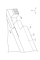
- Fig. 12 is a perspective view showing a portion of the side view of the module body of Fig. 11.
- Fig. 13 is a perspective view showing a cover member of another example.
- Fig. 14 is a perspective view showing the cover member of Fig. 13 attached to the module body.
- Fig. 15 is a cross-sectional view taken along line XV-XV of Fig. 14.
- the reinforcing member 150 has a main body portion 151 that partially covers the outer surface 20sA.
- the main body portion 151 has a protruding frame portion 53 similar to the main body portion 51 described above.
- the reinforcing member 150 also includes a terminal portion 152 for voltage detection.
- the terminal portion 152 is formed in the main body portion 151 at a position shifted toward the positive side in the X-axis direction from the multiple protruding frame portions 53.
- the terminal portion 152 can provide multiple terminals that are electrically connected to the multiple current collectors 15, respectively.
- a connector unit 152a (see FIG. 12) that is electrically connected to the multiple terminals can be fixed to the terminal portion 152.
- an engagement portion 155 that engages with the cover member 370 is formed at a position shifted toward the positive side in the X-axis direction from the terminal portion 152.
- the engagement portion 155 is formed at the end of the main body 151 in the X-axis direction.
- the engagement portion 155 may be fitted into the cover member 370.
- An example of the engagement portion 155 protrudes from the main body 151 in the Y direction.
- the engagement portion 155 has a central portion 155a extending along the Z-axis direction, and a pair of side portions 155b, 155c connected to both ends of the central portion 155a in the Z-axis direction.
- the side portions 155b, 155c extend toward the positive side in the X-axis direction from the central portion 155a as a base end.
- the distance L1 along the Z-axis direction from the top surface of the upper side portion 155b to the bottom surface of the lower side portion 155c is shorter than the length L2 of the main body portion 151 in the Z-axis direction.
- the cover member 370 includes a first wall portion 371 and a second wall portion 372 that face each other in the Z-axis direction, and a third wall portion 373 that extends in the XZ plane to connect the first wall portion 371 and the second wall portion 372.
- the cover member 370 also includes a fourth wall portion 374 and a fifth wall portion 375 that face each other in the X-axis direction and extend in the YZ plane to connect the first wall portion 371, the second wall portion 372, and the third wall portion 373.
- the connection portion between the third wall portion 373 and the fifth wall portion 375 is curved in an arc shape from the Z-axis direction.
- the corners 370k that connect the first wall portion 371 and the second wall portion 372 to the third wall portion 373 and the fourth wall portion 374 are formed in an indented shape.
- One or more reinforcing ribs 377 are provided inside the hollow cover member 370.
- the ribs 377 are plate-shaped extending along the YZ plane and connect the first wall portion 371, the second wall portion 372, and the third wall portion 373 to each other.
- the multiple ribs 377 may be arranged at equal intervals in the X-axis direction. As an example, the interval between adjacent ribs 377 is greater than the interval between the first wall portion 371 and the second wall portion 372.
- the first wall portion 371, the second wall portion 372, the fourth wall portion 374, the fifth wall portion 375, and the end faces of the ribs 377 facing away from the third wall portion 373 form a wall surface 379 facing the third wall portion 373.
- the first wall 371 and the second wall 372 are formed with a notch 378 near the fourth wall 374 to avoid interference with the end of the reinforcing member 150.
- the notch 378 is formed by recessing the wall surface 379 in the Y-axis direction toward the third wall 373.
- resin may protrude from the main body 151 of the reinforcing member 150 along the outer surface 20sA. In that case, the protruding resin portion may be accommodated in the space formed by the notch 378.
- the distance L3, which is the inside dimension between the first wall portion 371 and the second wall portion 372, may be the same as the distance L1, which is the outside dimension between the pair of side portions 155b, 155c of the engagement portion 155.
- distance L3 and distance L1 do not need to be exactly the same, as long as they are substantially the same.
- distance L3 in the cover member 370 in an unengaged state may be the same as distance L1 or slightly smaller.
- the outside dimension L4 between the first wall portion 371 and the second wall portion 372 may be the same as the length L2 of the main body portion 151 in the Z-axis direction.
- the cover member 370 is engaged with the engagement portion 155 formed on the main body portion 151 of the reinforcing member 150.
- the cover member 370 is engaged with the engagement portion 155 by fitting a pair of side portions 155b, 155c of the engagement portion 155 between the first wall portion 371 and the second wall portion 372.
- the first wall portion 371 and the second wall portion 372 may be flush with the first overhang portion 55 and the second overhang portion 57, respectively.
- the outer surface 20sA has the engaging portion 155 that engages with the cover member 370, so that the cover member 370 can be stably attached to the module main body 1A. Furthermore, since the engaging portion 155 is formed on the reinforcing member 150, excessive load is prevented from being applied to the welded end portion 23. Although an example in which the engaging portion 155 protrudes in the Y-axis direction has been shown, for example, a recess that is recessed in the Y-axis direction may be formed on the reinforcing member 150, and a protrusion that fits into the recess may be formed on the cover member. Furthermore, the cover member 370 and the engaging portion 155 may further have claws that engage with each other.
- the engaging portion 155 may be fitted between the walls that face each other in the X-axis direction.
- the cover member 370 may have a pair of ribs 377 to sandwich the engaging portion 155 from the X-axis direction.
- the engagement portion 155 may have a pair of side portions that extend along the YZ plane so as to abut against a pair of ribs 377.
- 1...energy storage module 10...electrode laminate, 11...bipolar electrode (electrode), 12...positive terminal electrode (electrode), 13...negative terminal electrode (electrode), 15...current collector, 20s...outer surface (side surface), 27...communicating hole, 50...reinforcing member, 53...protruding frame portion (frame portion), 60...cover member, 61...first cover member, 71...second cover member, 90...exterior film, S...internal space.
Landscapes
- Engineering & Computer Science (AREA)
- Chemical & Material Sciences (AREA)
- Chemical Kinetics & Catalysis (AREA)
- Electrochemistry (AREA)
- General Chemical & Material Sciences (AREA)
- Manufacturing & Machinery (AREA)
- Power Engineering (AREA)
- Microelectronics & Electronic Packaging (AREA)
- Sealing Battery Cases Or Jackets (AREA)
Priority Applications (2)
| Application Number | Priority Date | Filing Date | Title |
|---|---|---|---|
| CN202380088424.5A CN120418997A (zh) | 2023-01-23 | 2023-11-29 | 蓄电模块 |
| JP2024572863A JPWO2024157601A1 (https=) | 2023-01-23 | 2023-11-29 |
Applications Claiming Priority (2)
| Application Number | Priority Date | Filing Date | Title |
|---|---|---|---|
| JP2023008161 | 2023-01-23 | ||
| JP2023-008161 | 2023-01-23 |
Publications (1)
| Publication Number | Publication Date |
|---|---|
| WO2024157601A1 true WO2024157601A1 (ja) | 2024-08-02 |
Family
ID=91970291
Family Applications (1)
| Application Number | Title | Priority Date | Filing Date |
|---|---|---|---|
| PCT/JP2023/042778 Ceased WO2024157601A1 (ja) | 2023-01-23 | 2023-11-29 | 蓄電モジュール |
Country Status (3)
| Country | Link |
|---|---|
| JP (1) | JPWO2024157601A1 (https=) |
| CN (1) | CN120418997A (https=) |
| WO (1) | WO2024157601A1 (https=) |
Citations (3)
| Publication number | Priority date | Publication date | Assignee | Title |
|---|---|---|---|---|
| JP2020013637A (ja) * | 2018-07-13 | 2020-01-23 | 日産自動車株式会社 | 電池 |
| JP2020035665A (ja) * | 2018-08-30 | 2020-03-05 | 株式会社豊田自動織機 | 供給装置 |
| JP2020140881A (ja) * | 2019-02-28 | 2020-09-03 | 株式会社豊田自動織機 | 蓄電モジュールの製造装置及び製造方法 |
-
2023
- 2023-11-29 WO PCT/JP2023/042778 patent/WO2024157601A1/ja not_active Ceased
- 2023-11-29 JP JP2024572863A patent/JPWO2024157601A1/ja active Pending
- 2023-11-29 CN CN202380088424.5A patent/CN120418997A/zh active Pending
Patent Citations (3)
| Publication number | Priority date | Publication date | Assignee | Title |
|---|---|---|---|---|
| JP2020013637A (ja) * | 2018-07-13 | 2020-01-23 | 日産自動車株式会社 | 電池 |
| JP2020035665A (ja) * | 2018-08-30 | 2020-03-05 | 株式会社豊田自動織機 | 供給装置 |
| JP2020140881A (ja) * | 2019-02-28 | 2020-09-03 | 株式会社豊田自動織機 | 蓄電モジュールの製造装置及び製造方法 |
Also Published As
| Publication number | Publication date |
|---|---|
| CN120418997A (zh) | 2025-08-01 |
| JPWO2024157601A1 (https=) | 2024-08-02 |
Similar Documents
| Publication | Publication Date | Title |
|---|---|---|
| JP7711772B2 (ja) | 蓄電モジュール | |
| US20260058339A1 (en) | Method for manufacturing power storage module, and power storage module | |
| KR101821488B1 (ko) | 전지 | |
| CN119678299A (zh) | 蓄电模块和蓄电模块的制造方法 | |
| WO2024053231A1 (ja) | 蓄電モジュール | |
| US20240006666A1 (en) | Power storage device | |
| US20250105452A1 (en) | Electric power storage module | |
| JP7810095B2 (ja) | 蓄電モジュール | |
| US20260094943A1 (en) | Power storage module and power storage device | |
| JP2022014715A (ja) | 二次電池 | |
| WO2024157601A1 (ja) | 蓄電モジュール | |
| JP2024120645A (ja) | 蓄電モジュール製造方法、及び、蓄電モジュール | |
| JP7772232B2 (ja) | 蓄電モジュール | |
| JP2025086115A (ja) | 蓄電装置 | |
| JP2025085977A (ja) | 蓄電モジュール | |
| JP7647886B2 (ja) | 蓄電装置 | |
| US20250105332A1 (en) | Secondary battery | |
| WO2025053143A1 (ja) | 蓄電モジュール | |
| WO2025234331A1 (ja) | 蓄電装置 | |
| CN120600877A (zh) | 包括支撑部的电芯 | |
| WO2025115451A1 (ja) | 蓄電モジュール | |
| KR20250143432A (ko) | 단자 보호 커버를 포함하는 배터리 모듈 및 이를 포함하는 배터리 팩 | |
| KR20240101187A (ko) | 전지셀 및 이를 포함하는 전지 모듈 | |
| KR20250032445A (ko) | 배터리 셀 | |
| JP2025112318A (ja) | 二次電池 |
Legal Events
| Date | Code | Title | Description |
|---|---|---|---|
| 121 | Ep: the epo has been informed by wipo that ep was designated in this application |
Ref document number: 23918556 Country of ref document: EP Kind code of ref document: A1 |
|
| WWE | Wipo information: entry into national phase |
Ref document number: 202380088424.5 Country of ref document: CN |
|
| WWE | Wipo information: entry into national phase |
Ref document number: 2024572863 Country of ref document: JP |
|
| WWP | Wipo information: published in national office |
Ref document number: 202380088424.5 Country of ref document: CN |
|
| NENP | Non-entry into the national phase |
Ref country code: DE |
|
| 122 | Ep: pct application non-entry in european phase |
Ref document number: 23918556 Country of ref document: EP Kind code of ref document: A1 |