WO2024157478A1 - 香味スティック、非燃焼加熱式香味吸引製品、及び香味ロッドの製造方法 - Google Patents
香味スティック、非燃焼加熱式香味吸引製品、及び香味ロッドの製造方法 Download PDFInfo
- Publication number
- WO2024157478A1 WO2024157478A1 PCT/JP2023/002721 JP2023002721W WO2024157478A1 WO 2024157478 A1 WO2024157478 A1 WO 2024157478A1 JP 2023002721 W JP2023002721 W JP 2023002721W WO 2024157478 A1 WO2024157478 A1 WO 2024157478A1
- Authority
- WO
- WIPO (PCT)
- Prior art keywords
- flavor
- raw material
- outer wrapping
- rod
- wrapping paper
- Prior art date
- Legal status (The legal status is an assumption and is not a legal conclusion. Google has not performed a legal analysis and makes no representation as to the accuracy of the status listed.)
- Ceased
Links
Images






Classifications
-
- A—HUMAN NECESSITIES
- A24—TOBACCO; CIGARS; CIGARETTES; SIMULATED SMOKING DEVICES; SMOKERS' REQUISITES
- A24D—CIGARS; CIGARETTES; TOBACCO SMOKE FILTERS; MOUTHPIECES OF CIGARS OR CIGARETTES; MANUFACTURE OF TOBACCO SMOKE FILTERS OR MOUTHPIECES
- A24D1/00—Cigars; Cigarettes
- A24D1/20—Cigarettes specially adapted for simulated smoking devices
-
- A—HUMAN NECESSITIES
- A24—TOBACCO; CIGARS; CIGARETTES; SIMULATED SMOKING DEVICES; SMOKERS' REQUISITES
- A24C—MACHINES FOR MAKING CIGARS OR CIGARETTES
- A24C5/00—Making cigarettes; Making tipping materials for, or attaching filters or mouthpieces to, cigars or cigarettes
- A24C5/01—Making cigarettes for simulated smoking devices
-
- A—HUMAN NECESSITIES
- A24—TOBACCO; CIGARS; CIGARETTES; SIMULATED SMOKING DEVICES; SMOKERS' REQUISITES
- A24C—MACHINES FOR MAKING CIGARS OR CIGARETTES
- A24C5/00—Making cigarettes; Making tipping materials for, or attaching filters or mouthpieces to, cigars or cigarettes
- A24C5/14—Machines of the continuous-rod type
- A24C5/18—Forming the rod
-
- A—HUMAN NECESSITIES
- A24—TOBACCO; CIGARS; CIGARETTES; SIMULATED SMOKING DEVICES; SMOKERS' REQUISITES
- A24C—MACHINES FOR MAKING CIGARS OR CIGARETTES
- A24C5/00—Making cigarettes; Making tipping materials for, or attaching filters or mouthpieces to, cigars or cigarettes
- A24C5/14—Machines of the continuous-rod type
- A24C5/28—Cutting-off the tobacco rod
-
- A—HUMAN NECESSITIES
- A24—TOBACCO; CIGARS; CIGARETTES; SIMULATED SMOKING DEVICES; SMOKERS' REQUISITES
- A24F—SMOKERS' REQUISITES; MATCH BOXES; SIMULATED SMOKING DEVICES
- A24F40/00—Electrically operated smoking devices; Component parts thereof; Manufacture thereof; Maintenance or testing thereof; Charging means specially adapted therefor
- A24F40/30—Devices using two or more structurally separated inhalable precursors, e.g. using two liquid precursors in two cartridges
Definitions
- the present disclosure relates to methods for producing flavor sticks, non-combustion heating flavor inhalation products, and flavor rods.
- flavor sticks are known that are used in non-combustion flavor inhalers for inhaling flavors derived from a flavor source without combustion.
- One form of flavor stick is known, which includes a flavor rod formed by filling the inside of a cigarette paper with a filler material containing a flavor source (e.g., tobacco material) and an aerosol-generating base material (glycerin, propylene glycol, etc.), and a mouthpiece portion disposed behind the flavor rod (see, for example, Patent Document 1).
- a flavor source e.g., tobacco material
- an aerosol-generating base material glycerin, propylene glycol, etc.
- This type of flavor stick is used with a flavor inhalation device when inhaling.
- the flavor rod of the flavor stick is inserted into the heating chamber of the flavor inhalation device, and the flavor source of the flavor rod is heated without combustion by a heater of the non-combustion type flavor inhaler.
- This non-combustion heating causes an aerosol containing flavor components to be released from the flavor source, and the aerosol is inhaled by the user through the subsequent mouthpiece portion.
- an external heating method in which the flavor source of the flavor rod is heated from the outer periphery by a heater (external heater) arranged on the peripheral wall surface that defines the heating chamber.
- the objective of the present disclosure is to provide a flavor stick that is inhaled using a flavor inhalation device that uses an external heating method, and that includes a new flavor rod having multiple flavor sources.
- the flavor stick of the present disclosure for solving the above problems is a flavor stick comprising a flavor rod that is inserted into a heating chamber of a flavor inhalation device and heated from the outer circumferential side by an external heater arranged on the lateral periphery of the heating chamber, the flavor rod comprising an outer wrapping paper and a plurality of flavor molded bodies arranged inside the outer wrapping paper and molded into a predetermined shape, each of the plurality of flavor molded bodies being positioned and held on the inner surface of the outer wrapping paper.
- the flavor molded body according to aspect 1 may extend along the axial direction of the flavor rod.
- each of the plurality of flavor molded bodies may be adhered to the inner surface of the outer wrapping paper.
- the flavor rod may further include a partition paper that is arranged inside the outer wrapping paper and partitions the cross section of the flavor rod, and the multiple flavor molded bodies may be arranged in a flavor storage area formed between the outer wrapping paper and the partition paper.
- the partition paper divides the cross section of the flavor rod so that a plurality of flavor storage areas separated from each other are formed between the outer wrapping paper and the partition paper, and one or more of the flavor molded bodies may be contained in each of the plurality of flavor storage areas.
- the partition paper may be partially adhered to the inner surface of the outer wrapping paper, thereby partitioning the flavor containing regions from one another.
- the flavor molded bodies may be individually accommodated in the flavor accommodation region.
- the present disclosure can also be specified as a non-burning flavor inhalation product. That is, the non-burning flavor inhalation product according to the present disclosure includes a flavor stick as described above, a flavor inhalation device having a heating chamber into which the flavor rod can be inserted, and an external heater disposed on the periphery of the heating chamber.
- the present disclosure can also be specified as a method for producing a flavor rod. That is, the method for producing the above-mentioned flavor rod by a winding machine includes a winding step of placing a plurality of long flavor molded body raw material sheets in parallel on the upper surface of a long outer wrapping paper raw material sheet, and while conveying each of the flavor molded body raw material sheets in a state where each is positioned on the upper surface of the outer wrapping paper raw material sheet along a conveying path of the winding machine, winding up the outer wrapping paper raw material sheet into a cylindrical shape to form a long flavor rod, and a cutting step of cutting the long flavor rod to a predetermined length.
- each of the flavor molded body raw material sheets may be adhered to an upper surface of the outer wrapping paper raw material sheet.
- a long partition paper raw material sheet may be placed to cover the flavor molding raw material sheet placed on the upper surface of the outer wrapping paper raw material sheet, and the partition paper raw material sheet may be partially adhered to the upper surface of the outer wrapping paper raw material sheet, thereby positioning each of the flavor molding raw material sheets on the upper surface of the outer wrapping paper raw material sheet.
- a flavor stick that is inhaled using a flavor inhalation device that uses an external heating method, and that includes a new flavor rod having multiple flavor sources.
- FIG. 1 is a schematic diagram of a flavor inhalation device for heating a flavor stick without combustion according to a first embodiment.
- FIG. 2 is a diagram showing a schematic structure of a flavor stick according to embodiment 1.
- FIG. 3 is a view taken along the arrow A in FIG.
- FIG. 4 is a perspective view of a support portion according to the first embodiment.
- FIG. 5 is a diagram illustrating a manufacturing procedure of the flavor rod according to the first embodiment.
- FIG. 6 is a diagram illustrating a manufacturing procedure of the flavor rod according to the first embodiment.
- FIG. 7 is a diagram illustrating a method for folding the flavor molded body raw material.
- FIG. 1 is a schematic diagram of a flavor inhalation device for heating a flavor stick without combustion according to a first embodiment.
- FIG. 2 is a diagram showing a schematic structure of a flavor stick according to embodiment 1.
- FIG. 3 is a view taken along the arrow A in FIG.
- FIG. 4 is a perspective view of a
- FIG. 8 is a diagram illustrating an example of an application pattern of adhesive glue applied to the upper surface of the outer wrapping paper raw material sheet by the glue application device according to the first embodiment.
- FIG. 9 is a diagram illustrating the state immediately before the outer wrapping paper raw material sheet is rolled up into a cylindrical shape in the rolling process.
- FIG. 10 is a cross-sectional view of a flavor rod according to the second embodiment.
- FIG. 11 is a diagram illustrating a method for manufacturing a flavor rod according to the second embodiment.
- FIG. 12 is a diagram illustrating a method for manufacturing a flavor rod according to the second embodiment.
- FIG. 13 is a diagram illustrating an example of an application pattern of adhesive glue applied to the upper surface of the outer wrapping paper raw material sheet by the glue application device according to the second embodiment.
- FIG. 14 is a cross-sectional view showing a state in which the partition paper raw material sheet is bonded to the outer wrapping paper raw material sheet.
- the flavor stick according to the present disclosure is a flavor stick that includes a flavor rod that is inserted into a heating chamber of a flavor inhalation device and heated from the outer peripheral side by an external heater disposed on the lateral periphery of the heating chamber.
- the flavor rod of the flavor stick includes an outer wrapping paper and a plurality of flavor molded bodies that are disposed inside the outer wrapping paper and molded into a predetermined shape. Each of the plurality of flavor molded bodies is positioned and held on the inner surface of the outer wrapping paper.
- Fig. 1 is a schematic diagram of a flavor inhalation device 30 for non-combustion heating of a flavor stick according to embodiment 1.
- Fig. 2 is a diagram showing a schematic structure of a flavor stick 1 according to embodiment 1.
- the flavor inhalation device 30 is an inhalation device used when inhaling the flavor stick 1, and the flavor stick 1 and the flavor inhalation device 30 constitute a non-combustion type flavor inhalation product.
- the flavor inhalation device 30 has a heating chamber 31 capable of accommodating the flavor rod 2 of the flavor stick 1, and the flavor rod 2 can be freely inserted and removed from its insertion opening 31A.
- the heating chamber 31 is a roughly cylindrical hollow portion defined by a chamber side peripheral wall 31B forming the side of the heating chamber 31 and a chamber bottom wall 31C forming the bottom of the heating chamber 31.
- An electric external heater 32 for heating the flavor rod 2 from the outer periphery is disposed on the chamber side peripheral wall 31B (side peripheral portion) of the heating chamber 31 of the flavor inhalation device 30.
- the flavor inhalation device 30 further includes a power supply unit 33, which is a power supply unit that supplies operating power to the external heater 32, and a control unit 34 that controls the power supply from the power supply unit 33 to the external heater 32.
- a power supply unit 33 which is a power supply unit that supplies operating power to the external heater 32
- a control unit 34 that controls the power supply from the power supply unit 33 to the external heater 32.
- One end of the air flow path 36 is connected to the chamber bottom wall 31C of the flavor inhalation device 30.
- the other end of the air flow path 35 is connected to an air intake port 37 formed in the housing of the flavor inhalation device 30.
- the manner in which external air is introduced into the heating chamber 31 of the flavor inhalation device 30 is not limited to the above example.
- a counter flow type air introduction means that introduces external air introduced from the insertion port 31A of the flavor inhalation device 30 into the bottom of the heating chamber 31 may be adopted.
- external air introduced from the insertion port 31A of the flavor inhalation device 30 may be supplied to the bottom side of the heating chamber 31 through the gap between the outer peripheral surface of the flavor stick 1 inserted into the heating chamber 31 and the chamber side peripheral wall 31B.
- the external heater 32 is a heating element, such as a metal thin film heater or a film heater, that generates heat using power supplied from the power supply unit 33.
- a metal thin film heater is a flexible planar heating heater that uses a metal thin film as a heating element.
- a film heater may have a structure in which, for example, a layer made of an electrically insulating material is layered on a layer made of a heating track, which is an example of a heating element.
- the type of external heater 32 is not particularly limited as long as it can heat the flavor rod 2 inserted into the heating chamber 31 from the outer periphery.
- the external heater 32 may be provided in a manner that allows it to face the outer periphery of the flavor rod 2 inserted into the heating chamber 31 from the front end to the rear end.
- the flavor stick 1 includes a flavor rod 2 that is inserted into a heating chamber 31 in the flavor inhalation device 30 and heated by the external heater 32, and a mouthpiece portion 3 that is connected to the rear end side of the flavor rod 2.
- the flavor stick 1 has, for example, a cylindrical rod shape that extends in one direction, as shown in FIG.
- the symbol CL denotes the central axis of the flavor stick 1. Since the flavor rod 2 and the mouthpiece portion 3 are coaxially arranged, the central axis CL can also be said to be the central axis of the flavor rod 2 and the mouthpiece portion 3.
- the direction in which the central axis CL extends is also referred to as the axial direction of the flavor rod 2 and the mouthpiece portion 3.
- the cylindrical rod-shaped flavor rod 2 and the mouthpiece portion 3 are arranged coaxially and are connected together by being wound coaxially with tipping paper 8.
- Reference numeral 1a denotes the mouth end 1a formed on the rear end side of the flavor stick 1
- reference numeral 1b denotes the front end of the flavor stick 1.
- the flavor stick 1 is inserted into the heating chamber 31 in the flavor inhalation device 30 from the front end 1b side.
- FIG. 3 is a view taken along the arrow A in FIG. 2, showing a front view of the flavor stick 1 (flavor rod 2) as viewed from the front end 1b side.
- the flavor rod 2 comprises an outer wrapping paper 21 and a plurality of flavor moldings 22 arranged inside the outer wrapping paper 21. Each of the flavor moldings 22 is positioned and held on the inner surface 21A of the outer wrapping paper 21.
- the flavor molded body 22 is a molded body containing a flavor source and molded into a predetermined shape.
- the flavor molded body 22 shown in FIG. 3 is a flavor source molded into a sheet shape and folded into a spiral shape, but the shape of the flavor molded body 22 is not particularly limited.
- three flavor molded bodies 22 are arranged inside the outer wrapping paper 21 of the flavor rod 2, but the number of flavor molded bodies 22 is not particularly limited as long as it is multiple.
- Each flavor molded body 22 is adhered to the inner surface 21A of the outer wrapping paper 21 by a molded body adhesive glue BD, and is thereby positioned and held on the inner surface of the outer wrapping paper 21.
- the molded body adhesive glue BD may extend from the front end 1b to the rear end of the flavor rod 2A.
- the flavor molded body 22 folded into a spiral shape extends along the central axis CL direction (axial direction) of the flavor rod 2.
- the number of flavor molded bodies 22 may be changed between the front end side and the rear end side of the flavor rod 2.
- the flavor molded body 22 may be configured to include, for example, tobacco shreds as a flavor source.
- the material of the tobacco shreds is not particularly limited, and known materials such as lamina and backbone can be used.
- the tobacco shreds may be made by crushing dried tobacco leaves to obtain tobacco shreds, homogenizing the shreds, and processing them into a sheet (hereinafter, simply referred to as a "homogenized sheet"), which is then shredded.
- the homogenized sheet may be manufactured by known methods such as a papermaking method, a slurry method, a rolling method, etc.
- various types of tobacco may be used for the flavor molded body 22.
- flavor sources exemplified above may be processed into, for example, a sheet form to form the flavor molded body 22.
- unshredded tobacco leaves may be used as the material for forming the flavor molded body 22.
- the flavor molded body 22 may contain a flavor as a flavor source.
- the type of flavor is not particularly limited.
- flavors include acetanisole, acetophenone, acetylpyrazine, 2-acetylthiazole, alfalfa extract, amyl alcohol, amyl butyrate, trans-anethole, star anise oil, apple juice, Peru balsam oil, beeswax absolute, benzaldehyde, benzoin resinoid, benzyl alcohol, benzyl benzoate, benzyl phenylacetate, benzyl propionate, 2,3-butanedione, 2-butanol, butyl butyrate, butyric acid, caramel, cardamom oil, carob absolute, ⁇ -carotene, carrot juice, L -Carvone, ⁇ -caryophyllene, cassia bark oil, cedarwood oil, celery seed oil, chamomile oil, cinnam
- the flavor molded body 22 may not contain tobacco materials.
- raw materials for such flavor molded body 22 include plant materials that do not contain tobacco components.
- the flavor molded body 22 may contain one or more selected from the leaf pulp, veins, stems, roots, flowers, seeds, and pulp of plants that do not contain tobacco components.
- Herbal materials can be suitably used as a flavor source as plant materials that do not contain tobacco components. Examples of herbal materials include allspice, black pepper, Ezo white root, calamus root, catnip, catuaba, cayenne pepper, chaga, chervil, cinnamon, ginseng, St.
- Some examples include menthe, oolong tea, oregano, pennyroyal, peppermint, red clover, rooibos (red or green), rose hips, rosemary, sage, clary sage, savory, spearmint, gotu kola, thyme, turmeric, valerian, wintergreen, yellow dock, yerba mate, yerba santa, bacopa monniera, ashwagandha, chili pepper, ground cherries, and milk thistle.
- the flavor molded body 22 may contain a mixture of tobacco material and herbal material as described above.
- the flavor molded body 22 in this embodiment contains an aerosol-generating substrate.
- the aerosol-generating substrate is a substance that generates an aerosol when the volatile substance released when vaporized by heating with the heater of the flavor inhalation device 30 is cooled.
- the aerosol-generating substrate is, for example, a liquid.
- the type of aerosol-generating substrate there are no particular limitations on the type of aerosol-generating substrate, and various extracts from natural products and/or their constituent components can be selected depending on the application.
- the aerosol-generating substrate include glycerin, propylene glycol, triacetin, 1,3-butanediol, and mixtures thereof.
- the flavor molded body 22 can be obtained by molding the above-mentioned raw materials using known molding techniques.
- the flavor molded body 22 may be a paper sheet, a cast sheet, or a rolled sheet formed by the above-mentioned papermaking method, slurry method, rolling method, etc.
- the mouthpiece section 3 has a support section 4, a cooling section 5, and a filter section 6 from the front end side.
- the support section 4, the cooling section 5, and the filter section 6 in the mouthpiece section 3 are aligned coaxially and are wound up together with the winding paper 7.
- the flavor stick 1 is formed by winding up the flavor rod 2 and the mouthpiece section 3 together with the tipping paper 8.
- the tipping paper 8 winds up the rear end side of the flavor rod 2 and the entire mouthpiece section 3 together.
- the flavor stick 1 may be formed by winding up the flavor rod 2, the support section 4, the cooling section 5, and the filter section 6 together with the tipping paper 8 without using the winding paper 7.
- the above-mentioned configuration of the mouthpiece section 3 is one example, and some of the configurations may not be included (for example, the support section 4 may be omitted).
- the support part 4 is a perspective view of the support part 4 according to the first embodiment.
- the support part 4 is a segment located immediately at the rear end side of the flavor rod 2 and arranged in contact with the rear end of the flavor rod 2.
- the symbol CL2 is the central axis of the support part 4.
- the support part 4 is a perforated columnar body having a through hole formed as an aerosol flow path 41 in the center of a cross section perpendicular to the central axis CL2.
- the support part 4 is a member for preventing the flavor molded body 22 located inside the outer wrapping paper 21 from being pushed into the mouthpiece part 3 side due to insertion resistance caused by friction between the chamber side peripheral wall 31B and the outer wrapping paper 21 when the flavor rod 2 is inserted into the heating chamber 31.
- the symbol 42 is a support surface located on the front end side of the support part 4.
- the support surface 42 is arranged on the outer periphery of the cross section of the mouthpiece part 3 and is in contact with, for example, the rear end of each flavor molded body 22 in the flavor rod 2.
- a portion of each flavor molded body 22 is arranged to face the aerosol flow path 41 of the support part 4. This allows the aerosol generated in each flavor molded body 22 to be efficiently introduced into the aerosol flow path 41 of the support part 4 when the flavor stick 1 is inhaled.
- the support part 4 can be made of various materials.
- the support part 4 may be a hollow cellulose acetate tube.
- the support part 4 may be a cylindrical cellulose acetate fiber bundle with a center hole formed through the center of the cross section.
- the material of the support part 4 is not particularly limited.
- the support part 4 also functions as a spacer for separating the cooling part 5 from the flavor rod 2.
- the cooling section 5 is a segment located immediately behind the support section 4 and in contact with the rear end of the support section 4.
- the volatile substances released from the flavor rod 2 (flavor molding 22) flow downstream along the cooling section 5.
- the volatile substances released from the flavor rod 2 (flavor molding 22) are cooled in the cooling section 5, which promotes the generation of aerosol.
- the cooling section 5 is formed by a hollow paper tube having an air hole 5A that can introduce outside air. However, the cooling section 5 does not have to have an air hole 5A.
- a cooling promotion material such as a polylactic acid sheet may be disposed in the paper tube forming the cooling section 5, and the cooling of the volatile substances released from the flavor rod 2 (flavor molding 22) may be promoted by the cooling promotion material.
- the cooling section 5 may have a heat absorbing agent arranged so as not to interfere with the flow of the volatile substances and aerosol.
- the cooling section 5 may include a filter material in which a number of flow paths (through holes) are formed along the longitudinal direction (axial direction) of the mouthpiece section 3.
- the cooling section 5 may also be a cellulose acetate tube in which a hollow through passage is formed in the axial direction.
- the filter section 6 is a segment located at the rear end of the mouthpiece section 3, i.e., on the mouth end 1a side.
- the filter section 6 may be located immediately behind the cooling section 5 and may be arranged in contact with the rear end of the cooling section 5.
- the filter section 6 may contain, for example, a filter material that collects a specific component contained in the aerosol.
- the type of filter material forming the filter section 6 is not particularly limited.
- the filter section 6 may be equipped with a filter material formed of cellulose acetate fibers formed into a cylindrical shape.
- the filter section 6 may also be a center hole filter in which a center hole is formed along the axial direction of the cellulose acetate fibers formed into a cylindrical shape.
- the filter section 6 may also be a paper filter filled with cellulose fibers, or a paper tube without a filter material.
- the filter section 6 may also be formed by selectively combining a solid filter material with a filter material, a center hole filter, a paper filter, and a paper tube without a filter material.
- the flavor stick 1 equipped with the flavor rod 2 configured as described above is inhaled using a flavor inhalation device 30 shown in FIG. 1.
- a flavor inhalation device 30 shown in FIG. 1.
- the external heater 32 is operated by supplying operating power from the power supply unit 33 to the external heater 32 based on a command signal from the control unit 34 of the flavor inhalation device 30.
- the control unit 34 may use this as a trigger to operate the external heater 32.
- the flavor inhalation device 30 may be provided with a sensor that detects the insertion of the flavor stick 1 (flavor rod 2) into the heating chamber 31.
- the control unit 34 may use the detection of the insertion of the flavor stick 1 (flavor rod 2) into the heating chamber 31 as a trigger to operate the external heater 32.
- the control unit 34 may be provided with a temperature sensor that detects the temperature in the heating chamber 31 or the temperature of the flavor rod 2, and may adjust the amount of current supplied from the power supply unit 33 to the external heater 32 based on the temperature detected by the temperature sensor.
- each flavor molded body 22 in the flavor rod 2 is heated, an aerosol containing flavor components (e.g., tobacco components) is released.
- the aerosol containing the flavor components generated by the flavor rod 2 passes through the mouthpiece section 3, the support section 4 (aerosol flow path 41), the cooling section 5, and the filter section 6 in sequence, and is finally inhaled by the user from the mouth end 1a.
- the flavor stick 1 employs a novel configuration that distinguishes it from the conventional configuration in that multiple flavor molded bodies 22 are positioned and held on the inner surface 21A of the outer wrapping paper 21 of the flavor rod 2.
- the flavor molded bodies 22 provided in the flavor rod 2 in this embodiment are molded bodies formed into a predetermined shape, and differ from the rod configuration in which a typical powdered, granular, or chopped flavor source is filled inside the wrapping paper of the conventional configuration. This prevents the flavor source from collapsing from the front end of the flavor rod as in the conventional configuration.
- the flavor molding 22 extends along the axial direction of the flavor rod 2. Therefore, the aerosol containing the flavor components released from the flavor molding 22 by heating with the heater of the flavor inhalation device 30 can easily flow smoothly along the axial direction of the flavor rod 2.
- each of the multiple flavor molded bodies 22 is adhered to the inner surface 21A of the outer wrapping paper 21, making it possible to more firmly position and hold each flavor molded body 22 relative to the inner surface 21A of the outer wrapping paper 21.
- the type of flavor source may be different between at least one of the multiple flavor moldings 22 and the other flavor moldings 22. This increases the degree of freedom in the flavor design of the flavor rod 2, making it easier to achieve a rich flavor.
- the types of flavor sources are different between the flavor moldings 22 in the flavor rod 2 as described above, the amount of flavor source blended according to the type may be changed.
- the flavor inhalation device 30 in this embodiment may be provided with multiple external heaters 32 for individually heating the multiple flavor moldings 22 included in the flavor rod 2.
- the flavor inhalation device 30 may be provided with a number of external heaters 32 corresponding to the number of flavor moldings 22 included in the flavor rod 2, and the multiple flavor moldings 22 may be individually heated at any independent timing.
- a single external heater 32 may have multiple heating regions that are independently heat-controlled, and each heating region may heat each flavor molded body 22 individually and independently at any desired timing.
- the outer wrapping paper 21 in the flavor rod 2 is preferably made of a material with high heat transfer performance in order to efficiently transfer heat from the external heater 32 to the flavor molded body 22 inside. Therefore, it is preferable to use a material with low basis weight and high density for the outer wrapping paper 21. For example, it is preferable to set the basis weight of the outer wrapping paper 21 to 10 gsm or more and 40 gsm or less, and the density of the outer wrapping paper 21 to 1 g/cm 3 or more and 1.5 g/cm 3 or less.
- the outer wrapping paper 21 may be coated with a coating agent such as pectin or sodium alginate in order to improve its heat transfer performance.
- a material with excellent heat transfer performance such as aluminum-laminated paper may be used as the outer wrapping paper 21.
- the above-mentioned specifications of the outer wrapping paper 21 are only examples, and are not limited to these.
- the static friction coefficient between the external heater 32 and the outer wrapping paper 21 is adjusted to be 0.45 to 0.75, and the dynamic friction coefficient is adjusted to be 0.4 to 0.7.
- the tensile strength of the outer wrapping paper 21 is 10 to 20 N/15 mm, and the wet tensile strength of the outer wrapping paper 21 is 5 to 20 N/15 mm.
- the method for measuring the tensile strength of the outer wrapping paper 21 complies with, for example, JIS P 8113.
- the method for measuring the wet tensile strength of the outer wrapping paper 21 is, for example, based on the wet tensile strength test described in JP 2019-187451 A.
- the manufacturing method for the flavor rod 2 includes a winding process and a cutting process.
- the winding process is a process in which multiple long flavor molded bodies are placed in parallel on the upper surface of a long outer wrapping paper, and each of the long flavor molded bodies is positioned on the upper surface of the long outer wrapping paper, and while transporting them along the transport path of the winding machine, the long outer wrapping paper is rolled up into a cylindrical shape to form a long flavor rod.
- the cutting process is a process in which the long flavor rod is cut to a predetermined length.
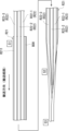
- FIGS. 5 and 6 are diagrams illustrating a method for manufacturing a flavor rod 2 according to embodiment 1.
- various raw materials for the flavor rod 2 are transported along the transport direction indicated by the arrows.
- Various raw materials for the flavor rod 2 are transported along a transport path on a conveyer such as a garniture belt of a winding machine.
- FIG. 5 is a top schematic diagram illustrating the process for manufacturing a flavor rod 2.
- FIG. 6 is a side schematic diagram illustrating the process for manufacturing a flavor rod 2.
- each flavor molding raw material sheet R22 is placed in parallel on the upper surface R211 of the outer wrapping paper raw material sheet R21.
- the outer wrapping paper raw material sheet R21 is a long strip-shaped paper sheet for forming the outer wrapping paper 21.
- the flavor molding raw material sheet R22 is a long strip-shaped raw material sheet for forming the flavor molding 22, and is folded (rolled) into a spiral shape in a manner similar to the flavor molding 22 described in Figure 3.
- Figure 5 shows an example in which three flavor molded body raw material sheets R22 are supplied onto the upper surface R211 of the outer wrapping paper raw material sheet R21.
- the three flavor molded body raw material sheets R22 are distinguished by the symbols R22-1 to R22-3.
- they may be simply referred to as flavor molded body raw material sheets R22.
- multiple flavor molding raw material sheets R22 are placed in parallel at intervals in the width direction of the outer wrapping paper raw material sheet R21, and each flavor molding raw material sheet R22 is adhered to the upper surface R211 of the outer wrapping paper raw material sheet R21.
- the adhesive glue for adhering each flavor molding raw material sheet R22 to the upper surface R211 of the outer wrapping paper raw material sheet R21 is applied to the upper surface R211 by a glue application device 70 shown in FIG. 6.
- the symbol B1 shown in FIG. 6 is a rotatable bobbin around which the outer wrapping paper raw material sheet R21 is wound.
- the outer wrapping paper raw material sheet R21 is sequentially unwound from the bobbin B1.
- the width direction of the various sheet materials that are the raw materials for the flavor rod 2 refers to the direction perpendicular to their longitudinal direction.
- the method of folding each flavor molded body raw material sheet R22 supplied onto the outer wrapping paper raw material sheet R21 is not particularly limited, but an example will be described with reference to FIG. 7.
- the sheet material R22' unwound from a rotatable bobbin B2 is transported by a conveyor or the like, and is folded (rolled) sequentially by a guide (not shown) to form a spirally folded flavor molded body raw material sheet R22.
- P1 to P3 in the figure are examples of folding positions of the sheet material R22'.
- the sheet material R22' is folded in three stages at folding positions P1 to P3, but this folding mode is one example.
- the left end of FIG. 7 shows a schematic cross-sectional shape of the flavor molded body raw material sheet R22 in a spirally folded state.
- the symbol S1 shown in FIG. 6 is a junction where multiple flavor molded body raw material sheets R22 are supplied to join onto the outer wrapping paper raw material sheet R21 being conveyed on the conveying path.
- a glue applicator 70 is disposed between the bobbin B1 and the junction S1 to apply adhesive glue to the upper surface R211 of the outer wrapping paper raw material sheet R21.
- the glue applicator 70 continuously applies adhesive glue in a rail shape (straight line) along the longitudinal direction of the upper surface R211 of the outer wrapping paper raw material sheet R21 unwound from the bobbin B1.
- FIG. 8 is a diagram illustrating an example of an application pattern of adhesive glue applied to the upper surface R211 of the outer wrapping paper raw material sheet R21 by the glue applicator 70 according to the first embodiment.
- FIG. 8 shows a cross section of the outer wrapping paper raw material sheet R21 to which adhesive glue has been applied by the glue applicator 70.
- the cross section here is a cross section perpendicular to the longitudinal direction of the sheet.
- the symbols BD1 to BD3 in FIG. 8 are adhesive pastes for molded bodies used to adhere each flavor molded body raw material sheet R22 to the upper surface R211 of the outer wrapping paper raw material sheet R21.
- the symbol BD0 is an adhesive paste for wrapping used to adhere a first end E1 in the width direction of the outer wrapping paper raw material sheet R21 to a second end E2 on the other end side when the outer wrapping paper raw material sheet R21 is rolled up into a cylindrical shape.
- the adhesive paste for wrapping BD0 and the adhesive pastes for molded bodies BD1 to BD3 are arranged at intervals from each other from the first end E1 side.
- the adhesive paste for wrapping BD0 is arranged near the first end E1. When there is no need to distinguish between the adhesive pastes for molded bodies BD1 to BD3, they may simply be called adhesive paste for molded bodies BD.
- the glue applicator 70 may have nozzles that individually eject the adhesive glue for the wrap BD0 and the adhesive glue for the molded body BD1 to BD3 onto the upper surface R211 of the outer wrapping paper raw material sheet R21.
- the adhesive glues for the molded body BD1 to BD3 are applied at intervals in the width direction of the outer wrapping paper raw material sheet R21 so that each flavor molded body raw material sheet R22-1 to R22-3 (R22) is positioned at the planned joining position where it joins the outer wrapping paper raw material sheet R21 at the joining section S1.
- each flavor molded body raw material sheet R22-1 to R22-3 (R22) that merges with the outer wrapping paper raw material sheet R21 is placed on the molded body adhesive glues BD1 to BD3, and is adhered to the upper surface R211 of the outer wrapping paper raw material sheet R21.
- each flavor molded body raw material sheet R22 positioned on the upper surface R211 of the outer wrapping paper raw material sheet R21 they are transported together toward the molding section S2 (see Figure 6) downstream in the transport direction.
- the outer wrapping paper raw material sheet R21 With each flavor molded body raw material sheet R22 adhered to the upper surface R211, is transported along a transport path and rolled up into a cylindrical shape in the forming section S2 to form a long flavor rod R2.
- FIG. 9 is a diagram explaining the state immediately before the outer wrapping paper raw material sheet R21 is rolled up into a cylindrical shape in the rolling up process.
- Figure 9 shows cross sections of the outer wrapping paper raw material sheet R21 and each flavor molded body raw material sheet R22.
- the outer wrapping paper raw material sheet R21 is rolled up in the direction of arrow B in Figure 9.
- a guide member not shown is provided in the forming section S2, and the outer wrapping paper raw material sheet R21 with each flavor molded body raw material sheet R22 positioned on the upper surface R211 is passed through the guide member installed in the forming section S2, thereby rolling up the outer wrapping paper raw material sheet R21 into a cylindrical shape so that each flavor molded body raw material sheet R22 is positioned on the inner surface side of the tube.
- the outer wrapping paper raw material sheet R21 is rolled up into a cylindrical shape, the first end E1 of the outer wrapping paper raw material sheet R21 coated with the wrapping adhesive BD0 is overlapped over the second end E2, and the widthwise ends of the outer wrapping paper raw material sheet R21 are bonded together to obtain a long flavor rod R2 having a cylindrical cross section.
- the upper surface R211 of the outer wrapping paper raw material sheet R21 ultimately constitutes the inner surface 21A of the outer wrapping paper 21 in the flavor rod 2.
- the long flavor rod R2 formed as described above is cut to a predetermined length by a cutting knife (not shown) installed in the cutting section S3 (cutting process). As a result, the flavor rod 2 described above in Figures 2 and 3 is obtained. The flavor rod 2 thus obtained is wound up together with the separately prepared mouthpiece section 3 and tip paper 8 to obtain the flavor stick 1 shown in Figure 2.
- FIG 10 is a cross-sectional view of a flavor rod 2A according to embodiment 2.
- the flavor rod 2A further includes a partition paper 24 arranged inside the outer wrapping paper 21.
- the partition paper 24 is a member for partitioning a flavor storage area R1A, which is an area for storing multiple flavor molded bodies 22, in the cross section of the flavor rod 2. As shown in Figure 9, the flavor storage area R1A is formed between the outer wrapping paper 21 and the partition paper 24 in the cross section of the flavor rod 2.
- the partition paper 24 of the flavor rod 2A partitions the cross section of the flavor rod 2A so that a plurality of flavor containing regions R1A are formed between the outer wrapping paper 21 and the partition paper 24, and one or more flavor molded bodies 22 are contained in each of the plurality of flavor containing regions R1A.
- each flavor containing region R1A defined by the partition paper 24 is positioned on the outer periphery of the cross section of the flavor rod 2A, and the three flavor containing regions R1A are arranged in a circumferential line inside the outer wrapping paper 21.
- Each flavor containing region R1A individually contains a single flavor molded body 22.
- BD' in FIG. 10 is a partition paper adhesive glue that adheres the partition paper 24 to the inner surface 21A of the outer wrapping paper 21.
- the partition paper adhesive glue BD' may extend from the front end 1b to the rear end of the flavor rod 2A.
- the partition paper 24 is partially adhered to the inner surface 21A of the outer wrapping paper 21, thereby dividing the multiple (three) flavor containing areas R1A from each other.
- the partition paper 24 is adhered to the inner surface 21A of the outer wrapping paper 21 at three points in the cross section of the flavor rod 2A, and the partition paper 24 sandwiches the flavor molded body 22 contained in each flavor containing area R1A between the partition paper 24 and the inner surface 21A of the outer wrapping paper 21.
- each flavor molded body 22 contained in each flavor containing area R1A is positioned and held on the inner surface 21A of the outer wrapping paper 21.
- each flavor molded body 22 may be directly glued to the inner surface 21A of the outer wrapping paper 21 using adhesive glue BD for molded bodies (see FIG. 3).
- the flavor molded body 22 is accommodated in the flavor containing area R1A formed between the outer wrapping paper 21 and the partition paper 24. Therefore, when the flavor inhalation device 30 is activated, the aerosol containing the flavor components released from each flavor molded body 22 can be smoothly guided to the mouthpiece portion 3 by flowing through the flavor containing area R1A partitioned by the outer wrapping paper 21 and the partition paper 24.
- the flavor moldings 22 are individually accommodated in each flavor accommodating region R1A. This allows the aerosols containing the flavor components released from each flavor molding 22 to be supplied to the mouthpiece portion 3 through each flavor accommodating region R1A without mixing. In this case, if the types of flavor sources in each flavor molding 22 are different, it is expected that the effect of making the flavors of the flavor components released from the flavor moldings 22 with different types of flavor sources more prominent can be expected. Also, as described above, the number of flavor moldings 22 accommodated in one flavor accommodating region R1A of the flavor rod 2A is not particularly limited. When multiple flavor moldings 22 are accommodated in one flavor accommodating region R1A, the flavor sources of the flavor moldings 22 accommodated in one flavor accommodating region R1A may be set to the same type.
- the partition paper 24 is partially adhered to the inner surface 21A of the outer wrapping paper 21 to separate the multiple flavor containing regions R1A from each other.
- the flavor molded body 22 contained in each flavor containing region R1A can be positioned and held on the inner surface 21A of the outer wrapping paper 21 with the flavor molded body 22 sandwiched between the inner surface 21A of the outer wrapping paper 21 and the partition paper 24.
- the partition paper 24 of the flavor rod 2A is preferably made of a material with high heat transfer performance in order to efficiently transfer heat from the external heater 32 to the flavor molded body 22 contained in the flavor containing area R1A. Therefore, it is preferable to use a material with low basis weight and high density for the partition paper 24. For example, it is preferable to set the basis weight of the partition paper 24 to 10 gsm or more and 40 gsm or less, and the density of the partition paper 24 to 1 g/cm 3 or more and 1.5 g/cm 3 or less. In order to improve the heat transfer performance, the partition paper 24 may be coated with a coating agent such as pectin or sodium alginate. In addition, the partition paper 24 may be made of a material with excellent heat transfer performance, such as aluminum laminated paper.
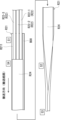
- FIGS. 11 and 12 are diagrams for explaining the method for manufacturing the flavor rod 2A according to embodiment 2, and correspond to Figures 5 and 6. Here, the differences from the method for manufacturing the flavor rod 2 according to embodiment 1 will be mainly described.
- the flavor rod 2A is provided with a partition paper 24. Therefore, in the manufacturing method of the flavor rod 2A, after joining multiple long flavor molding body raw material sheets R22 to the outer wrapping paper raw material sheet R21, a long partition paper raw material sheet R24 is supplied to the conveying path from above the flavor molding body raw material sheet R22 and joined at the second joining section S4.
- the partition paper raw material sheet R24 is a long belt-shaped paper sheet for forming the partition paper 24.
- the symbol B3 shown in FIG. 12 is a bobbin on which the partition paper raw material sheet R24 is wound. The bobbin B3 is freely rotatable and can sequentially pay out the partition paper raw material sheet R24.
- the second joining section S4 is positioned between the joining section S1 and the forming section S2.
- the glue applicator 70 applies the wrapping adhesive glue BD0 and the above-mentioned partition paper adhesive glue BD' in a rail-like (straight line) manner along the longitudinal direction of the upper surface R211 of the outer wrapping paper raw material sheet R21 unwound from the bobbin B1.
- Figure 13 is a diagram illustrating an example of an application pattern of adhesive glue applied to the upper surface R211 of the outer wrapping paper raw material sheet R21 by the glue applicator 70 according to the second embodiment.
- the wrapping adhesive BD0 and the partition paper adhesives BD'1 to BD'3 are arranged at intervals from each other from the first end E1 side of the outer wrapping paper raw material sheet R21.
- the wrapping adhesive BD0 is arranged near the first end E1, similar to the embodiment shown in FIG. 8.
- FIG. 13 shows with dashed lines each of the flavor molded body raw material sheets R22-1 to R22-3 (R22) placed on the outer wrapping paper raw material sheet R21 at the junction S1.
- each of the flavor molded body raw material sheets R22-1 to R22-3 (R22) is arranged between each of the adhesives BD0, BD' applied to the upper surface R211 of the outer wrapping paper raw material sheet R21 by the glue application device 70.
- the long partition paper raw material sheet R24 unwound from the bobbin B3 is supplied onto the outer wrapping paper raw material sheet R21 and the flavor molded body raw material sheet R22 at the second junction S4.
- the width dimension of the partition paper raw material sheet R24 is slightly smaller than the width dimension of the outer wrapping paper raw material sheet R21, and the partition paper raw material sheet R24 is supplied so that the wrapping adhesive glue BD0 is not entirely covered by the partition paper raw material sheet R24.
- the partition paper raw material sheet R24 is supplied onto the outer wrapping paper raw material sheet R21 and the flavor molded body raw material sheet R22, one widthwise end side of the partition paper raw material sheet R24 partially covers only the inner widthwise portion of the wrapping adhesive glue BD0.
- a guide member (not shown) is arranged at the second junction S4 to press the partition paper raw material sheet R24 from above toward the adhesive glues BD0, BD' applied to the outer wrapping paper raw material sheet R21.
- the partition paper raw material sheet R24 is adhered to the outer wrapping paper raw material sheet R21 by being pressed by the guide member.
- Figure 14 is a cross-sectional view showing the state in which the partition paper raw material sheet R24 is adhered to the outer wrapping paper raw material sheet R21. As shown in Figure 14, the partition paper raw material sheet R24 is partially adhered to the upper surface R211 of the outer wrapping paper raw material sheet R21 (ultimately, the inner surface 21A of the outer wrapping paper 21) by the adhesive glues BD0, BD'.
- the symbols R241 to R243 shown in Figure 14 are holding portions that position and hold each flavor molding raw material sheet R22-1 to R22-3 (R22) on the upper surface R211 of the outer wrapping paper raw material sheet R21 (ultimately, the inner surface 21A of the outer wrapping paper 21).
- the holding portions R241 to R243 of the partition paper raw material sheet R24 are formed by non-adhesive areas of the partition paper raw material sheet R24 that are not adhered to each adhesive glue BD0, BD'.
- gaps are formed between the holding portions R241 to R243 and each of the flavor molded body raw material sheets R22-1 to R22-3 (R22), but the holding portions R241 to R243 are at least partially in close contact with each of the flavor molded body raw material sheets R22-1 to R22-3 (R22), and can position and hold each of the flavor molded body raw material sheets R22-1 to R22-3 (R22) by pressing them against the upper surface R211 of the outer wrapping paper raw material sheet R21 (ultimately, the inner surface 21A of the outer wrapping paper 21).
- the outer wrapping paper raw material sheet R21 is rolled up in the direction of arrow C in FIG. 14 using a guide member (not shown).
- a guide member not shown.
- the first end E1 of the outer wrapping paper raw material sheet R21 to which the wrapping adhesive glue BD0 has been applied is overlapped over the second end E2, and the widthwise ends of the outer wrapping paper raw material sheet R21 are bonded together, resulting in a long flavor rod R2 having a cylindrical cross section.
- the long flavor rod R2 is cut to a predetermined length (cutting process). As a result, the flavor rod 2A described in FIG. 10 above is obtained.
- flavor stick 2 flavor rod 3: mouthpiece portion 21: outer wrapping paper 22: flavor molded body 24: partition paper
Landscapes
- Cigarettes, Filters, And Manufacturing Of Filters (AREA)
- Manufacture Of Tobacco Products (AREA)
- Packaging Of Annular Or Rod-Shaped Articles, Wearing Apparel, Cassettes, Or The Like (AREA)
Priority Applications (6)
| Application Number | Priority Date | Filing Date | Title |
|---|---|---|---|
| KR1020257023427A KR20250115454A (ko) | 2023-01-27 | 2023-01-27 | 향미 스틱, 비연소 가열식 향미 흡인 제품, 및 향미 로드를 제조하는 방법 |
| JP2024572809A JPWO2024157478A1 (https=) | 2023-01-27 | 2023-01-27 | |
| EP23918438.5A EP4656067A1 (en) | 2023-01-27 | 2023-01-27 | Flavor stick, heat-not-burn-type flavor inhalation product, and method for producing flavor rod |
| CN202380091818.6A CN120529838A (zh) | 2023-01-27 | 2023-01-27 | 风味棒、加热不燃烧风味吸入产品、以及用于生产风味杆的方法 |
| PCT/JP2023/002721 WO2024157478A1 (ja) | 2023-01-27 | 2023-01-27 | 香味スティック、非燃焼加熱式香味吸引製品、及び香味ロッドの製造方法 |
| TW113102996A TW202430055A (zh) | 2023-01-27 | 2024-01-25 | 香味棒、非燃燒加熱式香味吸嚐製品及香味桿的製造方法 |
Applications Claiming Priority (1)
| Application Number | Priority Date | Filing Date | Title |
|---|---|---|---|
| PCT/JP2023/002721 WO2024157478A1 (ja) | 2023-01-27 | 2023-01-27 | 香味スティック、非燃焼加熱式香味吸引製品、及び香味ロッドの製造方法 |
Publications (1)
| Publication Number | Publication Date |
|---|---|
| WO2024157478A1 true WO2024157478A1 (ja) | 2024-08-02 |
Family
ID=91970127
Family Applications (1)
| Application Number | Title | Priority Date | Filing Date |
|---|---|---|---|
| PCT/JP2023/002721 Ceased WO2024157478A1 (ja) | 2023-01-27 | 2023-01-27 | 香味スティック、非燃焼加熱式香味吸引製品、及び香味ロッドの製造方法 |
Country Status (6)
| Country | Link |
|---|---|
| EP (1) | EP4656067A1 (https=) |
| JP (1) | JPWO2024157478A1 (https=) |
| KR (1) | KR20250115454A (https=) |
| CN (1) | CN120529838A (https=) |
| TW (1) | TW202430055A (https=) |
| WO (1) | WO2024157478A1 (https=) |
Citations (8)
| Publication number | Priority date | Publication date | Assignee | Title |
|---|---|---|---|---|
| JPH07184625A (ja) | 1993-12-27 | 1995-07-25 | Japan Tobacco Inc | 紙巻たばこ製造機の刻たばこ給送装置 |
| JP5220762B2 (ja) | 2006-12-28 | 2013-06-26 | フィリップ・モーリス・プロダクツ・ソシエテ・アノニム | ロッドを通って延びる中空通路を有するタバコロッドを生産するための様々な実施形態 |
| JP2015503335A (ja) | 2011-12-30 | 2015-02-02 | フィリップ・モーリス・プロダクツ・ソシエテ・アノニム | エアロゾル発生装置と共に使用するためのエアロゾル発生物品 |
| JP2019524116A (ja) * | 2016-07-28 | 2019-09-05 | アール・エイ・アイ・ストラテジック・ホールディングス・インコーポレイテッド | 選択器を含むエアロゾル送達装置および関連方法 |
| JP2019187451A (ja) | 2015-03-27 | 2019-10-31 | フィリップ・モーリス・プロダクツ・ソシエテ・アノニム | 電気加熱式エアロゾル発生物品用の紙ラッパー |
| JP2020522998A (ja) * | 2017-06-15 | 2020-08-06 | フィリップ・モーリス・プロダクツ・ソシエテ・アノニム | 誘導加熱可能なエアロゾル形成ロッドを製造するための方法および装置 |
| JP2022507006A (ja) * | 2020-04-17 | 2022-01-18 | 雲南中煙工業有限責任公司 | 植毛技術に基づいて製造される非燃焼式タバコ支柱及び該タバコ支柱の製造方法 |
| KR20220008170A (ko) * | 2020-07-13 | 2022-01-20 | 주식회사 케이티앤지 | 에어로졸 생성 장치 |
Family Cites Families (1)
| Publication number | Priority date | Publication date | Assignee | Title |
|---|---|---|---|---|
| JP4502220B2 (ja) | 2007-02-13 | 2010-07-14 | 大日本スクリーン製造株式会社 | 熱処理装置 |
-
2023
- 2023-01-27 KR KR1020257023427A patent/KR20250115454A/ko active Pending
- 2023-01-27 JP JP2024572809A patent/JPWO2024157478A1/ja active Pending
- 2023-01-27 EP EP23918438.5A patent/EP4656067A1/en active Pending
- 2023-01-27 CN CN202380091818.6A patent/CN120529838A/zh active Pending
- 2023-01-27 WO PCT/JP2023/002721 patent/WO2024157478A1/ja not_active Ceased
-
2024
- 2024-01-25 TW TW113102996A patent/TW202430055A/zh unknown
Patent Citations (8)
| Publication number | Priority date | Publication date | Assignee | Title |
|---|---|---|---|---|
| JPH07184625A (ja) | 1993-12-27 | 1995-07-25 | Japan Tobacco Inc | 紙巻たばこ製造機の刻たばこ給送装置 |
| JP5220762B2 (ja) | 2006-12-28 | 2013-06-26 | フィリップ・モーリス・プロダクツ・ソシエテ・アノニム | ロッドを通って延びる中空通路を有するタバコロッドを生産するための様々な実施形態 |
| JP2015503335A (ja) | 2011-12-30 | 2015-02-02 | フィリップ・モーリス・プロダクツ・ソシエテ・アノニム | エアロゾル発生装置と共に使用するためのエアロゾル発生物品 |
| JP2019187451A (ja) | 2015-03-27 | 2019-10-31 | フィリップ・モーリス・プロダクツ・ソシエテ・アノニム | 電気加熱式エアロゾル発生物品用の紙ラッパー |
| JP2019524116A (ja) * | 2016-07-28 | 2019-09-05 | アール・エイ・アイ・ストラテジック・ホールディングス・インコーポレイテッド | 選択器を含むエアロゾル送達装置および関連方法 |
| JP2020522998A (ja) * | 2017-06-15 | 2020-08-06 | フィリップ・モーリス・プロダクツ・ソシエテ・アノニム | 誘導加熱可能なエアロゾル形成ロッドを製造するための方法および装置 |
| JP2022507006A (ja) * | 2020-04-17 | 2022-01-18 | 雲南中煙工業有限責任公司 | 植毛技術に基づいて製造される非燃焼式タバコ支柱及び該タバコ支柱の製造方法 |
| KR20220008170A (ko) * | 2020-07-13 | 2022-01-20 | 주식회사 케이티앤지 | 에어로졸 생성 장치 |
Non-Patent Citations (1)
| Title |
|---|
| See also references of EP4656067A1 |
Also Published As
| Publication number | Publication date |
|---|---|
| KR20250115454A (ko) | 2025-07-30 |
| CN120529838A (zh) | 2025-08-22 |
| JPWO2024157478A1 (https=) | 2024-08-02 |
| TW202430055A (zh) | 2024-08-01 |
| EP4656067A1 (en) | 2025-12-03 |
Similar Documents
| Publication | Publication Date | Title |
|---|---|---|
| KR102825827B1 (ko) | 향미 흡인기용 카트리지 및 향미 흡인기 | |
| JP2023130469A (ja) | 非燃焼加熱喫煙物品および非燃焼加熱喫煙システム | |
| US20240260643A1 (en) | Flavor stick, non-combustion heating type flavor inhaler product, and production method for flavor stick | |
| JP7369300B2 (ja) | 香味吸引器用のカートリッジ及び香味吸引器 | |
| US20240260644A1 (en) | Flavor stick, heat-not-burn-type flavor inhalation product, and method for producing flavor stick | |
| WO2024157478A1 (ja) | 香味スティック、非燃焼加熱式香味吸引製品、及び香味ロッドの製造方法 | |
| WO2024157477A1 (ja) | 香味スティック、非燃焼加熱式香味吸引製品、及び香味ロッドの製造方法 | |
| WO2024157480A1 (ja) | 香味スティック、非燃焼加熱式香味吸引製品、及び香味ロッドの製造方法 | |
| WO2024157479A1 (ja) | 香味スティック、非燃焼加熱式香味吸引製品、及び香味ロッドの製造方法 | |
| JP7641401B2 (ja) | 香味スティック、非燃焼加熱式香味吸引製品、及び香味スティックの製造方法 | |
| RU2805908C1 (ru) | Картридж для ароматического ингалятора и ароматический ингалятор | |
| JP7855143B2 (ja) | 香味発生物品及び喫煙システム | |
| RU2772361C1 (ru) | Сегмент фильтра, курительное изделие с нагревом без горения и курительная система с нагревом без горения | |
| WO2024127576A1 (ja) | 香味発生物品及び香味吸引システム | |
| WO2024111019A1 (ja) | 香味発生物品及び香味吸引システム | |
| WO2024057517A1 (ja) | 香味発生物品 |
Legal Events
| Date | Code | Title | Description |
|---|---|---|---|
| 121 | Ep: the epo has been informed by wipo that ep was designated in this application |
Ref document number: 23918438 Country of ref document: EP Kind code of ref document: A1 |
|
| ENP | Entry into the national phase |
Ref document number: 1020257023427 Country of ref document: KR Free format text: ST27 STATUS EVENT CODE: A-0-1-A10-A15-NAP-PA0105 (AS PROVIDED BY THE NATIONAL OFFICE) |
|
| WWE | Wipo information: entry into national phase |
Ref document number: 1020257023427 Country of ref document: KR |
|
| ENP | Entry into the national phase |
Ref document number: 2024572809 Country of ref document: JP Kind code of ref document: A |
|
| WWE | Wipo information: entry into national phase |
Ref document number: 2024572809 Country of ref document: JP Ref document number: 202380091818.6 Country of ref document: CN |
|
| WWP | Wipo information: published in national office |
Ref document number: 1020257023427 Country of ref document: KR |
|
| WWP | Wipo information: published in national office |
Ref document number: 202380091818.6 Country of ref document: CN |
|
| NENP | Non-entry into the national phase |
Ref country code: DE |
|
| WWP | Wipo information: published in national office |
Ref document number: 2023918438 Country of ref document: EP |