WO2024157352A1 - 診断装置 - Google Patents
診断装置 Download PDFInfo
- Publication number
- WO2024157352A1 WO2024157352A1 PCT/JP2023/002080 JP2023002080W WO2024157352A1 WO 2024157352 A1 WO2024157352 A1 WO 2024157352A1 JP 2023002080 W JP2023002080 W JP 2023002080W WO 2024157352 A1 WO2024157352 A1 WO 2024157352A1
- Authority
- WO
- WIPO (PCT)
- Prior art keywords
- unit
- diagnosis
- abnormality
- diagnostic
- data
- Prior art date
- Legal status (The legal status is an assumption and is not a legal conclusion. Google has not performed a legal analysis and makes no representation as to the accuracy of the status listed.)
- Ceased
Links
Images




Classifications
-
- G—PHYSICS
- G01—MEASURING; TESTING
- G01M—TESTING STATIC OR DYNAMIC BALANCE OF MACHINES OR STRUCTURES; TESTING OF STRUCTURES OR APPARATUS, NOT OTHERWISE PROVIDED FOR
- G01M99/00—Subject matter not provided for in other groups of this subclass
- G01M99/005—Testing of complete machines, e.g. washing-machines or mobile phones
-
- G—PHYSICS
- G01—MEASURING; TESTING
- G01M—TESTING STATIC OR DYNAMIC BALANCE OF MACHINES OR STRUCTURES; TESTING OF STRUCTURES OR APPARATUS, NOT OTHERWISE PROVIDED FOR
- G01M99/00—Subject matter not provided for in other groups of this subclass
- G01M99/008—Subject matter not provided for in other groups of this subclass by doing functionality tests
Definitions
- This disclosure relates to a diagnostic device that diagnoses abnormalities.
- Patent Document 1 There is a known technology that diagnoses signs of abnormalities occurring in industrial machinery by collecting and analyzing a large amount of physical quantity data such as current and vibration (for example, Patent Document 1).
- the diagnostic device disclosed herein includes a first acquisition unit that acquires first status data indicating the status of the diagnostic target, a continuous diagnosis unit that diagnoses an abnormality in the diagnostic target based on the first status data acquired by the first acquisition unit, a second acquisition unit that acquires second status data different from the first status data based on the diagnosis result by the continuous diagnosis unit, and an emergency diagnosis unit that diagnoses the cause of the abnormality that has occurred in the diagnostic target based on the second status data acquired by the second acquisition unit.
- FIG. 1 illustrates an example of a system including a diagnostic device.
- 1 is a block diagram showing an example of a hardware configuration of an industrial machine
- FIG. 2 is a block diagram showing an example of a hardware configuration of a diagnostic device.
- FIG. 2 is a block diagram showing an example of the functions of the diagnostic device.
- FIG. 11 is a diagram showing an example of a diagnosis result. 13 is an example of a display screen that displays information generated by a trigger generating unit. 13 is an example of a reception screen.
- FIG. 2 is a block diagram showing an example of the functions of the diagnostic device.
- FIG. 1 is a diagram for explaining clustering.
- based on XX means “based on at least XX,” and includes cases where it is based on other elements in addition to XX. Furthermore, “based on XX” is not limited to cases where XX is used directly, but also includes cases where it is based on XX that has been calculated or processed. "XX” is any element (for example, any information).
- First Embodiment 1 is a diagram showing an example of a system including a diagnostic device.
- the system includes, for example, an industrial machine 1 and a diagnostic device 10.
- the industrial machine 1 is a machine that operates at an industrial site.
- the industrial machine 1 is, for example, a machine tool, an injection molding machine, a laser processing machine, a three-dimensional printer, or a robot.
- the industrial machine 1 is controlled by a control device 2.
- the diagnostic device 10 is a device that diagnoses abnormalities in the industrial machine 1.
- the diagnostic device 10 is connected to the control device 2 via a wired or wireless connection.
- the diagnostic device 10 may be implemented in the control device 2.
- FIG. 2 is a block diagram showing an example of the hardware configuration of the industrial machine 1.
- the industrial machine 1 includes a control device 2, an input/output device 3, a servo amplifier 4, a servo motor 5, a spindle amplifier 6, a spindle motor 7, an auxiliary device 8, and a sensor 9.
- the control device 2 is, for example, a numerical control device that controls the industrial machine 1.
- the control device 2 includes, for example, a hardware processor 201, a bus 202, a ROM (Read Only Memory) 203, a RAM (Random Access Memory) 204, and a non-volatile memory 205.
- the hardware processor 201 is a processor that controls the entire control device 2 in accordance with a system program.
- the hardware processor 201 reads out the system program stored in the ROM 203 via the bus 202.
- the hardware processor 201 is, for example, a CPU (Central Processing Unit) or an electronic circuit.
- the bus 202 is a communication path that connects each piece of hardware in the control device 2 to each other. Each piece of hardware in the control device 2 exchanges data via the bus 202.
- ROM 203 is a storage device that stores system programs and the like. ROM 203 is a computer-readable storage medium.
- RAM 204 is a storage device that temporarily stores various data. RAM 204 functions as a working area for the hardware processor 201 to process various data.
- the non-volatile memory 205 is a storage device that retains data even when the control device 2 is powered off.
- the non-volatile memory 205 stores, for example, the operating program of the industrial machine 1.
- the non-volatile memory 205 is a computer-readable storage medium.
- the non-volatile memory 205 is, for example, a battery-backed memory or an SSD (Solid State Drive).
- the control device 2 further includes a first interface 206, an axis control circuit 207, a spindle control circuit 208, a PLC (Programmable Logic Controller) 209, an I/O unit 210, a second interface 211, and a third interface 212.
- a PLC Programmable Logic Controller
- the first interface 206 connects the bus 202 and the input/output device 3.
- the first interface 206 sends, for example, various data processed by the hardware processor 201 to the input/output device 3.
- the input/output device 3 receives various data via the first interface 206 and displays the various data on a display.
- the input/output device 3 also receives input of various data and sends the various data via the first interface 206 to, for example, the hardware processor 201.
- the input/output device 3 is, for example, a touch panel.
- the input/output device 3 is, for example, a capacitive touch panel.
- the touch panel is not limited to a capacitive touch panel, and may be a touch panel of another type.
- the input/output device 3 is installed in an operation panel (not shown) in which the control device 2 is stored.
- the axis control circuit 207 is a circuit for controlling the servo motor 5.
- the axis control circuit 207 receives control commands from the hardware processor 201 and sends various commands to the servo amplifier 4 for driving the servo motor 5.
- the axis control circuit 207 sends, for example, a torque command for controlling the torque of the servo motor 5 to the servo amplifier 4.
- the servo amplifier 4 receives commands from the axis control circuit 207 and supplies current to the servo motor 5.
- the servo motors 5 are driven by receiving a current supply from the servo amplifier 4.
- the servo motors 5 are provided for each control axis of the industrial machine 1. If the industrial machine 1 is a machine tool having five axes, the servo motors 5 include, for example, an X-axis servo motor, a Y-axis servo motor, a Z-axis servo motor, an A-axis servo motor, and a C-axis servo motor.
- the axis control circuit 207 and the servo amplifier 4 are provided for each servo motor 5.
- the servo motor 5 is connected to, for example, a ball screw that drives the tool post.
- the structure of the industrial machine 1, such as the tool post moves along a specified control axis.
- the servo motor 5 has a built-in encoder (not shown) that detects the position and feed speed of the control axis. Position feedback information and speed feedback information indicating the position of the control axis and the feed speed of the control axis detected by the encoder, respectively, are fed back to the axis control circuit 207. In this way, the axis control circuit 207 performs feedback control of each control axis.
- the spindle control circuit 208 is a circuit for controlling the spindle motor 7.
- the spindle control circuit 208 receives a control command from the hardware processor 201 and sends a command to the spindle amplifier 6 to drive the spindle motor 7.
- the spindle control circuit 208 sends, for example, a spindle speed command to the spindle amplifier 6 to control the rotation speed of the spindle motor 7.
- the spindle amplifier 6 receives commands from the spindle control circuit 208 and supplies current to the spindle motor 7.
- the spindle motor 7 is driven by a current supplied from the spindle amplifier 6.
- the spindle motor 7 is connected to the main shaft and rotates the main shaft.
- the PLC 209 is a device that executes a ladder program to control the auxiliary device 8.
- the PLC 209 sends commands to the auxiliary device 8 via the I/O unit 210.
- the I/O unit 210 is an interface that connects the PLC 209 and the auxiliary device 8.
- the I/O unit 210 sends commands received from the PLC 209 to the auxiliary device 8.
- the auxiliary device 8 is installed in the industrial machine 1 and performs auxiliary operations in the industrial machine 1.
- the auxiliary device 8 operates based on commands received from the I/O unit 210.
- the auxiliary device 8 may be a device installed in the periphery of the industrial machine 1.
- the auxiliary device 8 is, for example, a tool changer, a cutting fluid injection device, or an opening/closing door drive device.
- the second interface 211 connects the bus 202 and the sensor 9.
- the second interface 211 sends, for example, information acquired by the sensor 9 to the hardware processor 201 via the bus 202.
- Sensors 9 are installed in various parts of the industrial machine 1 to detect various physical quantities. Examples of sensors 9 include a temperature sensor, an acceleration sensor, an ammeter, and a liquid level meter.
- the third interface 212 connects the bus 202 and the diagnostic device 10.
- the third interface 212 sends, for example, information processed by the hardware processor 201 to the diagnostic device 10 via the bus 202.
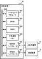
- FIG. 3 is a block diagram showing an example of the hardware configuration of the diagnostic device 10.
- the diagnostic device 10 includes, for example, a hardware processor 101, a bus 102, a ROM 103, a RAM 104, a non-volatile memory 105, a first interface 106, and a second interface 107.
- the hardware processor 101 is a processor that controls the entire diagnostic device 10 in accordance with a system program.
- the hardware processor 101 reads the system program stored in the ROM 103 via the bus 102.
- the hardware processor 101 is, for example, a CPU or an electronic circuit.
- the bus 102 is a communication path that connects each piece of hardware in the diagnostic device 10 to each other. Each piece of hardware in the diagnostic device 10 exchanges data via the bus 102.
- ROM 103 is a storage device that stores system programs and the like. ROM 103 is a computer-readable storage medium.
- RAM 104 is a storage device that temporarily stores various data. RAM 104 functions as a working area for the hardware processor 101 to process various data.
- the non-volatile memory 105 is a storage device that retains data even when the power to the diagnostic device 10 is turned off.
- the non-volatile memory 105 is a computer-readable storage medium.
- the non-volatile memory 105 is composed of, for example, a battery-backed memory or an SSD.
- the first interface 106 connects the bus 102 and the input/output device 11.
- the first interface 106 sends, for example, various data processed by the hardware processor 101 to the input/output device 11.
- the input/output device 11 receives various data via the first interface 106 and displays the various data on a display.
- the input/output device 11 also receives input of various data and sends the various data to, for example, the hardware processor 101 via the first interface 106.
- the input/output device 11 is, for example, a touch panel.
- the second interface 107 connects the bus 102 and the control device 2.
- the second interface 107 for example, receives various data from the control device 2 and sends it to the hardware processor 101.
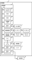
- FIG. 4 is a block diagram showing an example of the functions of the diagnostic device 10.
- the diagnostic device 10 includes, for example, a first acquisition unit 111, a first data storage unit 112, a continuous diagnosis unit 113, a first history storage unit 114, a trigger generation unit 115, a result output unit 116, a reception unit 117, a second acquisition unit 118, a second data storage unit 119, an emergency diagnosis unit 120, and a second history storage unit 121.
- the first acquisition unit 111, the constant diagnosis unit 113, the trigger generation unit 115, the result output unit 116, the reception unit 117, the second acquisition unit 118, and the emergency diagnosis unit 120 are realized, for example, by the hardware processor 101 performing calculations using the system program stored in the ROM 103 and various data stored in the non-volatile memory 105.
- the first data storage unit 112, the first history storage unit 114, the second data storage unit 119, and the second history storage unit 121 are realized, for example, by storing various information in the RAM 104 or the non-volatile memory 105.
- the first acquisition unit 111 acquires first status data indicating the status of the diagnosis target.
- the diagnosis target is, for example, the devices and parts that constitute the industrial machine 1.
- the devices and parts that constitute the industrial machine 1 are, for example, bearings, servo motors 5, spindle motors 7, linear guides, tools, and spindles.
- the diagnosis target may also be a compressor, motor, etc. of equipment installed in a factory.
- the first acquisition unit 111 acquires the first status data at a predetermined cycle while the diagnosis target is in operation.
- the period during which the diagnosis target is in operation is, for example, a period during which the industrial machine 1 is operating based on an operation program.
- the specified period is, for example, the control period of the diagnostic device 10.
- the first acquisition unit 111 may change the period for acquiring the first status data.
- the first acquisition unit 111 may acquire the first status data based on information specifying the period accepted by the acceptance unit 117, which will be described later.
- the first acquisition unit 111 may acquire the first status data at a period specified by the operator.
- the first state data is, for example, data indicating a torque command, as well as a current value, vibration, temperature, sound, elastic wave, speed, and rotation speed.
- the data includes signals.
- the first acquisition unit 111 acquires, for example, a torque command that specifies the torque of the spindle motor 7.
- the first acquisition unit 111 acquires the first status data from the sensor 9 installed in the diagnosis target or from the control device 2.
- the first data storage unit 112 stores the first status data acquired by the first acquisition unit 111.
- the first data storage unit 112 stores the first status data in association with time information indicating the time when the first status data was acquired.
- the first status data stored in the first data storage unit 112 is time-series data.
- the data stored in the first data storage unit 112 is time-series data of a value specifying the torque of the spindle motor 7.
- the continuous diagnosis unit 113 diagnoses an abnormality in the diagnosis target based on the first status data stored in the first data storage unit 112. In other words, the continuous diagnosis unit 113 diagnoses an abnormality in the diagnosis target based on the first status data acquired by the first acquisition unit 111.
- the continuous diagnosis unit 113 diagnoses whether an abnormality has occurred in the diagnosis target.
- the continuous diagnosis unit 113 diagnoses the abnormality of the diagnosis target using a predetermined abnormality detection model.
- the anomaly detection model is, for example, a model that diagnoses that an abnormality has occurred in the diagnosis target when the value of the first state data exceeds a preset threshold. There may be multiple thresholds set in the anomaly detection model.
- the anomaly detection model may be set with a first threshold, a second threshold greater than the first threshold, and a third threshold greater than the second threshold. In this case, the anomaly detection model calculates the degree of anomaly.
- the degree of abnormality is "0.” In this case, no abnormality has occurred in the object to be diagnosed. If the value of the first status data is greater than the first threshold and equal to or less than the second threshold, the degree of abnormality is "1.” In this case, an abnormality of low importance has occurred in the object to be diagnosed.
- the degree of abnormality is "2." In this case, an abnormality of medium importance has occurred in the object to be diagnosed. If the value of the first status data exceeds the third threshold value, the degree of abnormality is "3.” In this case, an abnormality of high importance has occurred in the object to be diagnosed.
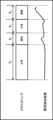
- FIG. 5 is a diagram showing an example of a diagnosis result by the continuous diagnosis unit 113.
- the value of the first status data is equal to or less than the first threshold value. Therefore, the continuous diagnosis unit 113 determines that the diagnosis target is operating normally.
- the value of the first status data exceeds the first threshold value and is equal to or less than the second threshold value. In this case, the continuous diagnosis unit 113 determines that an abnormality with an abnormality level of "1" has occurred in the object to be diagnosed. Further, in period T4, the value of the first status data exceeds the second threshold value. In this case, the continuous diagnosis unit 113 determines that an abnormality with an abnormality level of "2" has occurred in the object to be diagnosed.
- the continuous diagnosis unit 113 may diagnose an abnormality in the diagnosis target using an anomaly detection model selected from a plurality of anomaly detection models that calculate the degree of anomaly.
- the anomaly detection model is an anomaly detection model among the plurality of anomaly detection models that most appropriately calculates the degree of anomaly occurring in the diagnosis target.
- the difference between the degree of abnormality in normal times and the degree of abnormality in abnormal times calculated by the anomaly detection model used by the continuous diagnosis unit 113 is greater than the difference between the degree of abnormality in normal times and the degree of abnormality in abnormal times calculated by other anomaly detection models among the multiple anomaly detection models.
- the anomaly detection model is selected from a number of anomaly detection models depending on the components constituting the diagnosis target, the structure of the industrial machine 1 in which the diagnosis target is installed, the setting state of the industrial machine 1, the operating program that operates the industrial machine 1, and the environment in which the diagnosis target is installed.
- the setting state of the industrial machine 1 is, for example, the preload of the bearings.
- the setting state of the industrial machine 1 also includes the setting state of the parameters set in the control device 2.
- the environment in which the diagnosis target is installed is, for example, the temperature in the factory in which the industrial machine 1 is installed. Now, we return to the explanation of FIG. 4.
- the first history storage unit 114 stores the diagnosis results by the continuous diagnosis unit 113.
- the diagnosis results are, for example, information indicating whether or not an abnormality has occurred in the diagnosis target.
- the diagnosis results may include information indicating the degree of abnormality.
- the diagnosis results may include information indicating the time when the abnormality occurred.
- the trigger generation unit 115 generates a trigger based on the diagnosis result stored in the first history storage unit 114.
- the trigger generation unit 115 generates a trigger in response to the first history storage unit 114 storing a diagnosis result indicating that an abnormality has occurred in the diagnosis target.
- the trigger is information or a signal that causes the second acquisition unit 118 to acquire second status data that is different from the first status data.
- the information generated by the trigger generation unit 115 is, for example, information for prompting the operator to perform a diagnostic operation.
- the information prompting the operator to perform a diagnostic operation is, for example, displayed on a display device.
- FIG. 6 is an example of a display screen that displays information generated by the trigger generation unit 115.
- the display screen displays a character string saying, "An abnormality has occurred. Please perform a diagnostic operation.”
- an "OK" button is displayed below this character string.
- the operator executes a diagnostic operation. For example, if the first status data is a torque command for the spindle motor 7 and the constant diagnosis unit 113 diagnoses that an abnormality has occurred in the diagnostic target, the operator executes a diagnostic operation for the spindle.
- the diagnostic operation is, for example, measuring the runout of the spindle.
- the runout of the spindle is measured, for example, by measuring the distance between a tool holder attached to the spindle and an eddy current displacement sensor while rotating the spindle.
- the runout of the spindle may also be measured by placing a dial gauge against the tool holder attached to the spindle.
- the diagnostic operation may be measuring vibrations of the diagnostic object.
- the vibrations of the diagnostic object may be, for example, vibrations that occur when the diagnostic object is subjected to a frequency sweep operation, and vibrations that occur when the diagnostic object is excited.
- the second state data may be vibration data acquired when the diagnostic object is subjected to a frequency sweep operation, or vibration data acquired when the diagnostic object is excited.
- the frequency sweep operation refers to vibrating a motor such as the servo motor 5 or spindle motor 7 using an input signal input to the motor.
- the frequency sweep operation refers, for example, to gradually increasing the frequency of the input signal to the motor.
- the object to be diagnosed is vibrated, for example, when an impact is applied to the object to be diagnosed using an impulse hammer or the like.
- the result output unit 116 outputs the diagnosis result by the continuous diagnosis unit 113.
- the result output unit 116 causes the diagnosis result indicating that the diagnosis target is operating normally to be displayed, for example, on a display device.
- the result output unit 116 displays the diagnosis result indicating that an abnormality has occurred in the diagnosis target, for example, on a display device.
- the display device is, for example, the input/output device 11.
- the result output unit 116 may output an electronic file in which the diagnosis result is recorded, for example, to an external server (not shown).
- the reception unit 117 receives input of the results of the diagnostic operation by the operator. For example, the reception unit 117 displays a reception screen on a display device and receives input of the results of the diagnostic operation from the reception screen.
- FIG. 7 is an example of a reception screen.
- the reception screen includes, for example, an area for receiving input of the measured value of the runout of the spindle, and an area for receiving input of the measured value of the vibration of the spindle.
- the reception unit 117 receives the input of the results of the diagnostic operation.
- the second acquisition unit 118 acquires second status data different from the first status data based on the diagnosis result by the continuous diagnosis unit 113.
- the second status data is, for example, information indicating the result of a diagnostic operation by an operator accepted by the acceptance unit 117.
- the second acquisition unit 118 acquires information indicating the result of the diagnostic operation performed based on the trigger.
- the second acquisition unit 118 acquires, for example, information indicating the runout of the spindle and information indicating the vibration of the spindle.
- the second status data is not limited to information accepted by the acceptance unit 117.
- the second status data may be data detected by the sensor 9. In this case, the second acquisition unit 118 starts acquiring the second status data at a predetermined cycle in response to the generation of a trigger by the trigger generation unit 115.
- the data detected by the sensor 9 is, for example, data indicating a torque command, a current value, a vibration, a temperature, a sound, an elastic wave, a speed, and a rotation speed.
- the data includes a signal.
- the second state data may be data obtained from the control device 2.
- the second acquisition unit 118 may, for example, acquire information indicating the electrical resistance between the workpiece and the tool during cutting from the sensor 9. It is known that the electrical resistance between the tool and the workpiece decreases as the tool wear progresses. Therefore, by the second acquisition unit 118 acquiring information indicating the electrical resistance between the tool and the workpiece, the emergency diagnosis unit 120, which will be described later, can diagnose the wear of the tool based on the information indicating this electrical resistance.
- the second acquisition unit 118 may also acquire, for example, the temperature of the bearing from the sensor 9. It is known that the temperature of the bearing rises when the bearing is damaged. Therefore, by the second acquisition unit 118 acquiring the temperature of the bearing, the emergency diagnosis unit 120, which will be described later, can diagnose damage to the bearing based on this temperature.
- the second data storage unit 119 stores the second status data acquired by the second acquisition unit 118. In other words, the second data storage unit 119 stores the information accepted by the acceptance unit 117.
- the second data storage unit 119 also stores data detected by the sensor 9.
- the second data storage unit 119 stores the second status data in association with time information indicating the time when the second status data was acquired.
- the second status data stored in the second data storage unit 119 may be time-series data.
- the emergency diagnosis unit 120 diagnoses the cause of the abnormality that has occurred in the diagnosis target based on the second status data acquired by the second acquisition unit 118. In other words, the emergency diagnosis unit 120 diagnoses the cause of the abnormality that has occurred in the diagnosis target based on the second status data stored in the second data storage unit 119.
- the emergency diagnosis unit 120 uses a predetermined diagnosis model to diagnose the cause of an abnormality that has occurred in the diagnosis target.
- the cause of the abnormality is, for example, the location where the abnormality occurred and the state of the abnormality.
- the emergency diagnosis unit 120 diagnoses that an abnormality has occurred in a bearing, a motor, or a tool as the cause of the abnormality.
- the emergency diagnosis unit 120 also diagnoses that wear, loss, or breakage has occurred, for example.
- the emergency diagnosis unit 120 also diagnoses that a part has reached the end of its life.
- the diagnostic model is, for example, a model that indicates the correlation between the second status data and the cause of an abnormality that has occurred in the diagnostic target.
- the diagnostic model is generated by performing machine learning using the second status data and information indicating the cause of the abnormality as training data.
- the diagnostic model outputs information indicating that damage has occurred to the spindle bearings, for example, when the measured value of the spindle runout is equal to or greater than ⁇ 1 [mm] and less than ⁇ 2 [mm], and vibrations in a specific frequency band appear with the rotation of the spindle.
- the emergency diagnosis unit 120 diagnoses that damage has occurred to the spindle bearings.
- the vibrations in the specific frequency band are, for example, vibrations that include sideband waves of a wave that indicates the rotation frequency of the spindle.
- the diagnostic model outputs information indicating that a foreign object has become caught between the spindle and the tool holder, for example, when the measured value of the spindle runout is equal to or greater than ⁇ 2 [mm] and vibrations in a specific frequency band appear as the spindle rotates.
- the emergency diagnosis unit 120 diagnoses that a foreign object has become caught between the spindle and the tool holder.
- the vibrations in the specific frequency band are, for example, vibrations that indicate the rotational frequency of the spindle.
- the emergency diagnosis unit 120 may diagnose the cause of the abnormality that has occurred in the diagnosis target based on the correlation between the multiple types of data. For example, if there is a correlation between the rotation speed of the servo motor 5 under normal conditions and the frequency component of the vibration of the servo motor 5 under normal conditions, the correlation between the rotation speed of the servo motor 5 and the frequency component of the vibration under abnormal conditions is different from the correlation under normal conditions. Therefore, the emergency diagnosis unit 120 diagnoses the cause of the abnormality in the diagnosis target based on the fact that the correlation between the rotation speed of the servo motor 5 and the frequency component of the vibration is different from the correlation between the rotation speed of the servo motor 5 and the frequency component of the vibration under normal conditions.
- the second history storage unit 121 stores a history of cause information indicating the cause of an abnormality in the diagnosis target diagnosed by the emergency diagnosis unit 120.
- the cause information is stored in association with the second status data and the acquisition time of the second status data.
- the emergency diagnosis unit 120 may diagnose the cause of an abnormality that has occurred in the diagnosis target based on the cause information recorded in the second history storage unit 121. That is, the emergency diagnosis unit 120 determines whether the past second state data stored in the second history storage unit 121 matches the second state data stored in the second data storage unit 119. If they match, the emergency diagnosis unit 120 diagnoses that an abnormality indicated by the cause information stored in association with the second state data in the second history storage unit 121 has occurred in the diagnosis target.
- the emergency diagnosis unit 120 may diagnose that an abnormality indicated by the cause information stored in association with the second status data has occurred in the diagnosis target.
- the result output unit 116 outputs the diagnosis result by the emergency diagnosis unit 120.
- the result output unit 116 displays the diagnosis result, for example, on a display device.
- FIG. 8 is a diagram showing an example of a diagnosis result displayed on the display device.
- the result output unit 116 displays the character string "High possibility of spindle bearing abnormality" indicating the diagnosis result on the display screen.
- the result output unit 116 may display the diagnosis result by the emergency diagnosis unit 120 together with the diagnosis result by the constant diagnosis unit 113 on the display device.
- the result output unit 116 may output an electronic file in which the diagnosis result is recorded to, for example, an external server (not shown).
- FIG. 9 is a flowchart showing an example of the flow of processing executed by the diagnostic device 10.
- the first acquisition unit 111 acquires the first state data (step SA1).
- the first data storage unit 112 stores the first state data acquired by the first acquisition unit 111 (step SA2).
- the continuous diagnosis unit 113 diagnoses an abnormality in the diagnosis target based on the first status data stored in the first data storage unit 112 (step SA3).
- step SA4 If no abnormality has occurred in the diagnosis target (No in step SA4), the first acquisition unit 111 continues acquiring the first status data (step SA1).
- the first history storage unit 114 stores the diagnosis result by the continuous diagnosis unit 113 (step SA5).
- the trigger generation unit 115 When the diagnosis result is stored in the first history storage unit 114, the trigger generation unit 115 generates a trigger and the result output unit 116 outputs the diagnosis result (step SA6).
- step SA7 When the trigger generation unit 115 generates a trigger, a diagnostic operation is performed by an operator, and the reception unit 117 receives input of the results of the diagnostic operation (step SA7).
- the second acquisition unit 118 acquires the second status data (step SA8).
- the second status data is information indicating the result of the diagnostic operation accepted by the acceptance unit 117.
- the second data storage unit 119 stores the second status data acquired by the second acquisition unit 118 (step SA9).
- the emergency diagnosis unit 120 diagnoses the cause of the abnormality that has occurred in the diagnosis target based on the second status data stored in the second data storage unit 119 (step SA10).
- the second history storage unit 121 stores information indicating the cause of the abnormality diagnosed by the emergency diagnosis unit 120 (step SA11).
- the result output unit 116 outputs information indicating the cause of the abnormality stored in the second history storage unit 121 (step SA12), and the process ends.
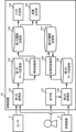
- Second Embodiment 10 is a block diagram showing an example of functions of the diagnostic device 10 of the second embodiment.
- functions different from those of the first embodiment will be mainly described, and descriptions of functions that are the same as those of the first embodiment may be omitted.
- the diagnostic device 10 of this embodiment differs from the diagnostic device 10 of the first embodiment mainly in that the continuous diagnostic unit 113 includes a first diagnostic unit 113A and a second diagnostic unit 113B.
- the continuous diagnosis unit 113 includes a first diagnosis unit 113A and a second diagnosis unit 113B.
- the first diagnosis unit 113A diagnoses whether or not an abnormality has occurred in the diagnosis target based on the first state data.
- the first diagnosis unit 113A diagnoses whether or not an abnormality has occurred in the diagnosis target using a predetermined abnormality detection model.
- the anomaly detection model is, for example, a model that diagnoses that an anomaly has occurred when the value of the first state data exceeds a preset threshold value.
- the second diagnosis unit 113B diagnoses the type of abnormality that has occurred in the diagnosis target based on the first status data.
- the second diagnosis unit 113B diagnoses the type of abnormality by clustering the first status data.
- FIG. 11 is a diagram for explaining clustering.
- Each black circle shown in FIG. 11 is analysis data obtained by analyzing the first state data.
- the analysis data is, for example, multidimensional data obtained by frequency analysis of the first state data.
- the second diagnostic unit 113B groups the analysis data using a clustering method such as the k-means method. For example, the second diagnostic unit 113B groups the analysis data into a first group G1, a second group G2, and a third group G3.
- Each group is labeled with information indicating an anomaly. For example, if analysis data of the first status data acquired when a known anomaly occurred is included in a certain group, the group is presumed to be a collection of analysis data of the first status data acquired when the known anomaly occurred. In other words, the group is labeled with information indicating the known anomaly.
- the analytical data D1 is data obtained by analyzing the first status data acquired when the diagnostic target is operating normally.
- the other analytical data included in the first group is data obtained by analyzing the first status data acquired when the diagnostic target is operating normally. Therefore, the first group is labeled with information indicating that the diagnostic target is normal.
- analytical data D2 is data obtained by analyzing the first condition data acquired when the diagnostic object is operating in a worn state.
- the other analytical data included in the second group is data obtained by analyzing the first condition data acquired when the diagnostic object is operating in a worn state. Therefore, the second group is labeled with information indicating that the diagnostic object is worn.
- analytical data D3 is data obtained by analyzing the first state data acquired when the diagnostic object is operating in a damaged state.
- the other analytical data included in the third group is data obtained by analyzing the first state data acquired when the diagnostic object is operating in a damaged state. Therefore, the third group is labeled with information indicating that the diagnostic object is damaged.
- the second diagnostic unit 113B determines to which group the analysis data obtained by analyzing the first status data belongs. For example, if the analysis data belongs to the first group G1, the second diagnostic unit 113B diagnoses that the diagnostic target is operating normally.
- the second diagnostic unit 113B diagnoses that the diagnostic object is operating in a worn-out state. In other words, the second diagnostic unit 113B diagnoses that the type of abnormality that has occurred in the diagnostic object is wear.
- the second diagnostic unit 113B diagnoses that the diagnostic object is operating in a damaged state. In other words, the second diagnostic unit 113B diagnoses that the type of abnormality that has occurred in the diagnostic object is damage.
- the second diagnosis unit 113B diagnoses that an unknown abnormality has occurred in the diagnosis target.
- FIG. 12 is a diagram showing an example of a diagnosis result by the continuous diagnosis unit 113.
- the first diagnosis unit 113A determines that the diagnosis target is operating normally when the value of the first status data is equal to or less than a predetermined threshold value. Furthermore, the first diagnosis unit 113A diagnoses that an abnormality has occurred in the diagnosis target when the value of the first status data exceeds the predetermined threshold value. In other words, the first diagnosis unit 113A diagnoses that an abnormality has occurred in the diagnosis target in periods T2 and T4.
- the second diagnostic unit 113B diagnoses the type of abnormality that has occurred in the diagnostic object based on the analysis data obtained by analyzing the first condition data. For example, the second diagnostic unit 113B diagnoses that the diagnostic object is worn out in the period T2. The second diagnostic unit 113B also diagnoses that the diagnostic object is damaged in the period T4.
- the first history storage unit 114 stores the diagnosis results by the continuous diagnosis unit 113.
- the trigger generation unit 115 generates a trigger based on the diagnosis results stored in the first history storage unit 114.
- the trigger generation unit 115 generates a trigger in response to the first history storage unit 114 storing a diagnosis result indicating that an abnormality has occurred in the diagnosis target.
- FIG. 13 is an example of a display screen that displays information generated by the trigger generation unit 115.
- the display screen displays a character string stating, "An unknown abnormality has occurred. Please perform a diagnostic operation.”
- an "OK" button is displayed below this character string.
- the operator When the information generated by the trigger generation unit 115 is displayed on the display screen, the operator performs a diagnostic operation.
- the result output unit 116 outputs the diagnosis result by the continuous diagnosis unit 113. Note that the functions of the reception unit 117, the second acquisition unit 118, the second data storage unit 119, the emergency diagnosis unit 120, and the second history storage unit 121 are the same as those in the first embodiment.
- the reception unit 117 may receive information specifying the type of first status data.
- the operator can specify the type of first status data to be used for diagnosis in the continuous diagnosis unit 113.
- the reception unit 117 may also receive information specifying an anomaly detection model.
- multiple anomaly detection models may be stored in a storage unit (not shown) in advance.
- the first diagnosis unit 113A may diagnose an anomaly in the diagnosis target using the specified anomaly detection model.
- the second acquisition unit 118 may acquire the diagnosis result by the continuous diagnosis unit 113. That is, the second acquisition unit 118 may acquire the diagnosis result stored in the first history storage unit 114. In this case, the emergency diagnosis unit 120 diagnoses the cause of the abnormality that has occurred in the diagnosis target based on the diagnosis result by the continuous diagnosis unit 113 and the second status data.
- the second acquisition unit 118 may determine the type of second condition data to acquire depending on the diagnosis result by the continuous diagnosis unit 113. For example, the second acquisition unit 118 may acquire either information indicating spindle runout or information indicating spindle vibration depending on whether the diagnosis result is wear or damage.
- the diagnostic device 10 includes a first acquisition unit 111 that acquires first status data indicating the status of the diagnostic object, a continuous diagnosis unit 113 that diagnoses an abnormality in the diagnostic object based on the first status data acquired by the first acquisition unit 111, a second acquisition unit 118 that acquires second status data different from the first status data based on the diagnosis result by the continuous diagnosis unit 113, and an emergency diagnosis unit 120 that diagnoses the cause of an abnormality that has occurred in the diagnostic object based on the second status data acquired by the second acquisition unit 118.
- the diagnostic device 10 can diagnose the diagnosis target based on the first status data that can be acquired at any time while the diagnosis target is operating. In other words, when diagnosing the diagnosis target, the diagnostic device 10 does not affect the operation of the diagnosis target.
- the second acquisition unit 118 acquires the second status data only when the continuous diagnosis unit 113 determines that it is necessary. In other words, the second acquisition unit 118 acquires the second status data at an appropriate timing. Therefore, the diagnosis device 10 can reduce costs associated with abnormality diagnosis.
- the diagnostic device 10 diagnoses the diagnostic target based on the second state data, not just the first state data. Therefore, the diagnostic device 10 can ensure the reliability of the diagnostic results.
- the continuous diagnosis unit 113 also diagnoses the abnormality of the diagnosis target using an anomaly detection model selected from a plurality of anomaly detection models that calculate the degree of anomaly, and the difference between the degree of anomaly in normal times and the degree of anomaly in abnormal times calculated by the anomaly detection model is greater than the difference between the degree of anomaly in normal times and the degree of anomaly in abnormal times calculated by each of the other anomaly detection models among the plurality of anomaly detection models. Therefore, the continuous diagnosis unit 113 can appropriately diagnose the abnormality of the diagnosis target.
- the anomaly detection model is selected from a number of anomaly detection models depending on the components constituting the diagnosis target, the structure of the industrial machine 1 in which the diagnosis target is installed, the setting state of the industrial machine 1, the operating program that operates the industrial machine 1, and the environment in which the diagnosis target is installed.
- the anomaly detection model is the optimal model for detecting anomalies. This allows the continuous diagnosis unit 113 to appropriately diagnose anomalies in the diagnosis target.
- the diagnostic device 10 further includes a reception unit 117 that receives at least one of information specifying the type of first state data and information specifying the type of anomaly detection model. Therefore, the diagnostic device 10 can appropriately diagnose the cause of an anomaly that has occurred in the diagnostic target based on the first state data and the anomaly detection model that are suitable for the diagnostic target.
- the first acquisition unit 111 also changes the cycle for acquiring the first status data. Therefore, the operator can set the cycle to match the processing capacity of the diagnostic device 10.
- the second state data is vibration data acquired when the diagnosis target is subjected to a frequency sweep operation, or vibration data acquired when the diagnosis target is vibrated. Therefore, the diagnosis device 10 can diagnose the cause of an abnormality that has occurred in the diagnosis target based on the vibration data.
- the emergency diagnosis unit 120 also diagnoses the cause of the abnormality by analyzing the frequency components of the second state data. Therefore, the abnormality diagnosis unit can accurately diagnose the cause of the abnormality that has occurred in the diagnosis target.
- the second status data also includes multiple types of data, and the emergency diagnosis unit 120 diagnoses the cause of the abnormality that has occurred in the diagnosis target based on the correlation between the multiple types of data. Therefore, the emergency diagnosis unit 120 can accurately diagnose the cause of the abnormality that has occurred in the diagnosis target.
- the diagnostic device 10 further includes a history storage unit that records a history of cause information indicating the cause of the abnormality diagnosed by the emergency diagnosis unit 120, and the emergency diagnosis unit 120 diagnoses the cause based on the cause information recorded in the history storage unit. Therefore, the emergency diagnosis unit 120 diagnoses the cause of the abnormality that has occurred in the diagnosis target based on the history of past abnormalities. As a result, the diagnostic device 10 can reduce the processing load related to the diagnosis of the abnormality.
- the history storage unit is, for example, the second history storage unit 121.
- the continuous diagnosis unit 113 also includes a first diagnosis unit 113A and a second diagnosis unit 113B, where the first diagnosis unit 113A diagnoses whether or not an abnormality has occurred in the diagnosis target, and the second diagnosis unit 113B diagnoses the type of abnormality that has occurred in the diagnosis target.
- the emergency diagnosis unit 120 can select second status data to be used in diagnosing the cause of the abnormality according to the type of abnormality diagnosed by the second diagnosis unit 113B.
- a diagnostic device comprising: a first acquisition unit that acquires first status data indicating a status of an object to be diagnosed; a continuous diagnosis unit that diagnoses an abnormality of the object to be diagnosed based on the first status data acquired by the first acquisition unit; a second acquisition unit that acquires second status data different from the first status data based on a diagnosis result by the continuous diagnosis unit; and an emergency diagnosis unit that diagnoses a cause of the abnormality that has occurred in the object to be diagnosed based on the second status data acquired by the second acquisition unit.
- Appendix [2] The diagnostic device described in Appendix [1], wherein the continuous diagnosis unit diagnoses an abnormality in the diagnosis target using an anomaly detection model selected from a plurality of anomaly detection models that calculate an abnormality degree, and a difference between the abnormality degree in normal times and the abnormality degree in abnormal times calculated by the anomaly detection model is greater than a difference between the abnormality degree in normal times and the abnormality degree in abnormal times calculated by each of the other anomaly detection models among the plurality of anomaly detection models.
- Appendix [3] The diagnostic device described in Appendix [2], wherein the anomaly detection model is selected from the plurality of anomaly detection models depending on the components constituting the diagnosis object, the structure of the industrial machine in which the diagnosis object is installed, the setting state of the industrial machine, the operating program for operating the industrial machine, and the environment in which the diagnosis object is installed.
- Appendix [4] The diagnostic device according to claim 2 or 3, further comprising a reception unit that receives at least one of information specifying a type of the first state data and information specifying a type of the anomaly detection model.
- Appendix [5] The diagnostic device according to any one of appendices [1] to [4], wherein the first acquisition unit changes a cycle for acquiring the first status data.
- Appendix [6] The diagnostic device according to any one of appendices [1] to [5], wherein the second state data is vibration data acquired when the diagnosis object is subjected to a frequency sweep operation, or vibration data acquired when the diagnosis object is vibrated.
- Appendix [7] The diagnostic device according to any one of appendices [1] to [6], wherein the emergency diagnosis unit diagnoses the cause of the abnormality by analyzing a frequency component of the second status data.
- Appendix [8] The diagnostic device according to any one of appendices [1] to [7], wherein the second status data includes a plurality of types of data, and the emergency diagnosis unit diagnoses the cause of the abnormality that has occurred in the diagnostic object based on a correlation between the plurality of types of data.
- Appendix [9] The diagnostic device according to any one of appendices [1] to [8], further comprising a history storage unit that records a history of cause information indicating the cause of the abnormality diagnosed by the emergency diagnosis unit, wherein the emergency diagnosis unit diagnoses the cause based on the cause information recorded in the history storage unit.
- Appendix [10] The diagnostic device according to any of appendices [1] to [9], wherein the continuous diagnostic unit includes a first diagnostic unit and a second diagnostic unit, the first diagnostic unit diagnoses whether or not an abnormality has occurred in the diagnostic object, and the second diagnostic unit diagnoses the type of the abnormality that has occurred in the diagnostic object.
- Reference Signs List 1 Industrial machine 2 Control device 201 Hardware processor 202 Bus 203 ROM 204 RAM 205 Non-volatile memory 206 First interface 207 Axis control circuit 208 Spindle control circuit 209 PLC 210 I/O unit 211 Second interface 212 Third interface 4 Servo amplifier 5 Servo motor 6 Spindle amplifier 7 Spindle motor 8 Auxiliary equipment 9 Sensor 10 Diagnostic device 101 Hardware processor 102 Bus 103 ROM 104 RAM 105 Non-volatile memory 106 First interface 107 Second interface 111 First acquisition unit 112 First data storage unit 113 Continuous diagnosis unit 113A First diagnosis unit 113B Second diagnosis unit 114 First history storage unit 115 Trigger generation unit 116 Result output unit 117 Reception unit 118 Second acquisition unit 119 Second data storage unit 120 Emergency diagnosis unit 121 Second history storage unit 11 Input/output device
Landscapes
- Physics & Mathematics (AREA)
- General Physics & Mathematics (AREA)
- Testing And Monitoring For Control Systems (AREA)
Abstract
Description
図1は、診断装置を含むシステムの一例を示す図である。このシステムは、例えば、産業機械1と、診断装置10とを含む。産業機械1は、産業現場で稼働する機械である。産業機械1は、例えば、工作機械、射出成形機、レーザ加工機、3次元プリンタ、および、ロボットである。産業機械1は、制御装置2によって制御される。
図10は、第2の実施形態の診断装置10の機能の一例を示すブロック図である。以下では、主に第1の実施形態とは異なる機能について説明し、第1の実施形態と同じ機能の説明は省略する場合がある。
付記[1]
診断対象の状態を示す第1の状態データを取得する第1の取得部と、前記第1の取得部によって取得された前記第1の状態データに基づいて前記診断対象の異常を診断する常時診断部と、前記常時診断部による診断結果に基づいて、前記第1の状態データとは異なる第2の状態データを取得する第2の取得部と、前記第2の取得部によって取得された前記第2の状態データに基づいて、前記診断対象に発生した前記異常の原因を診断する非常時診断部と、を備える診断装置。
付記[2]
前記常時診断部は、異常度を算出する複数の異常検出モデルから選択された異常検出モデルを用いて、前記診断対象の異常を診断し、前記異常検出モデルが算出する正常時の異常度と異常時の異常度との差は、前記複数の異常検出モデルのうちの他の異常検出モデルがそれぞれ算出する正常時の異常度と異常時の異常度との差よりも大きい付記[1]に記載の診断装置。
付記[3]
前記異常検出モデルは、前記診断対象を構成する部材、前記診断対象が設置される産業機械の構造、前記産業機械の設定状態、前記産業機械を動作させる動作プログラム、および前記診断対象が設置される環境に応じて、前記複数の異常検出モデルから選択される付記[2]に記載の診断装置。
付記[4]
前記第1の状態データの種類を指定する情報および前記異常検出モデルの種類を指定する情報の少なくともいずれかを受け付ける受付部をさらに備える付記[2]または[3]に記載の診断装置。
付記[5]
前記第1の取得部は、前記第1の状態データを取得する周期を変更する付記[1]~[4]のいずれかに記載の診断装置。
付記[6]
前記第2の状態データは、前記診断対象を周波数スイープ動作させたときに取得される振動データ、または前記診断対象が加振されるときに取得される振動データである付記[1]~[5]のいずれかに記載の診断装置。
付記[7]
前記非常時診断部は、前記第2の状態データの周波数成分を分析することにより、前記異常の前記原因を診断する付記[1]~[6]のいずれかに記載の診断装置。
付記[8]
前記第2の状態データは、複数種類のデータを含み、前記非常時診断部は、前記複数種類のデータ間の相関に基づいて、前記診断対象に発生した前記異常の前記原因を診断する付記[1]~[7]のいずれかに記載の診断装置。
付記[9]
前記非常時診断部によって診断された前記異常の前記原因を示す原因情報の履歴を記録する履歴記憶部をさらに備え、前記非常時診断部は、前記履歴記憶部に記録された前記原因情報に基づいて前記原因を診断する付記[1]~[8]のいずれかに記載の診断装置。
付記[10]
前記常時診断部は、第1の診断部、および第2の診断部を含み、前記第1の診断部は、前記診断対象に異常が発生したか否かを診断し、前記第2の診断部は、前記診断対象に発生した前記異常の種類を診断する付記[1]~[9]のいずれかに記載の診断装置。
2 制御装置
201 ハードウェアプロセッサ
202 バス
203 ROM
204 RAM
205 不揮発性メモリ
206 第1のインタフェース
207 軸制御回路
208 スピンドル制御回路
209 PLC
210 I/Oユニット
211 第2のインタフェース
212 第3のインタフェース
4 サーボアンプ
5 サーボモータ
6 スピンドルアンプ
7 スピンドルモータ
8 補助機器
9 センサ
10 診断装置
101 ハードウェアプロセッサ
102 バス
103 ROM
104 RAM
105 不揮発性メモリ
106 第1のインタフェース
107 第2のインタフェース
111 第1の取得部
112 第1のデータ記憶部
113 常時診断部
113A 第1の診断部
113B 第2の診断部
114 第1の履歴記憶部
115 トリガ生成部
116 結果出力部
117 受付部
118 第2の取得部
119 第2のデータ記憶部
120 非常時診断部
121 第2の履歴記憶部
11 入出力装置
Claims (10)
- 診断対象の状態を示す第1の状態データを取得する第1の取得部と、
前記第1の取得部によって取得された前記第1の状態データに基づいて前記診断対象の異常を診断する常時診断部と、
前記常時診断部による診断結果に基づいて、前記第1の状態データとは異なる第2の状態データを取得する第2の取得部と、
前記第2の取得部によって取得された前記第2の状態データに基づいて、前記診断対象に発生した前記異常の原因を診断する非常時診断部と、
を備える診断装置。 - 前記常時診断部は、異常度を算出する複数の異常検出モデルから選択された異常検出モデルを用いて、前記診断対象の前記異常を診断し、
前記異常検出モデルが算出する正常時の異常度と異常時の異常度との差は、前記複数の異常検出モデルのうちの他の異常検出モデルがそれぞれ算出する正常時の異常度と異常時の異常度との差よりも大きい請求項1に記載の診断装置。 - 前記異常検出モデルは、前記診断対象を構成する部材、前記診断対象が設置される産業機械の構造、前記産業機械の設定状態、前記産業機械を動作させる動作プログラム、および前記診断対象が設置される環境に応じて、前記複数の異常検出モデルから選択される請求項2に記載の診断装置。
- 前記第1の状態データの種類を指定する情報および前記異常検出モデルの種類を指定する情報の少なくともいずれかを受け付ける受付部をさらに備える請求項2または3に記載の診断装置。
- 前記第1の取得部は、前記第1の状態データを取得する周期を変更する請求項1~4のいずれか1項に記載の診断装置。
- 前記第2の状態データは、前記診断対象を周波数スイープ動作させたときに取得される振動データ、または前記診断対象が加振されるときに取得される振動データである請求項1~5のいずれか1項に記載の診断装置。
- 前記非常時診断部は、前記第2の状態データの周波数成分を分析することにより、前記異常の前記原因を診断する請求項1~6のいずれか1項に記載の診断装置。
- 前記第2の状態データは、複数種類のデータを含み、
前記非常時診断部は、前記複数種類のデータ間の相関に基づいて、前記診断対象に発生した前記異常の前記原因を診断する請求項1~7のいずれか1項に記載の診断装置。 - 前記非常時診断部によって診断された前記異常の前記原因を示す原因情報の履歴を記録する履歴記憶部をさらに備え、
前記非常時診断部は、前記履歴記憶部に記録された前記原因情報に基づいて前記原因を診断する請求項1~8のいずれか1項に記載の診断装置。 - 前記常時診断部は、第1の診断部、および第2の診断部を含み、
前記第1の診断部は、前記診断対象に前記異常が発生したか否かを診断し、
前記第2の診断部は、前記診断対象に発生した前記異常の種類を診断する請求項1~9のいずれか1項に記載の診断装置。
Priority Applications (4)
| Application Number | Priority Date | Filing Date | Title |
|---|---|---|---|
| PCT/JP2023/002080 WO2024157352A1 (ja) | 2023-01-24 | 2023-01-24 | 診断装置 |
| DE112023004367.1T DE112023004367T5 (de) | 2023-01-24 | 2023-01-24 | Diagnosegerät |
| JP2024572567A JPWO2024157352A1 (ja) | 2023-01-24 | 2023-01-24 | |
| CN202380091587.9A CN120548465A (zh) | 2023-01-24 | 2023-01-24 | 诊断装置 |
Applications Claiming Priority (1)
| Application Number | Priority Date | Filing Date | Title |
|---|---|---|---|
| PCT/JP2023/002080 WO2024157352A1 (ja) | 2023-01-24 | 2023-01-24 | 診断装置 |
Publications (2)
| Publication Number | Publication Date |
|---|---|
| WO2024157352A1 true WO2024157352A1 (ja) | 2024-08-02 |
| WO2024157352A9 WO2024157352A9 (ja) | 2025-05-22 |
Family
ID=91969982
Family Applications (1)
| Application Number | Title | Priority Date | Filing Date |
|---|---|---|---|
| PCT/JP2023/002080 Ceased WO2024157352A1 (ja) | 2023-01-24 | 2023-01-24 | 診断装置 |
Country Status (4)
| Country | Link |
|---|---|
| JP (1) | JPWO2024157352A1 (ja) |
| CN (1) | CN120548465A (ja) |
| DE (1) | DE112023004367T5 (ja) |
| WO (1) | WO2024157352A1 (ja) |
Cited By (1)
| Publication number | Priority date | Publication date | Assignee | Title |
|---|---|---|---|---|
| US12332764B2 (en) * | 2023-10-19 | 2025-06-17 | International Business Machines Corporation | Anomaly detection for time series data |
Citations (3)
| Publication number | Priority date | Publication date | Assignee | Title |
|---|---|---|---|---|
| JP2017138150A (ja) * | 2016-02-02 | 2017-08-10 | 株式会社神戸製鋼所 | 回転機の異常検知装置および回転機の異常検知システム |
| WO2019186663A1 (ja) * | 2018-03-26 | 2019-10-03 | 三菱電機株式会社 | 診断装置および閾値作成方法 |
| JP2021067614A (ja) * | 2019-10-25 | 2021-04-30 | 日立建機株式会社 | 故障診断装置及び故障診断方法 |
-
2023
- 2023-01-24 WO PCT/JP2023/002080 patent/WO2024157352A1/ja not_active Ceased
- 2023-01-24 CN CN202380091587.9A patent/CN120548465A/zh active Pending
- 2023-01-24 JP JP2024572567A patent/JPWO2024157352A1/ja active Pending
- 2023-01-24 DE DE112023004367.1T patent/DE112023004367T5/de active Pending
Patent Citations (3)
| Publication number | Priority date | Publication date | Assignee | Title |
|---|---|---|---|---|
| JP2017138150A (ja) * | 2016-02-02 | 2017-08-10 | 株式会社神戸製鋼所 | 回転機の異常検知装置および回転機の異常検知システム |
| WO2019186663A1 (ja) * | 2018-03-26 | 2019-10-03 | 三菱電機株式会社 | 診断装置および閾値作成方法 |
| JP2021067614A (ja) * | 2019-10-25 | 2021-04-30 | 日立建機株式会社 | 故障診断装置及び故障診断方法 |
Cited By (1)
| Publication number | Priority date | Publication date | Assignee | Title |
|---|---|---|---|---|
| US12332764B2 (en) * | 2023-10-19 | 2025-06-17 | International Business Machines Corporation | Anomaly detection for time series data |
Also Published As
| Publication number | Publication date |
|---|---|
| CN120548465A (zh) | 2025-08-26 |
| JPWO2024157352A1 (ja) | 2024-08-02 |
| WO2024157352A9 (ja) | 2025-05-22 |
| DE112023004367T5 (de) | 2025-09-04 |
Similar Documents
| Publication | Publication Date | Title |
|---|---|---|
| US11531319B2 (en) | Failure prediction device and machine learning device | |
| CN102441817B (zh) | 工作历史管理方法以及工作历史管理装置 | |
| US11614728B2 (en) | Machine tool management system that obtains a next maintenance period from a maintenance period model and a refinement algorithm | |
| JP5710391B2 (ja) | 工作機械の加工異常検知装置及び加工異常検知方法 | |
| US6845340B2 (en) | System and method for machining data management | |
| CN209297151U (zh) | 异常因素确定装置 | |
| CN101354578A (zh) | 机床的数值控制装置 | |
| CN107885164B (zh) | 刀库性能评估方法及相应装置 | |
| CN110543147B (zh) | 分析装置、分析方法及记录了分析程序的计算机可读介质 | |
| US20140039666A1 (en) | Apparatus and method for automatically detecting and compensating for a backlash of a machine tool | |
| US7571022B2 (en) | System and method for monitoring machine health | |
| JP7347969B2 (ja) | 診断装置及び診断方法 | |
| JP2020128013A (ja) | 状態判定装置及び状態判定方法 | |
| CN111113119B (zh) | 进给轴异常判定系统及蜗轮异常判定系统 | |
| WO2024157352A1 (ja) | 診断装置 | |
| KR20080000603A (ko) | 예측 유지 관리 방법 | |
| CN112775719A (zh) | 进给轴装置的异常诊断方法和异常诊断装置 | |
| JP7310195B2 (ja) | 診断装置、診断システム及び診断プログラム | |
| CN115666836A (zh) | 工具诊断装置 | |
| KR102901092B1 (ko) | 공작기계 상태진단 장치 및 방법 | |
| US20230305520A1 (en) | Tool diagnostic device and tool diagnostic method | |
| JP2008546084A (ja) | 生産機械のための評価装置の動作方法 | |
| JP7184997B2 (ja) | 状態判定装置及び状態判定方法 | |
| JPH0569656B2 (ja) | ||
| CN118647951A (zh) | 诊断装置以及计算机可读取的记录介质 |
Legal Events
| Date | Code | Title | Description |
|---|---|---|---|
| 121 | Ep: the epo has been informed by wipo that ep was designated in this application |
Ref document number: 23918322 Country of ref document: EP Kind code of ref document: A1 |
|
| WWE | Wipo information: entry into national phase |
Ref document number: 2024572567 Country of ref document: JP |
|
| WWE | Wipo information: entry into national phase |
Ref document number: 112023004367 Country of ref document: DE |
|
| WWE | Wipo information: entry into national phase |
Ref document number: 202380091587.9 Country of ref document: CN |
|
| WWP | Wipo information: published in national office |
Ref document number: 202380091587.9 Country of ref document: CN |
|
| WWP | Wipo information: published in national office |
Ref document number: 112023004367 Country of ref document: DE |
|
| 122 | Ep: pct application non-entry in european phase |
Ref document number: 23918322 Country of ref document: EP Kind code of ref document: A1 |