WO2024154581A1 - 画像生成装置、画像生成方法、学習方法、並びに、プログラム - Google Patents
画像生成装置、画像生成方法、学習方法、並びに、プログラム Download PDFInfo
- Publication number
- WO2024154581A1 WO2024154581A1 PCT/JP2023/047234 JP2023047234W WO2024154581A1 WO 2024154581 A1 WO2024154581 A1 WO 2024154581A1 JP 2023047234 W JP2023047234 W JP 2023047234W WO 2024154581 A1 WO2024154581 A1 WO 2024154581A1
- Authority
- WO
- WIPO (PCT)
- Prior art keywords
- image
- contrast
- time
- contrast effect
- images
- Prior art date
- Legal status (The legal status is an assumption and is not a legal conclusion. Google has not performed a legal analysis and makes no representation as to the accuracy of the status listed.)
- Ceased
Links
Images


Classifications
-
- G—PHYSICS
- G06—COMPUTING OR CALCULATING; COUNTING
- G06T—IMAGE DATA PROCESSING OR GENERATION, IN GENERAL
- G06T7/00—Image analysis
- G06T7/0002—Inspection of images, e.g. flaw detection
- G06T7/0012—Biomedical image inspection
- G06T7/0014—Biomedical image inspection using an image reference approach
- G06T7/0016—Biomedical image inspection using an image reference approach involving temporal comparison
-
- A—HUMAN NECESSITIES
- A61—MEDICAL OR VETERINARY SCIENCE; HYGIENE
- A61B—DIAGNOSIS; SURGERY; IDENTIFICATION
- A61B3/00—Apparatus for testing the eyes; Instruments for examining the eyes
- A61B3/0016—Operational features thereof
- A61B3/0025—Operational features thereof characterised by electronic signal processing, e.g. eye models
-
- A—HUMAN NECESSITIES
- A61—MEDICAL OR VETERINARY SCIENCE; HYGIENE
- A61B—DIAGNOSIS; SURGERY; IDENTIFICATION
- A61B3/00—Apparatus for testing the eyes; Instruments for examining the eyes
- A61B3/10—Objective types, i.e. instruments for examining the eyes independent of the patients' perceptions or reactions
- A61B3/102—Objective types, i.e. instruments for examining the eyes independent of the patients' perceptions or reactions for optical coherence tomography [OCT]
-
- A—HUMAN NECESSITIES
- A61—MEDICAL OR VETERINARY SCIENCE; HYGIENE
- A61B—DIAGNOSIS; SURGERY; IDENTIFICATION
- A61B3/00—Apparatus for testing the eyes; Instruments for examining the eyes
- A61B3/10—Objective types, i.e. instruments for examining the eyes independent of the patients' perceptions or reactions
- A61B3/12—Objective types, i.e. instruments for examining the eyes independent of the patients' perceptions or reactions for looking at the eye fundus, e.g. ophthalmoscopes
- A61B3/1225—Objective types, i.e. instruments for examining the eyes independent of the patients' perceptions or reactions for looking at the eye fundus, e.g. ophthalmoscopes using coherent radiation
- A61B3/1233—Objective types, i.e. instruments for examining the eyes independent of the patients' perceptions or reactions for looking at the eye fundus, e.g. ophthalmoscopes using coherent radiation for measuring blood flow, e.g. at the retina
-
- A—HUMAN NECESSITIES
- A61—MEDICAL OR VETERINARY SCIENCE; HYGIENE
- A61B—DIAGNOSIS; SURGERY; IDENTIFICATION
- A61B6/00—Apparatus or devices for radiation diagnosis; Apparatus or devices for radiation diagnosis combined with radiation therapy equipment
- A61B6/02—Arrangements for diagnosis sequentially in different planes; Stereoscopic radiation diagnosis
- A61B6/03—Computed tomography [CT]
- A61B6/032—Transmission computed tomography [CT]
-
- G—PHYSICS
- G06—COMPUTING OR CALCULATING; COUNTING
- G06T—IMAGE DATA PROCESSING OR GENERATION, IN GENERAL
- G06T12/00—Tomographic reconstruction from projections
- G06T12/20—Inverse problem, i.e. transformations from projection space into object space
-
- G—PHYSICS
- G06—COMPUTING OR CALCULATING; COUNTING
- G06T—IMAGE DATA PROCESSING OR GENERATION, IN GENERAL
- G06T5/00—Image enhancement or restoration
- G06T5/90—Dynamic range modification of images or parts thereof
- G06T5/94—Dynamic range modification of images or parts thereof based on local image properties, e.g. for local contrast enhancement
-
- G—PHYSICS
- G06—COMPUTING OR CALCULATING; COUNTING
- G06T—IMAGE DATA PROCESSING OR GENERATION, IN GENERAL
- G06T7/00—Image analysis
- G06T7/0002—Inspection of images, e.g. flaw detection
- G06T7/0012—Biomedical image inspection
-
- G—PHYSICS
- G06—COMPUTING OR CALCULATING; COUNTING
- G06T—IMAGE DATA PROCESSING OR GENERATION, IN GENERAL
- G06T7/00—Image analysis
- G06T7/30—Determination of transform parameters for the alignment of images, i.e. image registration
- G06T7/38—Registration of image sequences
-
- G—PHYSICS
- G06—COMPUTING OR CALCULATING; COUNTING
- G06T—IMAGE DATA PROCESSING OR GENERATION, IN GENERAL
- G06T2207/00—Indexing scheme for image analysis or image enhancement
- G06T2207/10—Image acquisition modality
- G06T2207/10116—X-ray image
-
- G—PHYSICS
- G06—COMPUTING OR CALCULATING; COUNTING
- G06T—IMAGE DATA PROCESSING OR GENERATION, IN GENERAL
- G06T2207/00—Indexing scheme for image analysis or image enhancement
- G06T2207/20—Special algorithmic details
- G06T2207/20081—Training; Learning
-
- G—PHYSICS
- G06—COMPUTING OR CALCULATING; COUNTING
- G06T—IMAGE DATA PROCESSING OR GENERATION, IN GENERAL
- G06T2207/00—Indexing scheme for image analysis or image enhancement
- G06T2207/20—Special algorithmic details
- G06T2207/20084—Artificial neural networks [ANN]
-
- G—PHYSICS
- G06—COMPUTING OR CALCULATING; COUNTING
- G06T—IMAGE DATA PROCESSING OR GENERATION, IN GENERAL
- G06T2207/00—Indexing scheme for image analysis or image enhancement
- G06T2207/30—Subject of image; Context of image processing
- G06T2207/30004—Biomedical image processing
- G06T2207/30041—Eye; Retina; Ophthalmic
-
- G—PHYSICS
- G06—COMPUTING OR CALCULATING; COUNTING
- G06T—IMAGE DATA PROCESSING OR GENERATION, IN GENERAL
- G06T2211/00—Image generation
- G06T2211/40—Computed tomography
- G06T2211/404—Angiography
-
- G—PHYSICS
- G06—COMPUTING OR CALCULATING; COUNTING
- G06T—IMAGE DATA PROCESSING OR GENERATION, IN GENERAL
- G06T2211/00—Image generation
- G06T2211/40—Computed tomography
- G06T2211/441—AI-based methods, deep learning or artificial neural networks
-
- G—PHYSICS
- G06—COMPUTING OR CALCULATING; COUNTING
- G06T—IMAGE DATA PROCESSING OR GENERATION, IN GENERAL
- G06T2211/00—Image generation
- G06T2211/40—Computed tomography
- G06T2211/456—Optical coherence tomography [OCT]
Definitions
- contrast images are taken over time using a contrast agent that can emphasize the flow of blood, etc., in order to identify a patient's illness or observe the extent of the illness, and these images are sometimes used for diagnosis.
- contrast examinations are performed using a variety of imaging devices, such as fluorescein fundus angiography (FA) examinations using a fundus camera, multi-phase contrast examinations using X-ray computed tomography (CT) devices, and Sonazoid contrast ultrasound examinations using ultrasound examination diagnostic devices (echo).
- FA fluorescein fundus angiography
- CT X-ray computed tomography
- Sonazoid contrast ultrasound examinations using ultrasound examination diagnostic devices
- Patent Document 1 proposes a method for generating a model that, when a fundus examination image is input, outputs an image that reproduces a diagram showing an abnormal area.
- Non-Patent Document 1 proposes a method for generating a model that, when a retinal fundus photograph without a contrast agent is input, outputs an image similar to an FA examination image.
- Patent Document 1 the techniques described in Patent Document 1 and Non-Patent Document 1 were insufficient for obtaining an image that appropriately depicts the contrast effect corresponding to the contrast time, including the time of contrast at a certain point in time.
- the present invention was made in consideration of these problems, and aims to provide a mechanism that can suitably obtain an image that depicts a contrast effect corresponding to a contrast time, including the time of contrast at a certain point in time.
- the image generating device of the present invention includes an image acquisition unit that acquires a medical image, and an output unit that uses an image generation model that inputs the medical image and generates a contrast effect image that depicts the contrast effect, and outputs a contrast effect image that depicts the contrast effect corresponding to the contrast time including at least one contrast time point, based on the medical image acquired by the image acquisition unit.
- the image generating device of the present invention also includes a learning unit that uses learning data including a medical image group, a contrast image group related to the medical image group, and an imaging condition group related to the contrast image group, the imaging condition group including a contrast time including at least one contrast time point, to train an image generation model that generates a contrast effect image depicting a contrast effect corresponding to the contrast time based on the medical image when a medical image related to the medical image group and the contrast time are input.
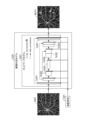
- FIG. 1 is a diagram illustrating an example of a schematic configuration of an image generation system including an image generation device according to a first embodiment.
- 2 is a diagram for explaining the concept of an image generation model held by an output unit in the image generating device according to the first embodiment.
- FIG. 4 is a diagram for explaining learning of an image generation model that an output unit has in the image generating device according to the first embodiment.
- FIG. 10 is a diagram for explaining a calculation target region of a loss calculated when training an image generation model held by an output unit in the image generating device according to the first embodiment.
- FIG. 4 is a diagram showing an example of a GUI screen displayed on a display in the image generating device according to the first embodiment; FIG.
- FIG. 13 illustrates a first modified example of the first embodiment, and is a diagram for explaining a period of time (contrast time) during which FA examination images, which are moving images constituting teacher data used when the image generation model learns, are recorded.
- FIG. 13 is a diagram showing a first modified example of the first embodiment, illustrating an example of the relationship between a contrast effect image, which is a moving image output by an image generation model, and a correct answer image (FA inspection image), which is a moving image constituting the teacher data.
- FA inspection image a correct answer image
- FIG. 13A to 13C are diagrams illustrating an example of an OCTA image and an FA inspection image according to a second modified example of the first embodiment.
- 13 is a flowchart illustrating an example of a processing procedure for aligning an OCTA image and an FA inspection image according to a second modified example of the first embodiment.
- FIG. 11 is a diagram illustrating an example of a schematic configuration of an image generation system including an image generation device according to a second embodiment.
- FIG. 11 is a diagram showing an example of a GUI screen displayed on a display in an image generating device according to a second embodiment.
- 10 is a flowchart showing an example of a processing procedure in a control method for an image generating apparatus according to a second embodiment.
- FIG. 13 is a diagram for explaining the concept of an image generation model held by an output unit in an image generating device according to a third embodiment.
- FIG. 13 is a diagram for explaining the concept of an image generation model held by an output unit in an image generating device according to a third embodiment.
- FIG. 13 illustrates the third embodiment, and is a diagram showing an example of a period in which there are FA inspection images of the left and right eyes constituting the teacher data used when the image generation model learns, and a period in which there are no such images.
- 13 is a diagram for explaining learning of an image generation model that an output unit has in an image generating device according to a third embodiment.
- FIG. 13 illustrates a third modified example of the third embodiment, showing an example of a period with and without FA inspection images constituting training data used when the image generation model learns.
- FIG. 23 illustrates a third modified example of the third embodiment, and is a diagram for explaining an effective pixel area when the immediately subsequent FA inspection image illustrated in FIG. 22 is the FA inspection image captured first in the FA inspection.
- FIG. 13 is a diagram for explaining the concept of an image generation model that an output unit has in an image generating device according to a fourth embodiment.
- FIG. 13 illustrates a fourth embodiment and is a diagram for explaining the presence or absence of an FA inspection image that constitutes training data used when the image generation model is trained.
- FIG. 13 is a diagram for explaining learning of an image generation model that an output unit has in an image generating device according to a fourth embodiment.
- FIG. 13 is a diagram for explaining learning of an image generation model that an output unit has in an image generating device according to a fourth embodiment.
- FIG. 13 is a diagram showing an example of a GUI screen displayed on a display in an image generating device according to a fourth embodiment.
- 13 is a flowchart showing an example of a processing procedure in a control method for an image generating device according to a fourth embodiment.
- FIG. 13 is a diagram for explaining the concept of an image generation model that an output unit has in an image generating device according to a fifth embodiment.
- FIG. 13 is a diagram for explaining learning of an image generation model that an output unit has in an image generating device according to a fifth embodiment.
- FIG. 23 is a flowchart showing an example of a processing procedure in a control method for an image generating device according to a sixth embodiment.
- FIG. 23 is a diagram showing an example of a GUI screen displayed on a display in an image generating device according to a seventh embodiment.
- FIG. 23 is a diagram illustrating an example of a schematic configuration of an image generation model generating device according to an eighth embodiment.
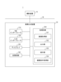
- FIG. 1 is a diagram showing an example of the schematic configuration of an image generation system 1 including an image generation device 20 according to the first embodiment.
- the image generation system 1 includes a photographing device 10, an image generation device 20, and a network 30.
- the photographing device 10 and the image generation device 20 are connected to each other so as to be able to communicate with each other via the network 30.
- the schematic configuration of the image generation system 1 shown in FIG. 1 is an example, and the number of each device may be changed as desired.
- devices not shown in FIG. 1 may be connected to the network 30.
- the image generating device 20 includes a network interface 210, an input interface 220, a display 230 which is a display device, a memory circuit 240, and a processing circuit 250.
- the NW interface 210 is communicatively connected to the input interface 220, the display 230, the memory circuit 240, and the processing circuit 250.
- the NW interface 210 controls the transmission and communication of various information and data (including image data) between each device connected via the network 30.
- the NW interface 210 is realized by a network card, a network adapter, a NIC (Network Interface Controller), etc.
- the input interface 220 is communicatively connected to the NW interface 210, the display 230, the memory circuit 240, and the processing circuit 250.
- the input interface 220 converts the input operation received from the operator into an input signal, which is an electrical signal, and inputs it to the processing circuit 250, etc.
- the input interface 220 can be realized by a trackball, a switch button, a mouse, a keyboard, etc.
- the input interface 220 can be realized by a touch pad that performs input operations by touching the operation surface, a touch screen in which the display screen and the touch pad are integrated, a non-contact input circuit using an optical sensor, a voice input circuit, etc.
- the input interface 220 is not limited to only those that have physical operation parts such as a mouse and a keyboard.
- the input interface 220 also includes a component that receives an electrical signal corresponding to an input operation from an external input device provided separately from the image generating device 20 and inputs this electrical signal as an input signal to the processing circuit 250, etc.
- the display 230 is communicatively connected to the NW interface 210, the input interface 220, the memory circuit 240, and the processing circuit 250.
- the display 230 displays various information and data (including image data) output from the processing circuit 250.
- the display 230 is realized by a liquid crystal display, a CRT (Cathode Ray Tube) display, an organic EL display, a plasma display, a touch panel, etc.
- the memory circuit 240 is communicatively connected to the NW interface 210, the input interface 220, the display 230, and the processing circuit 250.
- the memory circuit 240 stores various types of information and data (including image data). Furthermore, the memory circuit 240 stores programs that the processing circuit 250 reads and executes to realize various functions.
- the memory circuit 240 is realized by semiconductor memory elements such as RAM (Random Access Memory) and flash memory, a hard disk, an optical disk, etc.
- the processing circuit 250 comprehensively controls the operation of the image generating device 20 and performs various processes.
- the processing circuit 250 includes an image acquisition unit 251, an output unit 252, and a display unit 253.
- a program for causing each component (251 to 253) of the processing circuit 250 to function is stored in the storage circuit 240 in the form of a program executable by a computer.
- the processing circuit 250 is a processor that realizes the functions of each component (251 to 253) by reading and executing a program from the storage circuit 240.
- the processing circuit 250 is described as a single processor that realizes the image acquisition unit 251, the output unit 252, and the display unit 253, but the processing circuit 250 may be configured by combining multiple independent processors. In this case, each processor in the multiple independent processors that make up the processing circuit 250 may realize the functions of each component (251 to 253) by executing a program.
- the processing circuit 250 may take a form in which it reads out and executes the corresponding program from each memory circuit.
- processor may refer to, for example, a CPU (Central Processing Unit) or a GPU (Graphical Processing Unit).
- processor may refer to, for example, an application specific integrated circuit (ASIC).
- ASIC application specific integrated circuit
- processor may refer to, for example, a programmable logic device (e.g., a simple programmable logic device (SPLD)).
- SPLD simple programmable logic device
- processor may refer to, for example, a complex programmable logic device (CPLD).
- processor may refer to, for example, a field programmable gate array (FPGA).
- the processor realizes the functions of each component by reading and executing a program stored in the memory circuit 240. Note that instead of storing a program in the memory circuit 240, the processor may be configured to directly incorporate the program into the circuitry of the processor. In this case, the processor realizes the functions of each component by reading and executing a program incorporated in the circuitry.
- the motion contrast data is data obtained by repeatedly photographing the same cross section of the measurement object (in this embodiment, the fundus of the test eye) with the OCT device and detecting the temporal change of the measurement object between the photographs.
- This motion contrast data is obtained, for example, by calculating the temporal change of the phase, vector, and intensity of the complex OCT signal from the difference, ratio, correlation, etc.
- a two-dimensional front image of the fundus of the test eye is generated as an OCTA image.
- an OCTA image of any range such as the superficial layer, deep layer, outer layer, or choroidal vascular network
- the type of OCTA image is not limited to this, and OCTA images with different depth ranges set by changing the reference layer and offset value may be generated.
- an OCTA image of the superficial layer of the fundus of the test eye and a fluorescein fundus angiography (FA) examination image are used as examples for explanation.
- the output unit 252 has a function of outputting a contrast effect image depicting a contrast effect corresponding to a contrast time including at least one contrast time based on an OCTA image, which is a medical image acquired by the image acquisition unit 251.
- the output unit 252 outputs a contrast effect image equivalent to a still image when the contrast time includes only one contrast time, and outputs a contrast effect image equivalent to a moving image composed of multiple still images when the contrast time includes multiple contrast times.
- the output unit 252 outputs a moving image as a contrast effect image corresponding to a contrast time including multiple contrast times.
- the contrast effect image in this embodiment is a pseudo contrast image like an FA examination image in a moving image format depicting a change in the contrast effect over time, as acquired in an FA examination.
- the output unit 252 in this embodiment sets a predetermined FPS (Frames Per Second), such as 10 frames per second, at which the change in the contrast effect is easily observed, as the playback speed of the contrast effect image, which is a moving image.
- the output unit 252 may output the contrast effect image, for example, to the memory circuitry 240, or may output it to another device (not shown) via the NW interface 210 and the network 30, and may simultaneously output it to the display 230.
- the display unit 253 has a function of displaying the contrast effect image output from the output unit 252 on the display 230 so that the operator can easily observe it.
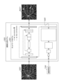
- FIG. 2 is a diagram for explaining the concept of the image generation model 2520 possessed by the output unit 252 in the image generating device 20 according to the first embodiment.
- the image generation model 2520 shown in FIG. 2 is a model including an image processing system that outputs a contrast effect image, for example, by rule base or machine learning (particularly, deep learning technology).
- the image generation model 2520 is a model trained using training data including, for example, a medical image group related to a medical image, a contrast image group related to the medical image group, and an imaging condition group related to the contrast image group.
- the image generation model 2520 including an image processing system using deep learning technology is described.
- the image generation model 2520 shown in FIG. 2 has a network model 2521 based on U-Net as an image processing system using deep learning technology.
- U-Net is a well-known network model that uses deep learning technology.
- U-Net is trained with a dataset consisting of a group of paired images of an input image and a corresponding output image.
- an image is input to the image generation model 2520 including a fully trained U-Net, it is possible to output a plausible image that corresponds to the input image according to the tendency of the dataset used for training. For example, it is known that it can be applied to image segmentation processing, image quality improvement, image domain conversion, etc. according to the dataset.
- the image generation model 2520 converts the input image St101, which is a still image, into a tensor and inputs it to the network model 2521, then converts the tensor output by the network model 2521 into a moving image and outputs the output image Mo111.
- a U-Net is used as the network model 2521, it is necessary to modify the U-Net.
- a tensor in the explanation of this embodiment refers to a format in which a group of pixel values of an image, etc., is expressed as a multidimensional array, and is the data input/output format for the network model 2521, and it is also assumed that images and tensors can be converted to each other.
- the elements constituting the input tensor are increased, and a shape transformation is performed up to the final layer to output a tensor having a shape of "N ⁇ C out ⁇ H out ⁇ W out ".
- H out is the height of the output tensor
- W out is the width of the output tensor.
- the tensor output from the network model 2521 is divided into N tensors each having a shape of "C out ⁇ H out ⁇ W out ", and each divided tensor group is converted into a video frame image.
- the converted video frame images are linked and output from the image generation model 2520 as an output image Mo111, which is a single video image.
- the shape of the tensor is not limited to the shape shown in the description of this embodiment, and may be other shapes that can achieve the same purpose.
- U-Net is exemplified in this embodiment, other network models that can achieve the same purpose may be adopted.
- two-dimensional images are handled, but in the case of handling three-dimensional images in another embodiment, it is possible to handle it by further adding a depth space to the shape of the tensor described here.
- the dataset is configured as a group of teacher data acquired from multiple test subjects, with a pair of teacher data consisting of an OCTA image, which is a still image obtained by photographing the same test subject (i.e., the subject's eye), and an FA test image, which is a moving image during a period of a specified contrast time (contrast time).
- the contrast time is a time indicating the elapsed time from a reference time point (reference time point), such as the time when the subject is injected with a contrast agent, the time when the first image is taken, or the time when the contrast effect of an organ is first confirmed in the acquired image.
- the period of a specified contrast time is a period defined, for example, as a contrast time from 0 seconds to 60 seconds.
- the FA test image is a moving image of 1 FPS
- some or all of the video frame images that make up the FA inspection image, which is a moving image may be supplemented with the FA inspection image, which is a still image.
- the FA examination image which is a moving image for a specified contrast time period (contrast time)
- the FA examination image which is a moving image for a specified contrast time period (contrast time)
- sampling of the video frame images is performed so that the number of video frame images constituting the FA examination image, which is a moving image constituting the teacher data, is constant for all teacher data.
- the FA examination image which is a moving image constituting the final data set, is constructed with a constant number of video frame images.
- the number of video frame images matches the number of video frame images of the contrast effect image, which is a moving image output by the image generation model 2520.
- the input image and the correct image in the teacher data are aligned.
- the network model 2521 based on U-Net it is preferable to align the OCTA image of the input image in the teacher data acquired by photographing the same test subject with each of the video frame images constituting the FA examination image, which is the correct image.
- the alignment is performed anatomically by manual image processing or image registration processing, the depiction of the contrast effect in the contrast effect image output by the image generation model 2520 becomes closer to the real FA examination image.
- the OCTA image and the FA examination image are images acquired by different types of imaging devices, the depiction is significantly different, and anatomical alignment may be difficult depending on conditions such as the time of contrast.
- the video frame images are deformed and aligned by referring to the anatomical position of the OCTA image.
- the remaining video frame images are deformed and aligned by referring to the anatomical position of the deformed video frame images.
- FIG. 3 is a diagram for explaining the learning of the image generation model 2520 possessed by the output unit 252 in the image generating device 20 according to the first embodiment.
- the same components as those shown in FIG. 2 are given the same reference numerals, and detailed explanations thereof will be omitted.
- learning of the image generation model 2520 using a certain set of teacher data that is, the process of updating the parameter group constituting the network model 2521 included in the image generation model 2520, will be explained using this FIG. 3.
- This series of update processes is repeated using a teacher data group allocated for training in the data set until the network model 2521 has sufficiently learned.
- a teacher data group allocated for training in the data set until the network model 2521 has sufficiently learned.
- an example is shown in which one set of teacher data is used in one update process, but multiple teacher data groups may be used in one update process for purposes such as shortening the learning time and stabilizing the learning process.
- the image generation model 2520 has been sufficiently trained during the learning process, for example by performing an accuracy evaluation using training data for verification, it may be determined that the image generation accuracy is sufficiently high and the learning process may be interrupted (Early Stopping).
- the calculation method based on the following method can be used to evaluate the accuracy and calculate the error (loss) between the FA inspection image (or its tensor) in the teacher data assigned for training or verification and the contrast effect image (or its tensor) output by the image generation model 2520.
- a method of quantifying the error or similarity using a method such as MSE (Mean Squared Error) or SSIM (Structural Similarity) can be used.
- MSE Mel Squared Error
- SSIM Structuretural Similarity
- a calculation method based on a method such as MSE or SSIM is used in either a moving image or still image form.
- a form for moving images can be considered to be a form in which the calculation is performed on a multidimensional array of "width x height x time" of the moving image.
- a form for still images can be considered to be a form in which the calculation is performed on a multidimensional array of "width x height" of the video frame images that make up the moving image, and the result group obtained is averaged.
- the accuracy evaluation and the calculation of the error may be performed by selecting a calculation target in consideration of a semantic area, which is an area in an image included in the learning data and can be divided according to the aspect depicted in the image or information related to the image.
- the semantic area includes masked areas and non-masked areas depicted in the image included in the learning data, printed areas of patient information and shooting information (date and time, imaging protocol name, etc.), and areas related to organ parts and conditions (normal tissue, abnormal tissue, bleeding, inflammation, white spots, treatment scars, etc.).
- the semantic area includes bright or dark areas, high-quality or low-quality areas, and areas where image processing such as alignment has been successful or failed in the image included in the learning data.
- the semantic area is an area in an image included in the learning data that can be divided according to the aspect depicted in the image or information related to the image. For example, in a fundus photograph or an FA examination image acquired by a fundus camera, a masked area (such as an area filled in black) is depicted in the periphery of the image depending on the shooting angle.
- this masked region is a region in which organs are not depicted (does not affect diagnosis)
- the performance and characteristics of the image generation model 2520 may be adjusted by using only the non-masked region that affects the diagnosis as the subject of accuracy evaluation and error (loss) calculation.
- FIG. 4 is a diagram for explaining the target area for calculating the loss calculated when learning the image generation model 2520 of the output unit 252 in the image generating device 20 according to the first embodiment.
- the same components as those shown in FIG. 3 are denoted by the same reference numerals, and detailed description thereof will be omitted.
- a masked area Se151 may be depicted, and the masked area Se151 may be excluded from the accuracy evaluation and error (loss) calculation.
- MSE a calculation method that considers the difference between pixels at the same coordinates between images
- the non-masked area Se152 of the correct answer tensor Te122 of the FA inspection image and the area Se142 in the output tensor Te112 of the contrast effect image that corresponds in coordinates to the non-masked area Se152 are set as the calculation target areas.
- the position and type of the semantic area may change for each moving image frame image constituting the moving image.
- the method of calculating the accuracy evaluation and the error (loss) and the calculation target area may also be changed correspondingly for each moving image frame image.
- the loss Lo132 for updating the parameter group constituting the network model 2521 if only the non-masked area Se152 is targeted, the contrast effect image output by the image generation model 2520 will not depict a state corresponding to the masked area Se151.
- the contrast effect image is one in which the contrast effect for the entire area depicted in the OCTA image input to the image generation model 2520 can be observed.
- a state corresponding to the masked area Se151 may be depicted, and an image closer to a real contrast image may be presented to the operator, thereby reducing the sense of incongruity.
- image processing using known rule bases or machine learning can be used to extract semantic regions to be used for accuracy evaluation and error (loss) calculation.
- the non-masked regions in the FA inspection image are fixed regions determined by the imaging device 10, they may be mechanically extracted and used as the targets for accuracy evaluation and error (loss) calculation.
- the parameters constituting the network model 2521 may be updated by applying a technology related to GAN that uses an image as input, such as Conditional GAN (Generative Adversarial Network), which is a well-known deep learning technology.
- the parameters constituting the network model 2521 may be updated while making the following judgments about the contrast effect image generated by the network model 2521, which corresponds to the Generator Network in Conditional GAN.
- the parameters constituting the network model 2521 may be updated while the Discriminator Network determines whether the contrast effect image appears to be real (an FA examination image) or fake (an FA examination image-like image).
- the image generation model 2520 trained through the above process is able to output a moving contrast effect image that depicts a plausible contrast effect based on the group of teacher data allocated for training from the dataset.
- a pseudo contrast image contrast effect image
- it is able to output a pseudo contrast image (contrast effect image) resembling an FA examination image in a moving image format that depicts the change over time in the contrast effect as obtained in an FA examination.
- FIG. 5 is a diagram showing an example of a GUI screen 400 displayed on the display 230 in the image generating device 20 according to the first embodiment.
- the display unit 253 performs a process of displaying a GUI (Graphical User Interface) screen 400 as shown in FIG. 5 on the display 230. Specifically, the display unit 253 performs a process of displaying a medical image (in this embodiment, an OCTA image) acquired by the image acquisition unit 251 in the image display area 410 of the GUI screen 400 shown in FIG. 5. The display unit 253 also performs a process of displaying a contrast effect image output from the output unit 252 in the image display area 420 of the GUI screen 400 shown in FIG. 5. More specifically, in this embodiment, the display unit 253 performs a process of displaying a contrast effect image of a moving image in the image display area 420.
- a medical image in this embodiment, an OCTA image
- the image display area 420 of the GUI screen 400 is provided with an operation tool that allows the operator to operate the moving image in the contrast effect image.
- the image display area 420 is provided with operation tools such as a play button 421 for starting playback of the moving image, a pause button 422 for temporarily pausing playback of the moving image, a stop button 423 for stopping playback of the moving image, and a seek bar 424 for changing the playback position of the moving image.
- operation tools such as a play button 421 for starting playback of the moving image, a pause button 422 for temporarily pausing playback of the moving image, a stop button 423 for stopping playback of the moving image, and a seek bar 424 for changing the playback position of the moving image.
- the playback of the moving image in the contrast effect image displayed in the image display area 420 may be started automatically, or may be stopped at a playback position corresponding to the contrast time useful for diagnosis.
- an OCTA image which is a medical image acquired by the image acquisition unit 251 is displayed in the image display area 410 in order to improve diagnostic efficiency during observation by comparing it with the contrast effect image displayed in the image display area 420.
- FIG. 6 is a flowchart showing an example of a processing procedure in a control method for the image generating device 20 according to the first embodiment.
- step S101 the image acquisition unit 251 acquires an OCTA image, which is a medical image, from the imaging device 10, for example.
- the output unit 252 generates and outputs a contrast effect image depicting the contrast effect corresponding to the contrast time including contrast times at multiple points in time based on the OCTA image acquired in step S101. Specifically, in this embodiment, the output unit 252 outputs a contrast effect image that is a pseudo contrast image resembling an FA examination image in a moving image format depicting the time-dependent change in the contrast effect corresponding to the contrast time.
- step S103 the display unit 253 displays the OCTA image acquired in step S101 in the image display area 410 of the GUI screen 400 shown in FIG. 5, and displays the contrast effect image of the moving image output in step S102 in the image display area 420.
- step S103 When the processing of step S103 is completed, the processing of the flowchart shown in FIG. 6 is completed.
- the image acquiring unit 251 acquires, for example, an OCTA image, which is a medical image, from the imaging device 10.
- the output unit 252 outputs a contrast effect image (a contrast effect image in a moving image format depicting the contrast effect) depicting the contrast effect corresponding to the contrast time including contrast times at multiple points in time, based on the OCTA image acquired by the image acquiring unit 251.
- a contrast effect image in a moving image format depicting the change in the contrast effect over time is output.
- FIG. 7 shows a first modified example of the first embodiment, and is a diagram for explaining the period of time (contrast time) during which the FA examination images, which are moving images constituting the teacher data used when the image generation model 2520 learns, are recorded.
- the FA examination image which is a moving image constituting the teacher data used when the image generation model 2520 learns, may be an FA examination image of only a part of the period (contrast time) of a predetermined contrast time from time T1 seconds to time T2 seconds, as shown in FIG. 7. It is preferable that the recording period of all FA examination images, when integrated, includes the period (contrast time) of the predetermined contrast time. In addition, when the period (contrast time) of the contrast time to be observed clinically or the period (contrast time) of the contrast time that the operator particularly wants to observe can be specified, it is preferable to include FA examination images that include the period (contrast time) of the contrast time in the teacher data group.
- the FA examination image group (contrast image group) included in the learning data includes more FA examination images taken at the contrast time including the contrast time that the operator wants to observe than FA examination images taken at the contrast time including other contrast times. This is effective because it improves the image generation accuracy (likelihood of depicting the contrast effect image) of the image generation model 2520 for that contrast time period (contrast time). In this case, when calculating the accuracy evaluation and error (loss), only the contrast time corresponding to the playback position of the existing video frame image is considered.
- FIG. 8 shows a first modified example of the first embodiment, and is a diagram showing an example of the relationship between a contrast effect image, which is a moving image output by the image generation model 2520, and a correct answer image (FA test image), which is a moving image constituting the training data.
- a contrast effect image which is a moving image output by the image generation model 2520
- FA test image a correct answer image
- the calculation is performed for the period from contrast time t seconds to T2 seconds, which is the period (contrast time) of the contrast time of the video frame images present in the correct answer image.
- the FA examination image which is a moving image constituting the teacher data
- the FA examination image is not recorded so as to include the period of a specified contrast time (contrast time).
- a pseudo image (contrast effect image) resembling an FA examination image in a moving image format, in which the change in contrast effect over time is depicted, based on the OCTA image.
- This makes it possible to preferably obtain an FA examination image-like image depicting the contrast effect corresponding to the contrast time including the contrast time that the operator wishes to observe, thereby making it possible to support the operator in making a diagnosis.
- the FA examination images in the training data group used by the image generation model 2520 when learning may include FA examination images with different imaging range sizes (i.e., angles of view).
- imaging range sizes i.e., angles of view.
- anatomical alignment may be difficult. For example, if the imaging ranges of the OCTA image and the FA examination image are almost the same, common parts and blood vessels of the test subject (in this embodiment, the test eye) are both depicted, making it easier to achieve anatomical alignment.
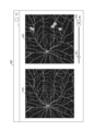
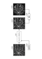
- FIG. 9 shows a second modified example of the first embodiment, and is a diagram showing an example of an OCTA image and an FA inspection image.
- FIG. 9 shows a wide-area OCTA image Im10 obtained by capturing a wide area, a wide-area FA inspection image Im20 obtained by capturing a wide area, and a narrow-area FA inspection image Im30 obtained by capturing a narrow area.
- the results of anatomical alignment can be improved by using the wide-area FA inspection image Im20 obtained by capturing a wider area of the same inspection subject.
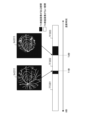
- FIG. 10 shows a second modified example of the first embodiment, and is a flowchart showing an example of a processing procedure for aligning an OCTA image with an FA inspection image.
- step S201 the image generation model 2520 anatomically aligns the wide-area FA inspection image Im20 and the narrow-area FA inspection image Im30 shown in FIG. 9. At this time, since both images are acquired from the same imaging device 10, anatomical alignment can be performed.
- step S202 the image generation model 2520 anatomically aligns the wide-area FA inspection image Im20 and the wide-area OCTA image Im10. At this time, since both images are acquired by capturing a wide area, anatomical alignment is possible.
- step S203 the image generation model 2520 relatively aligns the wide-area OCTA image Im10 and the narrow-area FA inspection image Im30. Specifically, the image generation model 2520 performs the alignment in step S203 by combining the deformation information obtained when the anatomical alignment was performed in step S201 and the deformation information obtained when the anatomical alignment was performed in step S202.
- the manner in which the contrast effect is depicted in the contrast effect image output by the image generation model 2520 can be made closer to that of a real FA examination image.
- a pseudo image (contrast effect image) resembling an FA examination image in a moving image format depicting the change in contrast effect over time can be suitably acquired. This makes it possible to suitably acquire an image resembling an FA examination image depicting the contrast effect corresponding to the contrast time including the contrast time that the operator wishes to observe, thereby making it possible to support the operator in making a diagnosis.
- the OCTA images (group of medical images) constituting the data set may be replaced with other types of images recording the state of the fundus of the subject eye.
- three-dimensional motion contrast data, two-dimensional OCT images, and three-dimensional OCT images acquired by an OCT device may be applied as other types of images.
- fundus images acquired by a fundus camera and SLO (Scanning Laser Ophthalmoscope) images acquired by a scanning laser ophthalmoscope may be applied as other types of images.
- an OCTA image and the other types of images mentioned above may be mixed.
- a fundus image which is a three-channel RGB color image and an OCTA image which is a one-channel grayscale image may be mixed on the channel axis to create a four-channel image.
- an anatomical alignment process is performed.
- the imaging device 10 has the functions of both a fundus camera and an OCT device, the anatomical positions of the acquired fundus image and the OCTA image may match in advance, so there is no need to perform anatomical alignment again.
- FIG. 11 is a diagram showing an example of a schematic configuration of an image generation system 1 including an image generation device 20 according to the second embodiment.
- the same components as those shown in FIG. 1 are denoted by the same reference numerals, and detailed descriptions thereof will be omitted.
- the image generating device 20 according to the second embodiment shown in FIG. 11 has a configuration in which an imaging condition acquisition unit 254 is added to the processing circuit 250 in comparison with the configuration of the image generating device 20 according to the first embodiment shown in FIG. 1.
- the imaging condition acquisition unit 254 has a function of acquiring imaging conditions including contrast time, which includes the contrast time of at least one point in time.
- the output unit 252 generates a contrast effect image for extraction of a moving image depicting a contrast effect corresponding to a contrast time including contrast times at multiple points in time, based on a medical image, which is a still image acquired by the image acquisition unit 251, as in the first embodiment. Furthermore, the output unit 252 extracts a moving image frame image corresponding to the contrast time included in the imaging conditions acquired by the imaging condition acquisition unit 254 from the group of moving image frame images constituting the contrast effect image for extraction, and outputs it as a final contrast effect image.
- the contrast effect image in this embodiment is a pseudo contrast image like an FA examination image in the form of a still image depicting the contrast effect at the specified contrast time, as acquired in an FA examination.
- the imaging condition acquisition unit 254 in this embodiment acquires only information on the contrast time as the imaging conditions.
- FIG. 12 is a diagram showing an example of a GUI screen 400 displayed on the display 230 in the image generating device 20 according to the second embodiment.
- the same components as those shown in FIG. 5 are given the same reference numerals, and detailed descriptions thereof will be omitted.
- the GUI screen 400 in the second embodiment shown in FIG. 12 has a configuration in which a contrast time designation slider 431 and a contrast time designation text box 432 have been added to the configuration of the GUI screen 400 in the first embodiment shown in FIG. 5.
- the contrast time set as an imaging condition can be specified by the operator operating the contrast time specification slider 431 or contrast time specification text box 432 shown in FIG. 12 via the input interface 220.
- FIG. 12 shows an example in which a time "40 seconds" after the reference time is specified as the contrast time.
- the method of specifying the contrast time is not limited to the form described here, and may be replaced by other methods that can achieve the same purpose.
- the GUI screen 400 for the operator to specify the contrast time is described here, a configuration in which a contrast time that is predetermined in the image generating system 1 according to the second embodiment is also possible.
- FIG. 13 is a flowchart showing an example of a processing procedure in a control method for the image generating device 20 according to the second embodiment.
- step S301 the image acquisition unit 251 acquires an OCTA image, which is a medical image, from the imaging device 10, for example.
- the imaging condition acquisition unit 254 acquires imaging conditions including an imaging time including at least one imaging time point. Specifically, in this embodiment, the imaging time is acquired as an imaging condition.
- the output unit 252 generates and outputs a contrast effect image depicting the contrast effect corresponding to the contrast time based on the OCTA image acquired in S301 and the imaging conditions (contrast time) acquired in S302. Specifically, in this embodiment, the output unit 252 outputs a contrast effect image that is a pseudo contrast image resembling an FA examination image in a still image format depicting the contrast effect corresponding to the contrast time.
- step S304 the display unit 253 displays the OCTA image acquired in step S301 in the image display area 410 of the GUI screen 400 shown in FIG. 12, and displays the contrast effect image output in step S303 in the image display area 420.
- step S304 When the processing of step S304 is completed, the processing of the flowchart shown in FIG. 13 is completed.
- the image acquiring unit 251 acquires an OCTA image, which is a medical image, from, for example, the imaging device 10.
- the imaging condition acquiring unit 254 acquires imaging conditions including a contrast time including at least one contrast time point.
- the output unit 252 outputs a contrast effect image depicting the contrast effect corresponding to the contrast time based on the OCTA image acquired by the image acquiring unit 251 and the imaging conditions acquired by the imaging condition acquiring unit 254.
- the contrast time it is possible to preferably obtain an image depicting a contrast effect corresponding to a contrast time including a contrast time at a certain point in time (in this embodiment, the contrast time). More specifically, with the image generating device 20 according to the second embodiment, it is possible to preferably obtain an image similar to an FA examination image depicting a contrast effect corresponding to the contrast time that the operator wishes to observe, making it possible to support the operator in making a diagnosis.
- the schematic configuration of the image generation system including the image generation device according to the third embodiment is similar to the schematic configuration of the image generation system 1 including the image generation device 20 according to the second embodiment shown in FIG. 11.
- the output unit 252 of the third embodiment outputs a contrast effect image, which is a still image depicting the contrast effect corresponding to the contrast time included in the imaging conditions acquired by the imaging condition acquisition unit 254, based on the medical image, which is a still image acquired by the image acquisition unit 251.
- FIG. 14 is a diagram for explaining the concept of an image generation model 2520 possessed by the output unit 252 in the image generating device 20 according to the third embodiment.
- the same components as those shown in FIG. 2 are given the same reference numerals, and detailed descriptions thereof will be omitted.
- the output unit 252 of the third embodiment has an image generation model 2520 shown in FIG. 14.
- the image generation model 2520 shown in FIG. 14 has a network model 2521 based on U-Net as an image processing system using deep learning technology. Note that although U-Net is used as an example in this embodiment, other network models that can achieve the same purpose may also be adopted.
- the image generation model 2520 in FIG. 14 receives an input image St301 corresponding to a still image medical image and a contrast time Ti341, and generates a still image contrast effect image depicting a contrast effect corresponding to the contrast time Ti341 based on the input image St301. Specifically, the image generation model 2520 in FIG. 14 inputs a tensorized version of the input image St301, which is a still image, and a tensorized version of the contrast time Ti341 to the network model 2521. The image generation model 2520 in FIG. 14 then generates a still image from the tensor output by the network model 2521 and outputs it as the output image Mo311.
- a scalar value T indicating the injection time Ti341 is assigned to at least one tensor space axis among the number of channels, height, and width of at least one tensor generated in the intermediate layer of the network model 2521.
- the "tensor generated in the intermediate layer” corresponds to tensors Te351 to Te357 in FIG. 14.
- the scalar value T is assigned to all tensors Te351 to Te357, but, for example, there may be a form in which the scalar value T is assigned only to tensor Te351, or a form in which the scalar value T is assigned to tensors Te355 to Te357, etc.
- the scalar value T is a scalar value determined based on the contrast time Ti341, for example, the contrast time Ti341 in milliseconds divided by a constant.
- the shape of the original tensor before the scalar value T is assigned is "B x C x H x W".
- B is the mini-batch size
- C is the number of channels
- H is the height
- W is the width.
- the number of channels is expanded to the shape of "B x (C + 1) x H x W", and a process is added to fill the values of the expanded tensor region with the scalar value T, and the structure of the network model 2521 is changed so that the expanded tensor can be processed.
- the number of channels is two or more, instead of expanding the tensor, the value of the tensor region for any one channel may be filled with the scalar value T.
- the network model 2521 that normalizes and handles input and output tensors may be used.
- the scalar value T may be normalized, for example, by dividing it by the maximum value that can be input to the image generation model 2520 to convert it to a value between 0 and 1.
- the purpose of the operation on the tensor described using FIG. 14 is to input information about the contrast time to the image generation model 2520 and have the network model 2521 process the OCTA image, which is the input image St301, and the contrast time Ti341. Therefore, this embodiment is not limited to the method described using FIG. 14. Other examples of the method will be described using FIG. 15.
- FIG. 15 is a diagram for explaining the concept of an image generation model 2520 possessed by the output unit 252 in the image generating device 20 according to the third embodiment.
- the same components as those shown in FIG. 2 and FIG. 14 are given the same reference numerals, and detailed description thereof will be omitted.
- a method can be adopted in which the network model 2521 is configured with an unmodified U-Net and a publicly known Decoder network. Specifically, first, a scalar value T indicating the contrast time Ti341 is input to the Decoder network. Then, the upsampled tensor Te361 output from the Decoder network is linked to the tensor of the OCTA image input to the U-Net, and the U-Net outputs the tensor of the contrast effect image. Even with the configuration shown in FIG. 15, the OCTA image, which is the input image St301, and the contrast time Ti341 can be processed by the network model 2521 to obtain a contrast effect image as the output image Mo311 from the image generation model 2520.
- the image generation model 2520 can output a contrast effect image, which is a still image depicting a contrast effect corresponding to an arbitrary contrast time.
- the method of inputting information on the contrast time Ti341 to the network model 2521 is not limited to the method described in this embodiment, and other methods that can achieve the same purpose may be used. For example, a method of manipulating the pixel values of the input image St301 with values related to the contrast time Ti341, or adding a new image channel to the input image St301 and setting pixel values related to the contrast time Ti341 can also be applied. Furthermore, a method of adding and inputting an image generated based on the contrast time Ti341 to the network model 2521 can also be applied.
- the data set is composed of a group of teacher data acquired from multiple test subjects, with a single teacher data set (pair) consisting of an OCTA image, which is a still image acquired by photographing the same test subject, an FA test image taken at a certain contrast time, and the contrast time of the FA test image.
- the test subject is the subject's eye.
- FA test image groups contrast image groups
- contrast time groups imaging condition groups
- FIG. 16 shows a third embodiment, and is a diagram showing an example of periods with and without FA examination images of the left and right eyes that constitute the teacher data used when the image generation model 2520 learns.
- the left and right eyes are alternately photographed after the injection of a contrast agent, so the time periods in which FA examination images exist may be distributed, for example, as shown in FIG. 16.
- a moving image may be captured as an FA examination image.
- a group of moving image frame images that constitute the moving image may be extracted as a group of still images, and a contrast time group corresponding to each moving image frame image may be identified and paired with the corresponding OCTA image of the subject eye, and these may be used as the teacher data.
- FIG. 17 is a diagram for explaining the learning of the image generation model 2520 possessed by the output unit 252 in the image generating device 20 according to the third embodiment.
- the same components as those shown in FIG. 14 and FIG. 15 are given the same reference numerals, and detailed explanations thereof will be omitted.
- learning of the image generation model 2520 using a certain set of teacher data that is, the process of updating the parameter group constituting the network model 2521 included in the image generation model 2520, will be explained using this FIG. 17.
- an input tensor Te302 obtained by tensorizing an OCTA image constituting the teacher data, and a scalar value Se342 indicating a contrast time Ti341 constituting the same teacher data are input to the network model 2521.
- an output tensor Te312 corresponding to a contrast effect image, which is a still image is output from the network model 2521.
- the image generation model 2520 calculates a loss Lo332, which is an error between the correct tensor Te322 obtained by tensorizing an FA examination image taken at the contrast time Ti341, which is a still image constituting the same teacher data, and the output tensor Te312.
- the image generation model 2520 updates the parameter group constituting the network model 2521 so that the loss Lo332 becomes smaller. This series of update processes is repeated using a teacher data group allocated for training from the data set until the network model 2521 has learned sufficiently.
- the image generation model 2520 trained through the above process is able to output a still image contrast effect image depicting a plausible contrast effect based on the training data group from the dataset.
- a pseudo image contrast effect image
- it is able to output a pseudo image (contrast effect image) resembling an FA examination image in still image format depicting the contrast effect corresponding to the specified contrast time, as obtained in an FA examination.
- the processing procedure in the control method of the image generating device 20 according to the third embodiment is similar to the flowchart showing the processing procedure in the control method of the image generating device 20 according to the second embodiment shown in FIG. 13.
- the processing procedure in the control method of the image generating device 20 according to the third embodiment will be described below with reference to the flowchart shown in FIG. 13.
- step S301 the image acquisition unit 251 acquires, for example, an OCTA image, which is a medical image, from the imaging device 10.
- the imaging condition acquisition unit 254 acquires imaging conditions including an imaging time including at least one imaging time point. Specifically, in this embodiment, the imaging time is acquired as an imaging condition.
- the output unit 252 generates and outputs a contrast effect image depicting the contrast effect corresponding to the contrast time based on the OCTA image acquired in S301 and the imaging conditions (contrast time) acquired in S302. Specifically, in this embodiment, the output unit 252 outputs a contrast effect image that is a pseudo contrast image resembling an FA examination image in a still image format depicting the contrast effect corresponding to the contrast time.
- step S304 the display unit 253 displays the OCTA image acquired in step S301 in the image display area 410 of the GUI screen 400 shown in FIG. 12, and displays the contrast effect image output in step S303 in the image display area 420.
- step S304 When the processing of step S304 is completed, the processing of the flowchart shown in FIG. 13 is completed.
- the image acquiring unit 251 acquires an OCTA image, which is a medical image, from, for example, the imaging device 10.
- the imaging condition acquiring unit 254 acquires imaging conditions including a contrast time including at least one contrast time point.
- the output unit 252 outputs a contrast effect image depicting the contrast effect corresponding to the contrast time based on the OCTA image acquired by the image acquiring unit 251 and the imaging conditions acquired by the imaging condition acquiring unit 254.
- the contrast time it is possible to preferably obtain an image depicting a contrast effect corresponding to a contrast time including a contrast time at a certain point in time (in this embodiment, the contrast time). More specifically, with the image generating device 20 according to the third embodiment, it is possible to preferably obtain an image similar to an FA examination image depicting a contrast effect corresponding to the contrast time that the operator wishes to observe, making it possible to support the operator in making a diagnosis.
- the image generating device 20 according to the third embodiment consumes less time and calculation costs for the output unit 252 because it does not output moving images, making it more useful in an environment with performance limitations.
- training of the image generation model 2520 possessed by the output unit 252 does not require teacher data that is a moving image that satisfies a specified contrast time period (contrast time), that is, it does not matter if the FA examination images included in the teacher data have different contrast times. This makes it easier to collect teacher data, which in turn makes it possible to increase the possibility of depicting a contrast effect that is more similar to a real contrast image.
- FIG. 18 is a flowchart showing an example of a processing procedure in a control method for the image generating device 20 according to the first modified example of the third embodiment. According to the processing of the flowchart shown in FIG. 18, it is also possible to output a contrast effect image in a moving image format.
- step S401 the image acquisition unit 251 acquires a medical image, for example, from the imaging device 10.
- a medical image for example, from the imaging device 10.
- an OCTA image is acquired as the medical image.
- the imaging condition acquisition unit 254 acquires a group of imaging conditions in which the contrast time is changed to correspond to a predetermined contrast time period (contrast time). For example, if it is desired to observe the contrast effect at 1-second intervals with the predetermined contrast time period (contrast time) being "0 to 200 seconds," a group of 201 imaging conditions (contrast times) is acquired, which are generated by changing the contrast time from 1 second, 2 seconds, ..., 200 seconds.
- step S403 the output unit 252 outputs a group of contrast effect images corresponding to each of the imaging condition groups (contrast enhancement time groups) acquired in step S402 based on the OCTA images acquired in step S401.
- a group of contrast effect images which are pseudo contrast images resembling FA examination images in a still image format depicting the contrast effect corresponding to each of the contrast enhancement time groups, are output.
- step S404 the output unit 252 outputs the contrast effect images, which are moving images, by using the contrast effect image group output in step S403 as video frame images.
- step S405 the display unit 253 displays the OCTA image acquired in step S401 in the image display area 410 of the GUI screen 400 shown in FIG. 5, and displays the contrast effect image of the moving image output in step S404 in the image display area 420.
- step S405 When the processing of step S405 is completed, the processing of the flowchart shown in FIG. 18 is completed.
- a pseudo FA examination image (contrast effect image) in a moving image format in which the change in contrast effect over time is depicted based on the OCTA image.
- This makes it possible to suitably obtain an FA examination image-like image in which the contrast effect corresponding to the contrast time including the contrast time that the operator wishes to observe is depicted, thereby making it possible to support the operator in making a diagnosis.
- the FA inspection images constituting the data set may be replaced with other types of images that show the state of the contrast effect in the subject being inspected.
- other types of images may include a region division image illustrating the contrast agent leakage area identified from an FA examination image acquired at a certain contrast time, a contour image of the leakage area, and an image in which the FA examination image is colored using a color lookup table.
- the above-mentioned other types of images can be preferably acquired as contrast effect images in which the contrast effect corresponding to the contrast time is depicted based on the OCTA image.
- This makes it possible to preferably acquire an image showing the state of the contrast effect corresponding to the contrast time that the operator wants to observe, and to support the operator in making a diagnosis.
- the FA inspection images constituting the dataset may be interpolated FA inspection images generated by interpolating a group of FA inspection images acquired by photographing the same inspection object over time. More specifically, as shown in FIG. 16, in an FA inspection, there is a "period without FA inspection images" during which no FA inspection images are acquired. By generating an image equivalent to the FA inspection image during this "period without FA inspection images" by an interpolation process and employing it, the image generation accuracy of the image generation model 2520 (likelihood of depicting a contrast effect image) is improved.
- FIG. 19 shows a third modified example of the third embodiment, and is a flowchart showing an example of a processing procedure for generating an interpolated image.
- step S501 the image generation model 2520 identifies a "period without FA examination images" that can be interpolated.
- This "period without FA examination images” that can be interpolated is a period in which FA examination images exist immediately before and after the "period without FA examination images”.
- FIG. 20 shows a third modified example of the third embodiment, and is a diagram showing an example of a period with and without FA examination images that constitute the teacher data used when the image generation model 2520 learns.
- the time period TF3302 (from contrast injection time T1 seconds to T2 seconds) is the "period without FA examination images" that can be interpolated in step S501.
- step S501 When processing in step S501 is completed, proceed to step S502.
- the image generation model 2520 identifies the immediately preceding FA inspection image and the immediately succeeding FA inspection image in the "period without an FA inspection image" that can be interpolated and that was identified in step S501.
- the immediately preceding FA inspection image Im3312 and the immediately succeeding FA inspection image Im3313 are identified in step S502.
- the image generation model 2520 identifies an effective pixel area common to the immediately preceding FA inspection image identified in step S502 and the immediately succeeding FA inspection image.
- the effective pixel area refers to a pixel area in which the contrast effect is depicted.
- FIG. 21 shows a modified example 3 of the third embodiment, and is a diagram for explaining an effective pixel area Re3332 common to the immediately preceding FA inspection image Im3312 and the immediately succeeding FA inspection image Im3313 shown in FIG. 20. In FIG.
- the masked area existing around the immediately preceding FA inspection image Im3312 is not an effective pixel area because the contrast effect is not depicted, and the non-masked area existing in the center is an effective pixel area Re3322 because the contrast effect is depicted.
- the effective pixel area Re3323 in the immediately succeeding FA inspection image Im3313 can be identified.
- the overlapping area between the effective pixel area Re3322 of the immediately preceding FA inspection image Im3312 and the effective pixel area Re3323 of the immediately following FA inspection image Im3313 is the common effective pixel area Re3332 identified in step S503.
- step S503 When processing in step S503 is completed, proceed to step S504.
- the image generation model 2520 When the process proceeds to step S504, the image generation model 2520 generates an interpolated image. Specifically, the image generation model 2520 generates an interpolated image using a group of pixel values of the common effective pixel region Re3332 in the immediately preceding FA inspection image Im3312 and a group of pixel values of the common effective pixel region Re3332 in the immediately following FA inspection image Im3313. In the example shown in FIG. 20, an interpolated image is generated by linearly interpolating the FA inspection image in the "period without FA inspection image (time zone TF3302)" from contrast injection time T1 seconds to T2 seconds.
- step S504 in FIG. 19 the following process is performed to generate an interpolated image.
- a ij be the pixel value at pixel coordinates (x, y) of the immediately preceding FA inspection image Im3312
- B ij be the pixel value at pixel coordinates (x, y) of the immediately following FA inspection image Im3313.
- the pixel value I ij at pixel coordinates (x, y) of the interpolated image at time t seconds is given by the following equation (1).
- I ij (1- ⁇ ) ⁇ A ij + ⁇ B ij ...(1)
- ⁇ t ⁇ (T2-T1)
- pixel values that are always treated as a mask area such as a pixel value of 0, are applied.
- step S504 ends, the processing of the flowchart shown in FIG. 19 ends.
- the process of generating an interpolated image in the flowchart shown in FIG. 19 makes it possible to generate an interpolated image every second for time period TF3302, which is the "period without FA inspection images" in FIG. 20, and add it to the data set, for example.
- FIG. 22 shows a third modified example of the third embodiment, and is a diagram showing an example of a period with and without an FA inspection image constituting the teacher data used when the image generation model 2520 learns.
- FIG. 23 shows a third modified example of the third embodiment, and is a diagram for explaining the effective pixel area Re3331 when the immediately following FA inspection image Im3311 shown in FIG. 22 is the first FA inspection image captured in the FA inspection.
- the FA inspection image Im3311 immediately following a "period without an FA inspection image" such as the time period TF3301 is the first FA inspection image captured in the FA inspection.
- the FA inspection image Im3310 shown in FIG. 23 may be set as the FA inspection image immediately preceding the virtual "period without an FA inspection image.”
- the common effective pixel area Re3331 between the virtual immediately preceding FA inspection image Im3310 and the immediately succeeding FA inspection image Im3311 is the same area as the effective pixel area Re3321 of the immediately succeeding FA inspection image Im3311.
- the third modification of the third embodiment by interpolating FA examination images in the "periods without FA examination images" to enhance the training data of the dataset, it is effective in improving the image generation accuracy (likelihood of depicting a contrast effect image) of the image generation model 2520.
- This makes it possible to preferably obtain an image depicting the contrast effect corresponding to the contrast time that the operator wishes to observe, and to support the operator in making a diagnosis.
- the schematic configuration of the image generation system including the image generation device according to the fourth embodiment is similar to the schematic configuration of the image generation system 1 including the image generation device 20 according to the first embodiment shown in FIG. 1.
- the output unit 252 of the fourth embodiment outputs a group of contrast effect images of still images depicting contrast effects corresponding to contrast times including a plurality of predetermined contrast time groups, based on medical images, which are still images acquired by the image acquisition unit 251.
- FIG. 24 is a diagram for explaining the concept of an image generation model 2520 possessed by the output unit 252 in the image generating device 20 according to the fourth embodiment.
- the same components as those shown in FIG. 2 are given the same reference numerals, and detailed descriptions thereof will be omitted.
- the output unit 252 of the fourth embodiment has an image generation model 2520 shown in FIG. 24.
- the image generation model 2520 shown in FIG. 24 is an image generation model 2520 that includes an image processing system based on deep learning technology.
- the image generation model 2520 shown in FIG. 24 inputs an input image St401 corresponding to a still image medical image. Then, based on the input image St401, the image generation model 2520 shown in FIG. 24 outputs output images Mo411a to Mo411c as a group of contrast effect images of still images depicting contrast effects corresponding to each of a plurality of predetermined contrast enhancement time groups.
- the image generation model 2520 shown in FIG. 24 includes a network model 2521 based on U-Net as an image processing system using deep learning technology, and outputs a group of contrast effect images depicting the contrast effect at N predetermined contrast time groups.
- the N predetermined contrast time groups are, for example, a set of contrast times such as times "30 seconds, 60 seconds, 200 seconds" after a reference time point.
- the predetermined contrast time is a clinically useful contrast time.
- contrast times such as times “before 60 seconds (early contrast)” after a reference time point, times “60 seconds to 200 seconds (mid contrast)” after a reference time point, times “200 seconds or later (late contrast)” after a reference time point, etc., which are considered important in FA examinations.
- the image generation model 2520 shown in FIG. 24 converts the input image St401, which is a still image, into a tensor and inputs it to the network model (2521). Then, the image generation model 2520 shown in FIG. 24 converts the tensor output by the network model (2521) into a still image and outputs it as output images Mo411a to Mo411c. In this case, if U-Net is adopted as the network model (2521), it is necessary to modify U-Net.
- each of the divided tensor groups is converted into a still image, and output images Mo411a to Mo411c are output from the image generation model 2520 as a contrast effect image group.
- the shape of the tensor is not limited to the shape shown in the description of this embodiment, and may be another shape that can achieve the same purpose.
- U-Net is exemplified in this embodiment, other network models capable of achieving the same purpose may be adopted.
- the data set is made up of a group of teacher data acquired from multiple test subjects, with one teacher data set (pair) consisting of a still OCTA image obtained by photographing the same test subject and an FA test image (group) obtained at one or more contrast times out of N predetermined contrast time groups.
- the test subject is the subject's eye.
- Figure 25 shows the fourth embodiment, and is a diagram for explaining the presence or absence of FA examination images that constitute the training data used when the image generation model 2520 learns.
- the collection situation of FA examination images that constitute the training data may be as shown in Figure 25, for example.
- FIGS. 26 and 27 are diagrams for explaining the learning of the image generation model 2520 possessed by the output unit 252 in the image generating device 20 according to the fourth embodiment.
- the image generation model 2520 possessed by the output unit 252 has a network model 2521 shown in FIGS. 26 and 27.
- learning of the image generation model 2520 using a certain set of teacher data that is, the process of updating the parameter group constituting the network model 2521 included in the image generation model 2520, will be explained using FIGS. 26 and 27.
- a loss Lo432b which is the error between the correct tensor Te422b obtained by tensorizing an FA examination image with a contrast time of 60 seconds and the corresponding output tensor Te412b, is calculated and set as the final loss.
- the image generation model 2520 updates the parameter group constituting the network model 2521 so as to reduce the final loss. This series of update processes is repeated using the training data group allocated for training from the data set until the network model 2521 has learned sufficiently.
- FIG. 28 is a diagram showing an example of a GUI screen 400 displayed on the display 230 in an image generating device 20 according to the fourth embodiment.
- the display unit 253 performs a process of displaying a GUI screen 400 as shown in Fig. 28 on the display 230. Specifically, the display unit 253 performs a process of displaying a medical image (in this embodiment, an OCTA image) acquired by the image acquisition unit 251 in the image display area 410 of the GUI screen 400 shown in Fig. 28. The display unit 253 also performs a process of displaying three contrast effect images output from the output unit 252 in the image display areas 420a to 420c of the GUI screen 400 shown in Fig. 28.
- a medical image in this embodiment, an OCTA image
- the image display area 420a displays a contrast effect image corresponding to a contrast time of 30 seconds
- the image display area 420b displays a contrast effect image corresponding to a contrast time of 60 seconds
- the image display area 420c displays a contrast effect image corresponding to a contrast time of 200 seconds. This allows the operator to view the image display areas 420a to 420c on the GUI screen 400 and observe the contrast effect images corresponding to each contrast time.
- FIG. 29 is a flowchart showing an example of a processing procedure in a control method for an image generating device 20 according to the fourth embodiment.
- step S601 the image acquisition unit 251 acquires an OCTA image, which is a medical image, from the imaging device 10, for example.
- the output unit 252 generates and outputs a group of contrast effect images depicting contrast effects corresponding to contrast times including a plurality of predetermined contrast time groups based on the OCTA images acquired in step S601. Specifically, in this embodiment, the output unit 252 outputs a group of contrast effect images that are pseudo contrast images resembling FA examination images in a still image format depicting contrast effects corresponding to a plurality of predetermined contrast time groups.
- step S603 the display unit 253 displays the OCTA image acquired in step S601 in the image display area 410 of the GUI screen 400 shown in Fig. 28, and displays the contrast effect images output in step S602 in the image display areas 420a to 420c. That is, as in the GUI screen 400 shown in Fig. 28, the OCTA image acquired in step S601 and the contrast effect images output in step S602 are displayed side by side.
- step S603 When the processing of step S603 is completed, the processing of the flowchart shown in FIG. 29 is completed.
- the image acquiring unit 251 acquires, for example, OCTA images, which are medical images, from the imaging device 10. Then, based on the OCTA images acquired by the image acquiring unit 251, the output unit 252 outputs a group of contrast effect images (a group of pseudo contrast images resembling FA examination images in the form of still images) depicting contrast effects corresponding to multiple contrast time groups.
- OCTA images which are medical images
- the output unit 252 outputs a group of contrast effect images (a group of pseudo contrast images resembling FA examination images in the form of still images) depicting contrast effects corresponding to multiple contrast time groups.
- the output unit 252 in the fourth embodiment may include a plurality of image generation model groups, and each image generation model 2520 may output a pseudo contrast effect image resembling a still image FA examination image depicting a contrast effect corresponding to one of a plurality of contrast time groups.
- each image generation model 2520 in the plurality of image generation model groups inputs a single OCTA image and outputs a contrast effect image corresponding to a single contrast time.
- the schematic configuration of the image generation system including the image generation device according to the fifth embodiment is similar to the schematic configuration of the image generation system 1 including the image generation device 20 according to the second embodiment shown in FIG. 11.
- the imaging conditions acquired by the imaging condition acquisition unit 254 include other conditions in addition to the contrast time including the contrast time, and can affect the contrast effect image output by the output unit 252 in accordance with the other conditions included in the imaging conditions.
- the other conditions included in the imaging conditions include one or more pieces of information related to the FA examination, such as the presence or absence of individual image processing (optional high image quality processing, etc.) of the FA examination image, the shooting angle of the FA examination image, subject information (gender, age, body part photographed, presence or absence of treatment, etc.), and the model of the FA examination device.
- the imaging condition acquisition unit 254 of the fifth embodiment acquires imaging conditions including other conditions including one or more of the information related to the FA examination described above, in addition to the contrast time including the contrast time at least one time point. That is, the imaging condition acquisition unit 254 of the fifth embodiment acquires imaging conditions including the contrast time described above and information other than the contrast time that is different from the contrast time.
- the output unit 252 of the fifth embodiment outputs a contrast effect image that is a still image depicting the contrast effect, based on the medical image that is a still image acquired by the image acquisition unit 251 and the imaging conditions acquired by the imaging condition acquisition unit 254. At this time, the medical image, the contrast time that is the imaging condition, and information other than the contrast time are input to the image generation model 2520 of the output unit 252.
- FIG. 30 is a diagram for explaining the concept of an image generation model 2520 possessed by the output unit 252 in the image generating device 20 according to the fifth embodiment.
- the same components as those shown in FIGS. 2, 14, and 15 are given the same reference numerals, and detailed descriptions thereof will be omitted.
- the output unit 252 of the fifth embodiment has an image generation model 2520 shown in FIG. 30.
- the image generation model 2520 shown in FIG. 30 has a network model 2521 based on U-Net as an image processing system using deep learning technology. Note that although U-Net is used as an example in this embodiment, other network models that can achieve the same purpose may also be adopted.
- FIG. 31 is a diagram for explaining the learning of the image generation model 2520 of the output unit 252 in the image generating device 20 according to the fifth embodiment.
- the same components as those shown in FIG. 30 are denoted by the same reference numerals, and detailed descriptions thereof will be omitted.
- the image generation model 2520 shown in FIG. 30 inputs an input image St501 corresponding to a still medical image and imaging conditions Co541, and generates a contrast effect image, which is a still image in which a contrast effect is depicted based on the input image St501.
- the image generation model 2520 in FIG. 30 inputs an input tensor Te502 in FIG. 31 obtained by tensorizing the input image St501 in FIG. 30, and an tensor (Sc542) obtained by tensorizing the imaging conditions Co541 in FIG. 30, to the network model 2521.
- the image generation model 2520 in FIG. 30 converts the tensor output by the network model 2521 into a still image, and outputs an output image Mo511 as a contrast effect image.
- a scalar value group Sc542 indicating the imaging condition Co541 is assigned to at least one tensor space axis of the number of channels, height, and width of at least one tensor generated in the intermediate layer of the network model 2521.
- the scalar value group Sc542 is a set of scalar values determined based on a group of information related to the FA examination constituting the imaging condition Co541. For example, information expressed as a continuous value such as contrast time and age is made into a scalar value divided by a constant, for example, as in the third embodiment.
- information that can be expressed as a Boolean value such as the presence or absence of individual image processing and the presence or absence of treatment is made into a scalar value with, for example, False being 0 and True being 1.
- information that can be expressed as a category such as gender, imaging site, imaging angle of view (30 degrees, 55 degrees, etc.), and model of FA inspection device is made into a scalar value obtained by dividing the corresponding category value by a constant, for example.
- each category value may be divided by the maximum category value of 2 as a constant to obtain scalar values of 0, 0.5, and 1, respectively.
- age is treated as a continuous value, but it may be treated as a category as a discrete value.
- it may be treated as an age group and converted to a scalar value based on a category value corresponding to "20s", "30s", "40s", etc.
- the shape of the original tensor before the scalar value group Sc542 is assigned is "B x C x H x W"
- the number of pieces of information included in the imaging condition Co541 i.e., the number of scalar value groups Sc542
- the number of channels is expanded to a shape of "B x (C + M) x H x W”.
- a process of filling each channel region of the expanded tensor region with each of the scalar values constituting the scalar value group Sc542 is added, and the structure of the network model 2521 is changed so that the expanded tensor can be processed.
- the values of the tensor region for any M channels may be filled with each of the scalar values constituting the scalar value group Sc542.
- the purpose is to input a group of information related to the FA inspection to the network model 2521, and the scalar value group Sc542 does not necessarily have to be input to the network model 2521 in the manner described here.
- each of the scalar values constituting the scalar value group Sc542 may be assigned to a different tensor for a tensor group generated in an intermediate layer of the network model 2521.
- the data set is made up of a group of training data acquired from multiple test subjects, with one set (pair) of training data consisting of an OCTA image, which is a still image acquired by photographing the same test subject, an FA test image, and imaging conditions including at least the contrast time of the FA test image.
- the test subject is the subject's eye in this embodiment.
- an input tensor Te502 obtained by tensorizing an OCTA image constituting the teacher data, and a scalar value group Sc542 indicating an imaging condition Co541 constituting the same teacher data are input to the network model 2521.
- an output tensor Te512 corresponding to a contrast effect image, which is a still image is output from the network model 2521.
- the image generation model 2520 calculates a loss Lo532, which is an error between the correct tensor Te522 obtained by tensorizing an FA inspection image, which is a still image constituting the same teacher data, and the output tensor Te512.
- the image generation model 2520 updates the parameter group constituting the network model 2521 so that the loss Lo532 becomes smaller. This series of update processes is repeated using a teacher data group allocated for training from the data set until the network model 2521 has learned sufficiently.
- the image generation model 2520 trained through the above process is able to output a still image contrast effect image depicting a plausible contrast effect based on the training data group allocated for training from the dataset.
- a pseudo contrast image contrast effect image
- it is able to output a pseudo contrast image (contrast effect image) resembling an FA examination image in still image format depicting the contrast effect corresponding to the specified contrast time, as obtained in an FA examination.
- the processing procedure in the control method of the image generating device 20 according to the fifth embodiment is similar to the flowchart showing the processing procedure in the control method of the image generating device 20 according to the second embodiment shown in FIG. 13.
- the processing procedure in the control method of the image generating device 20 according to the fifth embodiment will be described below with reference to the flowchart shown in FIG. 13.
- step S301 the image acquisition unit 251 acquires, for example, an OCTA image, which is a medical image, from the imaging device 10.
- the imaging condition acquisition unit 254 acquires imaging conditions including an imaging time including at least one imaging time point and information other than the imaging time.
- the output unit 252 generates and outputs a contrast effect image depicting the contrast effect based on the OCTA image acquired in S301 and the imaging conditions acquired in S302. Specifically, in this embodiment, the output unit 252 outputs a contrast effect image that is a pseudo contrast image resembling an FA examination image in the form of a still image depicting the contrast effect.
- step S304 the display unit 253 displays the OCTA image acquired in step S301 in the image display area 410 of the GUI screen 400 shown in FIG. 12, and displays the contrast effect image output in step S303 in the image display area 420.
- step S304 When the processing of step S304 is completed, the processing of the flowchart shown in FIG. 13 is completed.
- the image acquiring unit 251 acquires an OCTA image, which is a medical image, from the imaging device 10, for example.
- the imaging condition acquiring unit 254 acquires imaging conditions including an enhancement time including at least one enhancement time point and information other than the enhancement time.
- the output unit 252 then outputs a contrast effect image (a pseudo image resembling an FA examination image in a still image format) in which the contrast effect is depicted based on the OCTA image acquired by the image acquiring unit 251 and the imaging conditions acquired by the imaging condition acquiring unit 254.
- the image generating device 20 according to the fifth embodiment compared to, for example, the third embodiment, it is possible to affect the contrast effect image in accordance with information other than the contrast time, which is another condition included in the imaging conditions.
- the imaging condition acquisition unit 254 in the above-mentioned fifth embodiment may acquire, as imaging conditions, information related to OCTA examination in addition to information related to FA examination, and may also include information related to OCTA examination in the teacher data.
- the information related to OCTA examination includes the model of OCTA examination device, whether or not individual image processing of OCTA images is performed, the depth range for generating OCTA images (superficial layer, deep layer, outer layer, choroidal vascular network, etc.), and the shooting angle of the OCTA image.
- the information related to OCTA examination includes the resolution of the OCTA image, and the scan mode of the OCTA image (Cross, Radial).
- information related to the OCTA examination can also be reflected in the image generation process by the image generating device 20, and a contrast effect image can be obtained in which the contrast effect is depicted based on more detailed features of the input OCTA image.
- This makes it possible to preferably obtain a contrast effect image in which the contrast effect corresponding to the contrast time including the contrast time that the operator wishes to observe is depicted, thereby making it possible to support the operator in making a diagnosis.
- the schematic configuration of the image generation system including the image generation device according to the sixth embodiment is similar to the schematic configuration of the image generation system 1 including the image generation device 20 according to the second embodiment shown in FIG. 11.
- the imaging condition acquisition unit 254 of the sixth embodiment acquires imaging conditions that include information other than the contrast time in addition to the contrast time, which includes at least one contrast time point.
- the information other than the contrast time included in the imaging conditions includes one or more pieces of information that are related to an OCTA examination or an FA examination and can be interpreted as a category.
- the output unit 252 of the sixth embodiment has a group of image generation models in the multiple image generation models 2520.
- Each image generation model in the group of image generation models is constructed to correspond to the type of information that can be interpreted as a category included in the imaging conditions acquired by the imaging condition acquisition unit 254, and has a different quality in terms of depicting the contrast effect.
- the imaging conditions include "depth range information (superficial layer, deep layer, outer layer, choroidal vascular network, etc.)" for OCTA image generation as information related to the OCTA examination
- the output unit 252 has multiple image generation models for each depth range.
- the group of image generation models is, for example, an "image generation model for superficial layer,” an "image generation model for deep layer,” an “image generation model for outer layer,” an “image generation model for choroidal vascular network,” etc.
- the output unit 252 of the sixth embodiment selects an appropriate image generation model from among the multiple image generation models 2520 based on information other than the contrast time included in the imaging conditions. Then, the output unit 252 of the sixth embodiment uses the selected image generation model to output a contrast effect image based on the medical image acquired by the image acquisition unit 251 and the imaging conditions acquired by the imaging condition acquisition unit 254. Specifically, the output unit 252 of the sixth embodiment selects an appropriate image generation model based on the above-mentioned depth range information included in the imaging conditions, and executes image generation processing for the contrast effect image.
- the output unit 252 has two image generation models 2520 corresponding to the presence or absence of individual image processing. Specifically, there is an "image generation model 2520 for with individual image processing" and an “image generation model 2520 for without individual image processing”. In this case, the output unit 252 selects an appropriate image generation model 2520 according to the presence or absence of individual image processing included in the imaging conditions, and executes image generation processing of the contrast effect image. Note that continuous values included in the imaging conditions may also be interpreted as categories.
- categories such as “before 100 seconds”, “after 100 seconds, before 200 seconds”, and “after 200 seconds” may be determined according to the value of the contrast time.
- the imaging conditions may include only the contrast time.
- the image generation model group in the multiple image generation models 2520 each includes a network model 2521 trained with a data set suitable for the imaging conditions used.
- the configuration of the data set in the training of the network model 2521 used when the "depth range information" for OCTA image generation is "superficial layer” is as follows: A group of teacher data obtained from multiple test subjects, with one teacher data set (pair) consisting of an OCTA image generated for the depth range "superficial layer” which is a still image obtained by photographing the same test subject, an FA test image, and imaging conditions including at least the contrast time of the FA test image.
- the test subject is the subject's eye.
- imaging conditions for selecting an image generation model there is no need to input the imaging conditions that led to the selection of the image generation model 2520 (hereinafter, imaging conditions for selecting an image generation model) to the selected image generation model 2520. Therefore, imaging conditions from which the imaging conditions for selecting an image generation model have been removed are input to the image generation model 2520. That is, the imaging conditions are composed of a contrast time including the contrast time of at least one time point, and a group of other imaging conditions required by the selected image generation model 2520. For example, there is no need to input "depth range information" to the "surface image generation model” that is used when the above-mentioned "depth range information" is "surface”. Therefore, the imaging conditions input to the "surface image generation model” do not include “depth range information", but include a contrast time including the contrast time of at least one time point.
- FIG. 32 is a flowchart showing an example of a processing procedure in a control method for an image generating device 20 according to the sixth embodiment.
- step S701 the image acquisition unit 251 acquires an OCTA image, which is a medical image, from the imaging device 10, for example.
- the imaging condition acquisition unit 254 acquires imaging conditions including information other than the contrast time in addition to the contrast time including at least one contrast time point.
- the information other than the contrast time included in the imaging conditions includes one or more pieces of information related to an OCTA examination or an FA examination and that can be interpreted as a category.
- step S703 the output unit 252 selects an appropriate image generation model from among the multiple image generation models 2520 based on information other than the contrast time included in the imaging conditions (information that can be interpreted as a category).
- step S704 the output unit 252 uses the image generation model 2520 selected in step S703 to generate and output a contrast effect image in which the contrast effect is depicted based on the OCTA image acquired in step S701. Specifically, in this embodiment, the output unit 252 outputs a contrast effect image that is a pseudo contrast image resembling an FA examination image in a still image format.
- step S705 the display unit 253 displays the OCTA image acquired in step S701 in the image display area 410 of the GUI screen 400 shown in FIG. 12, and displays the contrast effect image output in step S704 in the image display area 420.
- step S705 When the processing of step S705 is completed, the processing of the flowchart shown in FIG. 32 is completed.
- the image acquiring unit 251 acquires, for example, an OCTA image, which is a medical image, from the imaging device 10.
- the imaging condition acquiring unit 254 sets imaging conditions that include information other than the contrast time in addition to the contrast time, which includes at least one contrast time point.
- the output unit 252 selects an appropriate image generation model from among multiple image generation models 2520 based on information other than the contrast time included in the imaging conditions (information that can be interpreted as a category).
- the output unit 252 uses the selected image generation model 2520 to output a contrast effect image in which the contrast effect is depicted based on the OCTA image acquired by the image acquiring unit 251.
- the output unit 252 in the sixth embodiment described above has a group of image generation models in a plurality of image generation models 2520, but the following modified examples can be applied. Specifically, instead of selecting an image generation model 2520 based on information that can be interpreted as a category included in the imaging conditions, all of the image generation model groups may output contrast effect images. Note that in modified example 1 of the sixth embodiment, since no selection of an image generation model 2520 is performed, there is no need to include "information that can be interpreted as a category" in the imaging conditions described above.
- the multiple contrast effect image groups output by the multiple image generation model groups can be displayed on the GUI screen 400 or stored in the memory circuitry 240 for use in other processes. Furthermore, the multiple contrast effect image groups output by the multiple image generation model groups can be transferred to other devices (not shown) via the NW interface 210 and the network 30 for use.
- the output unit 252 in the sixth embodiment described above has a group of image generation models in a plurality of image generation models 2520, but the following modified example can be applied. Specifically, instead of having a group of image generation models, the output unit 252 may have a single image generation model 2520 capable of outputting a group of contrast effect images corresponding to all category values defined in the "information that can be interpreted as a category" included in the imaging conditions.
- the image generation model 2520 of the output unit 252 can output contrast effect images with depth ranges of "superficial layer”, “deep layer”, “outer layer”, and “choroidal vascular network”.
- a group of contrast effect images corresponding to each of "superficial layer”, “deep layer”, “outer layer”, and “choroidal vascular network” is output according to at least the contrast time included in the imaging conditions.
- the imaging conditions since the image generation model 2520 is not selected, it is not necessary for the imaging conditions to include "depth range information", which is "information that can be interpreted as a category".
- the imaging conditions may include "depth range information”, and the image generation model 2520 described above may be processed to output only contrast effect images corresponding to the "depth range information”.
- the schematic configuration of the image generation system including the image generation device according to the seventh embodiment is similar to the schematic configuration of the image generation system 1 including the image generation device 20 according to the second embodiment shown in FIG. 11.
- the output unit 252 of the seventh embodiment simply put, inputs a radiological image, which is a three-dimensional image, as a medical image.
- the output unit 252 of the seventh embodiment then outputs a contrast effect image, which is a pseudo contrast image resembling a contrast 4DCT image in a moving image format in which a contrast effect is depicted based on the radiological image.
- the image acquisition unit 251 of the seventh embodiment acquires a radiological image, which is a three-dimensional image, as a medical image in which the object of examination is a still image acquired by the imaging device 10.
- a radiological image which is a three-dimensional image
- the medical image in this embodiment is specifically assumed to be a three-dimensional CT image, it may also be a radiological image acquired by another imaging device 10.
- the imaging device 10 it is sufficient if the imaging device 10 can acquire a radiological image. For this reason, for example, the imaging device 10 may be replaced by an image management system that stores and manages the radiological images.
- the output unit 252 of the seventh embodiment has one or more image generation models 2520.
- the image generation models 2520 are constructed to correspond to the types of information that can be interpreted as categories included in the imaging conditions acquired by the imaging condition acquisition unit 254, and may have different qualities related to the depiction of the contrast effect.
- the output unit 252 has a group of image generation models in the multiple image generation models 2520 for each imaging site.
- the image generation model groups here are, for example, an "image generation model for the head,” an "image generation model for the chest,” an “image generation model for the abdomen,” etc.
- the output unit 252 of the seventh embodiment selects an image generation model 2520 according to the imaging part information included in the imaging conditions, executes image generation processing, and outputs a contrast effect image, which is a still image.
- the output unit 252 of the seventh embodiment outputs a contrast effect image group, which is a still image, corresponding to each imaging condition.
- the output unit 252 of the seventh embodiment outputs a contrast effect image, which is a moving image, by using the contrast effect image group as a video frame image.
- the contrast effect image, which is a moving image generated here is a three-dimensional video image, and is a pseudo contrast image like a contrast 4DCT image.
- categories such as "under 20's", “20's to 30's", and "over 40's" may be determined according to the subject's age value.
- the image generation model group in the multiple image generation models 2520 includes a network model 2521 trained with a data set suitable for the imaging conditions used.
- the configuration of the data set in the training of the network model 2521 used when the "imaging part information" is "head” is as follows. Specifically, this is a group of teacher data acquired from multiple subjects, with CT images and contrast CT images acquired by photographing the "head" of the same examination subject, and imaging conditions including at least the contrast time of the contrast CT images, being treated as one teacher data set (pair).
- the imaging condition acquisition unit 254 of the seventh embodiment acquires a group of imaging conditions in which the contrast time is changed so as to correspond to a predetermined contrast time period (contrast time). For example, if it is desired to observe the contrast effect at 1 second intervals with the predetermined contrast time period (contrast time) being "from 0 seconds to 1000 seconds," a group of 1001 imaging conditions (contrast times) is acquired by changing the contrast time from 1 second, 2 seconds, ..., 1000 seconds.
- the imaging conditions may also include information that can be interpreted as a category such as "imaging part information.”
- FIG. 33 is a diagram showing an example of a GUI screen 400 displayed on the display 230 in the image generating device 20 according to the seventh embodiment.
- the display unit 253 performs a process of displaying a medical image (in this embodiment, a radiological image) acquired by the image acquisition unit 251 in the image display area 410 of the GUI screen 400 shown in FIG. 33.
- the display unit 253 also performs a process of displaying a contrast effect image output from the output unit 252 in the image display area 420 of the GUI screen 400 shown in FIG. 33.
- the display unit 253 may perform the following display.
- the display unit 253 may display, as shown in Fig. 33, GUI screen components (421 to 424) that allow playback and seek operations in moving images, as well as a tomographic position operation slider 425 and its text box 426 for operating the three-dimensional image.
- a slider 415 and its text box 416 may also be displayed in the image display area 410.
- the processing procedure in the control method of the image generating device 20 according to the seventh embodiment is similar to the flowchart showing the processing procedure in the control method of the image generating device 20 according to the first modified example of the third embodiment shown in FIG. 18.
- the processing procedure in the control method of the image generating device 20 according to the seventh embodiment will be described below with reference to the flowchart shown in FIG. 18.
- the image acquisition unit 251 acquires a medical image, for example, from the imaging device 10.
- a three-dimensional CT image is acquired as the medical image.
- the imaging condition acquisition unit 254 acquires a group of imaging conditions (contrast time group) in which the contrast time is changed to correspond to a specified contrast time period (contrast time).
- step S403 the output unit 252 outputs a group of contrast effect images corresponding to each of the imaging condition groups obtained in step S402 based on the three-dimensional CT images obtained in step S401. Specifically, in step S403, the output unit 252 outputs a group of contrast effect images, which are pseudo contrast images resembling contrast CT images in the form of still images depicting the contrast effect corresponding to the imaging condition group (contrast time group) obtained in step S402.
- step S404 the output unit 252 outputs the contrast effect images, which are moving images, by using the contrast effect image group output in step S403 as video frame images.
- step S405 When the processing of step S405 is completed, the processing of the flowchart shown in FIG. 18 is completed.
- a contrast CT image in a moving format that allows observation of the change in contrast effect over time, i.e., a pseudo image (contrast effect image) resembling contrast 4D CT, based on a CT image.
- a pseudo image contrast effect image
- an image generating device 20 is provided as the generating device, but in the eighth embodiment, an image generation model generating device is provided.
- FIG. 34 is a diagram showing an example of the schematic configuration of an image generation model generating device 50 according to the eighth embodiment.
- the same components as those shown in FIG. 1 and FIG. 11 are denoted by the same reference numerals, and detailed description thereof will be omitted.
- the image generation model generating device 50 includes a memory circuit 240 and a processing circuit 250. Note that in FIG. 34, a device including the memory circuit 240 and the processing circuit 250 is referred to as the image generation model generating device 50, but it may also be configured as the image generating device 50, as in the first to seventh embodiments described above.
- the processing circuit 250 shown in FIG. 34 comprehensively controls the operation of the image generation model generating device 50 and performs various processes.
- the processing circuit 250 includes a learning unit 255.
- a program for causing the processing circuit 250 to function as the learning unit 255 is stored in the memory circuit 240 in the form of a program executable by a computer.
- the processing circuit 250 is a processor that realizes the function of the learning unit 255 by reading and executing a program from the memory circuit 240.
- the learning unit 255 has a function of acquiring a group of teacher data included in a data set for learning an image generation model stored in the memory circuitry 240, and training the image generation model.
- the learning unit 255 trains the image generation model using training data including the medical image group described in the first to seventh embodiments, the contrast image group related to the medical image group, and the imaging condition group related to the contrast image group.
- the imaging condition group is an imaging condition group including a contrast time including at least one contrast time point.
- the learning unit 255 trains an image generation model using the above-mentioned training data, which trains an image generation model that generates a contrast effect image depicting a contrast effect corresponding to the contrast time based on the medical image when a medical image and a contrast time related to the medical image group are input.
- examples of the OCTA image of the surface layer and the FA examination image have been described as images in the field of ophthalmology, but the present invention is not limited to this form.
- the same processing may be performed on the OCTA image of the choroidal vascular network and the indocyanine green fluorescent fundus angiography (IA) examination image.
- the same processing may be performed on the Enface image of the choroidal vascular network generated from OCT and the IA examination image, not limited to the OCTA image of the choroidal vascular network.
- CT images and contrast CT images are used as examples of images in the field of radiology, but the present invention is not limited to this form.
- a similar process may be performed on a contrast CT image of a certain phase and a contrast CT image of a different phase.
- a similar process may be performed on, for example, an MRI image and a contrast CT image obtained from different types of imaging devices.
- the contrast effect image output by the output unit 252 may be processed into another type of image that shows the state of the contrast effect, as described in Modification 2 of the third embodiment, and then displayed. In other words, the contrast effect image output by the output unit 252 does not need to be displayed in its original form.
- the present invention can also be realized by supplying a program that realizes one or more of the functions of the above-mentioned embodiments to a system or device via a network or storage medium, and having one or more processors in the computer of the system or device read and execute the program. It can also be realized by a circuit (e.g., an ASIC) that realizes one or more functions.
- a circuit e.g., an ASIC
- An image acquisition unit for acquiring a medical image
- an output unit that uses an image generation model that receives a medical image and generates a contrast effect image in which a contrast effect is depicted, and outputs a contrast effect image in which a contrast effect corresponding to a contrast time including at least one contrast time point is depicted based on the medical image acquired by the image acquisition unit;
- An image generating device comprising:
- An imaging condition acquisition unit that acquires imaging conditions including the contrast time, 2.
- the image generating device according to configuration 1, wherein the output unit outputs the contrast effect image based on the medical image and the imaging conditions.
- the image generation model has a function of inputting the medical image and the contrast time to generate the contrast effect image;
- the image generation device according to any one of configurations 1 to 3, wherein the image generation model is a model trained using training data including a medical image group related to the medical image, a contrast image group related to the medical image group, and an imaging condition group related to the contrast image group.
- the image generating device characterized in that the image generation model is a model trained based on semantic regions, which are regions in an image included in the training data and can be divided according to the manner in which the image is depicted or information related to the image.
- the image generating device according to any one of configurations 1 to 8, wherein the image generation model inputs the medical image, the contrast enhancement time, and information other than the contrast enhancement time.
- the output unit has a plurality of the image generation models, The image generating device according to configuration 9, wherein the output unit selects an appropriate image generation model from among the plurality of image generation models based on information other than the contrast time, and outputs the contrast effect image based on the medical image and the imaging conditions using the selected image generation model.
- An image acquisition unit for acquiring a medical image
- an output unit that uses an image generation model that receives a medical image and generates a contrast effect image in which a contrast effect is depicted, and outputs a contrast effect image in which a contrast effect corresponding to the contrast time is depicted based on the medical image acquired by the image acquisition unit and the contrast time;
- An image generating device comprising:
- An image acquisition unit for acquiring a medical image
- an output unit that uses an image generation model that receives a medical image and generates a contrast effect image in which a contrast effect is depicted, and outputs a plurality of contrast effect images in which a contrast effect is depicted as a moving image based on the medical image acquired by the image acquisition unit;
- An image generating device comprising:
- An image generating method comprising:
- An image generating method comprising:
- An image generating method comprising:
- a learning method comprising: a learning step of learning an image generation model that uses learning data including a medical image group, a contrast image group related to the medical image group, and an imaging condition group related to the contrast image group, the imaging condition group including a contrast time including at least one contrast time point, to generate a contrast effect image in which a contrast effect corresponding to the contrast time is depicted based on the medical image when a medical image related to the medical image group and the contrast time are input.
- Program 1 A program for causing a computer to function as each unit of the image generating device according to any one of configurations 1 to 17.
Landscapes
- Health & Medical Sciences (AREA)
- Engineering & Computer Science (AREA)
- Life Sciences & Earth Sciences (AREA)
- Physics & Mathematics (AREA)
- Medical Informatics (AREA)
- General Health & Medical Sciences (AREA)
- Biomedical Technology (AREA)
- Biophysics (AREA)
- Public Health (AREA)
- Heart & Thoracic Surgery (AREA)
- Veterinary Medicine (AREA)
- Molecular Biology (AREA)
- Surgery (AREA)
- Animal Behavior & Ethology (AREA)
- Theoretical Computer Science (AREA)
- Ophthalmology & Optometry (AREA)
- Nuclear Medicine, Radiotherapy & Molecular Imaging (AREA)
- Radiology & Medical Imaging (AREA)
- General Physics & Mathematics (AREA)
- Computer Vision & Pattern Recognition (AREA)
- High Energy & Nuclear Physics (AREA)
- Optics & Photonics (AREA)
- Pathology (AREA)
- Pulmonology (AREA)
- Hematology (AREA)
- Quality & Reliability (AREA)
- Signal Processing (AREA)
- Image Analysis (AREA)
- Algebra (AREA)
- Mathematical Optimization (AREA)
- Mathematical Physics (AREA)
- Pure & Applied Mathematics (AREA)
- Mathematical Analysis (AREA)
- Apparatus For Radiation Diagnosis (AREA)
- Eye Examination Apparatus (AREA)
Priority Applications (1)
| Application Number | Priority Date | Filing Date | Title |
|---|---|---|---|
| US19/272,294 US20250349011A1 (en) | 2023-01-20 | 2025-07-17 | Image generation apparatus, image generation method, training method, and non-transitory computer-readable storage medium |
Applications Claiming Priority (2)
| Application Number | Priority Date | Filing Date | Title |
|---|---|---|---|
| JP2023-007580 | 2023-01-20 | ||
| JP2023007580A JP2024103312A (ja) | 2023-01-20 | 2023-01-20 | 画像生成装置、画像生成方法、学習方法、並びに、プログラム |
Related Child Applications (1)
| Application Number | Title | Priority Date | Filing Date |
|---|---|---|---|
| US19/272,294 Continuation US20250349011A1 (en) | 2023-01-20 | 2025-07-17 | Image generation apparatus, image generation method, training method, and non-transitory computer-readable storage medium |
Publications (1)
| Publication Number | Publication Date |
|---|---|
| WO2024154581A1 true WO2024154581A1 (ja) | 2024-07-25 |
Family
ID=91955887
Family Applications (1)
| Application Number | Title | Priority Date | Filing Date |
|---|---|---|---|
| PCT/JP2023/047234 Ceased WO2024154581A1 (ja) | 2023-01-20 | 2023-12-28 | 画像生成装置、画像生成方法、学習方法、並びに、プログラム |
Country Status (3)
| Country | Link |
|---|---|
| US (1) | US20250349011A1 (https=) |
| JP (1) | JP2024103312A (https=) |
| WO (1) | WO2024154581A1 (https=) |
Citations (4)
| Publication number | Priority date | Publication date | Assignee | Title |
|---|---|---|---|---|
| JP2020146455A (ja) * | 2019-03-06 | 2020-09-17 | キヤノンメディカルシステムズ株式会社 | 医用画像処理装置 |
| JP2020536638A (ja) * | 2017-10-09 | 2020-12-17 | ザ ボード オブ トラスティーズ オブ ザ レランド スタンフォード ジュニア ユニバーシティー | 深層学習を用いた医用イメージングの造影剤用量削減 |
| JP2022169790A (ja) * | 2017-11-24 | 2022-11-09 | キヤノンメディカルシステムズ株式会社 | 医用データ処理装置、超音波診断装置及び学習済みモデル生成方法 |
| JP7170897B2 (ja) * | 2019-09-30 | 2022-11-14 | 富士フイルム株式会社 | 学習装置、方法およびプログラム、画像生成装置、方法およびプログラム、並びに画像生成モデル |
-
2023
- 2023-01-20 JP JP2023007580A patent/JP2024103312A/ja active Pending
- 2023-12-28 WO PCT/JP2023/047234 patent/WO2024154581A1/ja not_active Ceased
-
2025
- 2025-07-17 US US19/272,294 patent/US20250349011A1/en active Pending
Patent Citations (4)
| Publication number | Priority date | Publication date | Assignee | Title |
|---|---|---|---|---|
| JP2020536638A (ja) * | 2017-10-09 | 2020-12-17 | ザ ボード オブ トラスティーズ オブ ザ レランド スタンフォード ジュニア ユニバーシティー | 深層学習を用いた医用イメージングの造影剤用量削減 |
| JP2022169790A (ja) * | 2017-11-24 | 2022-11-09 | キヤノンメディカルシステムズ株式会社 | 医用データ処理装置、超音波診断装置及び学習済みモデル生成方法 |
| JP2020146455A (ja) * | 2019-03-06 | 2020-09-17 | キヤノンメディカルシステムズ株式会社 | 医用画像処理装置 |
| JP7170897B2 (ja) * | 2019-09-30 | 2022-11-14 | 富士フイルム株式会社 | 学習装置、方法およびプログラム、画像生成装置、方法およびプログラム、並びに画像生成モデル |
Also Published As
| Publication number | Publication date |
|---|---|
| US20250349011A1 (en) | 2025-11-13 |
| JP2024103312A (ja) | 2024-08-01 |
Similar Documents
| Publication | Publication Date | Title |
|---|---|---|
| JP7341874B2 (ja) | 画像処理装置、画像処理方法、及びプログラム | |
| JP7114358B2 (ja) | 医用画像処理装置、医用画像処理方法及びプログラム | |
| KR102769769B1 (ko) | 질환의 리스크를 추정하기 위한 정보 처리 장치, 정보 처리 방법, 정보 처리 시스템 및 컴퓨터 판독가능 저장 매체 | |
| CN113557714B (zh) | 医学图像处理装置、医学图像处理方法和存储介质 | |
| JP7229881B2 (ja) | 医用画像処理装置、学習済モデル、医用画像処理方法及びプログラム | |
| KR102507711B1 (ko) | 의료용 화상 처리 장치, 의료용 화상 처리 방법, 및 컴퓨터 판독가능 매체 | |
| JP6867117B2 (ja) | 医用画像処理方法及び医用画像処理装置 | |
| KR101277040B1 (ko) | 화상 처리 장치, 그 제어 방법, 화상 처리 시스템 및 컴퓨터 판독가능 저장 매체 | |
| JP5733962B2 (ja) | 眼科装置、眼科装置の制御方法、及びプログラム | |
| JP2016116774A (ja) | 画像処理装置、画像処理方法、画像処理システム、及びプログラム | |
| JP2019208903A (ja) | 医用画像処理装置、医用画像処理方法、及び医用画像処理プログラム | |
| Proniewska et al. | Advanced imaging in interventional cardiology: mixed reality to optimize preprocedural planning and intraprocedural monitoring | |
| WO2024154581A1 (ja) | 画像生成装置、画像生成方法、学習方法、並びに、プログラム | |
| Kugelman et al. | Dual image and mask synthesis with GANs for semantic segmentation in optical coherence tomography | |
| WO2024203203A1 (ja) | 画像生成装置、及び画像生成方法 | |
| US12161497B2 (en) | Medical image display apparatus | |
| CN105451662A (zh) | 用于医学成像与信息显示的方法和系统 | |
| US7907764B2 (en) | Apparatus, program and method for motion analysis in internal body | |
| JP7086630B2 (ja) | 情報処理装置、情報処理方法、及びプログラム | |
| JP2021164663A (ja) | 医用画像処理方法及び医用画像処理装置 | |
| TWI868960B (zh) | 電腦裝置及用於醫學影像辨識的人工智慧模型的深度學習方法 | |
| JP2020188991A (ja) | 医用画像処理装置、医用画像処理プログラム、x線診断装置及びx線診断システム | |
| US20250072862A1 (en) | Circuitry and method | |
| US20260024168A1 (en) | Imaging based on a set of medical-imaging modalities | |
| JP7544567B2 (ja) | 医用データ処理装置及び医用データ処理方法 |
Legal Events
| Date | Code | Title | Description |
|---|---|---|---|
| 121 | Ep: the epo has been informed by wipo that ep was designated in this application |
Ref document number: 23917791 Country of ref document: EP Kind code of ref document: A1 |
|
| NENP | Non-entry into the national phase |
Ref country code: DE |
|
| 122 | Ep: pct application non-entry in european phase |
Ref document number: 23917791 Country of ref document: EP Kind code of ref document: A1 |