WO2024150728A1 - 電池モジュール - Google Patents
電池モジュール Download PDFInfo
- Publication number
- WO2024150728A1 WO2024150728A1 PCT/JP2024/000119 JP2024000119W WO2024150728A1 WO 2024150728 A1 WO2024150728 A1 WO 2024150728A1 JP 2024000119 W JP2024000119 W JP 2024000119W WO 2024150728 A1 WO2024150728 A1 WO 2024150728A1
- Authority
- WO
- WIPO (PCT)
- Prior art keywords
- battery
- recess
- electrode
- protrusion
- battery module
- Prior art date
- Legal status (The legal status is an assumption and is not a legal conclusion. Google has not performed a legal analysis and makes no representation as to the accuracy of the status listed.)
- Ceased
Links
Images









Classifications
-
- H—ELECTRICITY
- H01—ELECTRIC ELEMENTS
- H01G—CAPACITORS; CAPACITORS, RECTIFIERS, DETECTORS, SWITCHING DEVICES, LIGHT-SENSITIVE OR TEMPERATURE-SENSITIVE DEVICES OF THE ELECTROLYTIC TYPE
- H01G11/00—Hybrid capacitors, i.e. capacitors having different positive and negative electrodes; Electric double-layer [EDL] capacitors; Processes for the manufacture thereof or of parts thereof
- H01G11/78—Cases; Housings; Encapsulations; Mountings
-
- H—ELECTRICITY
- H01—ELECTRIC ELEMENTS
- H01G—CAPACITORS; CAPACITORS, RECTIFIERS, DETECTORS, SWITCHING DEVICES, LIGHT-SENSITIVE OR TEMPERATURE-SENSITIVE DEVICES OF THE ELECTROLYTIC TYPE
- H01G11/00—Hybrid capacitors, i.e. capacitors having different positive and negative electrodes; Electric double-layer [EDL] capacitors; Processes for the manufacture thereof or of parts thereof
- H01G11/78—Cases; Housings; Encapsulations; Mountings
- H01G11/82—Fixing or assembling a capacitive element in a housing, e.g. mounting electrodes, current collectors or terminals in containers or encapsulations
-
- H—ELECTRICITY
- H01—ELECTRIC ELEMENTS
- H01M—PROCESSES OR MEANS, e.g. BATTERIES, FOR THE DIRECT CONVERSION OF CHEMICAL ENERGY INTO ELECTRICAL ENERGY
- H01M50/00—Constructional details or processes of manufacture of the non-active parts of electrochemical cells other than fuel cells, e.g. hybrid cells
- H01M50/20—Mountings; Secondary casings or frames; Racks, modules or packs; Suspension devices; Shock absorbers; Transport or carrying devices; Holders
- H01M50/202—Casings or frames around the primary casing of a single cell or a single battery
-
- H—ELECTRICITY
- H01—ELECTRIC ELEMENTS
- H01M—PROCESSES OR MEANS, e.g. BATTERIES, FOR THE DIRECT CONVERSION OF CHEMICAL ENERGY INTO ELECTRICAL ENERGY
- H01M50/00—Constructional details or processes of manufacture of the non-active parts of electrochemical cells other than fuel cells, e.g. hybrid cells
- H01M50/20—Mountings; Secondary casings or frames; Racks, modules or packs; Suspension devices; Shock absorbers; Transport or carrying devices; Holders
- H01M50/204—Racks, modules or packs for multiple batteries or multiple cells
- H01M50/207—Racks, modules or packs for multiple batteries or multiple cells characterised by their shape
- H01M50/216—Racks, modules or packs for multiple batteries or multiple cells characterised by their shape adapted for button or coin cells
-
- H—ELECTRICITY
- H01—ELECTRIC ELEMENTS
- H01M—PROCESSES OR MEANS, e.g. BATTERIES, FOR THE DIRECT CONVERSION OF CHEMICAL ENERGY INTO ELECTRICAL ENERGY
- H01M50/00—Constructional details or processes of manufacture of the non-active parts of electrochemical cells other than fuel cells, e.g. hybrid cells
- H01M50/20—Mountings; Secondary casings or frames; Racks, modules or packs; Suspension devices; Shock absorbers; Transport or carrying devices; Holders
- H01M50/271—Lids or covers for the racks or secondary casings
-
- H—ELECTRICITY
- H01—ELECTRIC ELEMENTS
- H01M—PROCESSES OR MEANS, e.g. BATTERIES, FOR THE DIRECT CONVERSION OF CHEMICAL ENERGY INTO ELECTRICAL ENERGY
- H01M50/00—Constructional details or processes of manufacture of the non-active parts of electrochemical cells other than fuel cells, e.g. hybrid cells
- H01M50/50—Current conducting connections for cells or batteries
-
- H—ELECTRICITY
- H01—ELECTRIC ELEMENTS
- H01M—PROCESSES OR MEANS, e.g. BATTERIES, FOR THE DIRECT CONVERSION OF CHEMICAL ENERGY INTO ELECTRICAL ENERGY
- H01M50/00—Constructional details or processes of manufacture of the non-active parts of electrochemical cells other than fuel cells, e.g. hybrid cells
- H01M50/50—Current conducting connections for cells or batteries
- H01M50/543—Terminals
- H01M50/552—Terminals characterised by their shape
- H01M50/559—Terminals adapted for cells having curved cross-section, e.g. round, elliptic or button cells
-
- H—ELECTRICITY
- H01—ELECTRIC ELEMENTS
- H01M—PROCESSES OR MEANS, e.g. BATTERIES, FOR THE DIRECT CONVERSION OF CHEMICAL ENERGY INTO ELECTRICAL ENERGY
- H01M50/00—Constructional details or processes of manufacture of the non-active parts of electrochemical cells other than fuel cells, e.g. hybrid cells
- H01M50/50—Current conducting connections for cells or batteries
- H01M50/572—Means for preventing undesired use or discharge
- H01M50/584—Means for preventing undesired use or discharge for preventing incorrect connections inside or outside the batteries
- H01M50/588—Means for preventing undesired use or discharge for preventing incorrect connections inside or outside the batteries outside the batteries, e.g. incorrect connections of terminals or busbars
-
- H—ELECTRICITY
- H01—ELECTRIC ELEMENTS
- H01M—PROCESSES OR MEANS, e.g. BATTERIES, FOR THE DIRECT CONVERSION OF CHEMICAL ENERGY INTO ELECTRICAL ENERGY
- H01M50/00—Constructional details or processes of manufacture of the non-active parts of electrochemical cells other than fuel cells, e.g. hybrid cells
- H01M50/50—Current conducting connections for cells or batteries
- H01M50/572—Means for preventing undesired use or discharge
- H01M50/584—Means for preventing undesired use or discharge for preventing incorrect connections inside or outside the batteries
- H01M50/59—Means for preventing undesired use or discharge for preventing incorrect connections inside or outside the batteries characterised by the protection means
- H01M50/593—Spacers; Insulating plates
-
- Y—GENERAL TAGGING OF NEW TECHNOLOGICAL DEVELOPMENTS; GENERAL TAGGING OF CROSS-SECTIONAL TECHNOLOGIES SPANNING OVER SEVERAL SECTIONS OF THE IPC; TECHNICAL SUBJECTS COVERED BY FORMER USPC CROSS-REFERENCE ART COLLECTIONS [XRACs] AND DIGESTS
- Y02—TECHNOLOGIES OR APPLICATIONS FOR MITIGATION OR ADAPTATION AGAINST CLIMATE CHANGE
- Y02E—REDUCTION OF GREENHOUSE GAS [GHG] EMISSIONS, RELATED TO ENERGY GENERATION, TRANSMISSION OR DISTRIBUTION
- Y02E60/00—Enabling technologies; Technologies with a potential or indirect contribution to GHG emissions mitigation
- Y02E60/10—Energy storage using batteries
Definitions
- This disclosure relates to a battery module.
- Patent Document 1 discloses an electrochemical cell in which an electrochemical element is housed within the storage space of a sealed container.
- the sealed container has a base member on which a first current collector is formed, and a lid member fixed to the base member and on which a second current collector is formed, with a storage space being defined between the two members.
- the electrochemical element has a first electrode (lower electrode) and a second electrode (upper electrode).
- An elastic member is disposed between the lid member and the second electrode in the storage space, which presses the second electrode towards the first electrode and provides electrical conductivity between the second electrode and the second current collector.
- a battery module includes a battery having electrodes on the top and bottom and at least one protrusion; a package having an insulating substrate having a first surface, a second surface opposite to the first surface, and a first recess that opens into the first surface and accommodates the battery; a first external electrode located on the second surface; a second external electrode located on the second surface; a first electrode located on the bottom surface of the first recess and electrically connected to the battery and the first external electrode; a second electrode electrically connected to the battery and the second external electrode; an elastic member located on the first electrode and electrically connecting the battery and the first electrode; and a limiting portion that abuts against the protrusion and limits the movement of the battery in a direction away from the bottom surface of the first recess by the elastic force of the elastic member.
- FIG. 1 is a perspective view showing the appearance of an exemplary battery module according to a first embodiment.
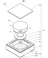
- FIG. 2 is an exploded perspective view of the battery module.
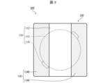
- FIG. 2 is an exemplary bottom view of the battery module.
- FIG. 2 is a top view of the battery module with a lid removed.
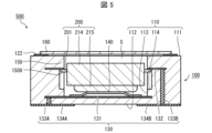
- 5 is a cross-sectional view taken along line VV in FIG. 4.
- 1 is a cross-sectional view showing an example of an internal structure of a battery according to a first embodiment.
- FIG. 4 is a cross-sectional view of a battery module which is a modified example of the battery module.
- FIG. 4 is a cross-sectional view showing a modified example of the battery.
- FIG. 13 is a top view of a battery module which is a modified example of the battery module shown in FIG.
- FIG. 10 is a cross-sectional view taken along line XX in FIG. 9.
- FIG. 2 is a top view of an exemplary battery module according to the first embodiment with a lid removed.
- 12 is a cross-sectional view taken along line XII-XII in FIG. 11 .
- 13 is a cross-sectional view taken along line XIII-XIII in FIG. 11 .
- FIG. 4 is a cross-sectional view of a battery module which is a modified example of the battery module.
- FIG. 11 is a cross-sectional view of an exemplary battery module according to embodiment 3.
- FIG. 4 is a cross-sectional view of a battery module which is a modified example of the battery module.
- FIG. 11 is a cross-sectional view of an exemplary battery module according to embodiment 4.
- FIG. 4 is a cross-sectional view of a battery module which is a modified example of the battery module.
- FIG. 4 is a cross-sectional view of a battery module which is a modified example of the battery module.
- FIG. 4 is a cross-sectional view of a battery module which is a modified example of the battery module.
- FIG. 13 is a top view of an exemplary battery module according to embodiment 5 with the lid removed. 22 is a cross-sectional view taken along line XXII-XXII in FIG. 20 . 13 is a diagram showing a state in which a battery according to embodiment 5 is housed in a battery package.
- FIG. FIG. 13 is a top view of an exemplary battery module according to a sixth embodiment with the lid removed.
- 24 is a cross-sectional view taken along line XXIV-XXIV in FIG. 23.
- FIG. 13 is a diagram showing a state in which a battery according to a sixth embodiment is housed in a battery package.
- FIG. 13 is a cross-sectional view of an exemplary battery module according to embodiment 7.
- the upper electrode of the electrochemical element is electrically connected to the lid member via an elastic member between the lid member and the second electrode, resulting in electrical conduction to the outside at the lid member.
- This disclosure realizes a battery module that is not electrically connected to the outside world except through the external electrodes.
- the lid side of the battery package and the first surface side of the insulating substrate may be referred to as the upper side
- the insulating substrate side of the battery package and the second surface side of the insulating substrate may be referred to as the lower side
- the top-bottom direction may also be referred to as the height direction (thickness direction). This distinction between top and bottom is for convenience, and does not limit the top and bottom when the battery module, etc. is actually used.
- FIG. 1 is a perspective view showing an exemplary appearance of a battery module 500 according to the first embodiment.
- FIG. 2 is an exploded perspective view of the battery module 500 of FIG. 1.
- FIG. 3 is an exemplary bottom view of the battery module 500 of FIG. 1.
- FIG. 4 is a top view of the battery module 500 with the cover 160 removed.
- FIG. 5 is a cross-sectional view taken along the line V-V in FIG. 4.
- FIG. 6 is a diagram showing an example of the internal structure of the battery 200.
- the internal structure of the battery 200 is not shown in FIG. 5.
- the protrusion 201 located on the side surface 214c is not shown in FIG. 6.
- the battery module 500 includes a battery package 100 and one or more batteries 200 housed in a first recess 113 of the battery package 100.
- the battery package 100 may include an insulating substrate 110, a conductive elastic member 140, a limiting portion 150, and a lid 160.
- the limiting portion 150 is a portion that comes into contact with a protrusion 201 of the battery 200, thereby limiting the movement of the battery 200 in a direction away from the bottom surface of a first recess 113 of the insulating substrate 110 due to the elastic force of the elastic member 140.
- the insulating substrate 110 has a first surface 111 and a second surface 112 located on the opposite side to the first surface 111.
- the insulating substrate 110 also has a first recess 113 that opens to the first surface 111 and a second recess 114 that opens to the inner side of the first recess 113.
- one battery 200 is housed in the first recess 113.
- the insulating substrate 110 may be made of an insulating inorganic material.
- the insulating inorganic material includes ceramics such as aluminum oxide sintered body (alumina ceramics), aluminum nitride sintered body, mullite sintered body, or glass ceramic sintered body.
- the battery 200 can be hermetically sealed, so that the battery 200 can be protected from humidity or oxygen in the external environment.
- the insulating substrate 110 may be made of a plurality of laminated insulating layers or a single insulating layer.
- the insulating layer is made of an insulating material such as aluminum oxide sintered body, glass ceramic sintered body, mullite sintered body, or aluminum nitride sintered body.
- the insulating substrate 110 is produced as follows. That is, first, a ceramic green sheet that will become the insulating layer is produced. A raw material powder such as aluminum oxide and silicon oxide is formed into a sheet shape together with an appropriate organic binder and organic solvent to produce a plurality of rectangular ceramic green sheets. Next, these ceramic green sheets are stacked to produce a laminate. The first recess 113 and the second recess 114 are formed by providing through holes in the ceramic green sheets using a mold or the like. The laminate is then fired at a temperature of 1300 to 1600°C to produce the insulating substrate 110.
- the dimensions of the insulating substrate 110 are, for example, a rectangular side length of 1 mm to 20 mm, and a thickness of the insulating substrate 110 of 0.3 mm to 5 mm.
- the dimensions of the first recess 113 of the insulating substrate 110 can be set according to the size of the battery 200.
- the size of the first recess 113 in plan view is slightly larger than the size of the battery 200 in plan view.
- the inner wall surface of the first recess 113 may be parallel to the thickness direction of the insulating substrate 110.
- the depth of the first recess 113 may be deep enough that the battery 200 does not contact the lid 160 when the battery 200 is mounted in the battery package 100.
- the state in which the battery 200 is mounted in the battery package 100 is a state in which the protrusion 201 abuts against the limiting portion 150 and the elastic member 140 is compressed.
- the depth of the first recess 113 may be larger than the height of the battery 200 accommodated in the first recess 113 and the elastic member 140 in a non-compressed state.
- the shape of the first recess 113 in plan view is not limited to a circular shape, and can be changed according to the shape of the battery 200.
- parallel is intended to mean parallel at a level that can be seen, and does not require strict parallelism.
- the insulating substrate 110 has a second recess 114 that opens to the inner side of the first recess 113.
- the insulating substrate 110 may have two second recesses 114.
- the two second recesses 114 may be opposed to each other with the first recess 113 in between.
- the number of second recesses 114 is not limited to two, and multiple second recesses 114 may be formed along the inner circumference of the first recess 113.
- the second recess 114 may be one recess formed over the entire inner circumference of the first recess 113.
- the second recess 114 may be a groove formed over the inner circumference of the first recess 113.
- the number and shape of the second recesses 114 may be determined depending on the number and shape of the protrusions 201, the arrangement position of the protrusions 201 relative to the side surface 214c, etc.
- the insulating substrate 110 has two limiting portions 150, as shown in Figures 4 and 5.
- the two limiting portions 150 are opposed to each other, sandwiching the first recess 113.
- the two limiting portions 150 are located at opposing corners of the insulating substrate 110.
- the attitude of the battery 200 can be stabilized.
- the limiting portions 150 at the corners of the insulating substrate 110, it is possible to easily secure an area for providing the limiting portions 150 while reducing the possibility of a decrease in the strength of the insulating substrate 110, and the battery module 500 can be made smaller.
- the limiting portion 150 is a portion of the insulating substrate 110 that is located above the second recess 114.
- the limiting portion 150 has a locking surface 150X that faces the second surface 112.
- the locking surface 150X can also be said to be the upper surface (ceiling) of the second recess 114.
- the limiting portion 150 may be a protrusion that protrudes from the inner wall surface of the first recess 113 toward the center of the first recess 113.
- the battery package 100 has a limiting portion 150, which limits the movement of the battery 200 in a direction away from the bottom surface of the first recess 113 by the elastic force of the elastic member 140.
- the protrusion 201 of the battery 200 is pressed against the limiting portion 150 by the elastic member 140.
- the battery 200 is fixed in a state where it is pressed against the limiting portion 150.
- the elastic member 140 can absorb manufacturing errors such as variations in the height of the battery 200 and the depth of the first recess 113, as well as expansion and contraction of the battery 200.
- the elastic member 140 can also absorb impacts when assembling the battery module 500.
- the battery package 100 includes a wiring conductor 130 on the surface and inside of the insulating substrate 110.
- the wiring conductor 130 includes a first electrode 131, a second electrode 132, a first connection wiring 133A, a second connection wiring 133B, a first external electrode 134A, and a second external electrode 134B.
- the first electrode 131 is located on the bottom surface of the first recess 113 and is an electrode electrically connected to the first external electrode 134A by the first connection wiring 133A.
- the first electrode 131 may cover the entire bottom surface of the first recess 113.
- the first electrode 131 may extend from the bottom surface of the first recess 113 to the inside of the insulating substrate 110 as shown in FIG. 5.
- the first connection wiring 133A is located in a thick part of the insulating substrate 110, so that the bonding strength with the insulating substrate 110 is excellent.
- the first electrode 131 may be contained within the bottom surface of the first recess 113 in a planar view.
- the first electrode 131 may not extend to the inside of the insulating substrate 110, and the first connection wiring 133A may penetrate from the bottom surface of the first recess 113 to the second surface 112 and connect to the first external electrode 134A.
- the path from the battery 200 to the first external electrode 134A is shorter and has lower resistance, improving the efficiency of extracting power from the battery 200 housed in the first recess 113.
- the second electrode 132 is located on the insulating substrate 110 and is an electrode electrically connected to the second external electrode 134B by the second connection wiring 133B.
- the second electrode 132 is located on the engagement surface 150X of the limiting portion 150.
- the second electrode 132 may extend from the engagement surface 150X of the limiting portion 150 to the inside of the insulating substrate 110.
- the second electrode 132 may cover the entire engagement surface 150X of the limiting portion 150.
- the second electrode 132 may also be located on the bottom surface of the second recess 114.
- the second electrode 132 is located on each engagement surface 150X of the two limiting portions 150 in the insulating substrate 110.
- the first external electrode 134A and the second external electrode 134B are each located on the second surface 112 of the insulating substrate 110.
- the first external electrode 134A and the second external electrode 134B may extend from the second surface 112 of the insulating substrate 110 to the side surface (including the corner between the side surfaces).
- the battery module 500 can be surface mounted on a mounting substrate.
- the elastic member 140 may be any elastic and conductive member, and may be, for example, a plate spring or a disc spring that is convex in a direction away from the bottom surface of the first recess 113, as shown in Figures 2 and 5.
- the elastic member 140 is located on the first electrode 131, and is located between the first electrode 131 and the battery 200 when one or more batteries 200 are housed in the first recess 113. This electrically connects the first electrode 131 and the battery 200 via the elastic member 140. Furthermore, when the battery 200 is housed in the first recess 113, the elastic member 140 biases the battery 200 in a direction away from the bottom surface of the first recess 113.
- the lid 160 may cover the opening of the first recess 113.
- the lid 160 may be, for example, ceramic or metal.
- the lid 160 is electrically insulated from the first electrode 131 and the second electrode 132.
- the lid 160 and the insulating substrate 110 may be joined by soldering, brazing, frit glass, or resin. In this case, the joining is performed by total heating by reflow heating.
- soldering or brazing as shown in FIG. 5, the frame-shaped metal film 122 may be positioned on the first surface 111, and the lid 160 may be joined on the frame-shaped metal film 122.
- the frame-shaped metal film 122 may be formed by metallization on the first surface 111.
- a metal film having the same configuration as the frame-shaped metal film 122 may also be positioned on the underside of the lid 160.
- a nickel film may be formed on the surfaces of the frame-shaped metal film 122 and the lid 160 by plating to improve the bonding strength of the solder joint.
- direct seam welding When joining the metal lid 160 and the frame-shaped metal film 122, direct seam welding, laser welding, or electron beam welding may be used. These welding methods involve localized heating of the joint, and therefore allow airtight or vacuum sealing at a lower temperature than joining using total heating (reflow heating). Sealing at a low temperature reduces the thermal impact on the battery 200, and allows for a low dew point airtight or vacuum environment.
- an iron-nickel (Fe-Ni) alloy or an iron-nickel-cobalt (Fe-Ni-Co) alloy may be used as the material for the lid 160. These alloys have a small thermal expansion difference with ceramics, and are therefore suitable for the lid 160 of the insulating substrate 110.
- the space surrounded by the lid 160 and the insulating substrate 110 i.e., the space housing the battery 200, can be hermetically sealed or vacuum sealed.
- the space S shown in FIG. 5 is the remaining space after the battery 200 is mounted in the storage space.
- the ratio of the volume of the space S to the external volume of the battery module 500 may be set to, for example, 5% to 30%.
- the distance between the lower surface of the lid body 160 and the upper surface of the battery 200 may be, for example, 0.1 mm to 0.8 mm.
- the lid 160 and the top surface of the battery 200 are not in contact with each other, and electrical discharge does not occur to the outside from components other than the external electrodes, such as the lid 160, electrical power can be efficiently extracted from the battery 200 via the first external electrode 134A and the second external electrode 134B.
- the space S may also be sealed in an atmosphere such as a nitrogen atmosphere or an argon gas atmosphere with a dew point of -20 degrees or less, or in a vacuum. In this case, even if the environmental temperature and humidity rise, chemical reactions between the moisture or oxygen and the battery material are suppressed, improving the heat resistance and lifespan of the battery 200.
- an atmosphere such as a nitrogen atmosphere or an argon gas atmosphere with a dew point of -20 degrees or less
- the battery according to the present disclosure may be any battery having electrodes on the top and bottom.
- it may be a coin battery in which battery materials such as an electrolyte material, a positive electrode, a negative electrode, and a separator are placed in a metal container and sealed.
- the electrolyte material may be, for example, a solid electrolyte.
- a coin battery is sometimes called a button battery.
- the battery according to the present disclosure may be a primary battery or a secondary battery.
- the battery according to the present disclosure may include not only a chemical battery but also a power source element such as an electric double layer capacitor.
- the battery 200 is a coin battery. As shown in FIG. 5 and FIG. 6, the battery 200 includes a positive electrode 211, a negative electrode 212, a positive electrode can 214, a negative electrode can 215, and a gasket 216. In addition, a separator 213 is positioned between the positive electrode 211 and the negative electrode 212, which holds the electrolyte material and reduces the occurrence of a short circuit between the positive electrode 211 and the negative electrode 212.
- the positive electrode can 214 is a container that houses the positive electrode 211.
- the positive electrode can 214 may be a cylindrical container having an opening 214a and a bottom 214b.
- the negative electrode can 215 is a container that houses the negative electrode 212.
- the negative electrode can 215 may be a cylindrical (hat-shaped) container having an opening 215a and a bottom 215b.
- the size of the positive electrode can 214 in plan view is slightly larger than the negative electrode can 215 in plan view. Therefore, the negative electrode can 215 is inserted into the positive electrode can 214 through the opening 214a. Also, the battery 200 has a shape with a convex portion on the negative electrode can 215 side, with the bottom 215b protruding from the opening 214a.
- the positive electrode can 214 is the upper electrode
- the negative electrode can is the lower electrode
- the negative electrode can 215 is the upper electrode
- the positive electrode can 214 is the lower electrode.
- the inner peripheral surface of the positive electrode can 214 refers to the surface of the positive electrode can 214 opposite to the side surface 214c.
- the positive electrode can 214 may be made of a metal such as stainless steel or cold-rolled steel.
- the surface of the positive electrode can 214 may be formed with a nickel layer by plating or pressure welding.
- the negative electrode can 215 may be made of a metal such as a clad material in which copper or nickel is pressure-welded to stainless steel.
- the battery 200 may have at least one protrusion 201 on the side surface 214c.
- the protrusion 201 protrudes to the side of the battery 200.
- the protrusion 201 may be a conductive member.
- the protrusion 201 may be integrally molded with the positive electrode can 214.
- the protrusion 201 may be joined to the side surface 214c of the molded positive electrode can 214 by, for example, brazing, soldering, or metal welding. Even when the protrusion 201 is joined to the positive electrode can 214, the material of the protrusion 201 may be the same as that of the positive electrode can 214.
- Other examples of the material of the protrusion 201 include materials commonly used for metal springs. Examples of the material may include the above-mentioned stainless steel, hard steel wire, or piano wire.
- the positive electrode can 214 has a protrusion 201 on the side surface 214c at a position where the battery 200 is housed in the first recess 113 and abuts against at least a part of the limiting portion 150 described later.
- the positive electrode can 214 may have only one protrusion 201 on the side surface 214c, or may have multiple protrusions 201. In this embodiment, the positive electrode can 214 has two protrusions 201 at positions facing each other on the side surface 214c.
- the positive electrode can 214 may also have one annular protrusion 201 along the circumferential direction of the side surface 214c.
- the positive electrode can 214 may also have three or more protrusions 201 evenly positioned along the circumferential direction of the side surface 214c.
- the battery 200 when the battery 200 is mounted in the battery package 100, the battery 200 does not tilt, and the battery 200 can be stably fixed to the battery package 100. In addition, the possibility of the battery 200 coming into contact with the lid 160 due to tilting or movement of the battery 200 can be reduced.
- the protrusion 201 When the battery 200 is housed in the first recess 113, the protrusion 201 abuts against at least a portion of the limiting portion 150. At the point of abutment, the second electrode 132 may be located between the protrusion 201 and the limiting portion 150. This limits the movement of the battery 200 in a direction away from the bottom surface of the first recess 113 due to the elastic force of the elastic member 140.
- the number, size, shape, and position of the protrusions 201 on the side surface 214c may be determined taking into consideration the ease and cost of manufacturing the protrusions 201 as well as the durability against this restriction of movement.
- the protrusions 201 are conductive and are therefore electrically connected to the second electrode 132 when housed in the first recess 113.
- the number, size, shape, and above-mentioned position of the protrusions 201 may be determined taking into consideration the electrical connection with the second electrode 132. In other words, the number, size, shape, and above-mentioned position of the protrusions 201 may be determined so as to reduce the possibility of the battery 200 tilting and causing a conduction failure when the battery 200 is housed in the first recess 113.
- the cross-sectional shape of the protrusion 201 along the radial direction of the battery 200 may be such that the length along the radial direction of the battery 200 increases from the negative electrode can 215 side to the positive electrode can 214 side.
- the cross-sectional shape of the protrusion 201 is a right-angled triangle.
- the battery 200 is inserted into the first recess 113 from the negative electrode can 215 side. Therefore, when the cross-sectional shape of the protrusion 201 is the above-mentioned shape, the possibility that the battery 200 can be smoothly inserted into the first recess 113 can be increased. Therefore, the shape of the protrusion 201 may be determined taking into consideration the ease of insertion into the first recess 113.
- the cross-sectional shape is not limited to a right-angled triangle shape, and may be, for example, a trapezoid, a step shape, or a circular arc shape.
- the cross-sectional shape may also be, for example, a rectangular shape.
- the battery furthest from the bottom surface of the first recess 113 may be the battery 200 that has the protrusion 201.
- the other batteries may not have the protrusion 201 as shown in FIG. 6.
- the elastic member 140 is positioned between the battery 200 and the first electrode 131, so the elastic member 140 is not electrically connected to the lid body 160 or the like and is not electrically connected to the outside of the battery module 500. This prevents discharge to the outside from members other than the external electrodes, such as the lid body 160, so that power can be efficiently extracted from the battery 200 via the first external electrode 134A and the second external electrode 134B.
- the battery module 500 can fix the battery without using conductive resin by housing the battery having the protrusion 201 in the battery package 100 that includes the elastic member 140 and the limiting portion 150. This makes it possible to realize a battery module with high long-term reliability. Furthermore, by including the elastic member 140, it is possible to absorb variations in the height of the battery or the depth of the recess in the battery package.
- the battery module 500 may be sealed at its periphery with a sealing material such as a resin material. This allows the battery package 100A or the battery module 500 to be mounted on a substrate so that neither the first external electrode 134A nor the second external electrode 134B of the battery package 100 shown in FIG. 3 is exposed to the external environment. This prevents an electrical short circuit between the first external electrode 134A and the second external electrode 134B from occurring even if the mounting substrate is flooded with water or is in a humid environment, reducing the possibility of leakage current from the battery module 500.
- a sealing material such as a resin material
- first external electrode 134A and the second external electrode 134B may be arranged so as to be spaced apart from the outer edge of the insulating substrate 110, and a seal pattern may be arranged to surround the periphery of the first external electrode 134A and the second external electrode 134B.
- the seal pattern may be made of a conductive material such as a solderable metal.
- the seal pattern may surround the periphery of the first external electrode 134A and the periphery of the second external electrode 134B, respectively.
- the first external electrode 134A and the second external electrode 134B located inside the seal pattern can be sealed.
- the battery package 100 or the battery module 500 can be mounted on the substrate so that neither the first external electrode 134A nor the second external electrode 134B of the battery package 100 is exposed to the external environment.
- sealing by solder joining can be performed simultaneously with joining the first external electrode 134A and the second external electrode 134B to the electrodes of the mounting substrate by solder.
- ⁇ Battery Modification 1> 7 is a cross-sectional view of a battery module 500A including a battery package 100 and a battery 200A.
- the internal structure of the battery 200A is omitted.
- the battery 200A shown in FIG. 7 is a modified example of the battery 200.
- the protrusion 201A may be a plate-like member (metal plate) having electrical conductivity and flexibility.
- the position of the protrusion 201A on the side surface 214c and the extension direction of the protrusion 201A are determined so that the end of the protrusion 201A abuts against the second electrode 132 when the battery 200A is accommodated in the first recess 113.
- the protrusion 201A may be a member different from the positive electrode can 214 or the negative electrode can 215, and may be, for example, a plate-like member extending from the opening 214a.
- the protrusion 201A may be joined to the side surface 214c by, for example, brazing, soldering, or metal welding. This allows the positive electrode can 214, and therefore the battery 200A, to be easily manufactured.
- the protrusion 201A may be joined so as to be spaced apart from the side surface 214c from the negative electrode can 215 side toward the positive electrode can 214 side. That is, the protrusion 201A may be hook-shaped. For example, the protrusion 201A may be inclined or stepped when viewed from the side from the negative electrode can 215 side toward the positive electrode can 214 side. By joining in this manner, the protrusion 201A can increase the likelihood that the battery 200A can be smoothly inserted into the first recess 113.
- protrusion 201A may be formed, for example, by punching out a claw-shaped portion when punching out positive electrode can 214 from a metal plate, and then bending the claw-shaped portion with a die or the like. Protrusion 201A may be a part of positive electrode can 214 extending outward from opening 214a of positive electrode can 214. In this way, protrusion 201A may be a member integrally formed with positive electrode can 214.
- the protrusion 201A has elasticity in the radial direction of the battery 200A. Therefore, when the battery 200A is inserted into the first recess 113, the protrusion 201A is deformed so as to shrink in the radial direction due to contact with the insulating substrate 110. Therefore, since the protrusion 201A has the above elasticity, it is possible to increase the possibility that the battery 200A can be smoothly inserted into the first recess 113. When the protrusion 201A abuts against the bottom surface of the second recess 114, the radial movement of the battery 200 is also restricted, and the battery 200 can be fixed to the battery package 100.
- the protrusion 201A abuts (is pressed against) the second electrode 132 due to the radial elasticity, thereby achieving a connection with lower resistance.
- Reference numerals 1011 and 1012 in Fig. 8 are diagrams showing modified examples of the battery 200.
- the protrusions 201 located on the side surface 214c of each battery and the internal structure of the battery are omitted.
- the elastic member 140 and the battery 200 are separate, but as shown in Fig. 8, the elastic member 140 may be fixed to the battery 200.
- Fig. 8 shows a case where the elastic member 140 is fixed to the negative electrode can 215.
- the elastic member 140 may be fixed to the positive electrode can 214.
- the battery 200 may have, as the elastic member 140, a single leaf spring positioned so as to be convex in the direction away from the bottom 215b. Also, as shown by reference numeral 1012 in FIG. 8, the battery 200 may have, as the elastic member 140, multiple leaf springs positioned so as to be convex in the direction away from the bottom 215b.
- the battery 200 may have a leaf spring (see FIG. 5) positioned so as to be convex in the direction approaching the bottom 215b as the elastic member 140.
- the battery 200A may also have a coil spring as the elastic member 140.
- the elastic member 140 When two or more batteries are stacked vertically in the battery package 100, the elastic member 140 only needs to be fixed to the bottom of the battery closest to the bottom surface of the first recess 113.
- the elastic member 140 is not limited to the examples shown in Figs. 5 and 8, and may be, for example, a leaf spring of another shape, a coil spring formed from a metal wire, conductive rubber, or a conductive sponge.
- GMS graphene meso sponge
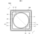
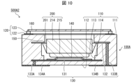
- ⁇ Modifications of Battery Package> 9 and 10 are diagrams showing a battery module 500A2 including a battery package 100A and a battery 200.
- Fig. 9 is a top view showing an example of a battery module 500A2 with the lid 160 removed.
- Fig. 10 is a cross-sectional view taken along line X-X in Fig. 9. The internal structure of the battery 200 is not shown in Fig. 10.
- the battery package 100A differs from the battery package 100 in that it includes a frame 120.
- the battery package 100A has a frame 120 that surrounds the first recess 113 on the first surface 111. This ensures a distance between the top surface of the battery 200 and the lid 160. This further reduces the possibility of the battery 200 and the lid 160 coming into contact.
- the metallic lid 160 and the frame 120 can be joined by seam welding or the like, allowing the battery 200 to be hermetically sealed.
- the frame 120 has a frame-shaped metal film 122 and a metal frame 123 joined to the frame-shaped metal film 122.
- the lid 160 is made of metal
- the metal frame 123 may be joined to the frame-shaped metal film 122 with a brazing material
- the lid 160 may be joined (welded) to the metal frame 123.
- seam welding is resistance welding via the metal frame 123, and is advantageous in terms of localized heating of the joint.
- a current is applied to the lid 160, but since the lid 160 is not electrically connected to the battery 200, the battery 200 is not damaged by the current during seam welding.
- a nickel film may be formed by plating on the surfaces of the frame-shaped metal film 122 and the metal frame 123 to improve bonding with brazing material.
- the metal frame 123 should be made of a material that has a small thermal expansion difference with ceramics, such as an iron-nickel (Fe-Ni) alloy or an iron-nickel-cobalt (Fe-Ni-Co) alloy.
- the frame portion 120 have the frame-shaped metal film 122 and the metal frame body 123, it is possible to further improve the airtightness of the battery module 500A2 while reducing the possibility of contact between the battery 200 and the lid body 160.
- FIG. 11 is a top view of an exemplary battery module 500B according to embodiment 2 with the lid 160 removed.
- FIG. 12 is a cross-sectional view taken along line XII-XII in FIG. 11.
- FIG. 13 is a cross-sectional view taken along line XIII-XIII in FIG. 11. The internal structure of the battery 200B is omitted from illustration in FIGS. 12 and 13.
- the battery module 500B includes a battery package 100B and one or more batteries 200B housed in a first recess 113 of the battery package 100B.
- the battery package 100B has an insulating substrate 110 and a frame 120B surrounding a first recess 113 on a first surface 111 of the insulating substrate 110.
- the frame 120B has an insulating frame 124 located on the first surface 111, a frame-shaped metal film 122 located on the insulating frame 124, and a metal frame 123 bonded to the frame-shaped metal film 122.
- the lid 160 is bonded to the metal frame 123.
- the insulating frame 124 is made of a ceramic material.
- the battery package 100B differs from the insulating substrate 110 in that the second electrode 132 is located on the first surface 111 of the insulating substrate 110. As shown in FIG. 13, in the second embodiment, the second electrode 132 is located on the first surface 111 between the frame portion 120B and the first recess 113.
- the shape of the insulating frame 124 in top view may be any shape that allows the second electrode 132 located on the first surface 111 to be exposed. Also, in a top perspective view, the insulating frame 124 and the limiting portion 150B may overlap. In other words, in a top perspective view, the insulating frame 124 and the second protrusion portion 201Y of the battery 200B described below may overlap. By overlapping the insulating frame 124 and the limiting portion 150B, the strength of the limiting portion 150B can be improved.
- the second recess 114 may open to the first surface 111, and the lower surface of the insulating frame 124 may be the ceiling surface of the second recess 114.
- the limiting portion is the portion of the insulating frame 124 that overlaps with the second recess 114 when viewed from above.
- the locking surface of the limiting portion is the portion of the lower surface of the insulating frame 124 that is exposed to the second recess 114.
- the insulating frame 124 has a convex portion that protrudes from the inner surface of the second recess 114, and the convex portion can function as the limiting portion.
- the insulating frame 124 is interposed between the lid 160 and the second protrusion 201Y, so that the battery 200B is not electrically connected to the lid 160.
- a metal frame may be used instead of the insulating frame 124.
- the metal frame may have a protrusion protruding from the upper surface of the metal frame.
- the protrusion of the metal frame may function as the metal frame 123.
- the battery package 100B does not need to include a frame-shaped metal film 122 and a metal frame 123.
- the height obtained by adding the depth of the first recess 113 and the height of the insulating frame 124 may be deep enough that the battery 200B does not come into contact with the lid 160 when the battery 200B is mounted in the battery package 100B.
- the state in which the battery 200B is mounted in the battery package 100B is a state in which the second protrusion 201Y abuts against the limiting portion 150B and the elastic member 140 is compressed.
- the height obtained by adding the depth of the first recess 113 and the height of the insulating frame 124 may be greater than the overlapping height of the battery 200B housed in the first recess 113 and the elastic member 140 in an uncompressed state.
- the battery 200B may have, as the protrusion 201B, a first protrusion 201X that abuts against the second electrode 132 and a second protrusion 201Y that abuts against the limiting portion 150B.
- the limiting portion 150B is a portion of the insulating substrate 110B that is located between the second recess 114 and the insulating frame 124.
- the positive electrode can 214 has a second protrusion 201Y at a position on the side surface 214c that abuts against at least a part of a limiting portion 150B (described later) when the battery 200B is housed in the first recess 113. This limits the movement of the battery 200B in a direction away from the bottom surface of the first recess 113 by the elastic force of the elastic member 140.
- the positive electrode can 214 has second protrusions 201Y at positions facing each other on the side surface 214c.
- the number, size, and shape of the second protrusions 201Y, and the positions of the second protrusions 201Y on the side surface 214c may be determined in the same manner as the protrusions 201 in embodiment 1.
- the limiting portion 150B does not need to have a second electrode 132. Therefore, unlike the protrusion 201 in embodiment 1, the second protrusion portion 201Y does not need to have the function of being electrically connected to the second electrode 132.
- the positive electrode can 214 also has a first protrusion 201X on the side surface 214c at a position that abuts at least a portion of the second electrode 132 located on the first surface 111 when the battery 200B is housed in the first recess 113.
- the positive electrode can 214 may have only one first protrusion 201X on the side surface 214c, or may have multiple first protrusions 201X.
- the positive electrode can 214 has the first protrusions 201X at positions facing each other at the top of the side surface 214c.
- the number, size, and shape of the first protrusions 201X may be changed as appropriate depending on the position, size, and shape of the second electrode 132. Furthermore, the number, size, and shape of the first protrusions 201X and the position of the first protrusions 201X on the side surface 214c may be determined so as to reduce the possibility of the battery 200B tilting and causing a conduction failure when the battery 200B is housed in the first recess 113. In this embodiment, the shape of the first protrusions 201X is plate-like.
- the first protrusions 201X and the second protrusions 201Y may be positioned alternately along the outer periphery of the battery 200B.
- two first protrusions 201X and two second protrusions 201Y are positioned alternately and at 90° intervals along the circumferential direction of the side surface 214c.
- the first protrusions 201X and the second protrusions 201Y are positioned alternately and at equal intervals along the circumferential direction of the side surface 214c. This prevents the battery 200B from tilting when the battery 200B is mounted in the battery package 100B, and allows the battery 200B to be stably fixed to the battery package 100B. This also reduces the possibility of the battery 200B coming into contact with the lid 160 due to the battery 200B tilting or moving.
- the two limiting portions 150B face each other, sandwiching the first recess 113. Furthermore, the two limiting portions 150B are located at opposing corners of the insulating substrate 110. By arranging the limiting portions 150B in opposing positions, sandwiching the first recess 113, the posture of the battery 200B can be stabilized. Furthermore, by locating the limiting portions 150B at the corners of the insulating substrate 110, it is possible to easily ensure an area for providing the limiting portions 150B while reducing the possibility of a decrease in the strength of the insulating substrate 110, and the battery module 500B can be made smaller.
- the battery package 100B may include three or more second electrodes 132, and the battery 200B may include three or more first protrusions 201X.
- the first protrusion 201X and the second protrusion 201Y may be integrally molded with the positive electrode can 214.
- the first protrusion 201X and the second protrusion 201Y may be joined to the upper surface of the positive electrode can 214 by, for example, brazing, soldering, or metal welding.
- the protrusion 201A shown in FIG. 7 may be used instead of the second protrusion 201Y.
- the material of the first protrusion 201X and the second protrusion 201Y may be the same material as the positive electrode can 214, or may be any of the materials listed as the material of the protrusion 201 in embodiment 1.
- the second protrusion 201Y does not have to have the function of being electrically connected to the second electrode 132. Therefore, the second protrusion 201Y does not have to be conductive.
- the material of the second protrusion 201Y may be, for example, rubber or plastic.
- the second protrusion 201Y may be joined to the side surface 214c by, for example, resin.
- the second electrode 132 is exposed on the top surface of the battery package 100B. This makes it possible to visually check the appearance of the second electrode 132 and the connection between the first protrusion 201X and the second electrode 132 for electrical conduction.
- the insulating substrate 110 has a first recess 113 and a second recess 114, and the limiting portion 150B is an insulating substrate located between the second recess 114 and the insulating frame 124.
- the insulating substrate 110 does not have to have the second recess 114.
- the insulating frame 124 located above the second protrusion 201Y has a convex portion that protrudes from the inner surface of the first recess 113, and the convex portion can function as the limiting portion 150B.
- the limiting portion 150B may be part of the insulating frame 124.
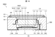
- Fig. 14 is a cross-sectional view of a battery module 500B2 including a battery package 100B and a battery 200B2.
- the battery 200B2 has a conductive member 218 on the upper surface (corresponding to the bottom portion 214b) of the positive electrode can 214.
- the conductive member 218 may be, for example, a plate-shaped member (metal plate) having conductivity.
- a portion of the conductive member 218 protruding from the side surface 214c may function as the first protrusion 201X.
- the conductive member 218 may be joined to the upper surface of the positive electrode can 214 by, for example, brazing, soldering, or metal welding.
- the protrusion 201 may be integrally molded with the positive electrode can 214.
- the material of the conductive member 218 may be the same material as the positive electrode can 214, or may be any of the materials listed as the material of the protrusion 201 in embodiment 1.
- Fig. 15 is a cross-sectional view showing an example of a battery module 500C.
- the internal structure of the battery 200C is omitted in Fig. 15.
- the battery module 500C includes a battery package 100C and a battery 200C accommodated in a first recess 113 of the battery package 100C.
- the battery 200C has a conductive protrusion 201C having elastic force.
- the protrusion 201C is electrically connected to the second electrode 132 located on the inner surface of the second recess 114.
- the second electrode 132 is located on the inner surface (bottom surface) of the second recess 114.
- the second electrode 132 is connected to the second connection wiring 133B via the internal wiring 135 located inside the insulating substrate 110.
- the second electrode 132 may also be located on the upper surface (ceiling) of the second recess 114.
- the protrusion 201C abuts against the limiting portion 150 by the elastic force of the elastic member 140.
- the protrusion 201C is formed by joining a part of a conductive and flexible plate-like member (metal plate) to the side surface 214c and curving or bending the part not joined to the side surface 214c.
- the plate-like member may be joined to the side surface 214c by, for example, brazing, soldering, or metal welding.
- battery 200C having protrusions 201C can be manufactured simply by joining a plate-shaped member to side surface 214c and bending it. This makes it easy to manufacture battery 200C.
- the protrusion 201C having a curved or bent portion has elasticity in the radial direction of the battery 200C. Therefore, when the battery 200C is inserted into the first recess 113, the protrusion 201C is deformed so as to shrink in the radial direction due to contact with the insulating substrate 110. Therefore, since the protrusion 201C has the above elasticity, it is possible to increase the possibility that the battery 200C can be smoothly inserted into the first recess 113.
- the protrusion 201C abuts against the bottom surface of the second recess 114, the radial movement of the battery 200C is also restricted, and the battery 200C can be fixed to the battery package 100C.
- the protrusion 201C abuts (is pressed against) the internal wiring 135 located on the bottom surface of the second recess 114, thereby achieving a connection with lower resistance.
- Fig. 16 is a cross-sectional view of a battery module 500C2 including a battery package 100C and a battery 200C2. In Fig. 16, the internal structure of the battery 200C2 is not shown.
- the battery 200C2 has a conductive member 218C.
- the conductive member 218C2 has a first portion 218X and a second portion 218Y.
- the first portion 218X is a portion of the conductive member 218C2 that extends at least in the radial direction of the battery 200C2.
- the second portion 218Y is a portion of the conductive member 218C2 that extends along the side surface 214c.
- the protrusion 201C2 is located at the end of the second portion 218Y.
- the second portion 218Y is spaced apart from the side surface 214c. Therefore, the second portion 218Y has elasticity in the radial direction of the battery 200C2. Therefore, the second portion 218Y deforms so as to shrink in the radial direction, making it easier to insert the protrusion 201C2 into the first recess 113.
- the cross-sectional shape of protrusion 201C2 along the radial direction of battery 200C2 may be, for example, an arc shape.
- the cross-sectional shape may be a shape in which the length along the radial direction of battery 200C2 increases from the negative electrode can 215 side toward the positive electrode can 214 side.
- the cross-sectional shape may be, for example, a right-angled triangle shape, a trapezoid shape, a stepped shape, or an arc shape.
- the cross-sectional shape may also be, for example, a rectangle.
- First portion 218X may be joined to the top surface of positive electrode can 214 by, for example, brazing, soldering, or metal welding.
- Second portion 218Y may be formed by bending conductive member 218C2.
- Protrusion 201C2 may be joined to an end of second portion 218Y by, for example, brazing, soldering, or metal welding.
- the protrusion 201C2 may be molded integrally with the conductive member 218C2.
- the protrusion 201C2 may also be a curved or bent portion formed by bending the end of the second portion 218Y.
- the conductive member 218C2 may be molded integrally with the positive electrode can 214.
- Fig. 17 is a cross-sectional view showing an example of a battery module 500D.
- the internal structure of the battery 200D is omitted in Fig. 17.
- the battery module 500D includes a battery package 100D and one or more batteries 200D housed in a first recess 113 of the battery package 100D.
- the battery 200D is housed so that the positive electrode can 214 is on the bottom side of the first recess 113 and the negative electrode can 215 is on the opening side of the first recess 113.
- the insulating substrate 110D differs from the insulating substrate 110 of the first embodiment in that it does not have a second recess.
- the battery package 100D has a locking metal fitting 170 that is electrically connected to the first electrode 131.
- the locking metal fitting 170 has a side plate 171 that extends along the inner surface of the first recess 113 in a direction from the bottom surface of the first recess 113 toward the opening of the first recess 113.
- the side plate 171 has a limiting portion 150D. More specifically, the side plate 171 has a through hole 172 whose edge abuts against the protrusion 201D, and the through hole 172 functions as the limiting portion 150D.
- the battery 200D has a protrusion 201D.
- the shape of the protrusion 201D in a cross section along the radial direction of the battery 200D is such that the length along the radial direction of the battery 200D increases from the positive electrode can 214 side to the negative electrode can 215 side.
- the cross-sectional shape of the protrusion 201D is a right-angled triangle.
- the battery 200D has a conductive member 218D extending from the upper surface (negative electrode can 215) of the battery 200D.
- the conductive member 218D may have, for example, a plate-shaped member (metal plate) having electrical conductivity.
- the conductive member 218D may be flexible. In this case, the conductive member 218D has elasticity in the vertical direction.
- the conductive member 218D has a pad 219 at an end of the conductive member 218D that abuts against the second electrode 132. Because the conductive member 218D is elastic, the pad 219 is pressed against the second electrode 132. This reduces the resistance in the connection between the conductive member 218D and the second electrode 132.
- the conductive member 218D may be a plate-shaped member that does not have a pad 219, like the conductive member 218 shown in FIG. 14.
- the conductive member 218D may be joined to the top surface of the battery 200D by, for example, brazing, soldering, or metal welding.
- the pad 219 may be joined to the end of the conductive member 218D by, for example, brazing, soldering, or metal welding.
- the pad 219 may be molded integrally with the conductive member 218D.
- the pad 219 may also be a curved or bent portion formed by bending an end of the conductive member 218D.
- the conductive member 218D may be molded integrally with the negative electrode can 215.
- the configuration of the battery module 500D allows the positive electrode of the battery 200D to be connected to the first electrode 131 and the first external electrode 134A, and the negative electrode to the second electrode 132 and the second external electrode 134B.
- FIG. 18 is a cross-sectional view of a battery module 500D2 including a battery package 100D2 and a battery 200D2. In FIG. 18, the internal structure of the battery 200D2 is not shown.
- Battery 200D2 has conductive member 218D2.
- Conductive member 218D2 differs from conductive member 218D in FIG. 17 in that it is a conductive and flexible plate-shaped member (metal plate) that is bent in the vertical direction.
- the conductive member 218D2 has elasticity in the vertical direction. This can absorb manufacturing errors such as variations in the height direction of the battery 200D2 and variations in the depth of the first recess 113, as well as expansion and contraction of the battery 200D2. This can stabilize the conduction between the second electrode 132 and the conductive member 218D2.
- the conductive member 218D2 is more easily deformed than the conductive member 218D due to having a portion bent in the vertical direction.
- the battery package 100D2 may have a step portion on the first surface 111 of the insulating substrate 110D2 so as to accommodate the bent portion of the conductive member 218D2.
- the second electrode 132 can be formed on the upper surface of the step portion.
- the conductive member 218D2 has a pad 219 at an end of the conductive member 218D2 that abuts against the second electrode 132. Because the conductive member 218D2 is elastic, the pad 219 is pressed against the second electrode 132. This reduces the resistance in the connection between the conductive member 218D2 and the second electrode 132. However, the conductive member 218D2 does not have to have the pad 219.
- Fig. 19 is a cross-sectional view of a battery module 500D3 including a battery package 100D3 and a battery 200D2.
- the battery package 100D3 has a locking metal fitting 170D.
- the locking metal fitting 170D has a side plate 171 that extends from the bottom surface of the first recess 113 toward the opening of the first recess 113 along the inner side surface of the first recess 113.
- the side plate 171 has a limiting portion 150D2. More specifically, the side plate 171 has a bent portion 173 at an end of the side plate 171, and the bent portion 173 functions as the limiting portion 150D2.
- the bent portion 173 is bent from the extension direction of the side plate 171 toward the battery 200D2. This allows the protrusion 201D of the battery 200D2 to abut against the limiting portion 150D2 by the elastic force of the elastic member 140.
- Fig. 20 is a top view showing an example of a battery module 500E with the lid 160 removed.
- Fig. 21 is a cross-sectional view taken along line XXII-XXII in Fig. 20. In Fig. 21, the internal structure of the battery 200E is not shown.
- the battery module 500E includes a battery package 100E and a battery 200E housed in the first recess 113 of the battery package 100E.
- the battery 200E has a conductive member 218E on the upper surface of the positive electrode can 214.
- the conductive member 218E may be, for example, a plate-shaped member (metal plate) having electrical conductivity.
- the conductive member 218E has a protrusion 201E protruding from the side surface 214c when viewed from above.
- the protrusions 201E protrude upward or diagonally upward from the positive electrode can 214.
- the battery 200E has four protrusions 201E at equal intervals along the periphery of the battery 200E.
- the protrusions 201E have through holes 201EP.
- the insulating substrate 110E has a limiting portion 150E that protrudes from the inner wall surface of the first recess 113 toward the center of the first recess 113. That is, the limiting portion 150E is a convex portion that protrudes from the inner surface of the first recess 113.
- the second electrode 132 is located on the lower surface of the limiting portion 150E.
- the limiting portion 150E engages with the through hole 201EP of the protrusion 201E, thereby enabling electrical connection between the battery 200E and the second electrode 132 located on the lower surface of the limiting portion 150E.
- the second electrode 132 may also be located on the upper surface of the limiting portion 150E, which is part of the inner surface of the insulating substrate 110E.
- the force spreading laterally of the protrusion 201E electrically connects the protrusion 201E to the second electrode 132 located on the upper surface of the limiting portion 150E.
- the through hole 201EP By engaging the limiting portion 150E with the through hole 201EP, the movement of the battery 200E in a direction away from the bottom surface of the first recess 113 is restricted.
- the through hole 201EP the battery 200E can be more stably held in the first recess 113.
- the position of the battery 200E in the first recess 113 can be adjusted.
- FIG. 22 is a diagram showing the state when the battery 200E is housed in the battery package 100E.
- the internal structure of the battery 200E is not shown.
- the battery 200E can be housed and fixed in the battery package 100E by the elastic deformation of the conductive member 218E.
- the protrusion 201E has a through hole 201EP, but the protrusion 201E does not have to have a through hole 201EP.
- the upper end of the protrusion 201E abuts against the lower surface of the limiting portion 150E, allowing electrical connection between the battery 200E and the second electrode 132, and restricting the movement of the battery 200E in a direction away from the bottom surface of the first recess 113.
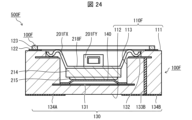
- Fig. 23 is a top view showing an example of a battery module 500F with the lid 160 removed.
- Fig. 24 is a cross-sectional view taken along line XXIV-XXIV in Fig. 23.
- Fig. 25 is a diagram showing a state in which a battery 200F is housed in a battery package 100F.
- the bottom diagram in Fig. 25 is a cross-sectional view taken along line XXV-XXV in Fig. 23.
- the internal structure of the battery 200F is omitted from Figs. 24 and 25.
- the battery module 500F includes a battery package 100F and a battery 200F housed in the first recess 113 of the battery package 100F.
- the battery package 100F includes an insulating substrate 110F.
- the insulating substrate 110F has a limiting portion 150F that protrudes from the inner wall surface of the first recess 113 toward the center of the first recess 113.
- the insulating substrate 110F also has a step portion on the first surface 111.
- the second electrode 132 is located on the upper surface of the step portion.
- the battery 200F has a conductive member 218F located on the upper surface of the positive electrode can 214.
- the conductive member 218F may be, for example, a plate-shaped member (metal plate) having electrical conductivity.
- the conductive member 218F has a first protrusion 201FX and a second protrusion 201FY that protrude from the side surface 214c when viewed from above.
- the first protrusion 201FX may extend above the positive electrode can 214 or diagonally upward.
- the portion protruding from the positive electrode can 214 has multiple curved portions that change direction in the up-down direction.
- the first protrusion 201FX is electrically connected to the second electrode 132. By having multiple curved portions, the first protrusion 201FX has elasticity in the up-down direction, and can stabilize the electrical connection with the second electrode 132.
- the second protrusion 201FY has a through hole 201FP.
- the two first protrusions 201X and the two second protrusions 201Y are alternately positioned at 90° intervals along the circumferential direction of the side surface 214c.
- the battery 200F can be housed and fixed in the battery package 100F by the elastic deformation of the conductive member 218F.
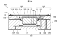
- Fig. 26 is a cross-sectional view showing an example of a battery module 500G with the lid 160 removed. In Fig. 26, the internal structure of the battery 200G is not shown.
- the battery module 500G includes a battery package 100G and a battery 200G housed in the first recess 113 of the battery package 100G.
- the battery 200G has a conductive member 218G on the upper surface of the positive electrode can 214.
- the battery 200G also has a protrusion 201G that extends downward from the conductive member 218G along the side surface 214c of the battery 200G and protrudes upward or diagonally upward.
- the protrusion 201G may be configured to protrude upward or diagonally upward from the side surface 214c of the battery 200G, similar to the protrusion 201A (see FIG. 7).
- the protrusion 201G has a through hole 201GP.
- the insulating substrate 110G of the battery package 100G has a number of limiting portions 150G that protrude from the inner wall surface of the first recess 113 toward the center of the first recess 113.
- the second electrode 132 is located on the underside of the limiting portions 150G.
- the limiting portion 150G engages with the through hole 201GP of the protrusion 201G, thereby enabling electrical connection between the battery 200G and the second electrode 132 located on the underside of the limiting portion 150G.
- the protrusion 201G protrudes upward from the side surface 214c of the battery 200G, and the through hole 201GP of the protrusion 201G engages with the limiting portion 150G on the side of the battery 200G, so that the space S between the battery 200G and the lid 160 can be reduced. This allows the energy density of the battery module 500G to be increased.
- the second electrode 132 may be located on the upper surface of at least one limiting portion 150G and on the inner surface of the insulating substrate 110E above the limiting portion 150G.
- a battery module in aspect 1 of the present disclosure comprises a battery having electrodes on top and bottom and having at least one protrusion; and a package having an insulating substrate having a first surface, a second surface opposite the first surface, and a first recess opening to the first surface and accommodating the battery, a first external electrode located on the second surface, a second external electrode located on the second surface, a first electrode located on a bottom surface of the first recess and electrically connected to the battery and the first external electrode, a second electrode electrically connected to the battery and the second external electrode, an elastic member located on the first electrode and electrically connecting the battery and the first electrode, and a limiting portion that abuts against the protrusion and limits movement of the battery in a direction away from the bottom surface of the first recess due to the elastic force of the elastic member.
- the battery module of aspect 2 of the present disclosure is the battery module of aspect 1 above, in which the second electrode is located in the limiting portion.
- the battery module of aspect 3 of the present disclosure is the battery module of aspect 1 or aspect 2 above, in which the protrusion protrudes to the side of the battery.
- a battery module according to aspect 4 of the present disclosure is a battery module according to aspect 1 or 2 above, in which the protrusion protrudes above the upper surface of the battery.
- a battery module according to aspect 5 of the present disclosure is a battery module according to any one of aspects 1 to 4 above, in which the insulating substrate has a second recess that opens onto the inner side of the first recess, and the insulating substrate located between the second recess and the first surface is the limiting portion.
- a battery module according to aspect 6 of the present disclosure is the battery module according to aspect 5 above, in which the second electrode is located on the inner surface of the second recess.
- a battery module according to aspect 7 of the present disclosure is a battery module according to any one of aspects 1 to 4 above, in which the insulating substrate has a protrusion protruding from the inner surface of the first recess, and the protrusion is the limiting portion.
- the battery module of aspect 8 of the present disclosure is the battery module of aspect 7 above, in which the second electrode is located on the protruding portion.
- a battery module according to aspect 9 of the present disclosure is a battery module according to any one of aspects 1 to 8 above, in which the battery has, as the protrusion, a first protrusion electrically connected to the second electrode and a second protrusion abutting the limiting portion, the package has a frame on the first surface surrounding the recess, and the second electrode is located between the frame and the recess on the first surface.
- a battery module according to aspect 10 of the present disclosure is the battery module according to aspect 9 above, in which the first protrusions and the second protrusions are alternately positioned along the outer periphery of the battery.
- a battery module according to aspect 11 of the present disclosure is a battery module according to any one of aspects 1 to 10 above, in which the elastic member is a metal spring.
- a battery module according to aspect 12 of the present disclosure is the battery module according to aspect 1 above, wherein the package has a locking fitting electrically connected to the first electrode, and the locking fitting has a side plate extending along the inner surface of the recess in a direction from the bottom surface of the recess toward the opening of the recess, and the side plate has a limiting portion.
- a battery module according to aspect 13 of the present disclosure is a battery module according to any one of aspects 1 to 12 above, which includes a lid that covers the recess and is insulated from the battery.
- the battery module of aspect 14 of the present disclosure is a battery module of any one of aspects 1 to 13 above, which includes a frame portion on the first surface that surrounds the first recess.
- a battery module according to aspect 15 of the present disclosure is the battery module according to aspect 14 above, in which the frame portion has a frame-shaped metal film and a metal frame body joined to the frame-shaped metal film.
- the battery module of aspect 16 of the present disclosure is the battery module of aspect 15 above, in which the frame portion has an insulating frame body between the frame-shaped metal film and the first surface.
Landscapes
- Chemical & Material Sciences (AREA)
- Chemical Kinetics & Catalysis (AREA)
- Electrochemistry (AREA)
- General Chemical & Material Sciences (AREA)
- Engineering & Computer Science (AREA)
- Power Engineering (AREA)
- Microelectronics & Electronic Packaging (AREA)
- Battery Mounting, Suspending (AREA)
Priority Applications (2)
| Application Number | Priority Date | Filing Date | Title |
|---|---|---|---|
| CN202480006795.9A CN120548641A (zh) | 2023-01-11 | 2024-01-09 | 电池模块 |
| JP2024570180A JPWO2024150728A1 (https=) | 2023-01-11 | 2024-01-09 |
Applications Claiming Priority (2)
| Application Number | Priority Date | Filing Date | Title |
|---|---|---|---|
| JP2023-002491 | 2023-01-11 | ||
| JP2023002491 | 2023-01-11 |
Publications (1)
| Publication Number | Publication Date |
|---|---|
| WO2024150728A1 true WO2024150728A1 (ja) | 2024-07-18 |
Family
ID=91896924
Family Applications (1)
| Application Number | Title | Priority Date | Filing Date |
|---|---|---|---|
| PCT/JP2024/000119 Ceased WO2024150728A1 (ja) | 2023-01-11 | 2024-01-09 | 電池モジュール |
Country Status (3)
| Country | Link |
|---|---|
| JP (1) | JPWO2024150728A1 (https=) |
| CN (1) | CN120548641A (https=) |
| WO (1) | WO2024150728A1 (https=) |
Citations (6)
| Publication number | Priority date | Publication date | Assignee | Title |
|---|---|---|---|---|
| JPH1116563A (ja) * | 1997-06-26 | 1999-01-22 | S I I Micro Parts:Kk | 端子付き有機電解質電池 |
| JP2002324533A (ja) * | 2001-04-26 | 2002-11-08 | Sii Micro Parts Ltd | 電気化学セルホルダおよび電気化学セル |
| CN2585420Y (zh) * | 2002-12-02 | 2003-11-05 | 技嘉科技股份有限公司 | 电池座改良结构 |
| JP2005340036A (ja) * | 2004-05-28 | 2005-12-08 | Casio Comput Co Ltd | 電池の構造およびその電池によって駆動される装置 |
| CN203850349U (zh) * | 2014-03-05 | 2014-09-24 | 蔡周贤 | 电池座 |
| JP2022103660A (ja) * | 2020-12-28 | 2022-07-08 | 日本電気株式会社 | 電子機器および電子機器の製造方法 |
-
2024
- 2024-01-09 CN CN202480006795.9A patent/CN120548641A/zh active Pending
- 2024-01-09 WO PCT/JP2024/000119 patent/WO2024150728A1/ja not_active Ceased
- 2024-01-09 JP JP2024570180A patent/JPWO2024150728A1/ja active Pending
Patent Citations (6)
| Publication number | Priority date | Publication date | Assignee | Title |
|---|---|---|---|---|
| JPH1116563A (ja) * | 1997-06-26 | 1999-01-22 | S I I Micro Parts:Kk | 端子付き有機電解質電池 |
| JP2002324533A (ja) * | 2001-04-26 | 2002-11-08 | Sii Micro Parts Ltd | 電気化学セルホルダおよび電気化学セル |
| CN2585420Y (zh) * | 2002-12-02 | 2003-11-05 | 技嘉科技股份有限公司 | 电池座改良结构 |
| JP2005340036A (ja) * | 2004-05-28 | 2005-12-08 | Casio Comput Co Ltd | 電池の構造およびその電池によって駆動される装置 |
| CN203850349U (zh) * | 2014-03-05 | 2014-09-24 | 蔡周贤 | 电池座 |
| JP2022103660A (ja) * | 2020-12-28 | 2022-07-08 | 日本電気株式会社 | 電子機器および電子機器の製造方法 |
Also Published As
| Publication number | Publication date |
|---|---|
| JPWO2024150728A1 (https=) | 2024-07-18 |
| CN120548641A (zh) | 2025-08-26 |
Similar Documents
| Publication | Publication Date | Title |
|---|---|---|
| JP7753495B2 (ja) | 電池用パッケージおよび電池モジュール | |
| CN101573807B (zh) | 具有优良的可生产性和结构稳定性的电池组 | |
| KR100773198B1 (ko) | 표면 실장형 커패시터 및 그 제조방법 | |
| EP1705732B1 (en) | Lithium secondary battery | |
| JP3756096B2 (ja) | 密閉型電池 | |
| CN100440586C (zh) | 无焊接触点型二次电池 | |
| CN101399326A (zh) | 电池组 | |
| JP6967932B2 (ja) | ブレーカー及びそれを備えた安全回路。 | |
| CN101436681A (zh) | 电池组 | |
| US20200321176A1 (en) | Breaker and safety circuit equipped with the same | |
| JP7753560B2 (ja) | 電池用パッケージおよび電池モジュール | |
| CN103858255A (zh) | 二次电池组 | |
| JP7785965B2 (ja) | 電池用パッケージおよび電池モジュール | |
| JPWO2024070787A5 (https=) | ||
| WO2024128281A1 (ja) | 電池用パッケージ、電池モジュール、および電池モジュールの封止方法 | |
| US12080918B2 (en) | Secondary battery and secondary battery assembly | |
| WO2024150728A1 (ja) | 電池モジュール | |
| TWI261274B (en) | Battery cell for surface packaging | |
| JP4951814B2 (ja) | 扁平型二次電池及び電池モジュール | |
| JPWO2024150728A5 (https=) | ||
| WO2025204867A1 (ja) | 電池用パッケージおよび電池モジュール | |
| CN215418513U (zh) | 单电池 | |
| JP7789094B2 (ja) | 電池用パッケージおよび電池モジュール | |
| JPWO2019064777A1 (ja) | 電流遮断装置及び蓄電装置 |
Legal Events
| Date | Code | Title | Description |
|---|---|---|---|
| 121 | Ep: the epo has been informed by wipo that ep was designated in this application |
Ref document number: 24741501 Country of ref document: EP Kind code of ref document: A1 |
|
| ENP | Entry into the national phase |
Ref document number: 2024570180 Country of ref document: JP Kind code of ref document: A |
|
| WWE | Wipo information: entry into national phase |
Ref document number: 2024570180 Country of ref document: JP |
|
| WWE | Wipo information: entry into national phase |
Ref document number: 202480006795.9 Country of ref document: CN |
|
| NENP | Non-entry into the national phase |
Ref country code: DE |
|
| WWP | Wipo information: published in national office |
Ref document number: 202480006795.9 Country of ref document: CN |
|
| 122 | Ep: pct application non-entry in european phase |
Ref document number: 24741501 Country of ref document: EP Kind code of ref document: A1 |