WO2024150403A1 - 消費電力算出装置 - Google Patents
消費電力算出装置 Download PDFInfo
- Publication number
- WO2024150403A1 WO2024150403A1 PCT/JP2023/000749 JP2023000749W WO2024150403A1 WO 2024150403 A1 WO2024150403 A1 WO 2024150403A1 JP 2023000749 W JP2023000749 W JP 2023000749W WO 2024150403 A1 WO2024150403 A1 WO 2024150403A1
- Authority
- WO
- WIPO (PCT)
- Prior art keywords
- power consumption
- motors
- torque
- machine tool
- consumption calculation
- Prior art date
- Legal status (The legal status is an assumption and is not a legal conclusion. Google has not performed a legal analysis and makes no representation as to the accuracy of the status listed.)
- Ceased
Links
Images





Classifications
-
- G—PHYSICS
- G05—CONTROLLING; REGULATING
- G05B—CONTROL OR REGULATING SYSTEMS IN GENERAL; FUNCTIONAL ELEMENTS OF SUCH SYSTEMS; MONITORING OR TESTING ARRANGEMENTS FOR SUCH SYSTEMS OR ELEMENTS
- G05B19/00—Program-control systems
- G05B19/02—Program-control systems electric
- G05B19/18—Numerical control [NC], i.e. automatically operating machines, in particular machine tools, e.g. in a manufacturing environment, so as to execute positioning, movement or co-ordinated operations by means of program data in numerical form
- G05B19/406—Numerical control [NC], i.e. automatically operating machines, in particular machine tools, e.g. in a manufacturing environment, so as to execute positioning, movement or co-ordinated operations by means of program data in numerical form characterised by monitoring or safety
- G05B19/4069—Simulating machining process on screen
Definitions
- This disclosure relates to a power consumption calculation device.
- One aspect of the present disclosure is a power consumption calculation device that includes a machining program acquisition unit that acquires a machining program for a machine tool equipped with a drive unit including at least a spindle or a feed axis, a machine specification acquisition unit that acquires machine specifications of the machine tool, a motor efficiency acquisition unit that acquires motor efficiency of one or more motors in the drive unit, a dynamic simulation unit that simulates time series data of the angular velocity of each of the motors and the torque of each of the motors based on the machining program and the machine specifications, and a power consumption calculation unit that calculates time series data of power consumption consumed by the drive unit based on the time series data of the angular velocity of each of the motors and the torque of each of the motors, and the motor efficiency of each of the motors.
- FIG. 1 is a functional block diagram of a power consumption calculation device according to an embodiment of the present invention.
- 2 is a functional block diagram relating to functions for calculating power consumption in the power consumption calculation device according to the present embodiment.
- FIG. FIG. 1 is a diagram illustrating an example of a machine tool according to an embodiment of the present invention.
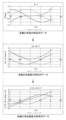
- FIG. 11 is a diagram showing an example of time-series data of angles, angular velocities, and angular accelerations of each axis.
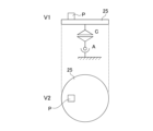
- FIG. 4 is a diagram for explaining torque during acceleration.
- FIG. 4 is a diagram for explaining torque during acceleration.
- FIG. 13 is a diagram for explaining torque due to gravity.
- FIG. 13 is a diagram for explaining torque due to gravity.
- FIG. 11A and 11B are diagrams for explaining torque caused by interference force; 11A and 11B are diagrams for explaining torque caused by interference force; FIG. 2 is a diagram showing an example of machine specifications of a machine tool.
- FIG. 2 is a diagram showing an example of machine specifications of a machine tool.
- FIG. 2 is a diagram showing an example of machine specifications of a machine tool.
- FIG. 2 is a diagram showing an example of machine specifications of a machine tool.
- the control unit 2 is a processor such as a CPU (Central Processing Unit), and realizes various functions by executing programs stored in the memory unit 3.
- CPU Central Processing Unit
- the memory unit 3 is a storage device such as a ROM (Read Only Memory) or RAM (Random Access Memory) that stores the OS (Operating System) and application programs, as well as a hard disk drive or SSD (Solid State Drive) that stores various other information.
- ROM Read Only Memory
- RAM Random Access Memory
- OS Operating System
- SSD Solid State Drive
- the power consumption calculation device 1 When the power consumption calculation device 1 is a computer device independent of the numerical control device, the power consumption calculation device 1 includes a communication unit 4 for wired or wireless communication with the machine tool or numerical control device via a network.
- the communication unit 4 includes a processor, connector, electric circuit, etc. for executing communication.
- the communication unit 4 performs a predetermined process on the communication signal received from the machine tool or numerical control device to acquire data, and inputs the acquired data to the control unit 2.
- the communication unit 4 also performs a predetermined process on the data input from the control unit 2 to generate a communication signal, and transmits the generated communication signal to the machine tool or numerical control device.
- the power consumption calculation device 1 may also acquire machine specifications, which will be described later, from an external storage medium, etc., without being connected to the machine tool or numerical control device by the communication unit 4.
- the input unit 5 is an input interface such as a mouse, keyboard, touch panel, etc.
- the display unit 6 is a device that displays images.
- the display unit 6 is, for example, an LCD (Liquid Crystal Display) or an organic EL (Electroluminescence) display.
- FIG. 2 is a functional block diagram related to functions for calculating power consumption in the power consumption calculation device 1 according to this embodiment.
- the power consumption calculation device 1 includes a processing program acquisition unit 11, a machine specification acquisition unit 12, a motor efficiency acquisition unit 13, a dynamic simulation unit 14, a power consumption calculation unit 15, and a display unit 6.
- the machining program acquisition unit 11 acquires a machining program for a machine tool equipped with a drive unit including at least a spindle or a feed axis. For example, if the power consumption calculation device 1 is incorporated in a numerical control device, the machining program acquisition unit 11 acquires the machining program from a storage device of the numerical control device. If the power consumption calculation device 1 is a computer device independent of the numerical control device, the machining program acquisition unit 11 may acquire a machining program input by the input unit 5, or may acquire the machining program from the machine tool or numerical control device via the communication unit 4. The machining program acquisition unit 11 may also acquire the machining program from an external storage medium, etc.
- the machine specification acquisition unit 12 acquires the machine specifications of the machine tool. For example, if the power consumption calculation device 1 is incorporated in a numerical control device, the machine specification acquisition unit 12 acquires the machine specifications from a storage device of the numerical control device. If the power consumption calculation device 1 is a computer device independent of the numerical control device, the machine specification acquisition unit 12 may acquire the machine specifications input by the input unit 5, or may acquire the machine specifications from the machine tool or numerical control device via the communication unit 4. The machine specification acquisition unit 12 may also acquire the machine specifications of the machine tool from an external storage medium, etc.
- the motor efficiency acquisition unit 13 acquires the motor efficiency of one or more motors in the drive device of the machine tool. For example, if the power consumption calculation device 1 is incorporated in a numerical control device, the motor efficiency acquisition unit 13 acquires the motor efficiency from a storage device of the numerical control device. If the power consumption calculation device 1 is a computer device independent of the numerical control device, the motor efficiency acquisition unit 13 may acquire the motor efficiency input by the input unit 5, or may acquire the motor efficiency from the machine tool or numerical control device via the communication unit 4. The motor efficiency acquisition unit 13 may also acquire the motor efficiency from an external storage medium, etc.
- the dynamics simulation unit 14 simulates the time series data of the angular velocity of each motor and the torque of each motor based on the acquired machining program and the mechanical specifications of the machine tool. Specifically, the dynamics simulation unit 14 acquires angle information of all axes of the machine tool from the machining program, and dynamically simulates the time series data of the angular velocity of each motor and the torque of each motor based on the angle information of all axes and the mechanical specifications of the machine tool.
- the power consumption calculation unit 15 calculates time series data of the power consumption consumed by the drive device of the machine tool based on the time series data of the angular velocity of each motor and the torque of each motor, and the motor efficiency of each motor.
- the display unit 6 displays the power consumption calculated by the power consumption calculation unit 15.
- the torque of each motor includes at least a torque due to gravity and a torque due to interference force, and that the torque of each motor includes a torque due to gravity, a torque due to interference force, a torque during acceleration/deceleration, a torque due to friction, and a torque during cutting.
- the machine specifications of the machine tool also include at least one of the configuration of the machine tool's axes, the friction coefficient of each motor, the moment of inertia of each motor, the eccentric load of each motor, and the work load of each motor.
- FIG. 3 is a diagram showing an example of a machine tool 20 according to this embodiment.
- the machine tool 20 is a 5-axis (CA/XYZ) machining center with a swivel table.
- the machine tool 20 is a 5-axis (CA/XYZ) machining center with a swivel table as shown below, but may be a machining center of another type and with another number of axes.
- the machine tool 20 includes a first horizontal linear motion mechanism 21, a second horizontal linear motion mechanism 22, a vertical linear motion mechanism 23, a first rotation mechanism 24, a table 25, a second rotation mechanism 26, a spindle 27, and a tool 28.
- the first horizontal linear motion mechanism 21 comprises a first base installed on the floor surface and a first slider supported so as to be movable in the X direction (horizontal direction) relative to the first base.
- the second horizontal linear motion mechanism 22 comprises a second base fixed to the first slider and a second slider supported so as to be movable in the Y direction (horizontal direction) relative to the second base.
- the vertical linear motion mechanism 23 comprises a third base fixed to the second slider, and a third slider supported so as to be movable in the Z direction (vertical direction) relative to the third base.
- a spindle 27 to which a tool 28 can be attached is fixed to the third slider.
- the machine tool 20 also comprises a table 25 on which a workpiece is mounted, a first rotation mechanism 24 that rotates the table 25 about a vertical axis, and a second rotation mechanism 26 that tilts the table 25 about a horizontal axis.
- the numerical control device creates speed commands based on the machining program and controls the spindle via the spindle servo control device.
- the numerical control device also creates position commands for the feed axis based on the machining program and controls the feed axis via the feed axis servo control device.
- the spindle 27 includes a spindle motor, and is rotated by the spindle motor driven based on a drive current from a spindle servo control device to rotate the tool 28.
- the feed axes are rotated by the feed axis motor driven based on a drive current from a feed axis servo control device to move the tool 28 or the workpiece.
- FIG. 4 is a diagram showing an example of time series data of the angle, angular velocity, and angular acceleration of the motors that drive each axis.
- the time series data shown in FIG. 4 is time series data of the angle, angular velocity, and angular acceleration of the motors that drive the X-axis, Y-axis, and Z-axis of the machine tool 20 shown in FIG. 3.
- the horizontal axis of the time series data for angles is time t [s] and the vertical axis is angle ⁇ [deg].
- the horizontal axis of the time series data for angular velocity is time t [s] and the vertical axis is angular velocity d ⁇ /dt [deg/s].
- the horizontal axis of the time series data for angular acceleration is time t [s] and the vertical axis is angular acceleration d 2 ⁇ /dt 2 [deg/s 2 ].
- the torque during acceleration/deceleration, torque due to friction, torque due to gravity, torque due to interference force, and torque during cutting are represented by the following generalized functions.
- the torque of each axis is represented by a function that uses the angle ⁇ , angular velocity d ⁇ /dt, and each acceleration d2 ⁇ / dt2 of all axes as input. Note that 1, 2, ..., m are numbers corresponding to each axis. Also, each of the following functions does not necessarily need to use all of the angle ⁇ , angular velocity d ⁇ /dt, and each acceleration d2 ⁇ / dt2 .
- the power consumption P n in each motor is It can be expressed as.
- the angular velocity of the motor can be calculated from time-series data of the motor angle obtained from the machining program, and the motor efficiency can be obtained in advance as a value having the motor torque and angular velocity as variables.
- FIGS 5A and 5B are diagrams for explaining torque during acceleration. Note that viewpoints V1 and V2 shown in Figures 5A, 5B, 6A, 6B, 7A, and 7B correspond to viewpoints V1 and V2 shown in Figure 3.
- machine tool 20 as shown in Figures 5A and 5B, it is assumed that there is an eccentric load (mass point) P on table 25 with mass m, distance r from axis C, and center of gravity at the same height as axis A.
- FIG. 6A and 6B are diagrams for explaining torque due to gravity.
- the torque for supporting axis A against gravity is expressed as follows using the mass M of table 25 obtained in advance and the distance r between the center of gravity of table 25 and the center of rotation of axis A.
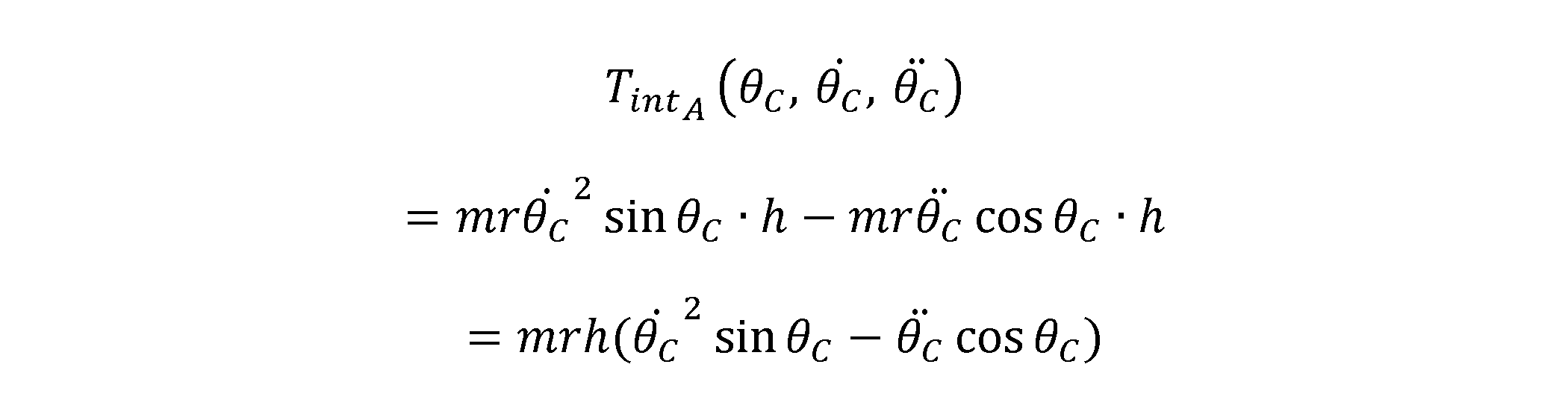
- FIG. 7A and 7B are diagrams for explaining torque due to interference force.
- the machine tool 20 as shown in FIG. 7A and FIG. 7B, it is assumed that there is an eccentric load (mass point) P on the table 25, with mass m and distance r from the axis C. It is assumed that the distance between the eccentric load (mass point) P and a plane parallel to the table 25 including the axis A is h.
- the torque applied during cutting is determined by the tool, the material of the workpiece, and the relative speed during cutting, and is therefore given in advance by an arbitrary function.
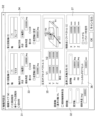
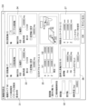
- FIGS. 8 to 11 are diagrams showing examples of machine specifications of the machine tool 20.
- Screens D1 to D4 shown in FIG. 8 to FIG. 11 respectively show examples of input screens for inputting the machine specifications of the machine tool 20.
- screens D1 to D3 allow the input of the machine type 31, linear axis (basic axis) 32, first rotation axis 33, second rotation axis 34, cross offset vector 35, reference tool axis direction 36, and control point shift vector 37 as machine specifications for the machine tool 20.
- screen D4 allows input of the friction coefficient of each axis and moment of inertia of each axis 38, three-dimensional coordinates and weight indicating the position of the center of gravity of the eccentric load 39, and three-dimensional coordinates and weight indicating the position of the center of gravity of the workpiece 40, as machine specifications of the machine tool 20.
- the power consumption calculation device 1 includes a machining program acquisition unit 11 that acquires a machining program for a machine tool equipped with a drive unit including at least a spindle or a feed axis, a machine specification acquisition unit 12 that acquires the machine specifications of the machine tool, a motor efficiency acquisition unit 13 that acquires the motor efficiency of one or more motors in the drive unit of the machine tool, a dynamics simulation unit 14 that simulates time series data of the angular velocity of each motor and the torque of each motor based on the machining program and the machine specifications of the machine tool, and a power consumption calculation unit 15 that calculates time series data of power consumption consumed by the drive unit of the machine tool based on the time series data of the angular velocity of each motor and the torque of each motor, and the motor efficiency of each motor.
- a machining program acquisition unit 11 that acquires a machining program for a machine tool equipped with a drive unit including at least a spindle or a feed axis
- a machine specification acquisition unit 12 that acquires the machine
- the power consumption calculation device 1 can calculate gravity and the inertial forces generated between the axes, which change according to the attitude of the machine tool, based on the axis configuration of the machine tool and information on the eccentric load of the rotating axis, making it possible to perform highly accurate simulations even for machine tools with complex axis configurations. Therefore, the power consumption calculation device 1 can simulate power consumption with high accuracy from the machining program without actually operating the machine tool, and can also be useful in designing machine tools with reduced power consumption.
- the power consumption calculation device 1 also includes a display unit 6 that displays the power consumption calculated by the power consumption calculation unit 15. With this configuration, the power consumption calculation device 1 can present the calculated power consumption to the user.
- the torque of each motor includes at least the torque due to gravity and the torque due to interference forces, and it is preferable that the torque of each motor includes the torque due to gravity, the torque due to interference forces, the torque during acceleration/deceleration, the torque due to friction, and the torque during cutting. Since the torque due to gravity and the torque due to interference forces change depending on the attitude of the machine tool, the power consumption calculation device 1 can simulate the power consumption of the machine tool with high accuracy by calculating the torque of each axis taking into account the attitude of the machine tool including all axes.
- the machine specifications of the machine tool also include at least one of the axis configuration of the machine tool, the friction coefficient of each motor, the moment of inertia of each motor, the eccentric load of each motor, and the load of the workpiece on each motor.
- the power consumption calculation device 1 can calculate the gravity and the inertial force generated between the axes that change according to the attitude of the machine tool based on information on the axis configuration of the machine tool and the eccentric load of the rotating axes, making it possible to simulate power consumption with high accuracy even for machine tools with complex axis configurations.
- the power consumption calculation device 1 can be realized by hardware, software, or a combination of these.
- the control method performed by the power consumption calculation device 1 can also be realized by hardware, software, or a combination of these.
- being realized by software means being realized by a computer reading and executing a program.
- Non-transitory computer readable media include various types of tangible storage media.
- Examples of non-transitory computer readable media include magnetic recording media (e.g., hard disk drives), magneto-optical recording media (e.g., magneto-optical disks), CD-ROMs (Read Only Memory), CD-Rs, CD-R/Ws, and semiconductor memories (e.g., mask ROMs, PROMs (Programmable ROMs), EPROMs (Erasable PROMs), flash ROMs, and RAMs (random access memory)).
- the power consumption calculation device further comprising a power consumption display unit (6) that displays the calculated power consumption.
- a power consumption display unit (6) that displays the calculated power consumption.
- the power consumption calculation device includes at least a torque due to gravity and a torque due to an interference force.
- the power consumption calculation device includes a torque due to gravity, a torque due to the interference force, a torque during acceleration/deceleration, a torque due to friction, and a torque during cutting. (Appendix 5) 3.
Landscapes
- Engineering & Computer Science (AREA)
- Human Computer Interaction (AREA)
- Manufacturing & Machinery (AREA)
- Physics & Mathematics (AREA)
- General Physics & Mathematics (AREA)
- Automation & Control Theory (AREA)
- Numerical Control (AREA)
- Machine Tool Sensing Apparatuses (AREA)
Abstract
Description







モータの角速度は、加工プログラムから得られるモータ角度の時系列データから計算でき、モータ効率は、モータのトルク及び角速度を変数にもつ値として事前に得ることができる。
図5A及び図5Bは、加速時のトルクについて説明するための図である。なお、図5A、図5B、図6A、図6B、図7A及び図7Bに示される視点V1及び視点V2は、図3に示される視点V1及び視点V2に対応する。図5A及び図5Bに示されるような工作機械20において、テーブル25上に質量m、軸Cからの距離がrであり、重心が軸Aと同じ高さの偏心荷重(質点)Pがあると仮定する。

図3に示されるような工作機械20において、軸Xを稼働する際の摩擦によるトルクは、予め得られる摩擦係数μXを用いて以下のように表される。

図6A及び図6Bは、重力によるトルクについて説明するための図である。図6A及び図6Bに示されるような工作機械20において、テーブル25が水平の状態を基準に、第2回転機構26(軸A)がθA回転したとき、重力に対して軸Aを支えるためのトルクは、予め得られるテーブル25の質量M、及びテーブル25の重心と軸Aの回転中心との距離rを用いて以下のように表される。

図7A及び図7Bは、干渉力によるトルクについて説明するための図である。図7A及び図7Bに示されるような工作機械20において、テーブル25上に質量m、軸Cからの距離がrである偏心荷重(質点)Pがあると仮定する。軸Aを含むテーブル25と平行な面と偏心荷重(質点)Pの距離はhと仮定する。偏心荷重Pが軸Aを含むテーブル25と垂直な面上にあり、視点V1から見たときにテーブル25の奥側に存在する状態を基準として、第1回転機構24(軸C)がθC回転した位置にある状態で、軸Cを加速させると、遠心力F2及び慣性力F1が回転軸Aに影響を与える。この力に対抗するためのトルクを

切削時にかかるトルクは、工具、加工対象の材質、及び加工時の相対速度によって決定されるため、予め任意の関数によって与えられる。
(付記1)
少なくとも主軸又は送り軸を含む駆動装置を備える工作機械のための加工プログラムを取得する加工プログラム取得部(11)と、
前記工作機械の機械仕様を取得する機械仕様取得部(12)と、
前記駆動装置における1以上のモータのモータ効率を取得するモータ効率取得部(13)と、
前記加工プログラム及び前記機械仕様に基づいて、前記各モータの角速度及び前記各モータのトルクの時系列データをシミュレーションする力学シミュレーション部(14)と、
前記各モータの角速度及び前記各モータのトルクの時系列データ、並びに前記各モータのモータ効率に基づいて前記駆動装置によって消費される消費電力の時系列データを算出する消費電力算出部(15)と、
を備える消費電力算出装置(1)。
(付記2)
算出された前記消費電力を表示する消費電力表示部(6)を更に備える付記1に記載の消費電力算出装置。
(付記3)
前記各モータのトルクは、少なくとも重力によるトルク及び干渉力によるトルクを含む、付記1又は2に記載の消費電力算出装置。
(付記4)
前記各モータのトルクは、前記重力によるトルク、前記干渉力によるトルク、加減速時トルク、摩擦によるトルク及び切削時トルクを含む、付記3に記載の消費電力算出装置。
(付記5)
前記工作機械の機械仕様は、前記工作機械の軸の構成、前記各モータの摩擦係数、前記各モータの慣性モーメント、前記各モータの偏心荷重、及び前記各モータのワークの荷重のうちの少なくとも1つを含む、付記1又は2に記載の消費電力算出装置。
2 制御部
3 記憶部
4 通信部
5 入力部
6 表示部
11 加工プログラム取得部
12 機械仕様取得部
13 モータ効率取得部
14 力学シミュレーション部
15 消費電力算出部
Claims (5)
- 少なくとも主軸又は送り軸を含む駆動装置を備える工作機械のための加工プログラムを取得する加工プログラム取得部と、
前記工作機械の機械仕様を取得する機械仕様取得部と、
前記駆動装置における1以上のモータのモータ効率を取得するモータ効率取得部と、
前記加工プログラム及び前記機械仕様に基づいて、前記各モータの角速度及び前記各モータのトルクの時系列データをシミュレーションする力学シミュレーション部と、
前記各モータの角速度及び前記各モータのトルクの時系列データ、並びに前記各モータのモータ効率に基づいて前記駆動装置によって消費される消費電力の時系列データを算出する消費電力算出部と、
を備える消費電力算出装置。 - 算出された前記消費電力を表示する消費電力表示部を更に備える請求項1に記載の消費電力算出装置。
- 前記各モータのトルクは、少なくとも重力によるトルク及び干渉力によるトルクを含む、請求項1又は2に記載の消費電力算出装置。
- 前記各モータのトルクは、前記重力によるトルク、前記干渉力によるトルク、加減速時トルク、摩擦によるトルク及び切削時トルクを含む、請求項3に記載の消費電力算出装置。
- 前記工作機械の機械仕様は、前記工作機械の軸の構成、前記各モータの摩擦係数、前記各モータの慣性モーメント、前記各モータの偏心荷重、及び前記各モータのワークの荷重のうちの少なくとも1つを含む、請求項1又は2に記載の消費電力算出装置。
Priority Applications (4)
| Application Number | Priority Date | Filing Date | Title |
|---|---|---|---|
| PCT/JP2023/000749 WO2024150403A1 (ja) | 2023-01-13 | 2023-01-13 | 消費電力算出装置 |
| JP2024569972A JPWO2024150403A1 (ja) | 2023-01-13 | 2023-01-13 | |
| DE112023004648.4T DE112023004648T5 (de) | 2023-01-13 | 2023-01-13 | Energieverbrauchberechnungsvorrichtung |
| CN202380090538.3A CN120530371A (zh) | 2023-01-13 | 2023-01-13 | 消耗电力计算装置 |
Applications Claiming Priority (1)
| Application Number | Priority Date | Filing Date | Title |
|---|---|---|---|
| PCT/JP2023/000749 WO2024150403A1 (ja) | 2023-01-13 | 2023-01-13 | 消費電力算出装置 |
Publications (1)
| Publication Number | Publication Date |
|---|---|
| WO2024150403A1 true WO2024150403A1 (ja) | 2024-07-18 |
Family
ID=91896644
Family Applications (1)
| Application Number | Title | Priority Date | Filing Date |
|---|---|---|---|
| PCT/JP2023/000749 Ceased WO2024150403A1 (ja) | 2023-01-13 | 2023-01-13 | 消費電力算出装置 |
Country Status (4)
| Country | Link |
|---|---|
| JP (1) | JPWO2024150403A1 (ja) |
| CN (1) | CN120530371A (ja) |
| DE (1) | DE112023004648T5 (ja) |
| WO (1) | WO2024150403A1 (ja) |
Citations (3)
| Publication number | Priority date | Publication date | Assignee | Title |
|---|---|---|---|---|
| JP2011138463A (ja) * | 2010-01-04 | 2011-07-14 | Mitsubishi Electric Corp | 数値制御装置 |
| US20110316335A1 (en) * | 2009-12-17 | 2011-12-29 | Siemens Aktiengesellschaft | Method and device for operating an automation machine |
| JP2014219911A (ja) * | 2013-05-10 | 2014-11-20 | 東芝機械株式会社 | シミュレーション装置およびシミュレーションプログラム |
-
2023
- 2023-01-13 CN CN202380090538.3A patent/CN120530371A/zh active Pending
- 2023-01-13 WO PCT/JP2023/000749 patent/WO2024150403A1/ja not_active Ceased
- 2023-01-13 DE DE112023004648.4T patent/DE112023004648T5/de active Pending
- 2023-01-13 JP JP2024569972A patent/JPWO2024150403A1/ja active Pending
Patent Citations (3)
| Publication number | Priority date | Publication date | Assignee | Title |
|---|---|---|---|---|
| US20110316335A1 (en) * | 2009-12-17 | 2011-12-29 | Siemens Aktiengesellschaft | Method and device for operating an automation machine |
| JP2011138463A (ja) * | 2010-01-04 | 2011-07-14 | Mitsubishi Electric Corp | 数値制御装置 |
| JP2014219911A (ja) * | 2013-05-10 | 2014-11-20 | 東芝機械株式会社 | シミュレーション装置およびシミュレーションプログラム |
Also Published As
| Publication number | Publication date |
|---|---|
| CN120530371A (zh) | 2025-08-22 |
| JPWO2024150403A1 (ja) | 2024-07-18 |
| DE112023004648T5 (de) | 2025-09-04 |
Similar Documents
| Publication | Publication Date | Title |
|---|---|---|
| JP5793200B2 (ja) | 工作機械の切削力検出装置、切削力検出方法、加工異常検出方法、および加工条件制御システム | |
| US9342065B2 (en) | Path interference and generation device and method | |
| JP5804367B2 (ja) | 加工誤差予測方法、加工誤差予測装置、工具経路修正方法及び工具経路修正装置 | |
| JP4847613B2 (ja) | 多軸加工機用数値制御装置 | |
| JP2013515313A (ja) | 数値制御マシンツールのための予測制御及び仮想表示システム | |
| CN109414792A (zh) | 工作机械、加工件的制造方法及加工系统 | |
| JP2014219911A (ja) | シミュレーション装置およびシミュレーションプログラム | |
| JP7558776B2 (ja) | 計算機、パラメータ推定処理方法、及びパラメータ推定処理プログラム | |
| JP2013054431A5 (ja) | ||
| JP6706518B2 (ja) | 加工時間予測装置、切削加工システムおよび加工時間予測方法 | |
| WO2024150403A1 (ja) | 消費電力算出装置 | |
| JP2018128986A (ja) | 経路補正方法及び多軸加工機の制御装置 | |
| JP2016064497A (ja) | データ補正装置、データ補正方法、及び、加工装置 | |
| CN115885225A (zh) | 数值控制系统及干扰检查辅助方法 | |
| JPH0736519A (ja) | ロボットのニアミスチェック方法 | |
| JP2017222028A (ja) | 振動周期を加工面上の長さに変換して表示する波形表示装置 | |
| JP6820100B2 (ja) | 形状測定装置の制御方法 | |
| JP7560294B2 (ja) | 数値制御システム及び干渉チェック方法 | |
| JP7728485B1 (ja) | 加工方法、評価方法、制御装置、プログラムおよび評価用ワーク | |
| JP7817372B2 (ja) | ロボット装置の動作状態を算出するシミュレーション装置 | |
| JP6915182B1 (ja) | 工作機械、工作機械の制御方法、および工作機械の制御プログラム | |
| CN119594857B (zh) | 电机轴径向位移的确定方法、装置和系统 | |
| WO2025057300A1 (ja) | シミュレーション装置およびコンピュータ読み取り可能な記憶媒体 | |
| CN112034783B (zh) | 机床控制装置以及机床 | |
| JP2009116751A (ja) | 多軸制御システムの設計ツール |
Legal Events
| Date | Code | Title | Description |
|---|---|---|---|
| 121 | Ep: the epo has been informed by wipo that ep was designated in this application |
Ref document number: 23916024 Country of ref document: EP Kind code of ref document: A1 |
|
| WWE | Wipo information: entry into national phase |
Ref document number: 2024569972 Country of ref document: JP |
|
| WWE | Wipo information: entry into national phase |
Ref document number: 112023004648 Country of ref document: DE |
|
| WWE | Wipo information: entry into national phase |
Ref document number: 202380090538.3 Country of ref document: CN |
|
| WWP | Wipo information: published in national office |
Ref document number: 202380090538.3 Country of ref document: CN |
|
| WWP | Wipo information: published in national office |
Ref document number: 112023004648 Country of ref document: DE |
|
| 122 | Ep: pct application non-entry in european phase |
Ref document number: 23916024 Country of ref document: EP Kind code of ref document: A1 |