WO2024150321A1 - 永久磁石回転子および永久磁石回転子の製造方法 - Google Patents
永久磁石回転子および永久磁石回転子の製造方法 Download PDFInfo
- Publication number
- WO2024150321A1 WO2024150321A1 PCT/JP2023/000445 JP2023000445W WO2024150321A1 WO 2024150321 A1 WO2024150321 A1 WO 2024150321A1 JP 2023000445 W JP2023000445 W JP 2023000445W WO 2024150321 A1 WO2024150321 A1 WO 2024150321A1
- Authority
- WO
- WIPO (PCT)
- Prior art keywords
- magnet
- mold
- recesses
- permanent magnet
- magnetic
- Prior art date
- Legal status (The legal status is an assumption and is not a legal conclusion. Google has not performed a legal analysis and makes no representation as to the accuracy of the status listed.)
- Ceased
Links
Images


Classifications
-
- H—ELECTRICITY
- H02—GENERATION; CONVERSION OR DISTRIBUTION OF ELECTRIC POWER
- H02K—DYNAMO-ELECTRIC MACHINES
- H02K1/00—Details of the magnetic circuit
- H02K1/06—Details of the magnetic circuit characterised by the shape, form or construction
- H02K1/22—Rotating parts of the magnetic circuit
- H02K1/27—Rotor cores with permanent magnets
- H02K1/2706—Inner rotors
- H02K1/272—Inner rotors the magnetisation axis of the magnets being perpendicular to the rotor axis
- H02K1/274—Inner rotors the magnetisation axis of the magnets being perpendicular to the rotor axis the rotor consisting of two or more circumferentially positioned magnets
- H02K1/2753—Inner rotors the magnetisation axis of the magnets being perpendicular to the rotor axis the rotor consisting of two or more circumferentially positioned magnets the rotor consisting of magnets or groups of magnets arranged with alternating polarity
- H02K1/278—Surface mounted magnets; Inset magnets
Definitions
- This disclosure relates to a permanent magnet rotor and a method for manufacturing a permanent magnet rotor.
- Bonded magnets can be manufactured by injection molding in the same way as general resin materials. For this reason, permanent magnet rotors can be easily manufactured using bonded magnets, and they are widely used, for example, as permanent magnet rotors for air conditioner fan motors. To meet the demands of energy conservation in recent years, there is a strong demand for stronger magnetic force of magnets, and although ferrite bonded magnets are generally used, rare earth bonded magnets are sometimes used. However, rare earth bonded magnets are expensive materials.
- Patent Document 1 uses a two-layer permanent magnet rotor with a ferrite bonded magnet on the inner circumference and a rare earth magnetic bonded magnet on the outer circumference, achieving both performance and cost. Patent Document 1 states that when the outer circumference magnet is molded, the magnetic poles formed on the inner circumference magnet are attracted and fixed in position by the magnetic attraction force generated from the surface of the molding die for the outer circumference magnet.
- Patent Document 1 When forming magnets into a two-layer structure, it is necessary to align the magnetic pole phase of the inner magnet with that of the outer magnet.
- Patent Document 1 when the outer magnet is thick, the accuracy of position fixing by magnetic attraction deteriorates, and the magnetic pole positions of the outer magnet and inner magnet become misaligned, resulting in issues such as a decrease in surface magnetic flux density and distortion of the magnetic flux, which increases the torque ripple of the motor in which it is installed.
- This disclosure has been made in consideration of the above, and aims to obtain a permanent magnet rotor in which the magnetic pole phases of the inner and outer magnets match.
- the permanent magnet rotor of the present disclosure comprises a rotating shaft, an inner magnet which is a cylindrical bonded magnet that holds the rotating shaft, and an outer magnet which is a cylindrical bonded magnet that is provided on the outer periphery of the inner magnet.
- the inner magnet has a plurality of first recesses that are evenly spaced circumferentially at one end in the axial direction.
- the permanent magnet rotor disclosed herein has the effect of providing a permanent magnet rotor in which the magnetic pole phases of the inner and outer magnets match.
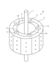
- FIG. 1 is a perspective view showing a configuration of a permanent magnet rotor according to a first embodiment
- FIG. 1 is a cross-sectional view showing a configuration of a permanent magnet rotor according to a first embodiment.
- FIG. 3 is a cross-sectional view showing the configuration of one end of the permanent magnet rotor according to the first embodiment.
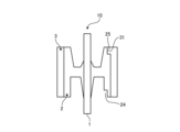
- FIG. 13 is a perspective view showing the configuration of the other end of the permanent magnet rotor according to the first embodiment;
- FIG. 1 is a top view showing the positional relationship between magnetic field-oriented magnetic field lines and weld lines in a permanent magnet rotor according to a first embodiment.
- FIG. 1 is a top view showing the positional relationship between magnetic field-oriented magnetic field lines and weld lines in a permanent magnet rotor according to a first embodiment.
- FIG. 1 is a schematic plan view showing the positional relationship between one end of a permanent magnet rotor of the first embodiment and a second magnetic field orientation mold
- FIG. 2 is a plan view showing the positional relationship of a first recess, a magnetic pole center, and a weld line in a magnet portion of a permanent magnet rotor according to the first embodiment
- FIG. 13 is a schematic plan view showing the positional relationship between the other end of the permanent magnet rotor of the first embodiment and a second magnetic field orientation mold
- FIG. 2 is a plan view showing the positional relationship of the protrusions, the magnetic pole center, and the weld line in the magnet portion of the permanent magnet rotor according to the first embodiment
- FIG. 1 is a schematic diagram showing magnetic flux distribution on an outer peripheral surface of a permanent magnet rotor according to a first embodiment
- FIG. 1 is a process diagram showing a manufacturing process of a permanent magnet rotor in a second embodiment.
- FIG. 13 is a cross-sectional view showing a disassembled state of a first mold used in the manufacturing process of the second embodiment;
- FIG. 11 is a plan view showing a first magnetic field orientation mold of the first mold of the second embodiment;
- FIG. 13 is a cross-sectional view showing a first mold used in the manufacturing process of the second embodiment in an assembled state.
- FIG. 11 is a cross-sectional view showing an inner periphery side magnet manufactured by the first mold of the second embodiment.
- FIG. 13 is a cross-sectional view showing a disassembled state of a second mold used in the manufacturing process of the second embodiment;
- FIG. 13 is a cross-sectional view showing a second mold used in the manufacturing process of the second embodiment in an assembled state.
- FIG. 11 is a cross-sectional view showing an outer magnet manufactured using the second die according to the second embodiment.
- Fig. 1 is a perspective view showing the configuration of permanent magnet rotor 10 according to embodiment 1.
- Fig. 2 is a cross-sectional view showing the configuration of permanent magnet rotor 10 according to embodiment 1.
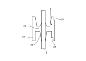
- Fig. 3 is a cross-sectional view showing the configuration of one end of permanent magnet rotor 10 according to embodiment 1.
- Fig. 3 is a cross-sectional view taken along III-III in Fig. 2.
- Fig. 4 is a perspective view showing the configuration of the other end of permanent magnet rotor 10 according to embodiment 1.
- the permanent magnet rotor 10 has a rotating shaft 1, an inner magnet 2, and an outer magnet 3.
- the inner magnet 2 has an inner shaft holding portion 21 that holds the rotating shaft 1, a cylindrical magnetic portion 22 on the outer circumference, and a connection portion 23 that connects the magnetic portion 22 and the shaft holding portion 21.
- a plurality of first recesses 24 are provided on the inner circumference of one axial end of the magnetic portion 22.
- the permanent magnet rotor 10 since the permanent magnet rotor 10 has 10 magnetic poles, five first recesses 24, which is half the number of magnetic poles, are provided and are evenly spaced in the circumferential direction. The number of magnetic poles is the total number of N poles and S poles.
- the five first recesses 24 have the same shape and are provided only at one axial end of the magnetic portion 22.
- a plurality of semicircular second recesses 25 recessed from the outer edge to the inner circumference are provided as shown in FIG. 4.
- five second recesses 25, which is half the number of magnetic poles are provided and are spaced evenly in the circumferential direction.
- a cross section of the second recess 25 cut perpendicularly to the axial direction of the rotating shaft 1 is semicircular.
- the five second recesses 25 are the same shape and are provided only at the other axial end of the magnetic part 22.
- the outer magnet 3 has a cylindrical shape.
- the outer magnet 3 has multiple gate connection parts 4 and multiple semicircular convex parts 31 provided on the inner side of the gate connection parts 4.
- the gate connection parts 4 are connected to the gate, which is the resin inlet of the injection molding machine.
- the semicircular convex parts 31 protruding on the inner side are provided only on the other axial end of the outer magnet 3, i.e., the end on the side where the second recess 25 is formed.
- the multiple semicircular convex parts 31 fit into the multiple semicircular second recesses 25 of the inner magnet 2.
- the inner magnet 2 and the outer magnet 3 are bonded magnets, and are formed by insert injection molding with a magnetic field orientation within the mold.
- the magnetic force portion 22 of the inner magnet 2 and the outer magnet 3 form the magnet portion 11 that functions as a magnet for the permanent magnet rotor 10.
- the magnetic field orientation of the inner magnet 2 and the outer magnet 3 is the same, and the magnetic poles of the inner magnet 2 and the outer magnet 3 are identical.
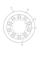
- FIG. 5 is a top view showing the positional relationship between the magnetic field alignment magnetic lines and the weld lines in the permanent magnet rotor 10 of the first embodiment.
- FIG. 5 shows the permanent magnet rotor 10 arranged in a magnetic field alignment mold.
- the magnetic field alignment mold shown in FIG. 5 corresponds to the first magnetic field alignment mold 43 and the second magnetic field alignment mold 53 described below.
- a plurality of teeth 45 of the magnetic field alignment mold are shown around the permanent magnet rotor 10.
- Magnetic field alignment magnets (not shown) are arranged between the teeth 45.
- FIG. 5 shows the concentric magnetic field lines 7 formed in the magnet portion 11 of the permanent magnet rotor 10 by the magnetic field alignment mold.
- the permanent magnet rotor 10 has 10 magnetic poles. Since there are 10 magnetic poles, the magnetic field lines 7 are generated in 10 locations.
- the first recesses 24 are provided at five locations at equal intervals facing the multiple tooth portions 45. In the first embodiment, the first recesses 24 are provided to face five of the 10 tooth portions 45.
- the weld line 6 is located in the middle of the multiple tooth portions 45.
- the inter-pole space 8, which is the middle position between adjacent magnetic poles, is magnetically oriented so that it is in the same position as the weld line 6.
- the magnetic resin material is injected simultaneously from the multiple gate connection portions 4, so that five weld lines 6 are formed in the middle positions of the adjacent gate connection portions 4 in the circumferential direction.
- the outer magnet 3 is insert injection molded on the outer circumference of the inner magnet 2.
- the inner magnet 2 needs to be set in the die in such a way that the phase of the rotational direction matches that of the second magnetic field orientation magnet placed in the second magnetic field orientation die 53 described later in order to magnetically orient the outer magnet 3.
- the first recess 24 provided on the inner circumference of the magnetic part 22 of the inner magnet 2 can be positioned with high precision by being set in alignment with the protrusion 62 provided in the second die 50 (described later) in which the second magnetic field orientation die 53 is placed.
- Figure 6 is a schematic plan view showing the positional relationship between one end of the permanent magnet rotor 10 of embodiment 1 and the second magnetic field orientation mold 53.
- Figure 7 is a plan view showing the positional relationship between the first recess 24, the magnetic pole center 12, and the weld line 6 in the magnet part 11 of the permanent magnet rotor 10 of embodiment 1.
- the second magnetic field orientation mold 53 is a mold for magnetizing the outer magnet 3 by insert resin molding.
- the second magnetic field orientation mold 53 has a cylindrical outer periphery yoke 54, a plurality of teeth 55, and a plurality of magnetic field orientation magnets 56.
- the plurality of teeth 55 extend from the outer periphery yoke 54 toward the inner circumference and are evenly arranged in the circumferential direction.
- the plurality of magnetic field orientation magnets 56 are arranged between adjacent teeth 55.
- the magnetic field orientation magnets 56 are arranged alternately so that the N and S pole directions face the circumferential direction and the N poles and S poles of adjacent magnetic field orientation magnets 56 face each other.
- north and south poles are formed on adjacent tooth portions 55, and a magnetic field is formed from the adjacent tooth portions 55 to the magnet portion 11 in the direction of the magnetic field lines 7 (see Figure 7).
- Each first recess 24 of the inner circumference magnet 2 is positioned opposite the tooth portion 55 of the second magnetic field orientation die 53. That is, due to the magnetic field orientation by the second magnetic field orientation die 53, as shown in FIG. 7, a magnetic pole center 12 is formed in the portion of the magnet part 11 facing each tooth portion 55, and no magnetic pole is formed on the inner circumference side, so that each first recess 24 is positioned at a position where the magnetic force is zero on the inner circumference side of the magnet part 11.
- the magnetic pole center 12 is the central position of the magnetic pole.
- FIG. 8 is a schematic plan view showing the positional relationship between the other end of the permanent magnet rotor 10 of the first embodiment and the second magnetic field orientation mold 53.
- FIG. 9 is a plan view showing the positional relationship between the convex portion 31, the magnetic pole center 12, and the weld line 6 in the magnet portion 11 of the permanent magnet rotor 10 of the first embodiment.
- the outer magnet 3 is insert injection molded so as to fill the second concave portion 25 of the inner magnet 2.
- the convex portion 31 of the outer magnet 3 is fitted into the second concave portion 25 of the inner magnet 2.
- the five protrusions 31 of the outer magnet 3 are positioned midway between adjacent teeth 55 of the second magnetic field orientation die 53. That is, as shown in FIG. 9, magnetic pole centers 12 are formed in the portions of the magnet section 11 that face each tooth 55 due to magnetic field orientation by the second magnetic field orientation die 53, so that each protrusion 31 is positioned midway between adjacent magnetic pole centers 12 in the magnet section 11.
- FIG. 10 is a schematic diagram showing the magnetic flux distribution on the outer peripheral surface of the permanent magnet rotor 10 of the first embodiment.
- the horizontal axis is the angle ⁇
- the vertical axis is the magnetic flux ⁇ .
- a to C are north poles
- C to E are south poles. In the case of 10 poles, if A is 0°, C is 36°, and E is 72°.
- the magnetic flux distribution is sinusoidal.
- A is the boundary position between the south pole and the north pole
- C is the boundary position between the north pole and the south pole.
- B is the position of the maximum magnetic flux of the north pole and the magnetic pole center of the north pole.
- D is the position of the maximum magnetic flux of the south pole and the magnetic pole center of the south pole. As shown in FIG.
- the first recesses 24 are installed at equal intervals at 1/2 the number of magnetic poles of the permanent magnet rotor 10, and are positioned at a position where the magnetic force of the magnetic field orientation of the mold is zero, so that magnetic distortion can be minimized.
- the first recesses 24 are positioned at one end in the axial direction of the inner circumference side magnet 2. By arranging them in this way, positioning is possible when molding the permanent magnet rotor 10 from above and below in the axial direction using an upper mold and a lower mold.
- the first recesses 24 are also formed on the inner surface of the magnetic force portion 22 of the inner circumference side magnet 2. By arranging them in this way, the effect on the magnetic flux of the permanent magnet rotor 10 can be suppressed.
- the number of the first recesses 24 is, for example, 5 when the number of magnetic poles is 10, and 10 when the number of magnetic poles is 20. Alternatively, the number of the first recesses 24 may be 5 when the number of magnetic poles is 20. That is, the number of the first recesses 24 may be 1/(2N) (N is a natural number) of the number of magnetic poles. Furthermore, it is more preferable that the number of the first recesses 24 is a prime number. By making the number of the first recesses 24 a prime number, the mode of the electromagnetic excitation force can be suppressed.
- first recesses 24 when the number of magnetic poles is 20, two-fold rotational symmetry occurs around the entire circumference of the rotation axis, so that an electromagnetic excitation force with twice the frequency is generated for one circumference.
- the number of the first recesses 24 By making the number of the first recesses 24 a prime number, only frequencies corresponding to the entire circumference and the number of the first recesses 24 are generated, so that it is possible to suppress excitation forces of unnecessary frequencies.
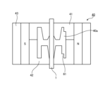
- FIG. 11 is a process diagram showing the manufacturing process of the permanent magnet rotor 10 in the second embodiment.
- FIG. 12 is a cross-sectional view showing a state in which the first mold 40 used in the manufacturing process of the second embodiment is disassembled.
- FIG. 13 is a plan view showing the first magnetic field orientation mold 43 of the first mold 40 of the second embodiment.
- FIG. 14 is a cross-sectional view showing a state in which the first mold 40 used in the manufacturing process of the second embodiment is assembled.
- FIG. 15 is a cross-sectional view showing an inner circumference side magnet 2 manufactured by the first mold 40 of the second embodiment.
- FIG. 16 is a cross-sectional view showing a state in which the second mold 50 used in the manufacturing process of the second embodiment is disassembled.
- FIG. 17 is a cross-sectional view showing a state in which the second mold 50 used in the manufacturing process of the second embodiment is assembled.
- FIG. 18 is a cross-sectional view showing an outer circumference side magnet 3 manufactured by the second mold 50 of the second embodiment.
- the permanent magnet rotor 10 is manufactured by forming an inner magnet 2 around the rotating shaft 1 and forming an outer magnet 3 on the outer circumference of the inner magnet 2.
- the first mold 40 has a first upper mold 41, a first lower mold 42, and a first magnetic field orientation mold 43.
- the central hole of the first upper mold 41 and the central hole of the first lower mold 42 are inserted into the rotating shaft 1 to form a first space 40a surrounded by the first upper mold 41 and the first lower mold 42.
- the first magnetic field orientation mold 43 is disposed on the outer periphery of the first upper mold 41 and the first lower mold 42.
- the first lower mold 42 is provided with a plurality of convex portions 61 for forming a plurality of first recesses 24.
- the first upper mold 41 is provided with a plurality of convex portions 63 for forming a plurality of second recesses 25.
- the first magnetic field orientation mold 43 is a mold for insert-molding the inner magnet 2 with resin and magnetizing it. As shown in FIG. 13, the first magnetic field orientation mold 43 has a cylindrical outer periphery yoke 44, multiple teeth 45, and multiple magnetic field orientation magnets 46.
- the multiple teeth 45 extend from the outer periphery yoke 44 toward the inner circumference and are evenly arranged in the circumferential direction.
- the multiple magnetic field orientation magnets 46 are arranged between adjacent teeth 45.
- the magnetic field orientation magnets 46 are arranged alternately so that the N and S pole directions face the circumferential direction and the N poles and S poles face each other in adjacent magnetic field orientation magnets 46. By arranging the magnetic field orientation magnets 46 in this way, N and S poles are formed in the adjacent teeth 45, and a magnetic field is formed in the direction of the magnetic field lines 7 from the adjacent teeth 45 toward the center.
- Inner circumference magnet forming process (step S2) With a magnetic field formed in the first space 40a, a first magnetic resin material is injection molded from the gate of the first upper die 41.
- the first magnetic resin material is, for example, an anisotropic ferrite bond magnet material.
- the anisotropic magnetic resin material is oriented in the direction of the magnetic field lines 7, and an inner magnet 2 magnetized to correspond to the shape of the first space 40a and the direction of the magnetic field lines 7 formed by the magnetic field alignment magnet 46 is formed around the rotation axis 1.
- a first recess 24 is formed at one end of the inner magnet 2 in the axial direction by the convex portion 61 of the first lower die 42.
- a second recess 25 is formed at the other end of the inner magnet 2 in the axial direction by the convex portion 63 of the first upper die 41.
- the second mold 50 has a second upper mold 51 having a gate, a second lower mold 52 having a convex portion 62 that fits into the first concave portion 24, and a second magnetic field orientation mold 53.
- the center hole of the second upper mold 51 and the center hole of the second lower mold 52 are inserted into the rotating shaft 1 held by the inner circumference side magnet 2 to form a second space 50a surrounded by the second upper mold 51 and the second lower mold 52.
- the second magnetic field orientation mold 53 is disposed on the outer periphery of the second upper mold 51 and the second lower mold 52.
- the second magnetic field orientation mold 53 has the same shape as the first magnetic field orientation mold 43 and the same number of magnetic poles.
- the first concave portion 24 of the inner circumference side magnet 2 and the convex portion 62 provided on the second lower mold 52 of the second mold 50 are positioned in the rotation direction so that the magnetic pole center 12 formed on the inner circumference side magnet 2 coincides with the magnetic pole center 12 formed by the second magnetic field orientation mold 53.
- step S4 With a magnetic field formed in the second space 50a, the second magnetic resin material is injection molded from the multiple gates of the second upper mold 51.
- the second magnetic resin material is, for example, an anisotropic rare earth bonded magnet material.
- the anisotropic magnetic resin material is oriented in the direction of the magnetic field lines 7, and the outer periphery magnet 3 magnetized to correspond to the shape of the second space 50a and the direction of the magnetic field lines 7 formed by the magnetic field orientation magnet 56 is formed on the outer periphery of the inner periphery magnet 2, and the permanent magnet rotor 10 is completed.
- multiple protrusions 31 that fit into the multiple second recesses 25 are formed.
- the first recess 24 of the inner magnet 2 and the protrusion 62 provided on the second lower die 52 of the second die 50 are used to position the magnet in the rotational direction so that the magnetic pole center 12 formed on the inner magnet 2 coincides with the magnetic pole center 12 formed by the second magnetic field orientation die 53.
- the convex portion 62 that fits into the first recess 24 is provided on the second lower mold 52 of the second mold 50, but the convex portion 62 that fits into the first recess 24 may also be provided on the second upper mold 51 of the second mold 50.
Landscapes
- Engineering & Computer Science (AREA)
- Power Engineering (AREA)
- Manufacture Of Motors, Generators (AREA)
- Permanent Field Magnets Of Synchronous Machinery (AREA)
Priority Applications (3)
| Application Number | Priority Date | Filing Date | Title |
|---|---|---|---|
| PCT/JP2023/000445 WO2024150321A1 (ja) | 2023-01-11 | 2023-01-11 | 永久磁石回転子および永久磁石回転子の製造方法 |
| GB2509365.9A GB2640097A (en) | 2023-01-11 | 2023-01-11 | Permanent magnet rotor and method for manufacturing permanent magnet rotor |
| JP2024569902A JPWO2024150321A1 (https=) | 2023-01-11 | 2023-01-11 |
Applications Claiming Priority (1)
| Application Number | Priority Date | Filing Date | Title |
|---|---|---|---|
| PCT/JP2023/000445 WO2024150321A1 (ja) | 2023-01-11 | 2023-01-11 | 永久磁石回転子および永久磁石回転子の製造方法 |
Publications (1)
| Publication Number | Publication Date |
|---|---|
| WO2024150321A1 true WO2024150321A1 (ja) | 2024-07-18 |
Family
ID=91896626
Family Applications (1)
| Application Number | Title | Priority Date | Filing Date |
|---|---|---|---|
| PCT/JP2023/000445 Ceased WO2024150321A1 (ja) | 2023-01-11 | 2023-01-11 | 永久磁石回転子および永久磁石回転子の製造方法 |
Country Status (3)
| Country | Link |
|---|---|
| JP (1) | JPWO2024150321A1 (https=) |
| GB (1) | GB2640097A (https=) |
| WO (1) | WO2024150321A1 (https=) |
Citations (3)
| Publication number | Priority date | Publication date | Assignee | Title |
|---|---|---|---|---|
| WO2016203524A1 (ja) * | 2015-06-15 | 2016-12-22 | 三菱電機株式会社 | 永久磁石電動機 |
| WO2017064767A1 (ja) * | 2015-10-14 | 2017-04-20 | 三菱電機株式会社 | 電動機及び空気調和機 |
| WO2022153441A1 (ja) * | 2021-01-14 | 2022-07-21 | 三菱電機株式会社 | 回転子、電動機、送風機及び空気調和装置 |
-
2023
- 2023-01-11 JP JP2024569902A patent/JPWO2024150321A1/ja active Pending
- 2023-01-11 WO PCT/JP2023/000445 patent/WO2024150321A1/ja not_active Ceased
- 2023-01-11 GB GB2509365.9A patent/GB2640097A/en active Pending
Patent Citations (3)
| Publication number | Priority date | Publication date | Assignee | Title |
|---|---|---|---|---|
| WO2016203524A1 (ja) * | 2015-06-15 | 2016-12-22 | 三菱電機株式会社 | 永久磁石電動機 |
| WO2017064767A1 (ja) * | 2015-10-14 | 2017-04-20 | 三菱電機株式会社 | 電動機及び空気調和機 |
| WO2022153441A1 (ja) * | 2021-01-14 | 2022-07-21 | 三菱電機株式会社 | 回転子、電動機、送風機及び空気調和装置 |
Also Published As
| Publication number | Publication date |
|---|---|
| JPWO2024150321A1 (https=) | 2024-07-18 |
| GB2640097A (en) | 2025-10-08 |
| GB202509365D0 (en) | 2025-07-30 |
Similar Documents
| Publication | Publication Date | Title |
|---|---|---|
| US6177745B1 (en) | Permanent magnet rotor type electric motor | |
| US8035273B2 (en) | Rotor assembly having two core portions each with a reduced back portion | |
| US7649298B2 (en) | Claw teeth type electric rotary machine and manufacturing method for stators | |
| JP5901633B2 (ja) | 電気機械のオーバーモールドによる構築 | |
| US7057322B2 (en) | Rotor for reluctance type rotating machine | |
| US9762097B2 (en) | Rotor and motor | |
| CN102916511A (zh) | 旋转电机 | |
| JP5332082B2 (ja) | モータ | |
| CN114448129A (zh) | 无外磁桥电机转子 | |
| JP6950275B2 (ja) | ロータ及びモータ | |
| JPWO2018025407A1 (ja) | コンシクエントポール型の回転子、電動機および空気調和機 | |
| WO2024150321A1 (ja) | 永久磁石回転子および永久磁石回転子の製造方法 | |
| JP7654795B2 (ja) | ロータおよびモータ | |
| KR100679804B1 (ko) | 모터의 회전자 | |
| JP7638434B2 (ja) | 永久磁石回転子 | |
| JP7654090B2 (ja) | ロータ、モータ、及びロータの製造方法 | |
| CN223451704U (zh) | 用于无刷电机的转子以及包括该转子的无刷电机 | |
| US20240079919A1 (en) | Rotor and rotating electric machine | |
| TWI896763B (zh) | 同步馬達的轉子構造 | |
| JP2010088166A (ja) | アキシャルエアギャップ型電動機 | |
| AU2008245193B2 (en) | Field element | |
| CN112383156B (zh) | 一种外转子电机定子及其电机 | |
| WO2021249248A1 (zh) | 一种电机及其转子 | |
| KR19980033428U (ko) | 교류 서보모터의 로터 | |
| CN120090379A (zh) | 转子组件及具有其的永磁电机 |
Legal Events
| Date | Code | Title | Description |
|---|---|---|---|
| 121 | Ep: the epo has been informed by wipo that ep was designated in this application |
Ref document number: 23915945 Country of ref document: EP Kind code of ref document: A1 |
|
| WWE | Wipo information: entry into national phase |
Ref document number: 2024569902 Country of ref document: JP |
|
| ENP | Entry into the national phase |
Ref document number: 202509365 Country of ref document: GB Kind code of ref document: A Free format text: PCT FILING DATE = 20230111 |
|
| WWE | Wipo information: entry into national phase |
Ref document number: 2509365.9 Country of ref document: GB |
|
| NENP | Non-entry into the national phase |
Ref country code: DE |
|
| WWP | Wipo information: published in national office |
Ref document number: 2509365.9 Country of ref document: GB |
|
| 122 | Ep: pct application non-entry in european phase |
Ref document number: 23915945 Country of ref document: EP Kind code of ref document: A1 |