WO2024147277A1 - メッシュ復号装置、メッシュ復号方法及びプログラム - Google Patents
メッシュ復号装置、メッシュ復号方法及びプログラム Download PDFInfo
- Publication number
- WO2024147277A1 WO2024147277A1 PCT/JP2023/045389 JP2023045389W WO2024147277A1 WO 2024147277 A1 WO2024147277 A1 WO 2024147277A1 JP 2023045389 W JP2023045389 W JP 2023045389W WO 2024147277 A1 WO2024147277 A1 WO 2024147277A1
- Authority
- WO
- WIPO (PCT)
- Prior art keywords
- decoded
- vertex
- motion vector
- unit
- mesh
- Prior art date
- Legal status (The legal status is an assumption and is not a legal conclusion. Google has not performed a legal analysis and makes no representation as to the accuracy of the status listed.)
- Ceased
Links
Images











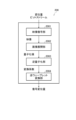
Classifications
-
- H—ELECTRICITY
- H04—ELECTRIC COMMUNICATION TECHNIQUE
- H04N—PICTORIAL COMMUNICATION, e.g. TELEVISION
- H04N19/00—Methods or arrangements for coding, decoding, compressing or decompressing digital video signals
- H04N19/50—Methods or arrangements for coding, decoding, compressing or decompressing digital video signals using predictive coding
- H04N19/597—Methods or arrangements for coding, decoding, compressing or decompressing digital video signals using predictive coding specially adapted for multi-view video sequence encoding
-
- G—PHYSICS
- G06—COMPUTING OR CALCULATING; COUNTING
- G06T—IMAGE DATA PROCESSING OR GENERATION, IN GENERAL
- G06T9/00—Image coding
- G06T9/001—Model-based coding, e.g. wire frame
-
- G—PHYSICS
- G06—COMPUTING OR CALCULATING; COUNTING
- G06T—IMAGE DATA PROCESSING OR GENERATION, IN GENERAL
- G06T9/00—Image coding
- G06T9/004—Predictors, e.g. intraframe, interframe coding
-
- H—ELECTRICITY
- H04—ELECTRIC COMMUNICATION TECHNIQUE
- H04N—PICTORIAL COMMUNICATION, e.g. TELEVISION
- H04N19/00—Methods or arrangements for coding, decoding, compressing or decompressing digital video signals
- H04N19/10—Methods or arrangements for coding, decoding, compressing or decompressing digital video signals using adaptive coding
- H04N19/102—Methods or arrangements for coding, decoding, compressing or decompressing digital video signals using adaptive coding characterised by the element, parameter or selection affected or controlled by the adaptive coding
- H04N19/103—Selection of coding mode or of prediction mode
- H04N19/109—Selection of coding mode or of prediction mode among a plurality of temporal predictive coding modes
-
- H—ELECTRICITY
- H04—ELECTRIC COMMUNICATION TECHNIQUE
- H04N—PICTORIAL COMMUNICATION, e.g. TELEVISION
- H04N19/00—Methods or arrangements for coding, decoding, compressing or decompressing digital video signals
- H04N19/10—Methods or arrangements for coding, decoding, compressing or decompressing digital video signals using adaptive coding
- H04N19/102—Methods or arrangements for coding, decoding, compressing or decompressing digital video signals using adaptive coding characterised by the element, parameter or selection affected or controlled by the adaptive coding
- H04N19/13—Adaptive entropy coding, e.g. adaptive variable length coding [AVLC] or context adaptive binary arithmetic coding [CABAC]
-
- H—ELECTRICITY
- H04—ELECTRIC COMMUNICATION TECHNIQUE
- H04N—PICTORIAL COMMUNICATION, e.g. TELEVISION
- H04N19/00—Methods or arrangements for coding, decoding, compressing or decompressing digital video signals
- H04N19/10—Methods or arrangements for coding, decoding, compressing or decompressing digital video signals using adaptive coding
- H04N19/134—Methods or arrangements for coding, decoding, compressing or decompressing digital video signals using adaptive coding characterised by the element, parameter or criterion affecting or controlling the adaptive coding
- H04N19/136—Incoming video signal characteristics or properties
- H04N19/137—Motion inside a coding unit, e.g. average field, frame or block difference
- H04N19/139—Analysis of motion vectors, e.g. their magnitude, direction, variance or reliability
-
- H—ELECTRICITY
- H04—ELECTRIC COMMUNICATION TECHNIQUE
- H04N—PICTORIAL COMMUNICATION, e.g. TELEVISION
- H04N19/00—Methods or arrangements for coding, decoding, compressing or decompressing digital video signals
- H04N19/10—Methods or arrangements for coding, decoding, compressing or decompressing digital video signals using adaptive coding
- H04N19/169—Methods or arrangements for coding, decoding, compressing or decompressing digital video signals using adaptive coding characterised by the coding unit, i.e. the structural portion or semantic portion of the video signal being the object or the subject of the adaptive coding
- H04N19/17—Methods or arrangements for coding, decoding, compressing or decompressing digital video signals using adaptive coding characterised by the coding unit, i.e. the structural portion or semantic portion of the video signal being the object or the subject of the adaptive coding the unit being an image region, e.g. an object
- H04N19/172—Methods or arrangements for coding, decoding, compressing or decompressing digital video signals using adaptive coding characterised by the coding unit, i.e. the structural portion or semantic portion of the video signal being the object or the subject of the adaptive coding the unit being an image region, e.g. an object the region being a picture, frame or field
-
- H—ELECTRICITY
- H04—ELECTRIC COMMUNICATION TECHNIQUE
- H04N—PICTORIAL COMMUNICATION, e.g. TELEVISION
- H04N19/00—Methods or arrangements for coding, decoding, compressing or decompressing digital video signals
- H04N19/10—Methods or arrangements for coding, decoding, compressing or decompressing digital video signals using adaptive coding
- H04N19/169—Methods or arrangements for coding, decoding, compressing or decompressing digital video signals using adaptive coding characterised by the coding unit, i.e. the structural portion or semantic portion of the video signal being the object or the subject of the adaptive coding
- H04N19/184—Methods or arrangements for coding, decoding, compressing or decompressing digital video signals using adaptive coding characterised by the coding unit, i.e. the structural portion or semantic portion of the video signal being the object or the subject of the adaptive coding the unit being bits, e.g. of the compressed video stream
-
- H—ELECTRICITY
- H04—ELECTRIC COMMUNICATION TECHNIQUE
- H04N—PICTORIAL COMMUNICATION, e.g. TELEVISION
- H04N19/00—Methods or arrangements for coding, decoding, compressing or decompressing digital video signals
- H04N19/50—Methods or arrangements for coding, decoding, compressing or decompressing digital video signals using predictive coding
- H04N19/503—Methods or arrangements for coding, decoding, compressing or decompressing digital video signals using predictive coding involving temporal prediction
- H04N19/51—Motion estimation or motion compensation
- H04N19/513—Processing of motion vectors
-
- H—ELECTRICITY
- H04—ELECTRIC COMMUNICATION TECHNIQUE
- H04N—PICTORIAL COMMUNICATION, e.g. TELEVISION
- H04N19/00—Methods or arrangements for coding, decoding, compressing or decompressing digital video signals
- H04N19/50—Methods or arrangements for coding, decoding, compressing or decompressing digital video signals using predictive coding
- H04N19/503—Methods or arrangements for coding, decoding, compressing or decompressing digital video signals using predictive coding involving temporal prediction
- H04N19/51—Motion estimation or motion compensation
- H04N19/513—Processing of motion vectors
- H04N19/517—Processing of motion vectors by encoding
- H04N19/52—Processing of motion vectors by encoding by predictive encoding
-
- H—ELECTRICITY
- H04—ELECTRIC COMMUNICATION TECHNIQUE
- H04N—PICTORIAL COMMUNICATION, e.g. TELEVISION
- H04N19/00—Methods or arrangements for coding, decoding, compressing or decompressing digital video signals
- H04N19/50—Methods or arrangements for coding, decoding, compressing or decompressing digital video signals using predictive coding
- H04N19/503—Methods or arrangements for coding, decoding, compressing or decompressing digital video signals using predictive coding involving temporal prediction
- H04N19/51—Motion estimation or motion compensation
- H04N19/537—Motion estimation other than block-based
- H04N19/54—Motion estimation other than block-based using feature points or meshes
-
- H—ELECTRICITY
- H04—ELECTRIC COMMUNICATION TECHNIQUE
- H04N—PICTORIAL COMMUNICATION, e.g. TELEVISION
- H04N19/00—Methods or arrangements for coding, decoding, compressing or decompressing digital video signals
- H04N19/70—Methods or arrangements for coding, decoding, compressing or decompressing digital video signals characterised by syntax aspects related to video coding, e.g. related to compression standards
-
- H—ELECTRICITY
- H04—ELECTRIC COMMUNICATION TECHNIQUE
- H04N—PICTORIAL COMMUNICATION, e.g. TELEVISION
- H04N19/00—Methods or arrangements for coding, decoding, compressing or decompressing digital video signals
- H04N19/90—Methods or arrangements for coding, decoding, compressing or decompressing digital video signals using coding techniques not provided for in groups H04N19/10-H04N19/85, e.g. fractals
- H04N19/91—Entropy coding, e.g. variable length coding [VLC] or arithmetic coding
Definitions
- Non-Patent Document 1 discloses a technique for encoding meshes using Non-Patent Document 2.
- the present invention has been made in consideration of the above-mentioned problems, and aims to provide a mesh decoding device, a mesh decoding method, and a program that can improve the coding efficiency of meshes.
- the first feature of the present invention is a mesh decoding device comprising: a motion vector residual decoding unit that generates a motion vector residual and a motion vector prediction mode from an interframe bit stream; a motion vector prediction unit that calculates a predicted value of the motion vector of the vertex to be decoded by a prediction method specified by the prediction mode from among a plurality of prediction methods using the motion vectors of decoded vertices around the vertex to be decoded, the motion vectors of vertices in a reference frame corresponding to the vertex to be decoded, and the motion vectors of vertices in the reference frame corresponding to the decoded vertices around the vertex to be decoded; and a motion vector calculation unit that adds the predicted value of the motion vector and the motion vector residual.
- the second feature of the present invention is a mesh decoding method comprising the steps of: generating a motion vector residual and a motion vector prediction mode from an interframe bit stream; calculating a predicted value of the motion vector of the vertex to be decoded by a prediction method specified by the prediction mode from among a plurality of prediction methods using the motion vectors of decoded vertices around the vertex to be decoded, the motion vectors of vertices in a reference frame corresponding to the vertex to be decoded, and the motion vectors of vertices in the reference frame corresponding to the decoded vertices around the vertex to be decoded; and adding the predicted value of the motion vector and the motion vector residual.
- the third feature of the present invention is a program for causing a computer to function as a mesh decoding device, the mesh decoding device comprising: a motion vector residual decoding unit that generates a motion vector residual and a motion vector prediction mode from an interframe bit stream; a motion vector prediction unit that calculates a predicted value of the motion vector of the vertex to be decoded by a prediction method specified by the prediction mode from among a plurality of prediction methods using the motion vectors of decoded vertices around the vertex to be decoded, the motion vectors of vertices in a reference frame corresponding to the vertex to be decoded, and the motion vectors of vertices in the reference frame corresponding to the decoded vertices around the vertex to be decoded; and a motion vector calculation unit that adds the predicted value of the motion vector and the motion vector residual.
- the present invention provides a mesh decoding device, a mesh decoding method, and a program that can improve the encoding efficiency of meshes.
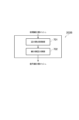
- FIG. 1 is a diagram showing an example of the configuration of a mesh processing system 1 according to an embodiment.
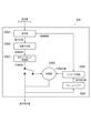
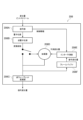
- FIG. 2 is a diagram showing an example of functional blocks of a mesh decoding device 200 according to an embodiment.
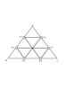
- FIG. 3A is a diagram showing an example of a base mesh and a subdivision mesh.
- FIG. 3B is a diagram showing an example of a base mesh and a subdivision mesh.
- FIG. 4 is a diagram showing an example of a syntax configuration of a basic mesh bit stream.
- FIG. 5 is a diagram showing an example of a syntax configuration of the BPH.
- FIG. 6 is a diagram showing an example of functional blocks of the basic mesh decoding unit 202 of the mesh decoding device 200 according to an embodiment.
- FIG. 7 is a diagram showing an example of functional blocks of the intra-decoding unit 202B of the basic mesh decoding unit 202 of the mesh decoding device 200 according to an embodiment.
- FIG. 8 is a diagram showing an example of the correspondence between the vertices of the basic mesh of a P frame and the vertices of the basic mesh of an I frame.
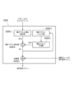
- FIG. 9 is a diagram showing an example of functional blocks of an inter-decoding unit 202E of the basic mesh decoding unit 202 of the mesh decoding device 200 according to an embodiment.
- FIG. 10 is a diagram illustrating an example of a method for calculating the MVP of a vertex to be decoded by the motion vector prediction unit 202E3 of the inter decoding unit 202E of the basic mesh decoding unit 202 of the mesh decoding device 200 according to one embodiment.
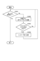
- FIG. 11 shows a flowchart illustrating an example of the operation of the motion vector prediction unit 202E3 of the inter decoding unit 202E of the basic mesh decoding unit 202 of the mesh decoding device 200 according to one embodiment.
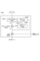
- FIG. 12 is a diagram showing a modified example of the functional blocks of the inter decoding unit 202E of the basic mesh decoding unit 202 of the mesh decoding device 200 according to an embodiment.
- FIG. 11 shows a flowchart illustrating an example of the operation of the motion vector prediction unit 202E3 of the inter decoding unit 202E of the basic mesh decoding unit 202 of the mesh decoding device 200 according to one embodiment.
- FIG. 12 is a diagram showing a modified example of the functional blocks of the
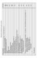
- FIG. 13 is a diagram showing an example of the configuration of the "Basemesh submesh header syntax.”
- FIG. 14 is a diagram showing a modified example of the functional blocks of the basic mesh decoding unit 202 of the mesh decoding device 200 according to an embodiment.
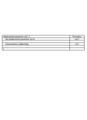
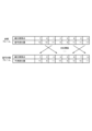
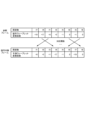
- FIG. 15 is a diagram showing an example of a table for explaining the operation of the basic mesh updating unit 202F.
- FIG. 16 is a diagram showing an example of a table for explaining the operation of the basic mesh updating unit 202F.
- FIG. 17 is a diagram showing an example of a table for explaining the operation of the basic mesh updating unit 202F.
- FIG. 18 is a diagram showing an example of functional blocks of the subdivision unit 203 of the mesh decoding device 200 according to an embodiment.
- FIG. 19 is a diagram showing an example of functional blocks of a basic mesh subdivision unit 203A of the subdivision unit 203 of the mesh decoding device 200 according to an embodiment.
- FIG. 20 is a diagram illustrating an example of a method for dividing a basic surface by the basic surface dividing unit 203A5 of the basic mesh subdivision unit 203A of the subdivision unit 203 in the mesh decoding device 200 according to an embodiment.
- FIG. 21 is a flowchart showing an example of the operation of the basic mesh subdivision unit 203A of the subdivision unit 203 of the mesh decoding device 200 according to an embodiment.
- FIG. 22 is a diagram showing an example of functional blocks of the subdivision mesh adjustment unit 203B of the subdivision unit 203 of the mesh decoding device 200 according to an embodiment.
- FIG. 23 is a diagram showing an example of a case in which an edge division point on a basic surface ABC is moved by the edge division point moving unit 701 of the subdivision mesh adjustment unit 203B of the subdivision unit 203 of the mesh decoding device 200 according to one embodiment.
- Figure 24 is a diagram showing an example of a case in which subdivision surface X within a base surface is re-subdivided by the subdivision surface division unit 702 of the subdivision mesh adjustment unit 203B of the subdivision unit 203 of the mesh decoding device 200 according to one embodiment.
- Figure 25 is a diagram showing an example of a case in which all subdivision surfaces are re-subdivided by the subdivision surface division unit 702 of the subdivision mesh adjustment unit 203B of the subdivision unit 203 of the mesh decoding device 200 according to one embodiment.
- FIG. 26 is a diagram showing an example of functional blocks of the displacement amount decoding unit 206 of the mesh decoding device 200 according to one embodiment (when inter prediction is performed in the spatial domain).
- FIG. 27 is a diagram showing an example of the configuration of a displacement amount bit stream.
- FIG. 28 is a diagram showing an example of a syntax configuration of a DPS.
- FIG. 29 is a diagram showing an example of a syntax configuration of the DPH.
- FIG. 28 is a diagram illustrating an example of a correspondence relationship between subdivision vertices between a reference frame and a current frame to be decoded when inter prediction is performed in the spatial domain.
- FIG. 31 is a diagram showing an example of functional blocks of the displacement amount decoding unit 206 of the mesh decoding device 200 according to an embodiment (when inter prediction is performed in the frequency domain).
- FIG. 32 is a diagram illustrating an example of a frequency correspondence relationship between a reference frame and a current frame to be decoded when inter prediction is performed in the frequency domain.
- FIG. 33 is a flowchart showing an example of the operation of the displacement amount decoding unit 206 of the mesh decoding device 200 according to an embodiment.
- FIG. 34 is a diagram illustrating an example of functional blocks of the displacement amount decoding unit 206 according to the first modification.
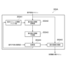
- FIG. 35 is a diagram illustrating an example of functional blocks of the displacement amount decoding unit 206 according to the second modification.
- FIG. 1 is a diagram showing an example of the configuration of a mesh processing system 1 according to this embodiment.
- the mesh processing system 1 includes a mesh encoding device 100 and a mesh decoding device 200.
- the mesh decoding device 200 includes a demultiplexing unit 201, a basic mesh decoding unit 202, a subdivision unit 203, a mesh decoding unit 204, a patch integration unit 205, a displacement amount decoding unit 206, and an image decoding unit 207.
- the basic mesh decoding unit 202, the subdivision unit 203, the mesh decoding unit 204, and the displacement amount decoding unit 206 are configured to perform processing in units of patches into which the mesh is divided, and the results of these processes may then be integrated by the patch integration unit 205.
- the mesh is divided into patch 1, which is made up of base faces 1 and 2, and patch 2, which is made up of base faces 3 and 4.
- the demultiplexing unit 201 is configured to separate the multiplexed bit stream into a basic mesh bit stream, a displacement amount bit stream, and a texture bit stream.
- the base mesh decoding unit 202 is configured to decode the base mesh bitstream and generate and output base meshes.
- the base mesh decoding unit 202 may be configured to decode the base mesh bitstream using, for example, Draco as shown in Non-Patent Document 2.
- the base mesh bitstream may include a base patch header (BPH), which is a collection of control information corresponding to a base mesh patch.
- BPH base patch header
- the base mesh bitstream may include, following the BPH, base mesh patch data that encodes the base mesh patch.
- Figure 5 shows an example of the syntax configuration of a BPH.
- the syntax functions are similar, different syntax names may be used in addition to the syntax mates shown in Figure 5.
- the BPH includes at least a control signal (mdu_face_count_minus1) that specifies the number of base faces contained in the base mesh patch.
- the BPH also includes at least a control signal (mdu_subdivision_method_id) that specifies the type of subdivision method for the base mesh for each base patch.
- the BPH may include a control signal (mdu_max_depth) for identifying an upper limit on the number of recursive subdivisions to be performed for each base mesh patch when recursively generating the number of subdivisions of the base surface.
- mdu_max_depth a control signal for identifying an upper limit on the number of recursive subdivisions to be performed for each base mesh patch when recursively generating the number of subdivisions of the base surface.
- FIG. 7 shows an example of the functional blocks of the intra decoder 202B.
- the sorting unit 202B2 is configured to output vertices by sorting the unordered vertices into a predetermined order.
- connection information decoding unit 202D is configured to convert the connection information of the I frame extracted from the mesh buffer unit 202C into connection information of the P frame.
- the inter-decoding unit 202E can adjust the index of the vertex of the P frame using the pair of vertex indexes A(k) and B(k) that exist as overlapping vertices stored in the specific buffer.
- the motion vector buffer unit 202E2 is configured to sequentially store the MVs output by the motion vector calculation unit 202E4.
- step S1004 the motion vector prediction unit 202E3 adds MV to MVP and adds 1 to N.
- the motion vector prediction unit 202E3 may be configured to set the MVP to 0 if the set of decoded motion vectors is an empty set.
- MV(k) MVP(k)+MVR(k) ... (1) where k is the index of the vertex.
- MV, MVR and MVP are vectors with x, y and z components.
- MVP is used to encode only MVR instead of MV, which is expected to improve encoding efficiency.
- the adder 202E5 is configured to calculate the coordinates of a vertex by adding the MV of the vertex calculated by the motion vector calculation unit 202E4 to the coordinates of the vertex in the reference frame corresponding to the vertex, and to keep the connectivity information (Connectivity) in the reference frame.
- v'i (k) v'j (k)+MV(k)... (2)
- v'i (k) is the coordinate of the kth vertex to be decoded in the frame to be decoded
- v'j (k) is the coordinate of the kth vertex decoded in the reference frame
- the motion vector prediction unit 202E3 calculates the MVP using decoded MVs, so the order of decoding affects the MVP.
- the motion vector prediction unit 202E3 uses multiple prediction methods, it may use a prediction method other than the above-mentioned embodiment or modified example.
- the BSH also includes at least a control signal (smh_num_ref_idx_active_minus1) that calculates a control signal (NumRefIdxActive) when the above-mentioned control signal (smh_num_ref_idx_active_override_flag) is 1.
- the above-mentioned control signal (NumRefIdxActive) is obtained by the following formula.
- the Descriptor of smh_type may be ue(v) or U(8) shown in Fig. 13.
- the base mesh the added subdivision vertices, and their connection information are collectively referred to as the "subdivision mesh.”
- Figures 3A and 3B are diagrams for explaining an example of the operation of generating subdivision vertices from a base mesh.
- the subdivision may be performed, for example, using the mid-edge division method, which connects the midpoints of each edge of each basic face. This results in a basic face being divided into four faces.
- a different subdivision method may be applied to each patch. This allows the displacement amount decoded by the displacement amount decoding unit 206 to be adaptively changed for each patch, which is expected to improve coding performance.
- Information on the divided patch is received as patch_id, which is control information.
- FIG. 18 is a diagram showing an example of the functional blocks of the subdivision unit 203.
- the base mesh subdivision unit 203A may also be configured to predict the number of fine subdivisions of the base surface and calculate the number of subdivisions of the base surface by adding the predicted subdivision number residual to the predicted number of subdivisions of the base surface.
- the basic mesh subdivision unit 203A may also be configured to generate vertices that divide the three sides that make up the basic surface, and to subdivide the basic surface by connecting the generated vertices.
- FIG. 19 shows an example of the functional blocks of the basic mesh subdivision unit 203A
- FIG. 21 is a flowchart showing an example of the operation of the basic mesh subdivision unit 203A.
- the basic surface division number buffer unit 203A1 stores division information of basic surfaces, including the division number of the basic surface, and is configured to output the division information of the basic surface to the basic surface division number reference unit 203A2.
- the size of the basic surface division number buffer unit 203A1 may be set to 1, and the unit may be configured to output the most recently accumulated basic surface division number to the basic surface division number reference unit 203A2.
- the size of the basic surface division number buffer unit 203A1 may be configured to refer only to the last decoded fine division number (the subdivision number decoded immediately before).
- the basic surface division number reference unit 203A2 is configured to output a reference not possible to the basic surface division number prediction unit 203A3 if there is no adjacent basic surface to the basic surface to be decoded, or if there is an adjacent basic surface to the basic surface to be decoded but the division number has not been determined.
- the basic face division number reference unit 203A2 is configured to output the number of divisions to the basic face division number prediction unit 203A3.
- the basic surface division number prediction unit 203A3 is configured to predict the division number (number of subdivisions) of a basic surface based on one or more input division numbers, and output the predicted division number (predicted division number) to the addition unit 203A4.
- the basic surface division number prediction unit 203A3 is configured to output 0 to the addition unit 203A4 if only reference impossible is input from the basic surface division number reference unit 203A2.
- the basic surface division number prediction unit 203A3 may be configured to generate a predicted division number using any of the statistical values such as the average value, maximum value, minimum value, or mode of the input division numbers.
- the addition unit 203A4 is configured to output the division number obtained by adding the prediction division number residual decoded from the prediction residual bit stream and the prediction division number obtained from the basic surface division number prediction unit 203A3 to the basic surface division unit 203A5.
- the basic surface division unit 203A5 is configured to subdivide the basic surface based on the division number input from the addition unit 203A4.
- FIG. 20 shows an example of a case where a basic surface is divided into nine parts. The method of dividing a basic surface by the basic surface division unit 203A5 will be explained with reference to FIG. 20.
- the basic surface division unit 203A5 divides sides BC and CA into N equal parts, generating points B_1, ..., B_(N-1), C_1, ..., C_(N-1), respectively.
- step S2201 the base mesh subdivision unit 203A determines whether the subdivision process for the last base face is complete. If the process is complete, the process ends. If not, the process proceeds to step S2202.
- step S2202 the basic mesh subdivision unit 203A determines whether Depth ⁇ mdu_max_depth.
- Depth is a variable that represents the current depth, with an initial value of 0, and mdu_max_depth represents the maximum depth determined for each base surface.
- step S2202 If the condition in step S2202 is met, the process proceeds to step S2203; if the condition is not met, the process returns to step S2201.
- step S2203 the base mesh subdivision unit 203A determines whether mdu_subdivision_flag at the current depth is 1 or not.
- the base mesh subdivision unit 203A subdivides the base surface.
- the subdivision method is the same as that described in step S2204.
- FIG. 22 shows an example of a functional block of the fine division mesh adjustment unit 203B.
- the subdivision mesh adjustment unit 203B has an edge division point moving unit 701 and a subdivision surface division unit 702.
- FIG. 23 shows an example of moving an edge division point on base face ABC.
- the edge division point moving unit 701 may be configured to move the edge division point of base face ABC to the edge division point of the nearest adjacent base face.
- the subdivision surface division unit 702 is configured to re-subdivide the input subdivision surface and output a composite subdivision surface.
- the subdivision surface division unit 702 may be configured to generate new subdivision surfaces within a base surface by connecting the vertices that make up the subdivision surface to the edge division points of an adjacent base surface.
- the mesh decoding unit 204 is configured to generate and output a decoded mesh using the subdivision mesh generated by the subdivision unit 203 and the displacement amount decoded by the displacement amount decoding unit 206.
- the method of dividing the patch is defined by the mesh encoding device 100.
- the method of dividing the patch may be configured to calculate a normal vector for each base face, select the base face with the most similar normal vector among the adjacent base faces, combine both base faces into the same patch, and repeat this procedure sequentially for the next base face.
- FIG. 26 is a diagram showing an example of the functional blocks of the displacement amount decoding unit 206.
- the displacement amount decoding unit 206 has a decoding unit 206A, an inverse quantization unit 206B, an inverse wavelet transform unit 206C, an adder 206D, an inter prediction unit 206E, and a frame buffer 206F.
- the decoding unit 206A is configured to decode and output level values and control information by performing variable length decoding on the received displacement amount bit stream.
- the level values obtained by variable length decoding are output to the inverse quantization unit 206B, and the control information is output to the inter prediction unit 206E.
- the displacement bit stream may include a DPS (Displacement Parameter Set), which is a collection of control information related to the decoding of the displacement.
- DPS Displayment Parameter Set
- the displacement bitstream may contain, next to the DPH, the encoded displacements that make up the patch.
- the displacement bitstream is structured so that each encoded displacement corresponds to one DPH and one DPS.
- the inverse quantization unit 206B is configured to generate and output transform coefficients by inverse quantizing the level values decoded by the decoding unit 206A.
- the predicted displacement of a certain subdivision vertex in the target frame may be determined probabilistically according to a normal distribution with estimated mean and variance, using the decoded displacements of corresponding subdivision vertices in multiple reference frames.
- the variance may be set to zero and the predicted displacement may be determined uniquely using only the mean.
- the order of the decoded displacement amounts may be rearranged to improve coding efficiency for each frame.
- the adder 206D is configured to calculate and output the decoded displacement amount by adding the prediction residual and the predicted displacement amount.
- the decoded displacement calculated by the adder 206D is also output to the frame buffer 206F.
- step S3504 If the answer is Yes, the operation proceeds to step S3504; if the answer is No, the operation returns to step S3501.
- the displacement amount decoding unit 206 includes a video decoding unit 2061, an image expansion unit 2062, an inverse quantization unit 2063, and an inverse wavelet transformation unit 2064.
- the video decoding unit 2061 is configured to output video by decoding the received displacement amount bit stream using video coding.
- the image expansion unit 2062 is configured to expand and output the video decoded by the video decoding unit 2061 as level values for each image (frame).
- the above-mentioned mesh encoding device 100 and mesh decoding device 200 may be realized as a program that causes a computer to execute each function (each process).
Landscapes
- Engineering & Computer Science (AREA)
- Multimedia (AREA)
- Signal Processing (AREA)
- Physics & Mathematics (AREA)
- General Physics & Mathematics (AREA)
- Theoretical Computer Science (AREA)
- Compression Or Coding Systems Of Tv Signals (AREA)
Abstract
Description
以下、図1~図33を参照して、本実施形態に係るメッシュ処理システムについて説明する。
基本メッシュ復号部202は、基本メッシュビットストリームを復号し、基本メッシュを生成して出力するように構成されている。
イントラ復号部202Bは、例えば、非特許文献2に示すDracoを用いて、Iフレームのビットストリームから、Iフレームの頂点の座標及び接続情報を復号するように構成されている。
図9は、インター復号部202Eの機能ブロックの一例を示す図である。
ここで、kは、頂点のインデックスである。MV、MVR及びMVPは、x成分、y成分及びz成分を有するベクターである。
ここで、v’i(k)は、復号対象のフレームで復号するk番目の頂点の座標であり、v’j(k)は、参照フレームの復号したk番目の頂点の座標であり、MV(k)は、復号対象のフレームのk番目のMVであり、k=1,2…,Kである。
図12に示すように、動きベクトル残差復号部202E1は、Pフレームのビットストリームから、復号対象頂点のMVR及び動きベクトルの予測モードを生成するように構成されている。
変更例1では、動きベクトル残差復号部202E1は、復号済みの頂点の動きベクトルの予測モードに応じてコンテキストモデルを選択し、かかるコンテキストモデルの確率を利用して算術復号を行うことで復号対象頂点の予測モードを生成するように構成されている。
MVPは、復号済みの周りの頂点のMVの単純平均であるが、最近傍頂点のMVであってもよい。
変更例1-2では、動きベクトル予測部202E3は、復号対象フレームと1対1の対応関係を持つ復号済みの他のインターフレーム(Pフレーム)を参照して、復号対象フレームの復号対象頂点のMVPを算出するように構成されている。
変更例1-3では、第1に、動きベクトル予測部202E3は、複数の予測方法を使って、各復号対象頂点において複数のMVPを算出して出力する場合、動きベクトル算出部202E4は、ビットストリームから、予測モードとして、所定のシンタックスを復号するように構成されている。
変更例1-3-1では、動きベクトル算出部202E4は、連続するN個の復号対象頂点において同じ予測モード(最適な予測方法を示す予測モード)を用いるように構成されている。
変更例1-3-2では、第1に、動きベクトル算出部202E4は、上述のビットストリームから復号した上述の所定のシンタックスに基づいて、復号対象フレームと1対1の対応関係を持つ復号済みの他のインターフレームにおいて前記復号対象頂点に対応する頂点の予測モードを、前記前記復号対象頂点の予測モードの予測値とするように構成されている。
以下、基本メッシュ復号部202の変更例について説明する 。
スキップ復号部202Gは、少なくとも1枚の参照フレームを持ち、参照フレーム毎で少なくとも1枚の基本メッシュを保存するメッシュバッファ部202Cから指定された参照用基本メッシュを取り出し、取り出した参照用基本メッシュの頂点の座標をそのまま用いて、復号対象フレームの基本メッシュの頂点の座標を復号するように構成されている。
基本メッシュ更新部202Fは、復号済みのメッシュから取得した基本メッシュの頂点座標と動きベクトルと基本メッシュの頂点の変位量とを加算した値を用いて、基本メッシュの頂点座標を更新し、メッシュバッファ部202Cに更新された基本メッシュを保存し、参照フレームリストを更新するように構成されている。
図13に示す基本メッシュサブメッシュのヘッダのシンタックス(Basemesh submesh header syntax、BSH)において、Description欄は、各シンタックスが、どのように符号化されているかを意味している。また、ue(v)は、符号無し0次指数ゴロム符号であることを意味し、u(n)は、nビットのフラグであることを意味する。
if( smh_num_ref_idx_active_override_flag == 1 )
NumRefIdxActive = smh_num_ref_idx_active_minus1 + 1
else {
if( num_ref_entries[ RlsIdx ] >= bfps_num_ref_idx_default_active_minus1 + 1 )
NumRefIdxActive = bfps_num_ref_idx_default_active_minus1 + 1
else
NumRefIdxActive = num_ref_entries[ RlsIdx ]
}
}
else
NumRefIdxActive = 0
なお、smh_typeのDescriptorは、図13で記載したue(v)でもよいし、U(8)でもよい。また、図6及び図14におけるフレームは、メッシュ(Mesh)又はサブメッシュ(Submesh)のいずれかであってもよい。
細分割部203は、制御情報によって示された細分割手法により、基本メッシュ復号部202によって復号された基本メッシュから、追加された細分割頂点及びそれらの接続情報を生成して出力するように構成されている。
基本メッシュ細分割部203Aは、入力された基本メッシュ及び基本メッシュの分割情報に基づき、基本面及び基本パッチごとの分割数(細分割数)を算出し、かかる分割数に基づいて基本メッシュを細分割し、細分割面を出力するように構成されている。
次に、細分割メッシュ調整部203Bによって行われる処理の具体例について説明する。以下、図22~図25を用いて細分割メッシュ調整部203Bよって行われる処理の一例について説明する。
辺分割点移動部701は、入力された初期細分割面に対して、基本面の辺分割点を隣接基本面の辺分割点のいずれかに移動し、細分割面を出力するように構成されている。
細分割面分割部702は、入力された細分割面を再度細分割し、復号細分割面を出力するように構成されている。
変位量復号部206は、変位量ビットストリームを復号して変位量を生成して出力するように構成されている。
インター予測部206Eは、フレームバッファ206Fから読み出された参照フレームの復号変位量を用いてインター予測を行うことによって、予測変位量を生成して出力するように構成されている。
以下、図34を参照して、上述の第1実施形態の変形例1について、上述の第1実施形態との相違点に着目して説明する。
以下、図35を参照して、上述の第1実施形態の変形例2について、上述の第1実施形態との相違点に着目して説明する。
100…メッシュ符号化装置
200…メッシュ復号部
201…多重分離部
202…基本メッシュ復号部
202A…分離部
202B…イントラ復号部
202B1…任意イントラ復号部
202B2…整列部
202C…メッシュバッファ部
202D…接続情報復号部
202E…インター復号部
202E1…動きベクトル復号部
202E2…動きベクトルバッファ部
202E3…動きベクトル予測部
202E4…動きベクトル算出部
202E5…加算器
202F…スキップ復号部
202G…基本メッシュ更新部
203…細分割部
203A…基本メッシュ細分割部
203A1…基本面分割数バッファ部
203A2…基本面分割数参照部
203A3…基本面分割数予測部
203A4…加算部
203A5…基本面分割部
203B…細分割メッシュ調整部
701…辺分割点移動部
702…細分割面分割部
204…メッシュ復号部
205…パッチ統合部
206…変位量復号部
206A…復号部
206B、2063…逆量子化部
206C、2064…逆ウェーブレット変換部
206D…加算器
206E…インター予測部
206F…フレームバッファ
2062…画像展開部
207、2061…映像復号部
Claims (9)
- メッシュ復号装置であって、
インターフレームのビットストリームから、動きベクトル残差及び動きベクトルの予測モードを生成する動きベクトル残差復号部と、
復号対象頂点の周囲の復号済みの頂点の動きベクトルと、前記復号対象頂点に対応する参照フレーム内の頂点の動きベクトルと、前記復号対象頂点の周囲の復号済みの頂点に対応する前記参照フレーム内の頂点の動きベクトルを用いて、複数の予測方法の中から前記予測モードによって特定される予測方法によって、前記復号対象頂点の動きベクトルの予測値を算出する動きベクトル予測部と、
前記動きベクトルの予測値と前記動きベクトル残差とを加算する動きベクトル算出部とを備えることを特徴とするメッシュ復号装置。 - 前記動きベクトル予測部は、
前記復号対象頂点の周囲の復号済みの頂点に対応する前記参照フレーム内の第1頂点と、前記復号対象頂点に対応する前記参照フレーム内の第2頂点との間の距離を算出し、
前記距離が最も小さい前記第1頂点を選択し、
前記選択した前記第1頂点に対応する復号対象フレーム内の頂点の動きベクトルを、前記復号対象頂点の動きベクトルの予測値とすることを特徴とする請求項1に記載のメッシュ復号装置。 - 前記動きベクトル予測部は、
復号対象フレームと1対1の対応関係を持つ復号済みの他のインターフレームから、前記復号対象頂点に対応する頂点の動きベクトルを抽出し、
前記抽出した動きベクトルを、前記復号対象頂点の動きベクトルの予測値とすることを特徴とする請求項1に記載のメッシュ復号装置。 - 前記動きベクトル予測部は、
復号対象フレームと1対1の対応関係を持つ復号済みの他のインターフレームから、前記復号対象頂点に対応する頂点の動きベクトルと前記復号対象頂点に対応する頂点の動きベクトルの予測値との第1比率関係を抽出し、
前記復号対象頂点の動きベクトルと前記復号対象頂点の動きベクトルの予測値との比率関係が、前記第1比率関係と同じになるように、前記復号対象頂点の動きベクトルの予測値を算出すること特徴とする請求項1に記載のメッシュ復号装置。 - 前記動きベクトル算出部は、連続するN個の復号対象頂点において同じ予測モードを用いることを特徴とする請求項1に記載のメッシュ復号装置。
- 前記動きベクトル算出部は、
前記ビットストリームから復号した所定のシンタックスに基づいて、復号対象フレームと1対1の対応関係を持つ復号済みの他のインターフレームにおいて前記復号対象頂点に対応する頂点の予測モードを、前記前記復号対象頂点の予測モードの予測値とし、
前記ビットストリームから、前記予測モードの予測値との差分を復号し、
前記予測モードの予測値と前記差分とを加算することで、前記復号対象頂点の予測モードを算出することを特徴とする請求項1に記載のメッシュ復号装置。 - 前記動きベクトル残差復号部は、
復号済みの頂点の動きベクトルの予測モードに応じてコンテキストモデルを選択し、
前記コンテキストモデルの確率を利用して算術復号を行うことで、前記復号対象頂点の予測モードを生成し、
前記復号対象頂点の予測モードによって、前記コンテキストモデルの確率を更新することを特徴とする請求項1に記載のメッシュ復号装置。 - メッシュ復号方法であって、
インターフレームのビットストリームから、動きベクトル残差及び動きベクトルの予測モードを生成する工程と、
復号対象頂点の周囲の復号済みの頂点の動きベクトルと、前記復号対象頂点に対応する参照フレーム内の頂点の動きベクトルと、前記復号対象頂点の周囲の復号済みの頂点に対応する前記参照フレーム内の頂点の動きベクトルを用いて、複数の予測方法の中から前記予測モードによって特定される予測方法によって、前記復号対象頂点の動きベクトルの予測値を算出する工程と、
前記動きベクトルの予測値と前記動きベクトル残差とを加算する工程とを有することを特徴とするメッシュ復号方法。 - コンピュータを、メッシュ復号装置として機能させるプログラムであって、
前記メッシュ復号装置は、
インターフレームのビットストリームから、動きベクトル残差及び動きベクトルの予測モードを生成する動きベクトル残差復号部と、
復号対象頂点の周囲の復号済みの頂点の動きベクトルと、前記復号対象頂点に対応する参照フレーム内の頂点の動きベクトルと、前記復号対象頂点の周囲の復号済みの頂点に対応する前記参照フレーム内の頂点の動きベクトルを用いて、複数の予測方法の中から前記予測モードによって特定される予測方法によって、前記復号対象頂点の動きベクトルの予測値を算出する動きベクトル予測部と、
前記動きベクトルの予測値と前記動きベクトル残差とを加算する動きベクトル算出部とを備えることを特徴とするプログラム。
Priority Applications (2)
| Application Number | Priority Date | Filing Date | Title |
|---|---|---|---|
| CN202380062222.3A CN119769092A (zh) | 2023-01-06 | 2023-12-18 | 网格解码装置、网格解码方法及程序产品 |
| US19/061,161 US20250220231A1 (en) | 2023-01-06 | 2025-02-24 | Mesh decoding device, mesh decoding method, and program |
Applications Claiming Priority (2)
| Application Number | Priority Date | Filing Date | Title |
|---|---|---|---|
| JP2023-000930 | 2023-01-06 | ||
| JP2023000930A JP7745577B2 (ja) | 2023-01-06 | 2023-01-06 | メッシュ復号装置、メッシュ復号方法及びプログラム |
Related Child Applications (1)
| Application Number | Title | Priority Date | Filing Date |
|---|---|---|---|
| US19/061,161 Continuation US20250220231A1 (en) | 2023-01-06 | 2025-02-24 | Mesh decoding device, mesh decoding method, and program |
Publications (1)
| Publication Number | Publication Date |
|---|---|
| WO2024147277A1 true WO2024147277A1 (ja) | 2024-07-11 |
Family
ID=91803866
Family Applications (1)
| Application Number | Title | Priority Date | Filing Date |
|---|---|---|---|
| PCT/JP2023/045389 Ceased WO2024147277A1 (ja) | 2023-01-06 | 2023-12-18 | メッシュ復号装置、メッシュ復号方法及びプログラム |
Country Status (4)
| Country | Link |
|---|---|
| US (1) | US20250220231A1 (ja) |
| JP (1) | JP7745577B2 (ja) |
| CN (1) | CN119769092A (ja) |
| WO (1) | WO2024147277A1 (ja) |
Families Citing this family (3)
| Publication number | Priority date | Publication date | Assignee | Title |
|---|---|---|---|---|
| CN121311920A (zh) * | 2023-07-05 | 2026-01-09 | 松下电器(美国)知识产权公司 | 编码方法、解码方法、编码装置及解码装置 |
| MX2025015092A (es) * | 2023-07-06 | 2026-02-03 | Panasonic Ip Corp America | Metodo de codificacion, metodo de decodificacion, dispositivo de codificacion y dispositivo de decodificacion |
| JP2025161653A (ja) * | 2024-04-12 | 2025-10-24 | Kddi株式会社 | メッシュ復号装置、メッシュ復号方法及びプログラム |
-
2023
- 2023-01-06 JP JP2023000930A patent/JP7745577B2/ja active Active
- 2023-12-18 WO PCT/JP2023/045389 patent/WO2024147277A1/ja not_active Ceased
- 2023-12-18 CN CN202380062222.3A patent/CN119769092A/zh active Pending
-
2025
- 2025-02-24 US US19/061,161 patent/US20250220231A1/en active Pending
Non-Patent Citations (2)
| Title |
|---|
| MAMOU K.; ZAHARIA T.; PRETEUX F.; STEFANOSKI N.; OSTERMANN J.: "Frame-based compression of animated meshes in MPEG-4", MULTIMEDIA AND EXPO, 2008 IEEE INTERNATIONAL CONFERENCE ON, IEEE, PISCATAWAY, NJ, USA, 23 June 2008 (2008-06-23), Piscataway, NJ, USA , pages 1121 - 1124, XP032965492, ISBN: 978-1-4244-2570-9, DOI: 10.1109/ICME.2008.4607636 * |
| YANG J-H, KIM C-S, LEE S-U: "COMPRESSION OF 3-D TRIANGLE MESH SEQUENCES BASED ON VERTEX-WISE MOTION VECTOR PREDICTION", IEEE TRANSACTIONS ON CIRCUITS AND SYSTEMS FOR VIDEO TECHNOLOGY, IEEE, USA, vol. 12, no. 12, 1 December 2002 (2002-12-01), USA, pages 1178 - 1184, XP001141949, ISSN: 1051-8215, DOI: 10.1109/TCSVT.2002.806814 * |
Also Published As
| Publication number | Publication date |
|---|---|
| US20250220231A1 (en) | 2025-07-03 |
| JP7745577B2 (ja) | 2025-09-29 |
| CN119769092A (zh) | 2025-04-04 |
| JP2024097467A (ja) | 2024-07-19 |
Similar Documents
| Publication | Publication Date | Title |
|---|---|---|
| JP7745577B2 (ja) | メッシュ復号装置、メッシュ復号方法及びプログラム | |
| KR100627597B1 (ko) | 화상 부호화 장치, 화상 복호 장치, 화상 부호화 방법, 화상 복호 방법, 화상 부호화 프로그램을 기록한 컴퓨터 판독 가능한 기록 매체 및 화상 복호 프로그램을 기록한 컴퓨터 판독 가능한 기록 매체 | |
| WO2012172668A1 (ja) | 動画像符号化方法及び装置並びに動画復号化方法及び装置 | |
| JP2024008741A (ja) | メッシュ復号装置、メッシュ符号化装置、メッシュ復号方法及びプログラム | |
| JP7763727B2 (ja) | メッシュ復号装置、メッシュ符号化装置、メッシュ復号方法及びプログラム | |
| JP7727597B2 (ja) | メッシュ復号装置、メッシュ符号化装置、メッシュ復号方法及びプログラム | |
| WO2024079981A1 (ja) | メッシュ復号装置、メッシュ符号化装置、メッシュ復号方法及びプログラム | |
| JP2024095240A (ja) | メッシュ復号装置、メッシュ復号方法及びプログラム | |
| WO2025009221A1 (ja) | メッシュ復号装置、メッシュ復号方法及びプログラム | |
| JP7680399B2 (ja) | メッシュ復号装置、メッシュ符号化装置、メッシュ復号方法及びプログラム | |
| WO2024014196A1 (ja) | メッシュ復号装置、メッシュ符号化装置、メッシュ復号方法及びプログラム | |
| WO2024079982A1 (ja) | メッシュ復号装置、メッシュ符号化装置、メッシュ復号方法及びプログラム | |
| JP2024152168A (ja) | メッシュ復号装置、メッシュ復号方法及びプログラム | |
| JP2024152167A (ja) | メッシュ復号装置、メッシュ復号方法及びプログラム | |
| JP7769597B2 (ja) | メッシュ復号装置、メッシュ符号化装置、メッシュ復号方法及びプログラム | |
| JP2025009036A (ja) | メッシュ復号装置、メッシュ復号方法及びプログラム | |
| JP7701898B2 (ja) | メッシュ復号装置、メッシュ符号化装置、メッシュ復号方法及びプログラム | |
| CN114007078A (zh) | 一种运动信息候选列表的构建方法、装置及其设备 | |
| JP2025064208A (ja) | メッシュ復号装置、メッシュ復号方法及びプログラム | |
| WO2025009222A1 (ja) | メッシュ復号装置、メッシュ復号方法及びプログラム | |
| JP2025064209A (ja) | メッシュ復号装置、メッシュ復号方法及びプログラム | |
| JP2025064207A (ja) | メッシュ復号装置、メッシュ復号方法及びプログラム | |
| JP2024095239A (ja) | メッシュ復号装置、メッシュ復号方法及びプログラム | |
| HK40064078A (en) | Method, device and equipment for constructing motion information candidate list |
Legal Events
| Date | Code | Title | Description |
|---|---|---|---|
| 121 | Ep: the epo has been informed by wipo that ep was designated in this application |
Ref document number: 23914764 Country of ref document: EP Kind code of ref document: A1 |
|
| WWE | Wipo information: entry into national phase |
Ref document number: 202380062222.3 Country of ref document: CN |
|
| WWP | Wipo information: published in national office |
Ref document number: 202380062222.3 Country of ref document: CN |
|
| NENP | Non-entry into the national phase |
Ref country code: DE |
|
| 122 | Ep: pct application non-entry in european phase |
Ref document number: 23914764 Country of ref document: EP Kind code of ref document: A1 |