WO2024143129A1 - 光学フィルタ - Google Patents
光学フィルタ Download PDFInfo
- Publication number
- WO2024143129A1 WO2024143129A1 PCT/JP2023/045813 JP2023045813W WO2024143129A1 WO 2024143129 A1 WO2024143129 A1 WO 2024143129A1 JP 2023045813 W JP2023045813 W JP 2023045813W WO 2024143129 A1 WO2024143129 A1 WO 2024143129A1
- Authority
- WO
- WIPO (PCT)
- Prior art keywords
- less
- wavelength
- degrees
- transmittance
- incident angle
- Prior art date
- Legal status (The legal status is an assumption and is not a legal conclusion. Google has not performed a legal analysis and makes no representation as to the accuracy of the status listed.)
- Ceased
Links
Images


Classifications
-
- G—PHYSICS
- G02—OPTICS
- G02B—OPTICAL ELEMENTS, SYSTEMS OR APPARATUS
- G02B5/00—Optical elements other than lenses
- G02B5/20—Filters
- G02B5/208—Filters for use with infrared or ultraviolet radiation, e.g. for separating visible light from infrared and/or ultraviolet radiation
-
- B—PERFORMING OPERATIONS; TRANSPORTING
- B32—LAYERED PRODUCTS
- B32B—LAYERED PRODUCTS, i.e. PRODUCTS BUILT-UP OF STRATA OF FLAT OR NON-FLAT, e.g. CELLULAR OR HONEYCOMB, FORM
- B32B7/00—Layered products characterised by the relation between layers; Layered products characterised by the relative orientation of features between layers, or by the relative values of a measurable parameter between layers, i.e. products comprising layers having different physical, chemical or physicochemical properties; Layered products characterised by the interconnection of layers
- B32B7/02—Physical, chemical or physicochemical properties
- B32B7/023—Optical properties
-
- G—PHYSICS
- G02—OPTICS
- G02B—OPTICAL ELEMENTS, SYSTEMS OR APPARATUS
- G02B1/00—Optical elements characterised by the material of which they are made; Optical coatings for optical elements
- G02B1/10—Optical coatings produced by application to, or surface treatment of, optical elements
- G02B1/11—Anti-reflection coatings
- G02B1/113—Anti-reflection coatings using inorganic layer materials only
- G02B1/115—Multilayers
-
- G—PHYSICS
- G02—OPTICS
- G02B—OPTICAL ELEMENTS, SYSTEMS OR APPARATUS
- G02B5/00—Optical elements other than lenses
- G02B5/20—Filters
- G02B5/22—Absorbing filters
-
- G—PHYSICS
- G02—OPTICS
- G02B—OPTICAL ELEMENTS, SYSTEMS OR APPARATUS
- G02B5/00—Optical elements other than lenses
- G02B5/20—Filters
- G02B5/26—Reflecting filters
-
- G—PHYSICS
- G02—OPTICS
- G02B—OPTICAL ELEMENTS, SYSTEMS OR APPARATUS
- G02B5/00—Optical elements other than lenses
- G02B5/20—Filters
- G02B5/28—Interference filters
Definitions
- the present invention relates to an optical filter that transmits visible light and blocks near-infrared light.
- optical filters are used that transmit light in the visible range (hereafter also referred to as “visible light”) and block light in the near-infrared wavelength range (hereafter also referred to as “near-infrared light”) in order to reproduce color tones well and obtain clear images.
- Such optical filters include various types, such as reflective filters that use optical interference to reflect the light to be blocked by alternately laminating thin dielectric films with different refractive indices (dielectric multilayer film) on one or both sides of a transparent substrate, absorptive filters that absorb the light to be blocked by using glass or dyes that absorb light in a specific wavelength range, and filters that combine reflective and absorptive types.
- Patent Document 1 describes an optical filter that contains a copper complex that absorbs light in the near infrared region.
- Patent Document 2 describes an optical filter that contains a dye that absorbs light in the near infrared region.
- Patent Document 3 describes an optical filter that includes glass that absorbs light in the near-infrared region and a reflective layer made of a dielectric multilayer film.
- the optical filter described in Patent Document 1 is made by coating phosphate glass with a copper complex that absorbs light, and has poor moisture resistance and room for improvement in terms of weather resistance.
- the optical filter described in Patent Document 2 blocks a wide range of near-infrared light solely through the absorption characteristics of the dye, which reduces the transmittance in the visible light range, leaving room for improvement.
- the optical film thickness of the dielectric multilayer film changes depending on the angle of incidence of light, so there are concerns about changes in the spectral transmittance curve and the spectral reflectance curve depending on the angle of incidence. For example, if the amount of light taken up in the visible light range changes at high angles of incidence, there is a problem of reduced image reproducibility. In particular, with the recent trend toward lowering the height of camera modules, it is expected that they will be used under high angles of incidence, so there is a demand for optical filters that are less susceptible to the effects of the angle of incidence.
- the present invention aims to provide an optical filter that has excellent weather resistance, excellent transparency in the visible light region, excellent shielding properties in the near-infrared light region, particularly in a wide range including around 1200 nm, and exhibits little change in spectral characteristics even at high angles of incidence.
- the present invention provides an optical filter etc. having the following configuration.
- An optical filter comprising a dielectric multilayer film 1, a substrate having a near-infrared absorbing glass and a resin film, and a dielectric multilayer film 2 in this order, the resin film contains a near-infrared absorbing dye and a resin,
- the near infrared absorbing glass is a fluorophosphate glass containing P, Cu, and F,
- the optical filter satisfies all of the following spectral characteristics (i-1) to (i-5).
- the absolute value of the difference between the average transmittance T 440-600 (0 deg) AVE at a wavelength of 440 to 600 nm and an incident angle of 0 degrees and the average transmittance T 440-600 (60 deg) AVE at a wavelength of 440 to 600 nm and an incident angle of 60 degrees is 15% or less.
- the average transmittance T 440-600 (0 deg) AVE is 75% or more.
- the wavelength IR_T 50 (0 deg ) at which the transmittance is 50% at an incident angle of 0 degrees is in the wavelength range of 580 to 640 nm.
- the average transmittance T 700-800 (0 deg) AVE at a wavelength of 700 to 800 nm and an incident angle of 0 degrees is 1.1% or less.
- the average transmittance T at a wavelength of 800 to 1200 nm and an incident angle of 0 degrees 800-1200 (0 deg) AVE is 5% or less
- the present invention provides an optical filter that has excellent weather resistance, excellent transmittance in the visible light region, excellent shielding properties in the near-infrared light region, particularly in a wide range including around 1200 nm, and exhibits minimal change in spectral characteristics even at high angles of incidence.
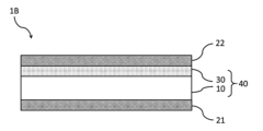
- FIG. 1 is a cross-sectional view illustrating an example of an optical filter according to an embodiment.
- FIG. 2 is a diagram showing the spectral transmittance curves (0 degree transmittance, 60 degree transmittance) of the optical filter of Example 1.
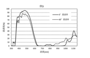
- FIG. 3 is a diagram showing the spectral reflectance curves (5 degree reflectance, 60 degree reflectance, dielectric multilayer film 1 side) of the optical filter of Example 1.
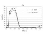
- FIG. 4 is a diagram showing the spectral reflectance curves (5 degree reflectance, 60 degree reflectance, dielectric multilayer film 2 side) of the optical filter of Example 1.
- FIG. 5 is a diagram showing the spectral transmittance curve (0 degree transmittance, 60 degree transmittance) of the optical filter of Example 2.
- FIG. 2 is a diagram showing the spectral transmittance curves (0 degree transmittance, 60 degree transmittance) of the optical filter of Example 1.
- FIG. 3 is a diagram showing the spectral reflectance curves (5 degree reflectance, 60 degree reflectance, dielectric multi
- FIG. 6 is a diagram showing the spectral reflectance curves (5 degree reflectance, 60 degree reflectance, dielectric multilayer film 1 side) of the optical filter of Example 2.
- FIG. 7 is a diagram showing the spectral transmittance curves (0 degree transmittance, 60 degree transmittance) of the optical filter of Example 3.
- FIG. 8 is a diagram showing the spectral transmittance curve (0 degree transmittance, 60 degree transmittance) of the optical filter of Example 4.
- FIG. 9 is a diagram showing the spectral transmittance curve (0 degree transmittance, 60 degree transmittance) of the optical filter of Example 5.
- FIG. 10 is a diagram showing the spectral transmittance curve (0 degree transmittance, 60 degree transmittance) of the optical filter of Example 6.
- the near-infrared absorbing dye may be abbreviated as "NIR dye” and the ultraviolet absorbing dye may be abbreviated as "UV dye”.
- NIR dye near-infrared absorbing dye
- UV dye ultraviolet absorbing dye
- the compound represented by formula (I) is referred to as compound (I).
- the dye consisting of compound (I) is also referred to as dye (I), and the same applies to other dyes.
- the group represented by formula (I) is also referred to as group (I), and the same applies to groups represented by other formulas.
- internal transmittance is the transmittance obtained by subtracting the effect of interface reflection from the measured transmittance, as expressed by the formula ⁇ measured transmittance (incident angle 0 degrees) / (100 - reflectance (incident angle 5 degrees)) ⁇ x 100.
- a transmittance of 90% or more in a specific wavelength range means that the transmittance is not below 90% in the entire wavelength range, i.e., the minimum transmittance is 90% or more in the wavelength range.
- a transmittance of 1% or less in a specific wavelength range means that the transmittance is not more than 1% in the entire wavelength range, i.e., the maximum transmittance is 1% or less in the wavelength range.
- the average transmittance and average internal transmittance in a specific wavelength range are the arithmetic mean of the transmittance and internal transmittance per 1 nm in the wavelength range.
- the reflectance when the dielectric multilayer film side is the incident direction refers to the optical characteristics of the light reflected when measurement light is incident toward the surface of the dielectric multilayer film provided on the optical filter.
- the spectral characteristics can be measured using an ultraviolet-visible spectrophotometer. In this specification, any numerical range expressed by "to” includes the upper and lower limits.
- the optical filter according to this embodiment includes, in this order, a dielectric multilayer film 1, a substrate having a near-infrared absorbing glass and a resin film, and a dielectric multilayer film 2.
- the resin film contains a near-infrared absorbing dye and a resin
- the near-infrared absorbing glass is a fluorophosphate glass containing P, Cu, and F.
- the light blocking property of the optical filter is ensured by the absorption characteristics of the near-infrared absorbing glass and the near-infrared absorbing dye, and the reflection characteristics of the dielectric multilayer film. Since the absorption characteristics are relatively little affected by the incident angle of light, an optical filter can be obtained whose spectral characteristics change little even at a high incident angle.
- Figure 1 is a cross-sectional view showing an example of an optical filter according to one embodiment.
- the optical filter 1B shown in FIG. 1 is an example that includes a dielectric multilayer film 21, a substrate 40 having a near-infrared absorbing glass 10 and a resin film 30, and a dielectric multilayer film 22.
- the optical filter according to this embodiment satisfies all of the following spectral characteristics (i-1) to (i-5).
- i-1 The absolute value of the difference between the average transmittance T 440-600 (0 deg) AVE at a wavelength of 440 to 600 nm and an incident angle of 0 degrees and the average transmittance T 440-600 (60 deg) AVE at a wavelength of 440 to 600 nm and an incident angle of 60 degrees is 15% or less.
- the average transmittance T 440-600 (0 deg) AVE is 75% or more.
- i-3) The wavelength IR_T 50 (0 deg ) at which the transmittance is 50% at an incident angle of 0 degrees is in the wavelength range of 580 to 640 nm.
- the average transmittance T 700-800 (0 deg) AVE at a wavelength of 700 to 800 nm and an incident angle of 0 degrees is 1.1% or less.
- the average transmittance T at a wavelength of 800 to 1200 nm and an incident angle of 0 degrees 800-1200 (0 deg) AVE is 5% or less
- the optical filter according to this embodiment which satisfies all of the spectral characteristics (i-1) to (i-5), has high visible light transmittance as shown by characteristic (i-2), and high near-infrared light blocking performance over a wide range from 800 to 1200 nm as shown by characteristics (i-4) and (i-5).
- characteristic (i-2) the visible light transmittance
- characteristic (i-4) and (i-5) the transmittance over a wide range from 800 to 1200 nm as shown by characteristics (i-4) and (i-5).
- Satisfying the spectral characteristics (i-1) and (i-2) means that the visible light transmittance does not decrease even at a high incidence angle, and the visible light transmittance is excellent.
- the absolute value of the difference in the spectral characteristic (i-1) is preferably 15% or less, more preferably 10% or less.
- the average transmittance T 440-600 (0 deg) AVE is preferably 76% or more, and more preferably 77% or more.
- the spectral characteristics (i-1) and (i-2) can be achieved, for example, by using a dielectric multilayer film with low reflectance in the visible light region, and by using a near-infrared absorbing dye with high transmittance in the visible light region and fluorophosphate glass as the near-infrared absorbing glass.
- Satisfying the spectral characteristic (i-3) means that the near-infrared region can be blocked and visible transmitted light can be efficiently captured.
- the wavelength IR_T 50 (0 deg) is preferably in the range of 580 to 630 nm, more preferably in the range of 590 to 625 nm.
- the spectral characteristic (i-3) can be achieved, for example, by using a fluorophosphate glass, which will be described later, as the near-infrared absorbing glass.
- the spectroscopic characteristic (i-4) means that the near-infrared light shielding property is excellent.
- the average transmittance T 700-800 (0 deg) AVE is preferably 0.6% or less, more preferably 0.3% or less, and particularly preferably 0.1% or less.
- the spectral characteristic (i-4) can be achieved, for example, by using a squarylium dye, which will be described later, as the near-infrared absorbing dye, and a fluorophosphate glass, which will be described later, as the near-infrared absorbing glass.
- the film has excellent light-shielding properties in the near-infrared light region up to a wide range around 1200 nm.
- the average transmittance T 800-1200 (0 deg) AVE is preferably 4% or less, more preferably 3% or less.
- the spectral characteristic (i-5) can be achieved, for example, by using a fluorophosphate glass, which will be described later, as the near-infrared absorbing glass.
- the optical filter according to this embodiment preferably satisfies all of the following spectral characteristics (i-6) to (i-7).
- i-6) When the dielectric multilayer film 1 side is the incident direction, the average reflectance R1 440-650 (5 deg) AVE at a wavelength of 440 to 650 nm and an incident angle of 5 degrees is 1.5% or less.
- i-7) When the dielectric multilayer film 1 side is the incident direction, the average reflectance R1 850-1200 ( 5 deg) AVE at a wavelength of 850 to 1200 nm and an incident angle of 5 degrees is 60% or more.
- the spectral characteristics (i-6) to (i-7) mean that the reflection characteristics of the dielectric multilayer film 1 are substantially reflected, and that the dielectric multilayer film 1 has small visible light reflection characteristics and has reflection characteristics in the near-infrared light region.
- the average reflectance R1 440-650 (5 deg) AVE is more preferably 1.3% or less, further preferably 1.2% or less, and particularly preferably 1.1% or less.
- the average reflectance R1 850-1200 (5 deg) AVE is more preferably 63% or more, further preferably 65% or more, and particularly preferably 70% or more.
- the average reflectance R1 850-1200 (5 deg) AVE is preferably 95% or less, more preferably 90% or less.
- the optical filter according to this embodiment preferably satisfies the following spectral characteristic (i-8).
- i-8 When the dielectric multilayer film 1 side is the incident direction, the average reflectance R1 440-650 (60 deg) AVE at a wavelength of 440 to 650 nm and an incident angle of 60 degrees is 10% or less.
- the spectral characteristic (i-8) substantially reflects the reflection characteristics of the dielectric multilayer film 1, and means that the dielectric multilayer film 1 has small visible light reflection characteristics even at a high incident angle.
- the average reflectance R1 440-650 (60 deg) AVE is more preferably 9% or less, and further preferably 8.5% or less.
- the optical filter according to this embodiment preferably satisfies all of the following spectral characteristics (i-9) to (i-10).
- i-9) When the dielectric multilayer film 2 side is the direction of incidence, the average reflectance R2 440-650 (5 deg) AVE at a wavelength of 440 to 650 nm and an incident angle of 5 degrees is less than 2.0%.
- i-10) When the dielectric multilayer film 2 side is the direction of incidence, the average reflectance R2 700-850 ( 5 deg) AVE at a wavelength of 700 to 850 nm and an incident angle of 5 degrees is 1.2% or less.
- the spectral characteristics (i-9) to (i-10) substantially reflect the reflection characteristics of the dielectric multilayer film 2, and mean that the dielectric multilayer film 2 is an anti-reflection film having small reflection characteristics in both the visible light region and the near-infrared light region.
- the average reflectance R2 440-650 (5 deg) AVE is more preferably 1.70% or less, and further preferably 1.53% or less.
- the average reflectance R2 700-850 (5 deg) AVE is more preferably 1.1% or less, further preferably 1.0% or less, and particularly preferably 0.8% or less.
- the optical filter according to this embodiment preferably satisfies all of the following spectral characteristics (i-11) to (i-12).
- i-11 When the dielectric multilayer film 2 side is the incident direction, the average reflectance R2 440-650 (60 deg) AVE at a wavelength of 440 to 650 nm and an incident angle of 60 degrees is less than 10%.
- the average reflectance R2 700-850 ( 60 deg) AVE at a wavelength of 700 to 850 nm and an incident angle of 60 degrees is 8% or less.
- the spectral characteristics (i-11) to (i-12) mean that the reflection characteristics of the dielectric multilayer film 2 are substantially reflected, and that the dielectric multilayer film 2 is an anti-reflection film having small reflection characteristics in both the visible light region and the near-infrared light region even at a high incident angle.
- the average reflectance R2 440-650 (60 deg) AVE is more preferably 9% or less, and further preferably 8.5% or less.
- the average reflectance R2 700-850 (60 deg) AVE is more preferably 7.5% or less, further preferably 7.0% or less, and particularly preferably 6% or less.
- the optical filter according to this embodiment preferably satisfies the following spectral characteristic (i-13).
- i-13 When the dielectric multilayer film 1 side is the incident direction, the absolute value of the difference between the wavelength IR_R 50 (5 deg) at which the reflectance is 50% at an incident angle of 5 degrees in the wavelength range of 750 to 900 nm, and the wavelength IR_T 50 (5 deg) at which the transmittance is 50% at an incident angle of 5 degrees in the wavelength range of 500 to 700 nm, is 160 nm or more. Satisfying the spectral characteristic (i-13) means that the light-shielding region of the reflection characteristic and the light-shielding region of the absorption characteristic are separated from each other.
- the absolute value of the difference in the spectral characteristic (i-13) is more preferably 165 nm or more, further preferably 170 nm or more, and particularly preferably 185 nm or more.
- the optical filter according to this embodiment preferably satisfies all of the following spectral characteristics (i-14) to (i-15).
- the amount of absorption loss XY at wavelengths X to Y nm is defined as follows.
- (Absorption loss amount X ⁇ Y ) [%] 100 ⁇ (Transmittance at an incident angle of 5 degrees) ⁇ (Reflectance at an incident angle of 5 degrees)
- the average absorption loss amount 700-800 in the wavelength range of 700 to 800 nm is 25% or more.
- the average absorption loss amount 850-1000 in the wavelength range of 850 to 1000 nm is 17% or more.
- the average value of the absorption loss amount 700-800 is more preferably 26.5% or more, and further preferably 28% or more.
- the average value of the absorption loss amount 850-1000 is more preferably 18% or more, and further preferably 20% or more.
- the spectral characteristics (i-14) to (i-15) can be achieved, for example, by using a near-infrared absorbing dye having a maximum absorption wavelength in the wavelength range of 700 to 800 nm.
- the near-infrared absorbing glass in the optical filter according to this embodiment is a fluorophosphate glass containing P, Cu, and F (hereinafter, also referred to as the fluorophosphate glass of this embodiment, or simply as fluorophosphate glass or glass).
- the inclusion of Cu makes it possible to maintain a high transmittance of light in the visible range while keeping the transmittance of light in the near-infrared range low. Also, the inclusion of F in the glass makes it possible to improve weather resistance, such as moisture resistance.
- the components that may constitute the fluorophosphate glass of this embodiment and their suitable contents are described below.
- the content of each component and the total content are expressed in mass %.
- the transmittance of the glass of this embodiment includes the reflective properties of the glass surface (i.e., it is not the internal transmittance of the glass).
- P is contained as P 5+ .
- P5 + is the main component forming fluorophosphate glass and is an essential component for enhancing the near-infrared cutoff property. If the content of P5+ is 30% or more, the effect is sufficiently obtained, and if it is 70% or less, problems such as glass becoming unstable or weather resistance decreasing are unlikely to occur. Therefore, the content of P5 + is preferably 30 to 70%. More preferably, it is 31% or more, even more preferably 32% or more, even more preferably 33% or more, and more preferably 60% or less, even more preferably 50% or less, even more preferably 45% or less, and most preferably 43% or less.
- As the raw material for P5 + it is preferable to use phosphoric acid or a salt thereof from the viewpoint of suppressing corrosion of the platinum crucible and suppressing volatilization of the components.
- F is contained as F 2 ⁇ .
- F- is an essential component for stabilizing glass and improving weather resistance.
- the content of F- contained in glass is expressed as an external percentage when the component elements other than F- contained in glass are taken as 100 mass%.
- the content of F- is preferably 5 to 70% by external percentage. If the content of F- is 5% or more by external percentage, the effect of weather resistance is sufficiently obtained, and if the content of F- is 70% or less by external percentage, problems such as a decrease in the transmittance of light in the visible range, a decrease in mechanical properties such as strength, hardness, and elastic modulus, and an increase in ultraviolet transmittance are unlikely to occur.
- the content of F- is 6% or more by external percentage, even more preferably, the content of F- is 8% or more by external percentage, even more preferably, the content of F- is 8.5% or more by external percentage, and most preferably, the content of F- is 10% or more by external percentage, and more preferably, the content of F- is 60% or less by external percentage, even more preferably, the content of F- is 50% or less by external percentage, even more preferably, the content of F- is 40% or less by external percentage, and most preferably, the content of F- is 25% or less by external percentage.
- Cu is contained as Cu + or Cu2 + , but the contents described in this specification are all when Cu2 + is present.
- Cu 2+ is an essential component for cutting near-infrared rays.
- the content of Cu 2+ is preferably 1 to 20%. If the content of Cu 2+ is 1% or more, the effect of increasing the light transmittance in the visible region of the glass obtained when co-added with Mo is sufficiently obtained, and if the content of Cu 2+ is 20% or less, problems such as the generation of devitrification foreign matter in the glass and the decrease in the light transmittance in the visible region are unlikely to occur.
- it is 4.5% or more, even more preferably 6% or more, even more preferably 7.5% or more, most preferably 7.8% or more, and more preferably 18% or less, even more preferably 16% or less, even more preferably 13% or less, and most preferably 12% or less.
- the total Cu content is the total amount of Cu expressed in mass%, including monovalent, divalent, and other valences present.
- the range of the total Cu content in the glass is preferably 1 to 20 mass%.
- the total Cu content is 1 mass% or more, the near-infrared cut effect can be sufficiently obtained even if the glass plate thickness is thin, and when it is 20 mass% or less, the decrease in visible transmittance can be suppressed.
- the content of Cu + expressed in mass% can be determined in a range such that (Cu + /total Cu content) x 100 [%] is 0.01 to 4.0%.
- Al 3+ is a component that forms glass and is a component for increasing the strength of glass, increasing the weather resistance of glass, and the like.
- glass contains Al 3+
- the content of Al 3+ is preferably 0 to 20%. It is more preferably 2% or more, even more preferably 3% or more, even more preferably 3.5% or more, and most preferably 5% or more, and also more preferably 18% or less, even more preferably 15% or less, even more preferably 13% or less, and most preferably 10% or less.
- AlF3 As the raw material for Al3 + , AlF3 , Al2O3 , Al(OH) 3 , etc. can be used. Among them, it is preferable to use AlF3 , since problems such as an increase in melting temperature, generation of unmelted matter, and instability of the glass due to a decrease in the amount of F- charged are unlikely to occur.
- Li + is a component for lowering the melting temperature of glass, lowering the liquidus temperature of glass, stabilizing glass, etc.
- the Li + content is preferably 0 to 20%. If the Li + content is 20% or less, problems such as glass becoming unstable and near-infrared cutoff properties decreasing are unlikely to occur. It is more preferably 18% or less, even more preferably 15% or less, even more preferably 12% or less, and most preferably 10% or less.
- the electric field generated by the negative charge has the function of inhibiting the movement of electrons (e - ) between the Cu + and Mo 6 + (Cu + ⁇ Cu 2 + + e - ) and (Mo 6 + + e - ⁇ Mo 5 + ).
- the negative charge of the oxygen ions is electrically neutralized by the positive charge carried by Na + .
- the transfer of electrons between the Cu + and Mo5 + is promoted, the proportion of Cu + having optical absorption characteristics in the visible region is reduced, and the optical transmittance in the visible region is increased.
- the Na + content is preferably 0.1 to 25%. If the Na + content is 25% or less, the glass is less likely to become unstable. It is more preferably 0.5% or more, even more preferably 1% or more, even more preferably 2% or more, and most preferably 3% or more, and more preferably 20% or less, even more preferably 18% or less, even more preferably 14% or less, and most preferably 10% or less.
- K + is a component that has the effect of lowering the melting temperature of glass, lowering the liquidus temperature of glass, etc.
- the content of K + is preferably 0 to 25%. If the content of K + is 25% or less, it is preferable because the glass is less likely to become unstable. It is more preferably 23% or less, even more preferably 20% or less, even more preferably 18% or less, and most preferably 15% or less.
- R + (one or more components selected from Li + , Na + , and K + ) is a component for lowering the melting temperature of glass, lowering the liquidus temperature of glass, stabilizing glass, and the like. If the total amount of R + , that is, the total amount of Li + , Na + , and K + ( ⁇ R + ) is 0.1% or more, the effect is sufficiently obtained, and if it is 30% or less, it is preferable because the glass is less likely to become unstable. Therefore, the content of ⁇ R + is preferably 0.1 to 30%.
- it is 1% or more, even more preferably 3% or more, even more preferably 5% or more, most preferably 8% or more, and more preferably 28% or less, even more preferably 27% or less, even more preferably 26% or less, and most preferably 25% or less.
- Mg 2+ is a component for lowering the melting temperature of glass, lowering the liquidus temperature of glass, stabilizing glass, increasing the strength of glass, etc.
- the content of Mg 2+ is preferably 0 to 10%. If the content of Mg 2+ is 10% or less, problems such as glass becoming unstable and near-infrared cutoff properties decreasing are unlikely to occur. It is more preferably 8% or less, even more preferably 6% or less, even more preferably 5% or less, and most preferably 3% or less.
- Ca 2+ is a component for lowering the melting temperature of glass, lowering the liquidus temperature of glass, stabilizing glass, increasing the strength of glass, etc.
- the Ca 2+ content is preferably 0 to 20%. If the Ca 2+ content is 20% or less, problems such as glass becoming unstable and near-infrared cutoff properties decreasing are unlikely to occur. It is more preferably 0.1% or more, even more preferably 1% or more, even more preferably 2% or more, and most preferably 3% or more, and more preferably 18% or less, even more preferably 15% or less, even more preferably 10% or less, and most preferably 6% or less.
- Sr2 + is a component for lowering the melting temperature of glass, lowering the liquidus temperature of glass, stabilizing glass, etc.
- the content of Sr2+ is preferably 0 to 30%. If the content of Sr2 + is 30% or less, problems such as glass becoming unstable and near-infrared cutoff properties decreasing are unlikely to occur. It is more preferably 0.1% or more, even more preferably 1% or more, even more preferably 3% or more, and most preferably 5% or more, and more preferably 25% or less, even more preferably 20% or less, even more preferably 15% or less, and most preferably 10% or less.
- Ba2 + is a component for lowering the melting temperature of glass, lowering the liquidus temperature of glass, stabilizing glass, etc.
- the content of Ba2+ is preferably 0 to 40%. If the content of Ba2 + is 40% or less, problems such as glass becoming unstable and near-infrared cutoff properties decreasing are unlikely to occur. It is more preferably 0.1% or more, even more preferably 5% or more, even more preferably 10% or more, most preferably 15% or more, and more preferably 35% or less, even more preferably 30% or less, even more preferably 25% or less, and most preferably 23% or less.
- R 2+ (one or more components selected from Mg 2+ , Ca 2+ , Sr 2+ , and Ba 2+ ) is a component for lowering the melting temperature of glass, lowering the liquidus temperature of glass, stabilizing glass, and the like. If the total amount of R 2+ , i.e., the total amount of Mg 2+ , Ca 2+ , Sr 2+ , and Ba 2+ ( ⁇ R 2+ ) is 10% or more, the effect is sufficiently obtained, and if it is 45% or less, the glass is less likely to become unstable. Therefore, the content of ⁇ R 2+ is preferably 10 to 45%.
- it is 15% or more, even more preferably 20% or more, even more preferably 23% or more, most preferably 25% or more, and more preferably 40% or less, even more preferably 35% or less, even more preferably 33% or less, and most preferably 30% or less.
- Zn 2+ has the effect of lowering the melting temperature of glass, lowering the liquidus temperature of glass, etc.
- the content of Zn 2+ is preferably 0 to 30%. If the content of Zn 2+ is 30% or less, problems such as glass becoming unstable, deterioration of the solubility of glass, and deterioration of near-infrared cutoff properties are unlikely to occur. It is more preferably 20% or less, even more preferably 15% or less, even more preferably 10% or less, and most preferably 5% or less.
- Rb + is a component that has the effect of lowering the melting temperature of glass, lowering the liquidus temperature of glass, etc.
- the content of Rb + is preferably 0 to 10%. If the content of Rb + is 10% or less, the glass is less likely to become unstable. It is more preferably 8% or less, even more preferably 6% or less, even more preferably 4% or less, and most preferably 2% or less.
- Cs + is a component that has the effect of lowering the melting temperature of glass, lowering the liquidus temperature of glass, etc.
- the content of Cs + is preferably 0 to 10%. If the content of Cs + is 10% or less, the glass is less likely to become unstable. It is more preferably 8% or less, even more preferably 6% or less, even more preferably 4% or less, and most preferably 2% or less.
- B3 + may be contained in the range of 20% or less in order to stabilize the glass. If the content of B3+ is 20% or less, problems such as deterioration of the weather resistance of the glass and deterioration of the near-infrared cutoff property are unlikely to occur. It is more preferably 15% or less, even more preferably 10% or less, even more preferably 8% or less, and most preferably 5% or less.
- Mo is contained as Mo5 + or Mo6 + , but in this specification, the content is described as Mo6 + .
- Mo6 + is a component for increasing the transmittance of light in the visible region through glass. It is known that Mo exists as Mo 6+ (hexavalent) in glass. However, when Mo and Cu are co-doped in phosphate glass, Cu + in the glass releases electrons (e - ) to become Cu 2+ (Cu + ⁇ Cu 2+ +e - ), and Mo 6+ receives the electrons released by Cu + to become Mo 5+ (pentavalent) (Mo 6+ +e - ⁇ Mo 5+ ).
- the content of Mo 6+ is preferably 0 to 4%.
- Mo 6+ When Mo 6+ is contained, its content is preferably 0.01 to 4%. If the content of Mo 6+ is 0.01% or more, the effect of increasing the light transmittance of the glass in the visible region is sufficiently obtained, and if the content is 4% or less, problems such as a decrease in the near-infrared cutoff property and the generation of devitrification in the glass are unlikely to occur. It is more preferably 0.05% or more, even more preferably 0.1% or more, even more preferably 0.2% or more, most preferably 0.3% or more, and also more preferably 3.5% or less, even more preferably 3% or less, even more preferably 2% or less, and most preferably 1% or less.
- the content ratio of Mo 6+ and Cu 2+ is preferably 0.01 to 0.39 on a mass basis.
- the absorption of light of wavelengths in the visible light range by Cu + can be sufficiently suppressed, and the absorption of light of wavelengths in the near-infrared range by Cu 2+ can be sufficiently promoted.
- the decrease in the transmittance in the visible range by Mo 5+ can be suppressed.
- it is 0.02 or more, even more preferably 0.03 or more, even more preferably 0.05 or more, and most preferably 0.1 or more, and also more preferably 0.35 or less, even more preferably 0.3 or less, even more preferably 0.25 or less, and most preferably 0.2 or less.
- SiO2 , GeO2 , ZrO2 , SnO2 , TiO2 , CeO2, WO3 , Y2O3 , La2O3 , Gd2O3 , Yb2O3 , and Nb2O5 may be contained in a range of 10 % or less in order to improve the weather resistance of the glass. If the content of these components is 10% or less, problems such as the generation of devitrification in the glass and the deterioration of the near-infrared cutoff property are unlikely to occur. It is preferably 4% or less, more preferably 3% or less, even more preferably 2% or less, and even more preferably 1% or less.
- Fe2O3 , Cr2O3 , Bi2O3 , NiO, V2O5 , MnO2 and CoO are all components that , when present in glass, reduce the transmittance of light in the visible region. Therefore, it is preferable that these components are not substantially contained in the glass.
- substantially not contained in the glass means that they are not contained except for unavoidable impurities, and that the components are not actively added. Specifically, it means that the content of each of these components in the glass is about 100 mass ppm or less.
- the fluorophosphate glass of this embodiment preferably has a thermal expansion coefficient in the range of 30°C to 300°C of 60 ⁇ 10 -7 /°C to 180 ⁇ 10 -7 /°C, more preferably 65 ⁇ 10 -7 /°C to 175 ⁇ 10 -7 /°C, and even more preferably 70 ⁇ 10 -7 /°C to 170 ⁇ 10 -7 /°C.
- the fluorophosphate glass in the optical filter according to this embodiment preferably satisfies all of the following spectral characteristics (ii-1) to (ii-3).
- ii-1 The wavelength IR_T 50 (0 deg) at which the transmittance is 50% at an incident angle of 0 degrees is in the wavelength range of 590 to 640 nm.
- ii-2) The transmittance T 700 (0 deg) at a wavelength of 700 nm and an incident angle of 0 degrees is 25% or less.
- the average transmittance T 700-800 (0 deg) AVE at a wavelength of 700 to 800 nm and an incident angle of 0 degrees is 10% or less.
- the near-infrared absorbing glass transmits visible light, with the region of 590 to 640 nm being the boundary between the transmission band and the absorption band, and the absorption band starting from 700 nm. This allows for the production of an optical filter that is excellent in the transmittance of visible light and the blocking of near-infrared light.
- the wavelength IR_T 50 (0 deg) is more preferably 590 to 630 nm, and further preferably 590 to 624 nm.
- the transmittance T 700 (0 deg) is more preferably 20% or less, further preferably 15% or less, and particularly preferably 10% or less.
- the average transmittance T 700-800 (0 deg) AVE is more preferably 9.8% or less, and further preferably 9.7% or less.
- the fluorophosphate glass in the optical filter according to this embodiment preferably satisfies the following spectral characteristic (ii-4), thereby providing an optical filter with excellent blocking properties for near-infrared light of 800 nm or more.
- the average transmittance T 800-1200 (0 deg) AVE at a wavelength of 800 to 1200 nm and an incident angle of 0 degree is 10% or less.
- the average transmittance T 800-1200 (0 deg) AVE is more preferably 8% or less, and further preferably 6% or less.
- the fluorophosphate glass in the optical filter according to this embodiment preferably has a thickness of 0.5 mm or less, more preferably 0.4 mm or less. From the viewpoint of maintaining element strength, the thickness is preferably 0.1 mm or more, more preferably 0.15 mm or more.
- the optical filter according to this embodiment includes a dielectric multilayer film 1 and a dielectric multilayer film 2. At least one of the dielectric multilayer films is preferably designed as a reflective film that reflects a part of near-infrared light (hereinafter also referred to as an "NIR reflective film").
- the other dielectric multilayer films may be designed as reflective films having a reflection range other than the near-infrared range, or as anti-reflection films.
- the NIR reflective film preferably has wavelength selectivity that, for example, transmits visible light, transmits near-infrared light in the transmission region of the absorbing layer, and mainly reflects other near-infrared light.
- At least one of the dielectric multilayer films is a reflective film having a reflecting characteristic in the near-infrared light region of wavelengths of 850 to 1200 nm, and it is preferable that light is blocked by such a characteristic.
- the dielectric multilayer film serving as the reflective film has small changes in the reflection characteristics in the visible light region, so that an optical filter can be obtained in which the spectral characteristics in the visible light region are less likely to change depending on the angle of incidence and ripples are reduced.
- at least one of the dielectric multilayer films is designed as a reflective film that does not reflect visible light but reflects near-infrared light (wavelength 800 to 1200 nm) at an incident angle of light of 0 to 60 degrees.
- the other dielectric multilayer films are preferably designed as anti-reflection layers having small reflection characteristics in both the visible light region and the near-infrared light region, as shown in the spectral characteristics (i-9) to (i-12) of the optical filter described above.
- the dielectric multilayer film is, for example, a dielectric multilayer film formed by laminating dielectric films having different refractive indices. More specifically, examples of the dielectric multilayer film include a low refractive index dielectric film (low refractive index film), a medium refractive index dielectric film (medium refractive index film), and a high refractive index dielectric film (high refractive index film), and the dielectric multilayer film is formed by laminating two or more of these.
- the high refractive index film preferably has a refractive index of 1.6 or more at a wavelength of 500 nm, more preferably 1.8 to 2.5, and particularly preferably 2.2 to 2.5.
- Examples of materials for the high refractive index film include Ta 2 O 5 , TiO 2 , TiO, and Nb 2 O 5.
- Other commercially available products include OS50 (Ti 3 O 5 ), OS10 (Ti 4 O 7 ), OA500 (a mixture of Ta 2 O 5 and ZrO 2 ), and OA600 (a mixture of Ta 2 O 5 and TiO 2 ), all manufactured by Canon Optron.
- TiO 2 is preferred from the viewpoints of film forming properties, reproducibility in refractive index, and stability.
- the medium refractive index film preferably has a refractive index of 1.6 or more and less than 2.2 at a wavelength of 500 nm.
- materials for the medium refractive index film include ZrO 2 , Nb 2 O 5 , Al 2 O 3 , and HfO 2 , as well as OM-4, OM-6 (a mixture of Al 2 O 3 and ZrO 2 ) and OA-100 sold by Canon Optron, and H4 and M2 (alumina lanthania) sold by Merck.
- Al 2 O 3 -based compounds and mixtures of Al 2 O 3 and ZrO 2 are preferred from the standpoint of film-forming properties, reproducibility in refractive index, and stability.
- the low refractive index film preferably has a refractive index of less than 1.6 at a wavelength of 500 nm, more preferably 1.38 to 1.5.
- materials for the low refractive index film include SiO 2 , SiO x N y, and MgF 2.
- Other commercially available products include S4F and S5F (a mixture of SiO 2 and Al 2 O 3 ) manufactured by Canon Optron. Of these, SiO 2 is preferred from the standpoint of reproducibility, stability, and economy in film formation.
- the ratio of [sum T(H) of QWOTs of dielectric films having a relatively high refractive index]/[sum T(L) of QWOTs of dielectric films having a relatively low refractive index] is preferably 1.6 or more. This makes it easy to obtain a dielectric multilayer film that satisfies the above-mentioned spectral characteristics of reflecting near-infrared light with a wavelength of 800 to 1100 nm and suppressing reflection of visible light, and it is preferable that at least the dielectric multilayer film laminated on the light incident side satisfies this ratio relationship.
- QWOT Quality of Wave Optical Thickness
- the sum of the QWOTs T(H) is the sum of the QWOTs of the high refractive index films
- the sum of the QWOTs T(L) is the sum of the QWOTs of the low refractive index films.
- the dielectric multilayer film is a laminate of a low refractive index film and a medium refractive index film
- the sum of the QWOTs T(H) is the sum of the QWOTs of the medium refractive index films
- the sum of the QWOTs T(L) is the sum of the QWOTs of the low refractive index films.
- the dielectric multilayer film is a laminate of a medium refractive index film and a high refractive index film
- the sum of the QWOTs T(H) is the sum of the QWOTs of the high refractive index films
- the sum of the QWOTs T(L) is the sum of the QWOTs of the medium refractive index films.
- the dielectric multilayer film is preferably a multilayer film in which 10 or more H2 layers and M2 layers defined below are alternately laminated.
- H2 layer A single layer having a refractive index of 1.8 to 2.5 and a QWOT of 1.1 to 3.5
- M2 layer A single layer or multiple layers present between two H2 layers and having a sum of QWOT of 1.2 to 1.8
- the specific laminated structure is a structure in which single layers ( H2 layers) having a large refractive index and optical thickness and layers ( M2 layers) having a total optical thickness within a predetermined range are alternately laminated in 10 or more layers.
- H2 layers single layers
- M2 layers layers having a total optical thickness within a predetermined range
- the M2 layer may be a single layer or multiple layers as long as it has a predetermined optical thickness, but it is preferable that the M2 layer is composed of multiple layers in order to obtain smoother spectral characteristics, and the minimum thickness of the single layer is preferably 5 nm or more, more preferably 10 nm or more.
- the refractive index of the dielectric film constituting the M2 layer is preferably the same as or lower than the refractive index of the H2 layer .
- the dielectric multilayer film having the above-mentioned specific laminated structure is designed as at least a reflective film.
- the layer closest to the near-infrared absorbing glass out of the H2 layer and the M2 layer is the H2 layer.
- the H2 layer closest to the near-infrared absorbing glass may be laminated directly on the near-infrared absorbing glass, or another layer that does not correspond to either the H2 layer or the M2 layer may be present between the H2 layer closest to the near-infrared absorbing glass and the near-infrared absorbing glass.
- the total number of laminated layers in the dielectric multilayer film is preferably 10 or more, more preferably 20 or more, and even more preferably 30 or more.
- the total number of laminated layers is preferably 110 or less, more preferably 80 or less, and even more preferably 60 or less.
- the thickness (physical thickness) of the dielectric multilayer film designed as a reflective film is preferably 1 to 6 ⁇ m overall.
- the dielectric multilayer film that is on the sensor side is usually preferably designed as an antireflection layer.
- the total number of layers of the dielectric multilayer film designed as an antireflection layer is preferably 40 layers or less, more preferably 30 layers or less, further preferably 20 layers or less, and is preferably 6 layers or more.
- the thickness (physical thickness) of the dielectric multilayer film designed as an antireflection layer is preferably 0.2 to 1.0 ⁇ m overall.
- the dielectric multilayer film can be formed using, for example, vacuum deposition processes such as CVD, sputtering, and vacuum deposition, or wet deposition processes such as spraying and dipping.
- vacuum deposition processes such as CVD, sputtering, and vacuum deposition
- wet deposition processes such as spraying and dipping.
- the dielectric multilayer film laminated on the glass surface is usually placed on the lens side, and the dielectric multilayer film laminated on the resin film surface is placed on the sensor side. Therefore, it is preferable to mount the optical filter according to this embodiment so that dielectric multilayer film 1 is placed on the lens side, and dielectric multilayer film 2 is placed on the sensor side.
- the resin film in the optical filter according to this embodiment contains a resin and a near-infrared absorbing dye.
- the resin refers to the resin that constitutes the resin film.
- the near-infrared absorbing dye is preferably one that has a maximum absorption wavelength in the resin at 740 to 800 nm.
- the near-infrared light absorption region of the fluorophosphate glass containing Cu, etc. is on the short wavelength side, so the spectral characteristics of the dye can be utilized more effectively when combined with glass.
- the near-infrared absorbing dye may be at least one selected from the group consisting of cyanine dyes, phthalocyanine dyes, squarylium dyes, naphthalocyanine dyes, and diimonium dyes, and may be used alone or in combination.
- squarylium dyes and cyanine dyes are preferred from the viewpoint of being able to steeply absorb light in the 740 to 800 nm range and thus being able to easily exert the effects of the present invention.
- the content of the near-infrared absorbing dye in the resin film is preferably 0.1 to 30 parts by mass, and more preferably 0.1 to 20 parts by mass, per 100 parts by mass of resin. When two or more types of compounds are combined, the above content is the total of the respective compounds.
- the resin film may contain other dyes, for example, ultraviolet light absorbing dyes, to the extent that the effect of the present invention is not impaired.
- ultraviolet light absorbing dyes include oxazole dyes, merocyanine dyes, cyanine dyes, naphthalimide dyes, oxadiazole dyes, oxazine dyes, oxazolidine dyes, naphthalic acid dyes, styryl dyes, anthracene dyes, cyclic carbonyl dyes, and triazole dyes.
- merocyanine dyes are particularly preferred.
- one type may be used alone, or two or more types may be used in combination.
- the resin is not limited as long as it is a transparent resin, and one or more transparent resins selected from polyester resin, acrylic resin, epoxy resin, ene-thiol resin, polycarbonate resin, polyether resin, polyarylate resin, polysulfone resin, polyethersulfone resin, polyparaphenylene resin, polyarylene ether phosphine oxide resin, polyamide resin, polyimide resin, polyamideimide resin, polyolefin resin, cyclic olefin resin, polyurethane resin, polystyrene resin, etc. may be used.
- One of these resins may be used alone, or two or more may be used in combination. From the viewpoints of the spectral characteristics, glass transition point (Tg) and adhesion of the resin film, one or more resins selected from polyimide resins, polycarbonate resins, polyester resins and acrylic resins are preferred.
- dyes When multiple dyes are used, they may be contained in the same resin film, or each may be contained in a separate resin film.
- the resin film can be formed by dissolving or dispersing the dye, resin or raw material components of the resin, and each component that is mixed as necessary in a solvent to prepare a coating liquid, applying this to a support, drying it, and further curing it as necessary.
- the support in this case may be the near-infrared absorbing glass used in this filter, or a peelable support that is used only when forming the resin film.
- the solvent may be a dispersion medium in which the dye can be stably dispersed, or a solvent in which the dye can be dissolved.
- the coating liquid may also contain a surfactant to improve voids caused by tiny bubbles, depressions caused by the adhesion of foreign matter, and repellency during the drying process.
- a surfactant to improve voids caused by tiny bubbles, depressions caused by the adhesion of foreign matter, and repellency during the drying process.
- the dip coating method, cast coating method, spin coating method, etc. can be used to apply the coating liquid.
- a resin film is formed by drying. If the coating liquid contains raw materials for a transparent resin, a curing process such as heat curing or light curing is further performed.
- the resin film can also be produced in a film-like form by extrusion molding.
- the resulting film-like resin film can be laminated onto phosphate glass and integrated by thermocompression bonding or the like to produce a substrate.
- the optical filter may have one resin film layer, or two or more layers. When two or more layers are present, each layer may have the same or different configurations. When two or more resin films are present, they may all be laminated on the same main surface side of the near-infrared absorbing glass, or each may be laminated on a different main surface side.
- the thickness of the resin film is 10 ⁇ m or less, preferably 5 ⁇ m or less, from the viewpoint of the in-plane film thickness distribution within the substrate after coating and the appearance quality, and is preferably 0.5 ⁇ m or more, from the viewpoint of expressing the desired spectral characteristics with an appropriate dye concentration. Note that, if the optical filter has two or more layers of resin films, it is preferable that the total thickness of each resin film is within the above range.
- the resin film in the optical filter according to this embodiment preferably satisfies all of the following spectral characteristics (iv-1) to (iv-4).
- iv-1 The average internal transmittance T (in) 440-600 (0 deg) AVE at a wavelength of 440 to 600 nm and an incident angle of 0 degrees is 90% or more.
- iv-2) The wavelength IR_T (in) 50 (0 deg) at which the internal transmittance is 50% at an incident angle of 0 degrees is in the wavelength range of 630 to 645 nm.
- the absolute value of the difference between the wavelength IR_T (in) 70 (0 deg) at which the internal transmittance is 70% at an incident angle of 0 degrees and the wavelength IR_T (in) 20 (0 deg) at which the transmittance is 20% at an incident angle of 0 degrees is 60 nm or less.
- the average internal transmittance T (in) 700-800 (0 deg) AVE at a wavelength of 700 to 800 nm and an incident angle of 0 degrees is 5% or less.
- the resin film has a high visible light transmittance as shown by the spectral characteristics (iv-1), a wavelength of 630 to 645 nm is a boundary region between the transmission region and the absorption region as shown by the spectral characteristics (iv-2), a steep absorption characteristic in the boundary region as shown by the spectral characteristics (iv-3), and a high blocking property for near-infrared light with a wavelength of 700 to 800 nm as shown by the spectral characteristics (iv-4).
- the near infrared absorbing glass and the substrate having the resin film preferably satisfy all of the following spectroscopic properties (iii-1) to (iii-3).
- (iii-1) Average internal transmittance T (in) 440-600 (0 deg) AVE at wavelength 440-600 nm and incident angle 0 degrees is 75% or more.
- (iii-2) Average internal transmittance T (in) 700-800 (0 deg) AVE at wavelength 700-800 nm and incident angle 0 degrees is 1.2% or less.
- (iii-3) Average internal transmittance T (in) 800-1000 (0 deg) AVE at wavelength 800-1000 nm and incident angle 0 degrees is 5% or less.
- the substrate combining glass and a near-infrared absorbing dye has high visible light transmittance and high near-infrared absorption characteristics of 700 to 1000 nm.
- the average internal transmittance T (in) 440-600 (0 deg) AVE is more preferably 76% or more, and further preferably 77% or more.
- the average internal transmittance T (in) 700-800 (0 deg) AVE is more preferably 1.1% or less, and further preferably 1.05% or less.
- the average internal transmittance T (in) 800-1000 (0 deg) AVE is more preferably 4.5% or less, and further preferably 4.0% or less.
- the optical filter of this embodiment may also include other components, such as a component (layer) that provides absorption by inorganic fine particles that control the transmission and absorption of light in a specific wavelength range.
- a component (layer) that provides absorption by inorganic fine particles that control the transmission and absorption of light in a specific wavelength range.
- inorganic fine particles include ITO (indium tin oxide), ATO (antimony-doped tin oxide), cesium tungstate, lanthanum boride, and the like.
- ITO fine particles and cesium tungstate fine particles have high transmittance of visible light and have light absorption properties over a wide range of infrared wavelengths exceeding 1200 nm, and therefore can be used when blocking such infrared light is required.
- the optical filter of this embodiment When the optical filter of this embodiment is used in an imaging device such as a digital still camera, for example, it can provide an imaging device with excellent color reproducibility.
- an imaging device includes a solid-state imaging element, an imaging lens, and the optical filter of this embodiment.
- the optical filter of this embodiment can be used, for example, by being placed between the imaging lens and the solid-state imaging element, or by being directly attached to the solid-state imaging element, imaging lens, etc. of the imaging device via an adhesive layer.
- An optical filter comprising a dielectric multilayer film 1, a substrate having a near-infrared absorbing glass and a resin film, and a dielectric multilayer film 2 in this order, the resin film contains a near-infrared absorbing dye and a resin,
- the near infrared absorbing glass is a fluorophosphate glass containing P, Cu, and F,
- the optical filter satisfies all of the following spectral characteristics (i-1) to (i-5).
- the absolute value of the difference between the average transmittance T 440-600 (0 deg) AVE at a wavelength of 440 to 600 nm and an incident angle of 0 degrees and the average transmittance T 440-600 (60 deg) AVE at a wavelength of 440 to 600 nm and an incident angle of 60 degrees is 15% or less.
- the average transmittance T 440-600 (0 deg) AVE is 75% or more.
- the wavelength IR_T 50 (0 deg ) at which the transmittance is 50% at an incident angle of 0 degrees is in the wavelength range of 580 to 640 nm.
- the average reflectance R1 850-1200 ( 5 deg) AVE at a wavelength of 850 to 1200 nm and an incident angle of 5 degrees is 60% or more.
- the average reflectance R1 440-650 (60 deg) AVE at a wavelength of 440 to 650 nm and an incident angle of 60 degrees is 10% or less.
- the optical filter satisfies all of the following spectral characteristics (i-9) to (i-10).
- the average reflectance R2 440-650 (60 deg) AVE at a wavelength of 440 to 650 nm and an incident angle of 60 degrees is less than 10%.
- the average reflectance R2 700-850 ( 60 deg) AVE at a wavelength of 700 to 850 nm and an incident angle of 60 degrees is 8% or less.
- the absolute value of the difference between the wavelength IR_R 50 (5 deg) at which the reflectance is 50% at an incident angle of 5 degrees in the wavelength range of 750 to 900 nm and the wavelength IR_T 50 (5 deg) at which the transmittance is 50% at an incident angle of 5 degrees in the wavelength range of 580 to 640 nm is 160 nm or more.
- the amount of absorption loss XY at wavelengths X to Y nm is defined as follows.
- (Absorption loss amount X ⁇ Y ) [%] 100 ⁇ (Transmittance at an incident angle of 5 degrees) ⁇ (Reflectance at an incident angle of 5 degrees)
- the near infrared absorbing glass has a thickness of 0.4 mm or less,
- the optical filter according to any one of [1] to [7], wherein the near infrared absorbing glass satisfies all of the following spectroscopic properties (ii-1) to (ii-3): (ii-1) The wavelength IR_T 50 (0 deg) at which the transmittance is 50% at an incident angle of 0 degrees is in the wavelength
- the transmittance T 700 (0 deg) at a wavelength of 700 nm and an incident angle of 0 degrees is 25% or less.
- the average transmittance T 700-800 (0 deg) AVE at a wavelength of 700 to 800 nm and an incident angle of 0 degrees is 10% or less.
- the optical filter according to any one of [1] to [8], wherein the substrate satisfies all of the following spectral characteristics (iii-1) to (iii-3).
- the average internal transmittance T (in) 440-600 (0 deg) AVE at a wavelength of 440 to 600 nm and an incident angle of 0 degrees is 75% or more.
- the average internal transmittance T (in) 700-800 (0 deg) AVE at a wavelength of 700 to 800 nm and an incident angle of 0 degrees is 1.2% or less.
- the average internal transmittance T (in) 800-1000 (0 deg) AVE at a wavelength of 800 to 1000 nm and an incident angle of 0 degrees is 5% or less.
- the dyes used in each example are as follows: Compound 1 (cyanine compound): Synthesized based on the method described in Dyes and Pigments, 73, 344-352 (2007). Compound 2 (squarylium compound): Synthesized based on WO 2017/135359. Compound 3 (merocyanine compound): Synthesized according to the specification of German Patent Publication No. 10109243. Compound 4 (squarylium compound): Synthesized based on JP 2017-110209 A. Compound 5 (squarylium compound): Synthesized based on WO 2014/088063 and WO 2016/133099.
- the maximum absorption wavelength of each dye in polyimide resin is shown in Table 2 below.
- glass A1, glass A2, glass B, glass C, glass D1, and glass D2 shown in Table 1 were prepared.
- the above-mentioned glasses A1, A2, B, D1 and D2 are fluorophosphate glasses, and the glass C is phosphate glass.
- fluorophosphate glass has high transmittance in the visible light region and excellent light blocking properties in the near-infrared region, and is particularly excellent at blocking light with wavelengths of 700 nm to 800 nm.
- Optical filter> A resin film was formed on one of the main surfaces of the fluorophosphate glass substrate A1 by the method described below, to produce a base material having a glass substrate and a resin film.
- each of the above dyes was added to the resin solution at the concentration shown in Table 2 below per 100 parts by mass of resin, and the solution was stirred and dissolved at 50°C for 2 hours to obtain a coating liquid.
- the obtained coating liquid was applied to a glass substrate by spin coating to form a resin film 1 with a film thickness of approximately 3 ⁇ m.
- TiO2 and SiO2 were deposited by vapor deposition in the composition shown in Table 3 below to form a dielectric multilayer film 1.
- TiO2 and SiO2 were deposited by vapor deposition in the composition shown in Table 4 below to form a dielectric multilayer film 2.
- an optical filter having a structure of dielectric multilayer film 1 (Table 3)/fluorophosphate glass A1/resin film 1/dielectric multilayer film 2 (Table 4) was prepared.
- Example 2 to 12 Optical filters> An optical filter was produced in the same manner as in Example 1, except that the glass, the resin film, the dielectric multilayer film 1, and the dielectric multilayer film 2 were changed to the compositions shown below. The compositions of each dielectric multilayer film are shown in Tables 3 to 6.
- Example 2 Dielectric multilayer film 1 (Table 3) / Fluorophosphate glass A2 / Resin film 1 / Dielectric multilayer film 2 (Table 4)
- Example 3 Dielectric multilayer film 1 (Table 3) / Fluorophosphate glass B / Resin film 1 / Dielectric multilayer film 2 (Table 4)
- Example 4 Dielectric multilayer film 1 (Table 3) / Phosphate glass C / Resin film 1 / Dielectric multilayer film 2 (Table 4)
- Example 5 Dielectric multilayer film 1 (Table 5) / Fluorophosphate glass A1 / Resin film 1 / Dielectric multilayer film 2 (Table 4)
- Example 6 Dielectric multilayer film 1 (Table 3) / Fluorophosphate glass A1 / Resin film 2 / Dielectric multilayer film 2 (Table 4)
- Example 7 Dielectric multilayer film 1 (Table 3) / Fluorophosphate glass D2 / Resin film 1 / Dielectric multilayer film 2 (Table 4)
- Example 8 Dielectric
- the spectral transmittance curve was measured at an incident angle of 0 degrees in the wavelength range of 300 to 1200 nm using an ultraviolet-visible spectrophotometer.
- the spectral characteristics of each resin film were evaluated by the internal transmittance for the resin film formed on a transparent glass substrate in order to avoid the influence of reflection at the air interface and the glass interface. The results are shown in Table 2 below.
- the spectral transmittance curve was measured at an incident angle of 0 degrees in the wavelength range of 300 to 1200 nm using an ultraviolet-visible spectrophotometer.
- the spectral characteristics of each substrate were evaluated using internal transmittance to avoid the influence of reflection at the air interface and the glass interface. The results are shown in Table 6 below.
- a UV-visible spectrophotometer was used to measure the spectral transmittance curves at incident angles of 0 degrees and 60 degrees and the spectral reflectance curve at an incident angle of 5 degrees in the wavelength range of 300 to 1200 nm. The results are shown in Tables 7 and 8 below.
- the spectral transmittance curve of the optical filter of Example 1 is shown in Fig. 2, the spectral reflectance curve of the incident direction on the dielectric multilayer film 1 side is shown in Fig. 3, and the spectral reflectance curve of the incident direction on the dielectric multilayer film 2 side is shown in Fig. 4.
- the spectral transmittance curve of the optical filter of Example 2 is shown in Fig. 5, and the spectral reflectance curve of the incident direction on the dielectric multilayer film 1 side is shown in Fig. 6.
- the spectral transmittance curves of the optical filters of Examples 3 to 6 are shown in Figs. 7 to 10, respectively. Examples 1 to 12 are working examples, and Examples 3 and 5 are comparative examples.
- the optical filter of this embodiment has excellent weather resistance, changes in spectral characteristics are small even at high angles of incidence, excellent transmittance in the visible light region, and excellent near-infrared shielding, especially in a wide range of spectral characteristics including 1200 nm. It is useful for imaging devices such as cameras and sensors for transport aircraft, which have become increasingly high-performance in recent years.
Landscapes
- Physics & Mathematics (AREA)
- General Physics & Mathematics (AREA)
- Optics & Photonics (AREA)
- Health & Medical Sciences (AREA)
- Toxicology (AREA)
- Chemical & Material Sciences (AREA)
- Inorganic Chemistry (AREA)
- Optical Filters (AREA)
- Laminated Bodies (AREA)
- Glass Compositions (AREA)
- Surface Treatment Of Glass (AREA)
- Studio Devices (AREA)
Priority Applications (6)
| Application Number | Priority Date | Filing Date | Title |
|---|---|---|---|
| JP2024552073A JP7586387B1 (ja) | 2022-12-27 | 2023-12-20 | 光学フィルタ |
| CN202380088690.8A CN120359441A (zh) | 2022-12-27 | 2023-12-20 | 滤光片 |
| JP2024194493A JP7800621B2 (ja) | 2022-12-27 | 2024-11-06 | 光学フィルタ |
| US19/002,256 US12449578B2 (en) | 2022-12-27 | 2024-12-26 | Optical filter |
| US19/328,964 US20260009937A1 (en) | 2022-12-27 | 2025-09-15 | Optical filter |
| JP2025280253A JP2026050389A (ja) | 2022-12-27 | 2025-12-24 | 光学フィルタ |
Applications Claiming Priority (2)
| Application Number | Priority Date | Filing Date | Title |
|---|---|---|---|
| JP2022-210260 | 2022-12-27 | ||
| JP2022210260 | 2022-12-27 |
Related Child Applications (1)
| Application Number | Title | Priority Date | Filing Date |
|---|---|---|---|
| US19/002,256 Continuation US12449578B2 (en) | 2022-12-27 | 2024-12-26 | Optical filter |
Publications (1)
| Publication Number | Publication Date |
|---|---|
| WO2024143129A1 true WO2024143129A1 (ja) | 2024-07-04 |
Family
ID=91717505
Family Applications (1)
| Application Number | Title | Priority Date | Filing Date |
|---|---|---|---|
| PCT/JP2023/045813 Ceased WO2024143129A1 (ja) | 2022-12-27 | 2023-12-20 | 光学フィルタ |
Country Status (5)
| Country | Link |
|---|---|
| US (2) | US12449578B2 (https=) |
| JP (3) | JP7586387B1 (https=) |
| CN (1) | CN120359441A (https=) |
| TW (1) | TW202426980A (https=) |
| WO (1) | WO2024143129A1 (https=) |
Families Citing this family (1)
| Publication number | Priority date | Publication date | Assignee | Title |
|---|---|---|---|---|
| WO2024143129A1 (ja) * | 2022-12-27 | 2024-07-04 | Agc株式会社 | 光学フィルタ |
Citations (4)
| Publication number | Priority date | Publication date | Assignee | Title |
|---|---|---|---|---|
| JP2015221751A (ja) * | 2011-08-11 | 2015-12-10 | Hoya株式会社 | フツリン酸ガラス及びその製造方法並びに近赤外光吸収フィルター |
| WO2019111965A1 (ja) * | 2017-12-07 | 2019-06-13 | 日本板硝子株式会社 | 光学フィルタ及び撮像装置 |
| WO2019189039A1 (ja) * | 2018-03-30 | 2019-10-03 | Agc株式会社 | 光学フィルタ |
| JP2021015269A (ja) * | 2019-07-11 | 2021-02-12 | Hoya株式会社 | 近赤外線カットフィルタ及びそれを備える撮像装置 |
Family Cites Families (8)
| Publication number | Priority date | Publication date | Assignee | Title |
|---|---|---|---|---|
| TWI572576B (zh) * | 2012-02-29 | 2017-03-01 | 鴻海精密工業股份有限公司 | 吸收式近紅外濾光玻璃及使用該濾光玻璃的鏡頭模組 |
| JP6514840B2 (ja) | 2017-03-22 | 2019-05-15 | 日本板硝子株式会社 | 紫外線及び赤外線吸収性組成物並びに紫外線及び赤外線吸収フィルタ |
| JP7222362B2 (ja) | 2018-02-05 | 2023-02-15 | Agc株式会社 | 光学フィルタおよび撮像装置 |
| JP7200985B2 (ja) | 2018-03-02 | 2023-01-10 | Jsr株式会社 | 光学フィルター、カメラモジュールおよび電子機器 |
| WO2020054695A1 (ja) | 2018-09-12 | 2020-03-19 | Jsr株式会社 | 光学フィルターおよびその用途 |
| CN118829909A (zh) * | 2022-03-02 | 2024-10-22 | Agc株式会社 | 滤光片 |
| JPWO2023210474A1 (https=) * | 2022-04-27 | 2023-11-02 | ||
| WO2024143129A1 (ja) * | 2022-12-27 | 2024-07-04 | Agc株式会社 | 光学フィルタ |
-
2023
- 2023-12-20 WO PCT/JP2023/045813 patent/WO2024143129A1/ja not_active Ceased
- 2023-12-20 CN CN202380088690.8A patent/CN120359441A/zh active Pending
- 2023-12-20 JP JP2024552073A patent/JP7586387B1/ja active Active
- 2023-12-26 TW TW112150709A patent/TW202426980A/zh unknown
-
2024
- 2024-11-06 JP JP2024194493A patent/JP7800621B2/ja active Active
- 2024-12-26 US US19/002,256 patent/US12449578B2/en active Active
-
2025
- 2025-09-15 US US19/328,964 patent/US20260009937A1/en active Pending
- 2025-12-24 JP JP2025280253A patent/JP2026050389A/ja active Pending
Patent Citations (4)
| Publication number | Priority date | Publication date | Assignee | Title |
|---|---|---|---|---|
| JP2015221751A (ja) * | 2011-08-11 | 2015-12-10 | Hoya株式会社 | フツリン酸ガラス及びその製造方法並びに近赤外光吸収フィルター |
| WO2019111965A1 (ja) * | 2017-12-07 | 2019-06-13 | 日本板硝子株式会社 | 光学フィルタ及び撮像装置 |
| WO2019189039A1 (ja) * | 2018-03-30 | 2019-10-03 | Agc株式会社 | 光学フィルタ |
| JP2021015269A (ja) * | 2019-07-11 | 2021-02-12 | Hoya株式会社 | 近赤外線カットフィルタ及びそれを備える撮像装置 |
Also Published As
| Publication number | Publication date |
|---|---|
| US12449578B2 (en) | 2025-10-21 |
| JP2026050389A (ja) | 2026-03-19 |
| US20250123431A1 (en) | 2025-04-17 |
| JPWO2024143129A1 (https=) | 2024-07-04 |
| US20260009937A1 (en) | 2026-01-08 |
| JP7800621B2 (ja) | 2026-01-16 |
| JP7586387B1 (ja) | 2024-11-19 |
| TW202426980A (zh) | 2024-07-01 |
| CN120359441A (zh) | 2025-07-22 |
| JP2025013533A (ja) | 2025-01-24 |
Similar Documents
| Publication | Publication Date | Title |
|---|---|---|
| WO2023008291A1 (ja) | 光学フィルタ | |
| JP7511103B2 (ja) | 光学フィルタ | |
| JP2026050389A (ja) | 光学フィルタ | |
| JP2025185085A (ja) | 光学フィルタ | |
| JP7841575B2 (ja) | 光学フィルタ | |
| JP7798133B2 (ja) | 光学フィルタ | |
| JP2024093714A (ja) | 光学フィルタ | |
| WO2023022118A1 (ja) | 光学フィルタ | |
| US20250189705A1 (en) | Optical filter | |
| US20250189708A1 (en) | Optical filter | |
| WO2025041771A1 (ja) | 光学フィルタ | |
| WO2025041772A1 (ja) | 光学フィルタ | |
| WO2024237167A1 (ja) | 光学フィルタ | |
| WO2024143130A1 (ja) | 光学フィルタ | |
| WO2024048513A1 (ja) | 光学フィルタ | |
| WO2025041770A1 (ja) | 光学フィルタ | |
| WO2024241897A1 (ja) | 光学フィルタ | |
| JP2025094722A (ja) | 光学フィルタ | |
| JP2025094724A (ja) | 光学フィルタ | |
| JP2025094723A (ja) | 光学フィルタ |
Legal Events
| Date | Code | Title | Description |
|---|---|---|---|
| 121 | Ep: the epo has been informed by wipo that ep was designated in this application |
Ref document number: 23911909 Country of ref document: EP Kind code of ref document: A1 |
|
| WWE | Wipo information: entry into national phase |
Ref document number: 2024552073 Country of ref document: JP |
|
| WWE | Wipo information: entry into national phase |
Ref document number: CN2023800886908 Country of ref document: CN Ref document number: 202380088690.8 Country of ref document: CN |
|
| WWP | Wipo information: published in national office |
Ref document number: 202380088690.8 Country of ref document: CN |
|
| NENP | Non-entry into the national phase |
Ref country code: DE |
|
| 122 | Ep: pct application non-entry in european phase |
Ref document number: 23911909 Country of ref document: EP Kind code of ref document: A1 |