WO2024142135A1 - 光伝送路、光伝送システム、及び、光伝送方法 - Google Patents
光伝送路、光伝送システム、及び、光伝送方法 Download PDFInfo
- Publication number
- WO2024142135A1 WO2024142135A1 PCT/JP2022/047827 JP2022047827W WO2024142135A1 WO 2024142135 A1 WO2024142135 A1 WO 2024142135A1 JP 2022047827 W JP2022047827 W JP 2022047827W WO 2024142135 A1 WO2024142135 A1 WO 2024142135A1
- Authority
- WO
- WIPO (PCT)
- Prior art keywords
- optical
- core
- optical transmission
- transmission
- fiber
- Prior art date
- Legal status (The legal status is an assumption and is not a legal conclusion. Google has not performed a legal analysis and makes no representation as to the accuracy of the status listed.)
- Ceased
Links
Images



Classifications
-
- H—ELECTRICITY
- H04—ELECTRIC COMMUNICATION TECHNIQUE
- H04B—TRANSMISSION
- H04B10/00—Transmission systems employing electromagnetic waves other than radio-waves, e.g. infrared, visible or ultraviolet light, or employing corpuscular radiation, e.g. quantum communication
- H04B10/25—Arrangements specific to fibre transmission
- H04B10/2507—Arrangements specific to fibre transmission for the reduction or elimination of distortion or dispersion
-
- H—ELECTRICITY
- H04—ELECTRIC COMMUNICATION TECHNIQUE
- H04J—MULTIPLEX COMMUNICATION
- H04J14/00—Optical multiplex systems
Definitions
- IXT can be partially compensated for by applying signal processing based on MIMO (Multiple-input Multiple-output) technology, which is widely used in wireless systems.
- MIMO Multiple-input Multiple-output
- IXT compensation has been demonstrated using an evaluation and verification system with a seven-core multicore fiber as the transmission path, and it has been reported that the optical signal transmission distance can be extended by approximately 9% to 14% for each modulation method (see, for example, Non-Patent Document 1).
- FIG. 1 is a configuration diagram of an optical transmission system according to a first embodiment of the present invention.
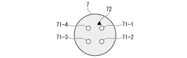
- 2 is a diagram showing an example of a cross section of a transmission line fiber according to the first embodiment;
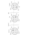
- FIG. 4 is a diagram for explaining the correspondence of core numbers in a transmission link according to the first embodiment.
- FIG. FIG. 11 is a configuration diagram of an optical transmission system according to a second embodiment.
- 11A and 11B are diagrams illustrating an example of a cross section of a transmission line fiber according to a second embodiment.
- FIG. 11 is a diagram illustrating a connection configuration between an optical receiver and a signal processing unit according to a second embodiment.
- 11A and 11B are diagrams illustrating results of a transmission experiment of the optical transmission system according to the first embodiment.
- Optical transmitter 1-n (n is an integer such that 1 ⁇ n ⁇ N) has the function of converting a bit string b-n, which is an electrical signal, into an optical signal.
- Optical transmitter 1-n generally includes a light source, a signal processing unit, a digital-to-analog (DA) converter, and an optical waveguide circuit.
- the optical waveguide circuit integrates optical modulation, optical amplification, optical multiplexing/demultiplexing, and optical monitoring functions. In this embodiment, a description of these components of optical transmitter 1-n is omitted.
- Figure 2 is a schematic diagram showing an example of a cross section of a transmission fiber 7.
- the four cores 71 of the transmission fiber 7 are identified as cores 71-1 to 71-4 by markers 72.
- the core 71 with core number n (n is an integer such that 1 ⁇ n ⁇ N) is core 71-n.
- These four cores 71 can also be said to be arranged in a circular ring shape at equal angular intervals from the center of the transmission fiber 7.
- the core numbers are assigned in ascending order, starting from the core 71 closest to the marker 72 to the core 71 adjacent to that core 71.
- FIG. 3 is a diagram for explaining the correspondence of core numbers from transmission line fiber 7-(k-1) to transmission line fiber 7-(k+1) in transmission link 6 (k is an integer such that 1 ⁇ k ⁇ K).
- the diagram shows cross sections of transmission line fiber 7-(k-1) to transmission line fiber 7-(k+1).
- Transmission line fiber 7-(k-1) and transmission line fiber 7-k are connected at connection point 8-(k-1), and transmission line fiber 7-k and transmission line fiber 7-(k+1) are connected at connection point 8-k.
- the angle rotation is not limited to the above-mentioned form, and when the angle rotation of the transmission fiber 7 with respect to a predetermined reference is (2 ⁇ /N) ⁇ p (p is an integer such that 0 ⁇ p ⁇ N-1), the angle rotation of each of the N transmission fibers 7 connected in succession by (N-1) connection points 8 may be set so that p is not used twice.
- the predetermined reference is one of the N transmission fibers 7, p of that transmission fiber 7 is 0. For example, in the case of FIG.
- the angle rotations of the transmission fibers 7-2, 7-3, and 7-4 are (2 ⁇ /N) ⁇ 1, (2 ⁇ /N) ⁇ 2, and (2 ⁇ /N) ⁇ 3, respectively, but may be (2 ⁇ /N) ⁇ 3, (2 ⁇ /N) ⁇ 1, or (2 ⁇ /N) ⁇ 2.
- the optical signal propagating through each core 71 makes a circuit of the four cores 71-1 to 71-4, although in a different order, each time it passes through the four transmission line fibers 7, and therefore the skew between the cores is cancelled out.
- the relative group velocity per unit distance of the core 71-i i is an integer between 1 and N
- ⁇ i the optical signal propagating through the core 71-i is subjected to a relative skew of an amount ⁇ i ⁇ l at a point of distance l.
- the total length of the transmission link formed by the transmission line fibers 7-1 to 7-N is L.
- the relative skew after propagating the distance L is expressed by the following formula (1) in all spatial channels.
- the effective relative group velocity per unit distance in this configuration is the average of the original relative group velocities of all the cores 71, and is the same regardless of the spatial channel. Therefore, the relative inter-core skew felt by the optical signal propagating through each core 71 is effectively zero. This makes it possible to reduce the pulse spread ⁇ .
- connection points 8 are realized by fusion splicing, mechanical splicing, or connector connection.
- connection method that does not involve an interface device between the multicore fiber and the single-mode fiber, such as fan-in/fan-out, it is possible to avoid excess loss due to device insertion.
- the second embodiment aims to reduce the number of adjacent cores affected by IXT and reduce the scale of MIMO type signal processing.
- FIG. 4 is a diagram showing the configuration of an optical transmission system 11 according to the second embodiment.
- the optical transmission system 11 shown in FIG. 4 differs from the optical transmission system 10 shown in FIG. 1 in that it has a transmission link 6a instead of the transmission link 6, and a signal processing unit 5a instead of the signal processing unit 5.
- the transmission link 6a is configured by connecting K transmission fiber 7a (K is an integer of 2 or more) having the same characteristics and the same length.
- the transmission fiber 7a is a multicore fiber having N cores.
- the K transmission fiber 7a are referred to as transmission fiber 7a-1 to 7a-K.
- the upstream transmission fiber 7a-k and the transmission fiber 7a-(k+1) on the downstream side are connected via a connection point 8-k in a state of being rotated by an angle of 2 ⁇ /N (k is an integer of 1 ⁇ k ⁇ K).
- the angle rotation of the transmission fiber 7a with respect to a predetermined reference is (2 ⁇ /N) ⁇ p (p is an integer of 0 to N-1)
- the angle rotation of each of the N transmission fiber 7a connected in succession by (N-1) connection points 8 may be set so that p is not used in duplicate.
- FIG. 5 is a schematic diagram showing an example of a cross section of the transmission line fiber 7a of the second embodiment.
- the transmission line fiber 7a used in the second embodiment is characterized in that it is a multicore fiber in which cores 71-1 to 71-6 are arranged on a ring. Core numbers are assigned in ascending order from the core 71 closest to the marker 72 to the core 71 adjacent to that core 71.
- IXT from the cores 71 adjacent to the left and right is dominant.
- IXT from cores 71-1 and 71-3 is dominant.
- the received signal processing unit 51a receives the analog electrical signals E1 to E3 from each of the optical receivers 4-1 to 4-3.
- the received signal processing unit 51a compensates for the IXT of the analog electrical signal E2 by MIMO type signal processing using the waveform information obtained from the analog electrical signal E1 and the waveform information obtained from the analog electrical signal E3, and obtains the bit string b-2 from the signal after IXT compensation.
- the received signal processing unit 51a-2 for detecting the bit string b-2 is shown, but the same applies to the received signal processing units 51a other than the received signal processing unit 51a-2.
- the distance of the transmission link that enables the reduction of the pulse spread ⁇ in the first embodiment is limited.
- the two cores are core #1 and core #2.
- the relative group velocity per unit distance of core #1 is ⁇ 1
- the relative group velocity per unit distance of core #2 is - ⁇ 1.
- the coupling coefficient between cores is h
- the value of the inter-core crosstalk experienced by a signal after propagating a distance L corresponding to the transmission distance of one span can be approximated to hL (see, for example, Reference 1).
- One span corresponds to the distance between relay amplifiers.
- the relative skew of the signals propagating through core #1 and core #2 becomes zero at the point of distance L.
- the relative skew with the signal light also becomes zero at the point of distance L.
- the inter-core crosstalk generated at other points causes a propagation delay of up to ⁇ 1 ⁇ L when propagating the distance L, and the relative skew after one span transmission does not become zero.
- this inter-core crosstalk does not cause any further relative delay. Therefore, the power of the signal light and the inter-core crosstalk always exists within the time width of 2 ⁇ 1 ⁇ L.
- M-order crosstalk is inter-core crosstalk that has transited between cores M times. It is not guaranteed that M-order crosstalk satisfies the condition that the relative inter-core skew is 0, and the relative inter-core skew is determined by the place where it occurs (where phase matching occurs) and the order of M. In other words, M-order crosstalk of second or higher order does not necessarily exist within the time width of 2 ⁇ 1 ⁇ L, and therefore becomes a factor that increases the pulse spread ⁇ .
- the distance at which such a phenomenon occurs is the distance at which the crosstalk approximation value (hL) 2 of the second-order crosstalk is of the same order as the first-order crosstalk approximation value hL, and therefore is L that satisfies hL ⁇ (hL) 2 , i.e., hL ⁇ 1.
- the transmission link distance is limited by 1/h.
- a four-core step-type multicore fiber arranged in a square lattice has a coupling coefficient of approximately -40 to -30 dB/km in the 1.5 ⁇ m band.
- the distance of the transmission link in the third embodiment calculated from this corresponds to 1,000 to 10,000 km.
- Each transmission fiber 7 is a multi-core fiber having a length of 5 km and four cores.
- the transmission fibers 7 were fusion-spliced with an angle rotation of ⁇ /2, and the pulse response spread was measured.
- Figure 7 shows the results of pulse broadening versus transmission distance. As shown in Figure 7, the pulse broadening is constant regardless of the transmission distance, indicating that the relative skew of the optical signal and the IXT component is offset by the periodic core swapping.
- the optical transmission system has a plurality of optical transmitters, a spatial multiplexing unit, an optical transmission path, a spatial multiplexing/demultiplexing unit, a plurality of optical receivers, and a signal processing unit.
- Each of the plurality of optical transmitters transmits an optical signal.
- the spatial multiplexing unit multiplexes the plurality of optical signals transmitted from each of the plurality of optical transmitters into a spatial multiplexed signal.
- the optical transmission path transmits the spatial multiplexed signal.
- the spatial multiplexing/demultiplexing unit splits the spatial multiplexed signal into a plurality of optical signals.
- the plurality of optical receivers convert each of the plurality of optical signals split by the spatial multiplexing/demultiplexing unit into an analog electrical signal.
- the signal processing unit compensates for crosstalk for each of the plurality of analog electrical signals by using another analog electrical signal.
- the signal processing unit may compensate for crosstalk by using waveform information obtained from an analog electrical signal converted from an optical signal transmitted through a core and an adjacent core in the multicore fiber.
- the distance of the optical transmission path may be equal to or less than the reciprocal of the coupling coefficient h between the cores.
- Optical transmitter 2 Spatial multiplexer 3
- Optical receiver 5 5a Signal processing unit 6, 6a Transmission link 7, 7-1 to 7-K, 7a, 7a-1 to 7a-K Transmission line fiber 8-1 to 8-(K-1) 10, 11
Landscapes
- Engineering & Computer Science (AREA)
- Computer Networks & Wireless Communication (AREA)
- Signal Processing (AREA)
- Physics & Mathematics (AREA)
- Electromagnetism (AREA)
- Optical Fibers, Optical Fiber Cores, And Optical Fiber Bundles (AREA)
- Mechanical Coupling Of Light Guides (AREA)
- Manufacture, Treatment Of Glass Fibers (AREA)
Priority Applications (2)
| Application Number | Priority Date | Filing Date | Title |
|---|---|---|---|
| PCT/JP2022/047827 WO2024142135A1 (ja) | 2022-12-26 | 2022-12-26 | 光伝送路、光伝送システム、及び、光伝送方法 |
| JP2024566927A JPWO2024142135A1 (https=) | 2022-12-26 | 2022-12-26 |
Applications Claiming Priority (1)
| Application Number | Priority Date | Filing Date | Title |
|---|---|---|---|
| PCT/JP2022/047827 WO2024142135A1 (ja) | 2022-12-26 | 2022-12-26 | 光伝送路、光伝送システム、及び、光伝送方法 |
Publications (1)
| Publication Number | Publication Date |
|---|---|
| WO2024142135A1 true WO2024142135A1 (ja) | 2024-07-04 |
Family
ID=91716852
Family Applications (1)
| Application Number | Title | Priority Date | Filing Date |
|---|---|---|---|
| PCT/JP2022/047827 Ceased WO2024142135A1 (ja) | 2022-12-26 | 2022-12-26 | 光伝送路、光伝送システム、及び、光伝送方法 |
Country Status (2)
| Country | Link |
|---|---|
| JP (1) | JPWO2024142135A1 (https=) |
| WO (1) | WO2024142135A1 (https=) |
Citations (3)
| Publication number | Priority date | Publication date | Assignee | Title |
|---|---|---|---|---|
| JP2020101809A (ja) * | 2015-10-08 | 2020-07-02 | 住友電気工業株式会社 | マルチコア光ファイバ、マルチコア光ファイバケーブルおよび光ファイバ伝送システム |
| WO2022003751A1 (ja) * | 2020-06-29 | 2022-01-06 | 日本電信電話株式会社 | マルチコアファイバ、光伝送システム、および、光伝送方法 |
| WO2022176978A1 (ja) * | 2021-02-19 | 2022-08-25 | 株式会社フジクラ | 光入出力装置 |
-
2022
- 2022-12-26 WO PCT/JP2022/047827 patent/WO2024142135A1/ja not_active Ceased
- 2022-12-26 JP JP2024566927A patent/JPWO2024142135A1/ja active Pending
Patent Citations (3)
| Publication number | Priority date | Publication date | Assignee | Title |
|---|---|---|---|---|
| JP2020101809A (ja) * | 2015-10-08 | 2020-07-02 | 住友電気工業株式会社 | マルチコア光ファイバ、マルチコア光ファイバケーブルおよび光ファイバ伝送システム |
| WO2022003751A1 (ja) * | 2020-06-29 | 2022-01-06 | 日本電信電話株式会社 | マルチコアファイバ、光伝送システム、および、光伝送方法 |
| WO2022176978A1 (ja) * | 2021-02-19 | 2022-08-25 | 株式会社フジクラ | 光入出力装置 |
Non-Patent Citations (1)
| Title |
|---|
| LUÍS RUBEN S., RADEMACHER GEORG, PUTTNAM BENJAMIN J., AWAJI YOSHINARI, WADA NAOYA: "Long distance crosstalk-supported transmission using homogeneous multicore fibers and SDM-MIMO demultiplexing", OPTICS EXPRESS, OPTICAL SOCIETY OF AMERICA, US, vol. 26, no. 18, 3 September 2018 (2018-09-03), US, pages 24044, XP093187580, ISSN: 1094-4087, DOI: 10.1364/OE.26.024044 * |
Also Published As
| Publication number | Publication date |
|---|---|
| JPWO2024142135A1 (https=) | 2024-07-04 |
Similar Documents
| Publication | Publication Date | Title |
|---|---|---|
| Klaus et al. | The role of parallelism in the evolution of optical fiber communication systems | |
| Mizuno et al. | 32-core dense SDM unidirectional transmission of PDM-16QAM signals over 1600 km using crosstalk-managed single-mode heterogeneous multicore transmission line | |
| Sakaguchi et al. | Space division multiplexed transmission of 109-Tb/s data signals using homogeneous seven-core fiber | |
| CN103095373B (zh) | 基于模分复用的自相干光纤通信系统 | |
| WO2017123489A1 (en) | Optical spatial multiplexing usable at short reach | |
| WO2022003751A1 (ja) | マルチコアファイバ、光伝送システム、および、光伝送方法 | |
| JP2013214852A (ja) | 光ファイバ伝送システム及び光ファイバ伝送方法 | |
| Shukla et al. | Joint WDM and OAM mode group multiplexed transmission over conventional multimode fiber | |
| Gao et al. | Prototype of DSP-free IM/DD MDM transceiver for datacenter interconnection | |
| RU2739069C1 (ru) | Устройство для организации перегонной связи и способ организации перегонной связи (варианты) | |
| JP5524900B2 (ja) | 光ファイバ伝送システム及び光受信装置 | |
| CN112953639A (zh) | 一种基于低串扰少模-多芯光纤的量子与经典融合系统和方法 | |
| WO2024142135A1 (ja) | 光伝送路、光伝送システム、及び、光伝送方法 | |
| US20260031907A1 (en) | Signal processing apparatus, signal processing method and program | |
| CN112702119B (zh) | 一种基于光电融合的差分模式群时延补偿方法和系统 | |
| Zhang et al. | High-speed free-space optical communication using mode demultiplexers and coherent beam combining | |
| CN114598391B (zh) | 一种基于少模光纤的远端真时延波束赋形实现方法 | |
| Suzuki et al. | High-Capacity and Ultra-Long-Haul Transmission over Transoceanic Distances Using Coupled and Uncoupled 4-Core Fibers with Standard Cladding Diameter | |
| Suzuki et al. | Ultra-high capacity optical transmission over 10-Pbit/s based on optical space division multiplexing technologies | |
| JP7376827B2 (ja) | 光伝送システム、光伝送装置及び光伝送方法 | |
| JP5658610B2 (ja) | 光ファイバ伝送システム及び光受信装置 | |
| Nakamura et al. | Technologies for optical submarine cables: Past present & future | |
| CN119628740B (zh) | 一种通信设备、基站及通信系统 | |
| EP3440785B1 (en) | Apparatus and method for transmitting an optical transmission signal via separated free-space optical paths | |
| Rjeb et al. | Partial & full MIMO for orbital angular momentum mode group division multiplexing via optical fibers |
Legal Events
| Date | Code | Title | Description |
|---|---|---|---|
| 121 | Ep: the epo has been informed by wipo that ep was designated in this application |
Ref document number: 22969929 Country of ref document: EP Kind code of ref document: A1 |
|
| WWE | Wipo information: entry into national phase |
Ref document number: 2024566927 Country of ref document: JP |
|
| NENP | Non-entry into the national phase |
Ref country code: DE |
|
| 122 | Ep: pct application non-entry in european phase |
Ref document number: 22969929 Country of ref document: EP Kind code of ref document: A1 |