WO2024135829A1 - アーク溶接方法 - Google Patents
アーク溶接方法 Download PDFInfo
- Publication number
- WO2024135829A1 WO2024135829A1 PCT/JP2023/046158 JP2023046158W WO2024135829A1 WO 2024135829 A1 WO2024135829 A1 WO 2024135829A1 JP 2023046158 W JP2023046158 W JP 2023046158W WO 2024135829 A1 WO2024135829 A1 WO 2024135829A1
- Authority
- WO
- WIPO (PCT)
- Prior art keywords
- welding
- period
- welding wire
- extension length
- wire
- Prior art date
- Legal status (The legal status is an assumption and is not a legal conclusion. Google has not performed a legal analysis and makes no representation as to the accuracy of the status listed.)
- Ceased
Links
Images


Classifications
-
- B—PERFORMING OPERATIONS; TRANSPORTING
- B23—MACHINE TOOLS; METAL-WORKING NOT OTHERWISE PROVIDED FOR
- B23K—SOLDERING OR UNSOLDERING; WELDING; CLADDING OR PLATING BY SOLDERING OR WELDING; CUTTING BY APPLYING HEAT LOCALLY, e.g. FLAME CUTTING; WORKING BY LASER BEAM
- B23K9/00—Arc welding or cutting
- B23K9/12—Automatic feeding or moving of electrodes or work for spot or seam welding or cutting
-
- B—PERFORMING OPERATIONS; TRANSPORTING
- B23—MACHINE TOOLS; METAL-WORKING NOT OTHERWISE PROVIDED FOR
- B23K—SOLDERING OR UNSOLDERING; WELDING; CLADDING OR PLATING BY SOLDERING OR WELDING; CUTTING BY APPLYING HEAT LOCALLY, e.g. FLAME CUTTING; WORKING BY LASER BEAM
- B23K9/00—Arc welding or cutting
- B23K9/06—Arrangements or circuits for starting the arc, e.g. by generating ignition voltage, or for stabilising the arc
- B23K9/067—Starting the arc
-
- B—PERFORMING OPERATIONS; TRANSPORTING
- B23—MACHINE TOOLS; METAL-WORKING NOT OTHERWISE PROVIDED FOR
- B23K—SOLDERING OR UNSOLDERING; WELDING; CLADDING OR PLATING BY SOLDERING OR WELDING; CUTTING BY APPLYING HEAT LOCALLY, e.g. FLAME CUTTING; WORKING BY LASER BEAM
- B23K9/00—Arc welding or cutting
-
- B—PERFORMING OPERATIONS; TRANSPORTING
- B23—MACHINE TOOLS; METAL-WORKING NOT OTHERWISE PROVIDED FOR
- B23K—SOLDERING OR UNSOLDERING; WELDING; CLADDING OR PLATING BY SOLDERING OR WELDING; CUTTING BY APPLYING HEAT LOCALLY, e.g. FLAME CUTTING; WORKING BY LASER BEAM
- B23K9/00—Arc welding or cutting
- B23K9/095—Monitoring or automatic control of welding parameters
-
- B—PERFORMING OPERATIONS; TRANSPORTING
- B23—MACHINE TOOLS; METAL-WORKING NOT OTHERWISE PROVIDED FOR
- B23K—SOLDERING OR UNSOLDERING; WELDING; CLADDING OR PLATING BY SOLDERING OR WELDING; CUTTING BY APPLYING HEAT LOCALLY, e.g. FLAME CUTTING; WORKING BY LASER BEAM
- B23K9/00—Arc welding or cutting
- B23K9/12—Automatic feeding or moving of electrodes or work for spot or seam welding or cutting
- B23K9/124—Circuits or methods for feeding welding wire
- B23K9/125—Feeding of electrodes
Definitions
- the present invention relates to an arc welding method.
- Patent Document 1 discloses an arc start control method for welding by moving a welding torch attached to a manipulator of a welding robot.
- the welding torch is moved in the welding wire feed direction at the welding start position to bring the wire tip closer to the workpiece. Then, when it is determined that the wire tip has come into contact with the workpiece, the robot is moved backward in the direction opposite to the wire feed direction to generate an arc.
- the welding torch is brought close to the workpiece by the welding robot, causing the welding wire to come into contact with the workpiece and generating an arc.
- the welding wire may deform, which may result in an incorrect arc start.
- the present invention was made in consideration of these points, and its purpose is to enable stable arc starting while suppressing deformation of the welding wire.
- the first aspect is an arc welding method in which a welding wire is fed toward a workpiece and an arc is generated between the welding wire and the workpiece to weld the workpiece, and the welding period from the start of welding to the end of welding includes a start period and a main welding period after the start period, and includes the steps of feeding the welding wire at a predetermined feed rate during the start period, generating an arc between the welding wire and the workpiece after the tip of the welding wire comes into contact with the workpiece and shorts out, and feeding the welding wire at a feed rate higher than the feed rate during the start period during the main welding period, and the extension length of the welding wire at the time when the tip of the welding wire comes into contact with the workpiece and shorts out immediately before the generation of an arc at the start of welding during the start period is shorter than the extension length of the welding wire during the main welding period.
- the extension length of the welding wire at the start of welding during the start period is shortened, so that the arc start can be performed stably while suppressing deformation of the welding wire.
- the start period is a transition period from the start for the arc start to the actual welding period.
- the second aspect is the arc welding method of the first aspect, in which the extension length of the welding wire at the start of welding in the start period is 30% to 80% of the extension length of the welding wire in the main welding period.
- the welding period includes an end period that follows the main welding period, and the extension length of the welding wire at the end of welding in the end period is equal to or less than the extension length of the welding wire at the start of welding in the start period.
- a fourth aspect is an arc welding method according to the first or second aspect, in which the welding period includes an end period that follows the main welding period, and includes a step of feeding the welding wire so that the extension length of the welding wire at the end of the end period is the same as the extension length of the welding wire in the main welding period, and a step of feeding the welding wire in the reverse direction so that, after the end period, the extension length of the welding wire is equal to or less than the extension length of the welding wire at the start of welding in the start period.
- the welding wire is reversed after the end of the end period to shorten the welding wire extension length, thereby preventing problems such as a touch start from occurring when the next welding operation begins.
- the workpiece in the arc welding method of the first or second aspect, is made of mild steel or a material having a higher electrical resistance than mild steel.
- the amount of deposition of the welding wire can be ensured by increasing the extension length of the welding wire during this welding period.
- the extension length of the welding wire at the time when the tip of the welding wire comes into contact with the workpiece and short-circuits immediately before the generation of an arc at the start of welding in the starting period is shorter than the extension length of the welding wire in the transition period from the starting period to the main welding period and in which the feed speed or the average feed speed increases.
- the extension length of the welding wire during the main welding period when a molten pool is formed and the molten state is stable, is made longer than the extension length of the welding wire at the start of welding in the starting period (the point at which the tip of the welding wire comes into contact with the workpiece and shorts out), thereby increasing the amount of welding wire deposition and ensuring a stable, high amount of deposition.
- the deposition amount of the welding wire before the main welding period can be smoothly increased, ensuring a stable, high deposition amount, and more reliably ensuring a stable, high deposition amount from the start of the main welding period.
- FIG. 1 is a schematic diagram of an arc welding device according to the present embodiment.
- FIG. 2 is a diagram showing waveforms of current, voltage, and feed speed in pulse welding, as well as extension lengths and teaching points.
- FIG. 3 is a diagram showing waveforms of current, voltage, and feed speed, extension length, and teaching points when an arc start failure occurs.
- FIG. 4 is a diagram showing an example of an arc start failure.
- FIG. 5 is a diagram showing waveforms of current, voltage, and feed speed, extension length, and teaching points in pulse welding in the present modified example 1.
- FIG. 6 is a diagram showing waveforms of current, voltage, and feed speed, extension length, and teaching points in pulse welding in the present modified example 2.
- FIG. 1 is a schematic diagram of an arc welding device according to the present embodiment.
- FIG. 2 is a diagram showing waveforms of current, voltage, and feed speed in pulse welding, as well as extension lengths and teaching points.
- FIG. 3 is a diagram showing waveforms
- FIG. 7 is a diagram showing waveforms of current, voltage, and feed speed, extension length, and teaching points in pulse welding in the third modified example.
- FIG. 8 is a diagram showing waveforms of current, voltage, and feed speed, extension length, and teaching points in pulse welding in the fourth modified example.
- FIG. 9 is a diagram showing waveforms of current, voltage, and feed speed, extension length, and teaching points in short-circuit welding in the fifth modified example.
- FIG. 10 is a diagram showing waveforms of current, voltage, and feed speed, extension length, and teaching points during short-circuit welding when forward/reverse feed control is performed in this modification 6.
- the arc welding device 1 welds the workpiece 5 by generating an arc 3 between a welding wire 2, which is a consumable electrode, and the workpiece 5.
- the workpiece 5 is made of mild steel or a material with a higher electrical resistance than mild steel (e.g., stainless steel).
- the welding wire 2 is wound around a wire reel 4.
- the wire cast diameter of the welding wire 2 as the free diameter pulled out from the wire reel 4 (the diameter of the expanded loop of the welding wire 2 when it is cut into two or three turns and placed on a flat surface without restraint) is preferably adjusted to ⁇ 2000 mm or more by installing a wire straightener (a device that straightens the wire curvature, which is the wire tendency of the welding wire 2, to a constant state) not shown in the figure in the feed path.
- a wire straightener a device that straightens the wire curvature, which is the wire tendency of the welding wire 2, to a constant state
- the arc welding device 1 has a welding torch 10, a wire feeder 15, a robot 20, a control unit 25, and a power source (not shown).
- a tip 11 is provided at the tip of the welding torch 10. The tip 11 supplies power to the welding wire 2.
- the wire feeder 15 feeds the welding wire 2 at a predetermined feed speed based on a signal from the control unit 25.
- the wire feeder 15 can also alternate between forward feed, which feeds the welding wire 2 in the direction of the workpiece 5, and reverse feed, which feeds the welding wire 2 in the opposite direction to the forward feed, based on a signal from the control unit 25.
- the robot 20 has multiple joints.
- a welding torch 10 is attached to the tip of the robot 20.
- the robot 20 moves the position of the welding torch 10 relative to the workpiece 5.
- the control unit 25 controls the operation of the robot 20 and the wire feed unit 15.
- the control unit 25 moves the welding torch 10 along the welding direction of the workpiece 5 by giving current commands to the motors (not shown) of each axis of the robot 20.
- the control unit 25 controls the feed speed of the welding wire 2 according to a preset set current of the welding current.
- the feed speed and the welding current are correlated with each other. More specifically, the average welding speed (also called the feed amount) as a moving average and the average welding current (also called the set current), which is the average current as a moving average, are correlated with each other.
- the arc welding device 1 supplies a current between the welding wire 2 and the workpiece 5. This generates an arc 3 between the welding wire 2 and the workpiece 5, and the heat of the arc 3 melts the tip of the welding wire 2 and a part of the workpiece 5.
- the molten welding wire 2 turns into molten droplets and drips onto the workpiece 5, forming a molten pool together with the part of the workpiece 5 melted by the heat of the arc 3.
- the welding torch 10 moves along the welding direction of the workpiece 5. As the welding torch 10 moves, a bead 6 (see Figure 2) is formed on the workpiece 5, and the workpiece 5 is welded.
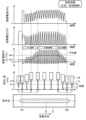
- Figure 2 shows the waveforms of current, voltage, and feed speed in pulse welding, as well as the extension length and teaching points.
- the vertical axis shows the welding current A, welding voltage V, and feed speed WF
- the horizontal axis shows time.
- the arc welding device 1 supplies a welding current A and a welding voltage V to the welding wire 2.
- the pulse waveform of the welding current A is a pulse-like waveform and includes a peak current period during which the welding current A is a peak current, and a base current period during which the welding current A is a base current.
- the peak current and base current may change in response to the switching of pulses.
- the feed speed WF and the welding current A are correlated with each other, and the peak current and base current of the welding current A change in response to the change in the feed speed WF when the pulses are switched.
- the peak current and base current of the welding current A change in response to the average welding current Aav, which is the average current as a moving average (also called the set current) when the pulses are switched.
- the feed speed WF of the welding wire 2 is set based on the magnitude of the average welding current Aav as the average welding current.
- a periodic droplet transfer state is obtained by periodically repeating a peak current period and a base current period at a predetermined pulse frequency.
- an average welding current Aav of 200 A is applied to the welding wire 2 as the average welding current (also called the set current), which is the average current as a moving average.
- the arc welding device 1 sets the feed speed of the welding wire 2 based on the magnitude of the average welding current Aav as the set moving average.
- Various pulse parameters that configure the DC pulse waveform are set based on the feed speed of the welding wire 2.
- a welding start point P1 and a welding end point P2 are set on the workpiece 5.
- the arc welding device 1 performs pulse welding while moving the welding torch 10 in the welding direction from the welding start point P1 to the welding end point P2 during the welding period from the start of welding to the end of welding.
- t1 indicates the time when the feeding operation of the welding wire 2 is started.
- the feeding operation of the welding wire 2 from time t1 to time t4 is performed in a state where the movement of the welding torch 10 in the welding direction is stopped and the welding torch 10 is kept waiting above the welding start point P1.
- the operation of supplying the welding wire 2 during the period from time t1 to time t2 and during the start period from time t2 to time t4 described below is performed while the welding torch 10 is waiting to move in the welding direction above the welding start point P1.
- the welding wire 2 is constantly fed at the first feed speed WF1.
- the welding period includes a start period, a main welding period, and an end period.
- the start period is the period from when welding starts at the welding start point P1 of the workpiece 5 until a molten pool is formed on the workpiece 5.
- the start period is the transition period from the start for the arc start to the main welding period.
- the start period is the period from time t2 to time t4.
- t2 indicates the time when the tip of the welding wire 2 comes into contact with the workpiece 5 and shorts out. From time t2 to time t3, an arc 3 is generated between the welding wire 2 and the workpiece 5, and the welding wire 2 is constantly fed at a first feed speed WF1.
- the feed speed of the welding wire 2 is gradually increased from the first feed speed WF1 to the second feed speed WF2.
- the second feed speed WF2 is greater than the first feed speed WF1.
- the start period is changed to the main welding period.
- the main welding period is the period from time t4 to time t5.
- pulse welding is performed by the robot 20 while moving the welding torch 10 in the welding direction from the welding start point P1 to the welding end point P2 of the workpiece 5.
- the welding wire 2 is fed at a constant rate at the second feed speed WF2.
- the welding torch 10 moves to the welding end point P2, and then the main welding period transitions to the end period.
- the end period is the period from time t5 to time t6.
- the feeding operation of the welding wire 2 from time t5 to time t6 is performed with the welding torch 10 stopping its movement in the welding direction and waiting above the welding end point P2.
- the end period is the period until the supply speed of the welding wire 2 stops at the welding end point P2 of the workpiece 5. Specifically, from time t5 to time t6, the feed speed of the welding wire 2 is gradually reduced from the second feed speed WF2 to zero. From time t6 to time t7, the feed operation of the welding wire 2 stops, and the extension length of the welding wire 2 at time t7 becomes shorter.
- the distance between the tip of the tip 11 of the welding torch 10 and the surface of the workpiece 5 (the surface of the workpiece 5 facing the tip 11) is kept constant during the start period (t2-t4), main welding period (t4-t5), and end period (t5-t6), and the extension length of the welding wire 2, which is the length by which the welding wire 2 protrudes from the tip of the tip 11, is set to a long extension length Ex2 of, for example, 25 mm.
- the extension length Ex1 of the welding wire 2 at the start of welding in the start period (time t2 when the tip of the welding wire 2 comes into contact with the workpiece 5 and short-circuits) is set to be shorter than the extension length Ex2 of the welding wire 2 in the main welding period (Ex1 ⁇ Ex2).
- the extension length Ex1 of the welding wire 2 at the start of welding in the start period (time t2 when the tip of the welding wire 2 comes into contact with the workpiece 5 and short-circuits) is set to be shorter than the extension length Ex2 of the welding wire 2 in the main welding period.
- the arc welding device 1 adjusts the distance between the tip of the tip 11 of the welding torch 10 and the surface of the workpiece 5 (the surface of the workpiece 5 facing the tip 11) by moving the welding torch 10 up and down using the robot 20.
- the extension length of the welding wire 2 is set by this distance.
- the extension length of the welding wire 2 at the point when the tip of the welding wire 2 comes into contact with the workpiece 5 and shorts out immediately before the generation of an arc at the start of welding in the starting period is defined as the first extension length Ex1. Also, the extension length of the welding wire 2 during this welding period is defined as the second extension length Ex2.
- the height position of the welding torch 10 is adjusted so that the first extension length Ex1 is shorter than the second extension length Ex2.
- the first extension length Ex1 is set to 15 mm and the second extension length Ex2 is set to 25 m.
- the first extension length Ex1 during the start period may be changed as appropriate depending on the wire diameter of the welding wire 2.
- the first extension length Ex1 of the welding wire 2 at the start of welding in the starting period is 30% to 80% of the second extension length Ex2 of the welding wire 2 in the main welding period.
- the second extension length Ex2 during the main welding period is set to 20 to 30 mm
- the first extension length Ex1 during the start period is set to 12 to 15 mm
- the extension length ratio Ex1/Ex2 during the start period is set to 40% to 75%.
- the welding wire 2 is fed at a constant first feed speed WF1 at the welding start point P1.
- the height of the welding torch 10 is gradually raised so as to increase the distance from the surface of the workpiece 5, thereby gradually increasing the extension length of the welding wire 2 from the first extension length Ex1 to the second extension length Ex2.
- the extension length of the welding wire 2 becomes the second extension length Ex2, which is longer (greater) than the first extension length Ex1.
- the feed speed of the welding wire 2 is gradually increased from the first feed speed WF1 to the second feed speed WF2, and the actual welding period begins. During this period, the extension length of the welding wire 2 is constant at the second extension length Ex2.
- the extension length of the welding wire 2 at the point when the tip of the welding wire 2 comes into contact with the workpiece 5 and shorts out immediately before the arc is generated at the start of welding during the start period is shorter than the extension length of the welding wire 2 during the transition period from the start period to the main welding period when the feed speed is increasing.
- the height of the welding torch 10 is kept constant, and the welding torch 10 is moved in the welding direction from the welding start point P1 to the welding end point P2, and then the end period begins.
- the extension length of the welding wire 2 is constant at the second extension length Ex2, and the feed speed of the welding wire 2 is constant at the second feed speed WF2.
- the welding wire 2 is gradually decreased from the second feed speed WF2 to zero.
- the height of the welding torch 10 is gradually lowered so as to decrease the distance from the surface of the workpiece 5, thereby gradually decreasing the extension length of the welding wire 2 from the second extension length Ex2 to the first extension length Ex1 or less.
- the extension length of the welding wire 2 at the end of welding in the end period is shorter than the extension length of the welding wire 2 in the main welding period, and is equal to or shorter than the extension length of the welding wire 2 at the start of welding in the start period.
- the extension length of the welding wire 2 at the end of welding in the end period is also 15 mm.
- the extension length of the welding wire 2 at the end of welding in the end period may be reduced to 5 mm.
- the extension length of the welding wire 2 at the start of welding in the start period shorter than the extension length of the welding wire 2 in the main welding period and equal to or less than the extension length of the welding wire 2 at the start of welding in the start period, it is possible to stably perform an arc start while suppressing deformation of the welding wire 2.
- the extension length of the welding wire 2 longer in the main welding period it is possible to ensure the deposition amount of the welding wire 2.
- the resistance value of the welding wire 2 at the extension length can be relatively lowered and deformation of the welding wire can be suppressed, thereby achieving both a stable arc start and a sufficient deposition amount of the welding wire 2.
- the amount of deposition of the welding wire 2 can be increased and a stable high amount of deposition can be ensured by making the extension length of the welding wire 2 longer during the main welding period, when a molten pool is formed and the molten state is stable, than the extension length of the welding wire 2 at the start of welding in the starting period.
- the welding wire 2 protruding from the tip 11 can be set to an appropriate extension length, and problems such as a touch start can be prevented from occurring when the next welding begins.
- the extension length of the welding wire 2 can be made longer during the main welding period, when a molten pool is formed and the molten state is stable, than the extension length of the welding wire 2 at the start of welding in the starting period (the point at which the tip of the welding wire 2 comes into contact with the workpiece 5 and shorts out), the deposition amount of the welding wire 2 can be increased and a stable high deposition amount can be ensured.
- the deposition amount of the welding wire 2 before the main welding period can be smoothly increased, ensuring a stable high deposition amount, and more reliably ensuring a stable high deposition amount from the start of the main welding period.
- t1 indicates the time when the feeding operation of the welding wire 2 is started.
- the feeding operation of the welding wire 2 from time t1 to time t3 is performed with the welding torch 10 waiting above the welding start point P1 in the welding direction.
- the welding wire 2 is fed at a constant first feeding speed WF1.
- the start period is the period from time t2 to time t3.
- t2 indicates the time when the tip of the welding wire 2 comes into contact with the workpiece 5 and shorts out.
- time t2 and time t3 an arc 3 is generated between the welding wire 2 and the workpiece 5, and the feed speed of the welding wire 2 is gradually increased from the first feed speed WF1 to the second feed speed WF2.
- the height of the welding torch 10 is gradually raised so as to increase the distance from the surface of the workpiece 5, thereby gradually increasing the extension length of the welding wire 2 from the first extension length Ex1 to the second extension length Ex2.
- the feed speed of the welding wire 2 reaches the second feed speed WF2, and then the start period transitions to the main welding period.
- the feed speed of the welding wire 2 is increased and the extension length of the welding wire 2 is made longer than the extension length of the welding wire 2 at the start of welding during the start period (time t2 when the tip of the welding wire 2 comes into contact with the workpiece 5 and short-circuits), thereby shortening the cycle time during the start period and making it possible to stably shorten the overall welding time.
- the main welding period is the period from time t3 to time t4.
- the end period is the period from time t4 to time t5.
- Time t6 indicates the state after the end period when the extension length of the welding wire 2 has become shorter.
- the welding start point is P1 and the welding end point is P4.
- a teaching point P2 is set at a position away from the welding start point P1 on the downstream side in the welding direction.
- a teaching point P3 is set at a position away from the welding end point P4 on the upstream side in the opposite direction to the welding direction.
- t1 indicates the time when the feeding operation of the welding wire 2 is started.
- the feeding operation of the welding wire 2 from time t1 to time t2 is performed while the welding torch 10 is waiting to move in the welding direction above the welding start point P1.
- the welding wire 2 is fed toward the workpiece 5 at a constant first feeding speed WF1.
- the start period is the period from time t2 to time t3.
- the welding torch 10 starts moving in the welding direction.
- t2 indicates the time when the tip of the welding wire 2 comes into contact with the workpiece 5 and shorts out.
- an arc 3 is generated between the welding wire 2 and the workpiece 5, and the feed speed of the welding wire 2 is gradually increased from the first feed speed WF1 to the second feed speed WF2.
- the start period transitions to the main welding period.
- the height of the welding torch 10 is gradually raised so as to increase the distance from the surface of the workpiece 5, thereby gradually increasing the extension length of the welding wire 2 from the first extension length Ex1 to the second extension length Ex2. Furthermore, during the start period, pulse welding is performed while moving the welding torch 10 in the welding direction from the welding start point P1 toward the teaching point P2 (the point at which the start period transitions to the main welding period).
- the main welding period is the period from time t3 to time t4.
- the height of the welding torch 10 is maintained constant from time t3 to time t4, and pulse welding is performed while the welding torch 10 is moved in the welding direction from teaching point P2 to teaching point P3 (the point at which the main welding period transitions to the end period), and then the end period is entered.
- the extension length of the welding wire 2 is constant at the second extension length Ex2, and the feed speed of the welding wire 2 is constant at the second feed speed WF2.
- the end period is the period from time t4 to time t5.
- pulse welding is performed while moving the welding torch 10 in the welding direction from the teaching point P3 toward the welding end point P4.
- the feed speed of the welding wire 2 is gradually reduced from the second feed speed WF2 to zero.
- the height of the welding torch 10 is gradually lowered so as to reduce the distance from the surface of the workpiece 5, thereby gradually reducing the extension length of the welding wire 2 from the second extension length Ex2 to the first extension length Ex1 or less.
- the welding torch 10 is moved in the welding direction from the welding start point P1 to the teaching point P2, and during the end period, the welding torch 10 is moved in the welding direction from the teaching point P3 to the welding end point P4, thereby shortening the waiting time at the welding start point P1 and the welding end point P4, and thus shortening the overall welding time relatively.
- the start period is the period from time t2 to time t4.
- the feeding operation of the welding wire 2 is stopped from time t2 until a predetermined time ta has elapsed. After that, the welding wire 2 is fed at a constant rate at the first feeding speed WF1 until time t3.
- the height of the welding torch 10 is gradually raised so as to increase the distance from the surface of the workpiece 5, thereby gradually increasing the extension length of the welding wire 2 from the first extension length Ex1 to the second extension length Ex2.
- the extension length of the welding wire 2 becomes the second extension length Ex2.
- the feed speed of the welding wire 2 is gradually increased from the first feed speed WF1 to the second feed speed WF2, and the welding period begins.
- the extension length of the welding wire 2 is constant at the second extension length Ex2.
- the start period is the period from time t2 to time t4. From time t2 until a predetermined time ta has elapsed, the welding wire 2 is fed in reverse. After that, until time t3, the welding wire 2 is fed at a constant first feed speed WF1.
- the height of the welding torch 10 is gradually raised so as to increase the distance from the surface of the workpiece 5, thereby gradually increasing the extension length of the welding wire 2 from the first extension length Ex1 to the second extension length Ex2.
- the extension length of the welding wire 2 becomes the second extension length Ex2.
- the feed speed of the welding wire 2 is gradually increased from the first feed speed WF1 to the second feed speed WF2, and the welding period begins.
- the extension length of the welding wire 2 is constant at the second extension length Ex2.
- ⁇ Variation 5>> 9 is a diagram showing waveforms of current, voltage, and feed speed, extension length, and teaching point in short circuit welding.
- the vertical axis represents welding current A, welding voltage V, and feed speed WF, and the horizontal axis represents time.
- the welding current A is controlled so that it alternates between a short circuit period in which the welding wire 2 and the workpiece 5 are in contact and short circuited (the welding voltage is close to 0V) and an arc period in which an arc 3 is generated between the welding wire 2 and the workpiece 5.
- the welding wire 2 and the workpiece 5 are short circuited.
- an arc 3 is generated between the welding wire 2 and the workpiece 5.
- a welding current of 100 A is applied to the welding wire 2 as a peak current.
- the arc period generates an arc 3 between the welding wire 2 and the workpiece 5, and the heat of the arc 3 forms a molten droplet at the tip of the welding wire 2 and melts part of the workpiece 5.
- the welding wire 2 and the workpiece 5 come into contact and short circuit, causing the molten droplets to be transferred from the tip of the welding wire 2 formed during the arc period to the workpiece 5, forming a molten pool and performing short-circuit welding.
- short circuit welding involves cyclical alternation of short circuit periods and arc periods.
- time t1 is the time when constant feeding of the welding wire 2 begins.
- the start period is the period from time t2 to time t4.
- the main welding period is the period from time t4 to time t5.
- the end period is the period from time t5 to time t6.
- Time t7 indicates the state after the end period when the extension length of the welding wire 2 has become shorter.
- ⁇ Variation 6>> 10 is a diagram showing waveforms of current, voltage, and feed speed, extension length, and teaching point in short-circuit welding when forward/reverse feed control is performed.
- the vertical axis represents welding current A, welding voltage V, and feed speed WF
- the horizontal axis represents time.
- time t1 is the time when constant feeding of the welding wire 2 begins.
- the start period is the period from time t2 to time t4.
- the main welding period is the period from time t4 to time t5.
- the end period is the period from time t5 to time t6.
- Time t7 indicates the state after the end period when the extension length of the welding wire 2 has become shorter.
- the arc welding device 1 alternates between forward and reverse feed of the welding wire 2 in a cyclical manner.
- the average value of the feeding speed of the welding wire 2 is set to be the first feeding speed WF1.
- the average value of the feeding speed of the welding wire 2 is set to gradually increase from the first feeding speed WF1 to the second feeding speed WF2.
- the extension length of the welding wire 2 at the point when the tip of the welding wire 2 comes into contact with the workpiece 5 and shorts out immediately before the generation of an arc at the start of welding in the starting period is shorter than the extension length of the welding wire 2 during the transition period from the starting period to the main welding period when the average feed speed increases.
- the extension length of the welding wire 2 at the start of welding during the start period is increased from time t2 when the tip of the welding wire 2 comes into contact with the workpiece 5 and shorts out, suppressing spatter.
- the extension length of the welding wire 2 during the actual welding period is increased to Ex2, which is longer than the extension length Ex1 of the welding wire 2 at the start of welding during the start period (time t2 when the tip of the welding wire 2 comes into contact with the workpiece 5 and shorts out), and the actual welding period can be started.
- the deposition amount of the welding wire 2 before the main welding period can be smoothly increased and a stable high deposition amount can be ensured, making it possible to more reliably ensure a stable high deposition amount from the start of the main welding period.
- the average feed speed of the welding wire 2 is set to the second feed speed WF2.
- the average feed speed of the welding wire 2 is set to gradually decrease from the second feed speed WF2 to the first feed speed WF1.
- the extension length of the welding wire 2 is gradually reduced during the end period so that the extension length of the welding wire 2 at the end of welding during the end period is equal to or less than the extension length of the welding wire 2 at the start of welding during the start period, but the present invention is not limited to this embodiment.
- the welding wire 2 may be fed so that the extension length of the welding wire 2 at the end of the end period is the same as the extension length of the welding wire 2 during the main welding period.
- the welding wire 2 is fed in the reverse direction so that the extension length of the welding wire 2 is equal to or less than the extension length of the welding wire 2 at the start of welding in the start period.
- the present invention has the highly practical effect of suppressing deformation of the welding wire while enabling stable arc starting, making it extremely useful and highly applicable in industry.
Landscapes
- Engineering & Computer Science (AREA)
- Physics & Mathematics (AREA)
- Plasma & Fusion (AREA)
- Mechanical Engineering (AREA)
- Arc Welding Control (AREA)
Priority Applications (2)
| Application Number | Priority Date | Filing Date | Title |
|---|---|---|---|
| JP2024566169A JPWO2024135829A1 (https=) | 2022-12-23 | 2023-12-22 | |
| US19/244,548 US20250312862A1 (en) | 2022-12-23 | 2025-06-20 | Arc welding method |
Applications Claiming Priority (2)
| Application Number | Priority Date | Filing Date | Title |
|---|---|---|---|
| JP2022206680 | 2022-12-23 | ||
| JP2022-206680 | 2022-12-23 |
Related Child Applications (1)
| Application Number | Title | Priority Date | Filing Date |
|---|---|---|---|
| US19/244,548 Continuation US20250312862A1 (en) | 2022-12-23 | 2025-06-20 | Arc welding method |
Publications (1)
| Publication Number | Publication Date |
|---|---|
| WO2024135829A1 true WO2024135829A1 (ja) | 2024-06-27 |
Family
ID=91589012
Family Applications (1)
| Application Number | Title | Priority Date | Filing Date |
|---|---|---|---|
| PCT/JP2023/046158 Ceased WO2024135829A1 (ja) | 2022-12-23 | 2023-12-22 | アーク溶接方法 |
Country Status (3)
| Country | Link |
|---|---|
| US (1) | US20250312862A1 (https=) |
| JP (1) | JPWO2024135829A1 (https=) |
| WO (1) | WO2024135829A1 (https=) |
Citations (5)
| Publication number | Priority date | Publication date | Assignee | Title |
|---|---|---|---|---|
| JPS60206572A (ja) * | 1984-03-30 | 1985-10-18 | Hitachi Seiko Ltd | ア−ク溶接装置 |
| JPH11347732A (ja) * | 1998-06-05 | 1999-12-21 | Yaskawa Electric Corp | 溶接ロボットの溶接開始点制御方法 |
| JP2002086270A (ja) * | 2000-09-13 | 2002-03-26 | Yaskawa Electric Corp | 消耗電極式アーク溶接方法及び溶接装置 |
| JP2006136925A (ja) * | 2004-11-12 | 2006-06-01 | Kobe Steel Ltd | アーク溶接ロボットの制御方法 |
| JP2006247749A (ja) * | 2006-05-16 | 2006-09-21 | Matsushita Electric Ind Co Ltd | 消耗電極式溶接方法 |
-
2023
- 2023-12-22 JP JP2024566169A patent/JPWO2024135829A1/ja active Pending
- 2023-12-22 WO PCT/JP2023/046158 patent/WO2024135829A1/ja not_active Ceased
-
2025
- 2025-06-20 US US19/244,548 patent/US20250312862A1/en active Pending
Patent Citations (5)
| Publication number | Priority date | Publication date | Assignee | Title |
|---|---|---|---|---|
| JPS60206572A (ja) * | 1984-03-30 | 1985-10-18 | Hitachi Seiko Ltd | ア−ク溶接装置 |
| JPH11347732A (ja) * | 1998-06-05 | 1999-12-21 | Yaskawa Electric Corp | 溶接ロボットの溶接開始点制御方法 |
| JP2002086270A (ja) * | 2000-09-13 | 2002-03-26 | Yaskawa Electric Corp | 消耗電極式アーク溶接方法及び溶接装置 |
| JP2006136925A (ja) * | 2004-11-12 | 2006-06-01 | Kobe Steel Ltd | アーク溶接ロボットの制御方法 |
| JP2006247749A (ja) * | 2006-05-16 | 2006-09-21 | Matsushita Electric Ind Co Ltd | 消耗電極式溶接方法 |
Also Published As
| Publication number | Publication date |
|---|---|
| US20250312862A1 (en) | 2025-10-09 |
| JPWO2024135829A1 (https=) | 2024-06-27 |
Similar Documents
| Publication | Publication Date | Title |
|---|---|---|
| US12145223B2 (en) | Metal manufacturing systems and methods using mechanical oscillation | |
| JP5647213B2 (ja) | 短絡アーク溶接プロセスの間に溶接入熱を増加する方法及びシステム | |
| JP5206831B2 (ja) | アーク溶接制御方法 | |
| WO2008047488A1 (en) | Method for controlling arc welding and arc welding apparatus | |
| JP5502414B2 (ja) | アーク溶接方法およびアーク溶接システム | |
| WO2017169899A1 (ja) | アーク溶接制御方法 | |
| CN102794549B (zh) | 焊接装置 | |
| JP2019155418A (ja) | アーク溶接制御方法 | |
| CN100462176C (zh) | 熔化极型焊接方法 | |
| US9962786B2 (en) | Arc welding method, arc welding apparatus, and arc welding controller | |
| JP2011212707A (ja) | アーク溶接方法 | |
| JP5557245B2 (ja) | パルスアーク溶接の終了制御方法 | |
| WO2024135829A1 (ja) | アーク溶接方法 | |
| KR102493386B1 (ko) | 소모성 전극으로 용접 공정을 제어하기 위한 방법 및 이 유형의 제어기를 갖는 용접 장치 | |
| JP2011152575A (ja) | アーク溶接方法 | |
| EP3865240B1 (en) | Arc welding control method | |
| JP2010214399A (ja) | アーク溶接方法 | |
| JP7576764B2 (ja) | 直流アーク溶接制御方法 | |
| KR102186992B1 (ko) | 아크 용접 제어 방법 | |
| JP2018051624A (ja) | アーク溶接制御方法 | |
| JP2007216303A (ja) | アークスタート制御方法 | |
| JP7808765B2 (ja) | アーク溶接方法及びアーク溶接装置 | |
| JP2025039204A (ja) | アーク溶接装置及びアーク溶接方法 | |
| JP2026059892A (ja) | タンデムアーク溶接制御方法 | |
| JPH0249828B2 (https=) |
Legal Events
| Date | Code | Title | Description |
|---|---|---|---|
| 121 | Ep: the epo has been informed by wipo that ep was designated in this application |
Ref document number: 23907189 Country of ref document: EP Kind code of ref document: A1 |
|
| WWE | Wipo information: entry into national phase |
Ref document number: 2024566169 Country of ref document: JP |
|
| NENP | Non-entry into the national phase |
Ref country code: DE |
|
| 122 | Ep: pct application non-entry in european phase |
Ref document number: 23907189 Country of ref document: EP Kind code of ref document: A1 |