WO2024135354A1 - 積層体、液晶表示装置、車載ディスプレイ - Google Patents
積層体、液晶表示装置、車載ディスプレイ Download PDFInfo
- Publication number
- WO2024135354A1 WO2024135354A1 PCT/JP2023/043555 JP2023043555W WO2024135354A1 WO 2024135354 A1 WO2024135354 A1 WO 2024135354A1 JP 2023043555 W JP2023043555 W JP 2023043555W WO 2024135354 A1 WO2024135354 A1 WO 2024135354A1
- Authority
- WO
- WIPO (PCT)
- Prior art keywords
- liquid crystal
- crystal cell
- anisotropic layer
- optically absorptive
- polarizer
- Prior art date
- Legal status (The legal status is an assumption and is not a legal conclusion. Google has not performed a legal analysis and makes no representation as to the accuracy of the status listed.)
- Ceased
Links
Images


Classifications
-
- B—PERFORMING OPERATIONS; TRANSPORTING
- B60—VEHICLES IN GENERAL
- B60K—ARRANGEMENT OR MOUNTING OF PROPULSION UNITS OR OF TRANSMISSIONS IN VEHICLES; ARRANGEMENT OR MOUNTING OF PLURAL DIVERSE PRIME-MOVERS IN VEHICLES; AUXILIARY DRIVES FOR VEHICLES; INSTRUMENTATION OR DASHBOARDS FOR VEHICLES; ARRANGEMENTS IN CONNECTION WITH COOLING, AIR INTAKE, GAS EXHAUST OR FUEL SUPPLY OF PROPULSION UNITS IN VEHICLES
- B60K35/00—Instruments specially adapted for vehicles; Arrangement of instruments in or on vehicles
- B60K35/20—Output arrangements, i.e. from vehicle to user, associated with vehicle functions or specially adapted therefor
- B60K35/21—Output arrangements, i.e. from vehicle to user, associated with vehicle functions or specially adapted therefor using visual output, e.g. blinking lights or matrix displays
- B60K35/22—Display screens
-
- B—PERFORMING OPERATIONS; TRANSPORTING
- B32—LAYERED PRODUCTS
- B32B—LAYERED PRODUCTS, i.e. PRODUCTS BUILT-UP OF STRATA OF FLAT OR NON-FLAT, e.g. CELLULAR OR HONEYCOMB, FORM
- B32B7/00—Layered products characterised by the relation between layers; Layered products characterised by the relative orientation of features between layers, or by the relative values of a measurable parameter between layers, i.e. products comprising layers having different physical, chemical or physicochemical properties; Layered products characterised by the interconnection of layers
- B32B7/02—Physical, chemical or physicochemical properties
- B32B7/023—Optical properties
-
- G—PHYSICS
- G02—OPTICS
- G02B—OPTICAL ELEMENTS, SYSTEMS OR APPARATUS
- G02B5/00—Optical elements other than lenses
-
- G—PHYSICS
- G02—OPTICS
- G02B—OPTICAL ELEMENTS, SYSTEMS OR APPARATUS
- G02B5/00—Optical elements other than lenses
- G02B5/30—Polarising elements
-
- G—PHYSICS
- G02—OPTICS
- G02F—OPTICAL DEVICES OR ARRANGEMENTS FOR THE CONTROL OF LIGHT BY MODIFICATION OF THE OPTICAL PROPERTIES OF THE MEDIA OF THE ELEMENTS INVOLVED THEREIN; NON-LINEAR OPTICS; FREQUENCY-CHANGING OF LIGHT; OPTICAL LOGIC ELEMENTS; OPTICAL ANALOGUE/DIGITAL CONVERTERS
- G02F1/00—Devices or arrangements for the control of the intensity, colour, phase, polarisation or direction of light arriving from an independent light source, e.g. switching, gating or modulating; Non-linear optics
- G02F1/01—Devices or arrangements for the control of the intensity, colour, phase, polarisation or direction of light arriving from an independent light source, e.g. switching, gating or modulating; Non-linear optics for the control of the intensity, phase, polarisation or colour
- G02F1/13—Devices or arrangements for the control of the intensity, colour, phase, polarisation or direction of light arriving from an independent light source, e.g. switching, gating or modulating; Non-linear optics for the control of the intensity, phase, polarisation or colour based on liquid crystals, e.g. single liquid crystal display cells
-
- G—PHYSICS
- G02—OPTICS
- G02F—OPTICAL DEVICES OR ARRANGEMENTS FOR THE CONTROL OF LIGHT BY MODIFICATION OF THE OPTICAL PROPERTIES OF THE MEDIA OF THE ELEMENTS INVOLVED THEREIN; NON-LINEAR OPTICS; FREQUENCY-CHANGING OF LIGHT; OPTICAL LOGIC ELEMENTS; OPTICAL ANALOGUE/DIGITAL CONVERTERS
- G02F1/00—Devices or arrangements for the control of the intensity, colour, phase, polarisation or direction of light arriving from an independent light source, e.g. switching, gating or modulating; Non-linear optics
- G02F1/01—Devices or arrangements for the control of the intensity, colour, phase, polarisation or direction of light arriving from an independent light source, e.g. switching, gating or modulating; Non-linear optics for the control of the intensity, phase, polarisation or colour
- G02F1/13—Devices or arrangements for the control of the intensity, colour, phase, polarisation or direction of light arriving from an independent light source, e.g. switching, gating or modulating; Non-linear optics for the control of the intensity, phase, polarisation or colour based on liquid crystals, e.g. single liquid crystal display cells
- G02F1/1323—Arrangements for providing a switchable viewing angle
-
- G—PHYSICS
- G02—OPTICS
- G02F—OPTICAL DEVICES OR ARRANGEMENTS FOR THE CONTROL OF LIGHT BY MODIFICATION OF THE OPTICAL PROPERTIES OF THE MEDIA OF THE ELEMENTS INVOLVED THEREIN; NON-LINEAR OPTICS; FREQUENCY-CHANGING OF LIGHT; OPTICAL LOGIC ELEMENTS; OPTICAL ANALOGUE/DIGITAL CONVERTERS
- G02F1/00—Devices or arrangements for the control of the intensity, colour, phase, polarisation or direction of light arriving from an independent light source, e.g. switching, gating or modulating; Non-linear optics
- G02F1/01—Devices or arrangements for the control of the intensity, colour, phase, polarisation or direction of light arriving from an independent light source, e.g. switching, gating or modulating; Non-linear optics for the control of the intensity, phase, polarisation or colour
- G02F1/13—Devices or arrangements for the control of the intensity, colour, phase, polarisation or direction of light arriving from an independent light source, e.g. switching, gating or modulating; Non-linear optics for the control of the intensity, phase, polarisation or colour based on liquid crystals, e.g. single liquid crystal display cells
- G02F1/133—Constructional arrangements; Operation of liquid crystal cells; Circuit arrangements
- G02F1/1333—Constructional arrangements; Manufacturing methods
- G02F1/1335—Structural association of cells with optical devices, e.g. polarisers or reflectors
-
- G—PHYSICS
- G02—OPTICS
- G02F—OPTICAL DEVICES OR ARRANGEMENTS FOR THE CONTROL OF LIGHT BY MODIFICATION OF THE OPTICAL PROPERTIES OF THE MEDIA OF THE ELEMENTS INVOLVED THEREIN; NON-LINEAR OPTICS; FREQUENCY-CHANGING OF LIGHT; OPTICAL LOGIC ELEMENTS; OPTICAL ANALOGUE/DIGITAL CONVERTERS
- G02F1/00—Devices or arrangements for the control of the intensity, colour, phase, polarisation or direction of light arriving from an independent light source, e.g. switching, gating or modulating; Non-linear optics
- G02F1/01—Devices or arrangements for the control of the intensity, colour, phase, polarisation or direction of light arriving from an independent light source, e.g. switching, gating or modulating; Non-linear optics for the control of the intensity, phase, polarisation or colour
- G02F1/13—Devices or arrangements for the control of the intensity, colour, phase, polarisation or direction of light arriving from an independent light source, e.g. switching, gating or modulating; Non-linear optics for the control of the intensity, phase, polarisation or colour based on liquid crystals, e.g. single liquid crystal display cells
- G02F1/133—Constructional arrangements; Operation of liquid crystal cells; Circuit arrangements
- G02F1/1333—Constructional arrangements; Manufacturing methods
- G02F1/1335—Structural association of cells with optical devices, e.g. polarisers or reflectors
- G02F1/133528—Polarisers
- G02F1/133531—Polarisers characterised by the arrangement of polariser or analyser axes
-
- G—PHYSICS
- G02—OPTICS
- G02F—OPTICAL DEVICES OR ARRANGEMENTS FOR THE CONTROL OF LIGHT BY MODIFICATION OF THE OPTICAL PROPERTIES OF THE MEDIA OF THE ELEMENTS INVOLVED THEREIN; NON-LINEAR OPTICS; FREQUENCY-CHANGING OF LIGHT; OPTICAL LOGIC ELEMENTS; OPTICAL ANALOGUE/DIGITAL CONVERTERS
- G02F1/00—Devices or arrangements for the control of the intensity, colour, phase, polarisation or direction of light arriving from an independent light source, e.g. switching, gating or modulating; Non-linear optics
- G02F1/01—Devices or arrangements for the control of the intensity, colour, phase, polarisation or direction of light arriving from an independent light source, e.g. switching, gating or modulating; Non-linear optics for the control of the intensity, phase, polarisation or colour
- G02F1/13—Devices or arrangements for the control of the intensity, colour, phase, polarisation or direction of light arriving from an independent light source, e.g. switching, gating or modulating; Non-linear optics for the control of the intensity, phase, polarisation or colour based on liquid crystals, e.g. single liquid crystal display cells
- G02F1/133—Constructional arrangements; Operation of liquid crystal cells; Circuit arrangements
- G02F1/1333—Constructional arrangements; Manufacturing methods
- G02F1/1335—Structural association of cells with optical devices, e.g. polarisers or reflectors
- G02F1/13363—Birefringent elements, e.g. for optical compensation
- G02F1/133638—Waveplates, i.e. plates with a retardation value of lambda/n
-
- G—PHYSICS
- G02—OPTICS
- G02F—OPTICAL DEVICES OR ARRANGEMENTS FOR THE CONTROL OF LIGHT BY MODIFICATION OF THE OPTICAL PROPERTIES OF THE MEDIA OF THE ELEMENTS INVOLVED THEREIN; NON-LINEAR OPTICS; FREQUENCY-CHANGING OF LIGHT; OPTICAL LOGIC ELEMENTS; OPTICAL ANALOGUE/DIGITAL CONVERTERS
- G02F1/00—Devices or arrangements for the control of the intensity, colour, phase, polarisation or direction of light arriving from an independent light source, e.g. switching, gating or modulating; Non-linear optics
- G02F1/01—Devices or arrangements for the control of the intensity, colour, phase, polarisation or direction of light arriving from an independent light source, e.g. switching, gating or modulating; Non-linear optics for the control of the intensity, phase, polarisation or colour
- G02F1/13—Devices or arrangements for the control of the intensity, colour, phase, polarisation or direction of light arriving from an independent light source, e.g. switching, gating or modulating; Non-linear optics for the control of the intensity, phase, polarisation or colour based on liquid crystals, e.g. single liquid crystal display cells
- G02F1/133—Constructional arrangements; Operation of liquid crystal cells; Circuit arrangements
- G02F1/1333—Constructional arrangements; Manufacturing methods
- G02F1/1347—Arrangement of liquid crystal layers or cells in which the final condition of one light beam is achieved by the addition of the effects of two or more layers or cells
-
- G—PHYSICS
- G02—OPTICS
- G02F—OPTICAL DEVICES OR ARRANGEMENTS FOR THE CONTROL OF LIGHT BY MODIFICATION OF THE OPTICAL PROPERTIES OF THE MEDIA OF THE ELEMENTS INVOLVED THEREIN; NON-LINEAR OPTICS; FREQUENCY-CHANGING OF LIGHT; OPTICAL LOGIC ELEMENTS; OPTICAL ANALOGUE/DIGITAL CONVERTERS
- G02F1/00—Devices or arrangements for the control of the intensity, colour, phase, polarisation or direction of light arriving from an independent light source, e.g. switching, gating or modulating; Non-linear optics
- G02F1/01—Devices or arrangements for the control of the intensity, colour, phase, polarisation or direction of light arriving from an independent light source, e.g. switching, gating or modulating; Non-linear optics for the control of the intensity, phase, polarisation or colour
- G02F1/13—Devices or arrangements for the control of the intensity, colour, phase, polarisation or direction of light arriving from an independent light source, e.g. switching, gating or modulating; Non-linear optics for the control of the intensity, phase, polarisation or colour based on liquid crystals, e.g. single liquid crystal display cells
- G02F1/137—Devices or arrangements for the control of the intensity, colour, phase, polarisation or direction of light arriving from an independent light source, e.g. switching, gating or modulating; Non-linear optics for the control of the intensity, phase, polarisation or colour based on liquid crystals, e.g. single liquid crystal display cells characterised by the electro-optical or magneto-optical effect, e.g. field-induced phase transition, orientation effect, guest-host interaction or dynamic scattering
- G02F1/13706—Devices or arrangements for the control of the intensity, colour, phase, polarisation or direction of light arriving from an independent light source, e.g. switching, gating or modulating; Non-linear optics for the control of the intensity, phase, polarisation or colour based on liquid crystals, e.g. single liquid crystal display cells characterised by the electro-optical or magneto-optical effect, e.g. field-induced phase transition, orientation effect, guest-host interaction or dynamic scattering the liquid crystal having positive dielectric anisotropy
-
- G—PHYSICS
- G02—OPTICS
- G02F—OPTICAL DEVICES OR ARRANGEMENTS FOR THE CONTROL OF LIGHT BY MODIFICATION OF THE OPTICAL PROPERTIES OF THE MEDIA OF THE ELEMENTS INVOLVED THEREIN; NON-LINEAR OPTICS; FREQUENCY-CHANGING OF LIGHT; OPTICAL LOGIC ELEMENTS; OPTICAL ANALOGUE/DIGITAL CONVERTERS
- G02F1/00—Devices or arrangements for the control of the intensity, colour, phase, polarisation or direction of light arriving from an independent light source, e.g. switching, gating or modulating; Non-linear optics
- G02F1/01—Devices or arrangements for the control of the intensity, colour, phase, polarisation or direction of light arriving from an independent light source, e.g. switching, gating or modulating; Non-linear optics for the control of the intensity, phase, polarisation or colour
- G02F1/13—Devices or arrangements for the control of the intensity, colour, phase, polarisation or direction of light arriving from an independent light source, e.g. switching, gating or modulating; Non-linear optics for the control of the intensity, phase, polarisation or colour based on liquid crystals, e.g. single liquid crystal display cells
- G02F1/137—Devices or arrangements for the control of the intensity, colour, phase, polarisation or direction of light arriving from an independent light source, e.g. switching, gating or modulating; Non-linear optics for the control of the intensity, phase, polarisation or colour based on liquid crystals, e.g. single liquid crystal display cells characterised by the electro-optical or magneto-optical effect, e.g. field-induced phase transition, orientation effect, guest-host interaction or dynamic scattering
- G02F1/139—Devices or arrangements for the control of the intensity, colour, phase, polarisation or direction of light arriving from an independent light source, e.g. switching, gating or modulating; Non-linear optics for the control of the intensity, phase, polarisation or colour based on liquid crystals, e.g. single liquid crystal display cells characterised by the electro-optical or magneto-optical effect, e.g. field-induced phase transition, orientation effect, guest-host interaction or dynamic scattering based on orientation effects in which the liquid crystal remains transparent
- G02F1/1396—Devices or arrangements for the control of the intensity, colour, phase, polarisation or direction of light arriving from an independent light source, e.g. switching, gating or modulating; Non-linear optics for the control of the intensity, phase, polarisation or colour based on liquid crystals, e.g. single liquid crystal display cells characterised by the electro-optical or magneto-optical effect, e.g. field-induced phase transition, orientation effect, guest-host interaction or dynamic scattering based on orientation effects in which the liquid crystal remains transparent the liquid crystal being selectively controlled between a twisted state and a non-twisted state, e.g. TN-LC cell
-
- G—PHYSICS
- G09—EDUCATION; CRYPTOGRAPHY; DISPLAY; ADVERTISING; SEALS
- G09F—DISPLAYING; ADVERTISING; SIGNS; LABELS OR NAME-PLATES; SEALS
- G09F9/00—Indicating arrangements for variable information in which the information is built-up on a support by selection or combination of individual elements
-
- B—PERFORMING OPERATIONS; TRANSPORTING
- B60—VEHICLES IN GENERAL
- B60K—ARRANGEMENT OR MOUNTING OF PROPULSION UNITS OR OF TRANSMISSIONS IN VEHICLES; ARRANGEMENT OR MOUNTING OF PLURAL DIVERSE PRIME-MOVERS IN VEHICLES; AUXILIARY DRIVES FOR VEHICLES; INSTRUMENTATION OR DASHBOARDS FOR VEHICLES; ARRANGEMENTS IN CONNECTION WITH COOLING, AIR INTAKE, GAS EXHAUST OR FUEL SUPPLY OF PROPULSION UNITS IN VEHICLES
- B60K2360/00—Indexing scheme associated with groups B60K35/00 or B60K37/00 relating to details of instruments or dashboards
- B60K2360/20—Optical features of instruments
- B60K2360/25—Optical features of instruments using filters
Definitions
- the present invention relates to a laminate, a liquid crystal display device, and an in-vehicle display.
- display devices such as liquid crystal display devices have come to be widely used as displays for personal computers, smartphones, and the like. Displays are also often used in mobile devices. Devices with such displays are often used in public places, and there is a demand for technology to prevent others from peeking at them.
- LCD devices have also come to be used as in-vehicle displays inside automobiles.
- images shown on the display can be reflected on the windshield, interfering with the driver's field of vision, creating a demand for technology to prevent such reflections.
- Patent Document 1 discloses an optical laminate having at least a first optically absorptive anisotropic layer, a refractive index anisotropic layer containing a liquid crystal compound having one or more twisted structures, and a second optically absorptive anisotropic layer in this order, the first optically absorptive anisotropic layer and the second optically absorptive anisotropic layer containing an anisotropic absorbing material, and the absorption axis is oriented at an angle of 60 degrees to 90 degrees with respect to the film surface.
- the liquid crystal compound having a twisted structure is replaced with a TN (Twisted Nematic) liquid crystal cell or a VATN (Vertically Aligned Twisted Nematic) liquid crystal cell, and the refractive anisotropy of the liquid crystal layer is electrically controlled, thereby making it possible to electrically control a narrow field of view and a wide field of view in a liquid crystal display device.
- TN Transmission Nematic
- VATN Very Aligned Twisted Nematic
- the image of the liquid crystal display device is not always visible when the liquid crystal display device is viewed from an oblique direction at a specific azimuth angle, and that the visibility of the image of the liquid crystal display device can be switched when the liquid crystal display device is viewed from an oblique direction at an azimuth angle different from the specific azimuth angle (for example, an azimuth angle perpendicular to the specific azimuth angle).
- a liquid crystal display device having the above characteristics makes it possible to switch the visibility of the image of the liquid crystal display device from the driver's seat or the passenger's seat while preventing the image from being reflected on the windshield.
- a liquid crystal display device having the above characteristics (the image of the liquid crystal display device is not always visible when the liquid crystal display device is viewed from an oblique direction at a specific azimuth angle, and that the visibility of the image of the liquid crystal display device can be switched when the liquid crystal display device is viewed from an oblique direction at an azimuth angle different from the specific azimuth angle) is referred to as a liquid crystal display device that is "capable of controlling the viewing angle".
- the brightness when viewed from an oblique direction is sufficiently darker than the brightness when viewed from the front.
- liquid crystal display devices are sometimes used in environments where they are exposed to sunlight or the like, they are required to maintain the light-blocking properties even after being exposed to light for a long period of time.
- the property of maintaining the light-blocking properties even after being exposed to light for a long period of time is also referred to as "light resistance.”
- Patent Document 1 The inventors have studied the optical laminate described in Patent Document 1 and found that the above-mentioned light blocking properties and light resistance cannot be achieved at the same time, and that there is room for further improvement.
- an object of the present invention is to provide a laminate which, when used as a component of a liquid crystal display device, enables control of the viewing angle of the resulting liquid crystal display device, and provides the resulting liquid crystal display device with excellent light-blocking properties and excellent light resistance.
- Another object of the present invention is to provide a liquid crystal display device and an in-vehicle display using the above laminate.
- the second liquid crystal cell is a liquid crystal cell in which an in-plane retardation of the second liquid crystal cell can be switched between 0 and ⁇ /2,
- the second liquid crystal cell has an in-plane retardation of ⁇ /2 and a controllable direction of an in-plane slow axis,
- the laminate according to any one of [1] to [3], wherein the second liquid crystal cell is capable of controlling an angle between the in-plane slow axis direction of the second liquid crystal cell and the absorption axis of the second polarizer within a range of 45 ⁇ 10° and 0 ⁇ 10°.
- a liquid crystal display device comprising the laminate according to any one of [1] to [5].
- An in-vehicle display comprising the liquid crystal display device according to [6].
- a laminate can be provided which, when used as a component of a liquid crystal display device, enables control of the viewing angle of the resulting liquid crystal display device, and provides the resulting liquid crystal display device with excellent light-shielding properties and excellent light resistance. Furthermore, according to the present invention, it is possible to provide a liquid crystal display device and an in-vehicle display using the above laminate.
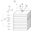
- FIG. 1 is a schematic diagram showing one embodiment of a liquid crystal display device of the present invention.
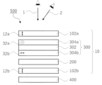
- 1 is a schematic cross-sectional view showing one embodiment of a liquid crystal display device of the present invention.
- 1 is a schematic cross-sectional view showing one embodiment of a liquid crystal display device of the present invention.
- 5A to 5C are schematic cross-sectional views illustrating changes in the polarization state in a liquid crystal display device of the present invention.
- 5A to 5C are schematic cross-sectional views illustrating changes in the polarization state in a liquid crystal display device of the present invention.
- 5A to 5C are schematic cross-sectional views illustrating changes in the polarization state in a liquid crystal display device of the present invention.
- 5A to 5C are schematic cross-sectional views illustrating changes in the polarization state in a liquid crystal display device of the present invention.
- parallel and perpendicular do not mean parallel and perpendicular in the strict sense, but mean a range of ⁇ 5° from parallel or perpendicular.
- polar angle means the angle with the normal direction of the film.
- liquid crystal composition and liquid crystalline compound conceptually include those that no longer exhibit liquid crystallinity due to curing or the like.
- each component may be used alone or in combination of two or more substances corresponding to each component.
- the content of the component refers to the total content of the substances used in combination, unless otherwise specified.
- “(meth)acrylate” is a notation representing "acrylate” or “methacrylate”
- “(meth)acrylic” is a notation representing "acrylic” or “methacrylic”
- “(meth)acryloyl” is a notation representing "acryloyl” or "methacryloyl”.
- NAR-4T Abbe refractometer
- measurements can be made using a multi-wavelength Abbe refractometer DR-M2 (manufactured by Atago Co., Ltd.) in combination with an interference filter. Values in the Polymer Handbook (JOHN WILEY & SONS, INC.) and catalogs of various optical films can also be used.
- Re( ⁇ ) and Rth( ⁇ ) respectively represent an in-plane retardation and a retardation in the thickness direction at a wavelength ⁇ , and are expressed by the following formulas (1) and (2) using refractive indices nx, ny, and nz and a film thickness d ( ⁇ m).
- Formula (1): Re( ⁇ ) (nx-ny) ⁇ d ⁇ 1000(nm)
- Formula (2): Rth ( ⁇ ) ((nx+ny)/2-nz) x d x 1000 (nm)
- the wavelength ⁇ is 550 nm.
- the slow axis direction, Re( ⁇ ), and Rth( ⁇ ) can be measured, for example, by using an AxoScan OPMF-1 (manufactured by Optoscience Corporation).
- ⁇ nd is a phase difference caused by a layer in which a rod-shaped or discotic liquid crystal compound is twisted and aligned around the thickness direction, and is represented by the product of the thickness d of the liquid crystal layer and the birefringence ⁇ n of the liquid crystal.
- the twist angle of the liquid crystal compound from one surface to the other surface of the layer in which the liquid crystal compound is twisted and aligned is also called the twist angle of the liquid crystal compound.
- ⁇ n is the value at a wavelength of 550 nm.
- the laminate of the present invention is a laminate having, in this order, a first optically absorptive anisotropic layer, a first polarizer, a first liquid crystal cell, a second polarizer, a second liquid crystal cell, and a second optically absorptive anisotropic layer.
- the absorption axis of the first polarizer and the absorption axis of the second polarizer are perpendicular to each other.
- the first optically absorptive anisotropic layer and the second optically absorptive anisotropic layer each contain a dichroic material, wherein the angle ⁇ 1 between the central axis of transmittance of the first optically absorptive anisotropic layer and the normal direction to the surface of the first optically absorptive anisotropic layer is 0 to 45°, and the angle ⁇ 2 between the central axis of transmittance of the second optically absorptive anisotropic layer and the normal direction to the surface of the second optically absorptive anisotropic layer is 0 to 45°.
- FIG. 1 is a schematic diagram showing one embodiment of a liquid crystal display device using the laminate of the present invention.
- a liquid crystal display device 500 shown in Fig. 1 includes, in this order from the viewing side, a laminate 10 and a surface light source 400. Note that the viewing side in Fig. 1 is the side on which an arrow indicating a front viewing direction 1 is drawn.
- the laminate 10 includes, in this order, a first optically absorptive anisotropic layer 102a, a liquid crystal panel 300, a second liquid crystal cell 200, and a second optically absorptive anisotropic layer 102b.
- the liquid crystal panel 300 includes, in this order from the viewing side, a first polarizer 304a, a first liquid crystal cell 302, and a second polarizer 304b.
- a front viewing direction 1 is parallel to the z-axis direction
- a first viewing direction 2 is parallel to the zx plane
- a second viewing direction 3 is parallel to the yz plane.
- FIG. 2 is a schematic cross-sectional view of the liquid crystal display device 500 in a plane (parallel to the zx plane) including the front viewing direction 1 and the first viewing direction 2 in FIG. 2, in the liquid crystal display device 500, the absorption axis 32a of the first polarizer and the absorption axis 32b of the second polarizer are perpendicular to each other.
- the absorption axis 32a of the first polarizer is parallel to the depth direction of the paper in FIG. 2, and the absorption axis 32b of the second polarizer is perpendicular to the depth direction of the paper in FIG. 2.
- the angle ⁇ 1 between the transmittance axis 12a of the first optically absorptive anisotropic layer 102a and the normal to the surface of the first optically absorptive anisotropic layer 102a is 0°.
- the angle ⁇ 2 between the transmittance axis 12b of the second optically absorptive anisotropic layer 102b and the normal to the surface of the second optically absorptive anisotropic layer 102b is 0°.
- the alignment direction of the liquid crystal compound in each pixel of the first liquid crystal cell 302 is controlled to adjust the amount of light passing through each pixel of the liquid crystal panel 300, thereby displaying an image.
- the first liquid crystal cell 302 and the second liquid crystal cell 200 are of a twisted nematic type (TN type).
- TN type liquid crystal cell the liquid crystal compound is usually twisted and aligned with the thickness direction of the first liquid crystal cell 302 or the second liquid crystal cell 200 as an axis when no voltage is applied.
- the orientation direction of the liquid crystal compound is usually rotated by 90° from one surface of the liquid crystal cell to the other surface of the liquid crystal cell when no voltage is applied.
- linearly polarized light incident on a TN type liquid crystal cell when no voltage is applied usually rotates by 90° and exits the TN type liquid crystal cell.
- linearly polarized light incident on a TN type liquid crystal cell when a voltage is applied usually exits the TN type liquid crystal cell while maintaining its polarization state. Therefore, in a liquid crystal panel in which a normal TN type liquid crystal cell is arranged between two polarizing plates arranged in a crossed Nicol configuration, when no voltage is applied, light is transmitted and a white display is produced.
- a displayed image can be viewed from a front viewing direction 1, but cannot be viewed in a first viewing direction 2 inclined to the right side of the paper surface from the front viewing direction 1 at an azimuth angle perpendicular to the absorption axis of the first polarizer 304a. That is, light emitted from the liquid crystal display device 500 in the first viewing direction 2 is blocked.
- the above principle will be explained below.
- the change in the polarization state in the first viewing direction 2 shown in Fig. 2 is shown in Fig. 4 and Fig. 5.
- the outline arrows represent the transmitted polarized light components
- the directions shown between the layers represent the polarization directions of the transmitted polarized light components.
- Figure 4 and Fig. 5 are the same as those in Fig. 1 and Fig. 2, and the aspects are the same as those in Fig. 1 and Fig. 2.
- Figure 4 shows the change in polarization state when no voltage is applied to the first liquid crystal cell 302 and the second liquid crystal cell 200
- Figure 5 shows the change in polarization state when no voltage is applied to the first liquid crystal cell 302 and a voltage is applied to the second liquid crystal cell 200.
- the dichroic material absorbs the polarized light component in the direction perpendicular to the depth direction of the paper, and more of the polarized light component in the depth direction of the paper in FIG. 2 is transmitted. 1 that has been transmitted through the second optically absorptive anisotropic layer 102b has its polarization direction rotated by 90° by the second liquid crystal cell 200.
- the polarization component emitted from the second liquid crystal cell 200 has the same direction as the absorption axis 32b of the second polarizer 304b, and the polarization component is absorbed by the second polarizer 304b. Therefore, when no voltage is applied to the first liquid crystal cell 302 and the second liquid crystal cell 200, the light emitted in the first viewing direction 2 is blocked.
- the second optically absorptive anisotropic layer 102b transmits more polarized light components in the direction into the paper of FIG.
- the polarization state of the light passing through the second liquid crystal cell 200 is maintained. Therefore, the polarized component passing through the second liquid crystal cell 200 remains in the depth direction of the paper in Fig.
- the polarized component in the depth direction of the paper in Fig. 2 that enters the first liquid crystal cell 302 rotates its direction by 90°, enters the first polarizer 304a, and passes through the first polarizer 304a.
- the polarization direction of the polarized component that exits the first polarizer 304a is perpendicular to the depth direction of the paper. Then, the polarized light component that has exited the first polarizer 304a is absorbed by the dichroic material of the first optically absorptive anisotropic layer 102a.
- the angle ⁇ 1 between the transmittance central axis 12a of the first optically absorptive anisotropic layer 102a and the normal direction to the surface of the first optically absorptive anisotropic layer 102a is 0°, and the polarized light component in the direction perpendicular to the depth direction of the paper is easily absorbed. Therefore, even when no voltage is applied to the first liquid crystal cell 302 and a voltage is applied to the second liquid crystal cell 200, the light emitted in the first viewing direction 2 is blocked.
- the characteristics in the first viewing direction 2 at a position tilted to the right side of the paper from the front viewing direction 1 at an azimuth angle perpendicular to the absorption axis of the first polarizer 304a have been described.
- a mechanism similar to that when viewed from the first viewing direction 2 occurs, and light is blocked.
- the liquid crystal display device 500 shown in FIG. 2 when the liquid crystal display device 500 is viewed from an oblique direction perpendicular to the absorption axis of the first polarizer 304a, the image displayed on the liquid crystal display device 500 is blocked.
- Fig. 3 is a cross-sectional schematic diagram of a liquid crystal display device 500 in a plane (parallel to the yz plane) including the front viewing direction 1 and the second viewing direction 3 in Fig. 1.
- the liquid crystal display device 500 shown in Fig. 3 is similar to the liquid crystal display devices shown in Figs. 1 and 2, and only the direction shown as a cross section is different, so the symbols of each component shown in Fig. 3 are the same as those in Figs. 1 and 2, and the embodiment is the same as that in Figs. 1 and 2.
- the directions of the absorption axis 32a of the first polarizer 304a and the absorption axis 32b of the second polarizer 304b are rotated by 90° from those shown in Fig. 2. 3, it is possible to switch whether or not a displayed image is viewable from a front viewing direction 1, and whether or not the displayed image is viewable in a second viewing direction 3 inclined to the right side of the paper surface from the front viewing direction 1 at an azimuth angle parallel to the absorption axis of the first polarizer 304a. In other words, it is possible to switch whether or not light emitted from the liquid crystal display device 500 in the second viewing direction 3 is blocked.
- the above principle will be explained below. The change in the polarization state in the second viewing direction 3 shown in Fig.
- FIG. 6 shows the outline arrows represent the polarized light components transmitted in the second viewing direction 3, and the directions shown between the layers represent the polarization directions of the polarized light components transmitted.
- the symbols of the components shown in Figs. 6 and 7 are the same as those in Figs. 1 to 3, and the aspects are the same as those in Figs. 1 to 3.
- Figure 6 shows the change in polarization state when no voltage is applied to the first liquid crystal cell 302 and the second liquid crystal cell 200
- Figure 7 shows the change in polarization state when no voltage is applied to the first liquid crystal cell 302 and a voltage is applied to the second liquid crystal cell 200.
- the polarization component emitted from the second liquid crystal cell 200 is oriented in a direction perpendicular to the absorption axis 32b of the second polarizer 304b, and is transmitted through the second polarizer 304b.
- the polarized light component transmitted through the second polarizer 304b is rotated by 90° by the first liquid crystal cell 302, enters the first polarizer 304a, and is transmitted through the first polarizer 304a.
- the polarization direction of the polarized light component exiting the first polarizer 304a is the depth direction of the paper.
- the polarized component that exits the first polarizer 304a enters the first optically absorptive anisotropic layer 102a, but since the polarization direction of the polarized component is the depth direction of the paper, which is perpendicular to the transmittance central axis 12a, the polarized component is transmitted through the first optically absorptive anisotropic layer 102a without being absorbed by the dichroic material contained in the first optically absorptive anisotropic layer 102a. Therefore, when no voltage is applied to the first liquid crystal cell 302 and the second liquid crystal cell 200, the light emitted in the second viewing direction 3 is transmitted.
- the second optically absorptive anisotropic layer 102b transmits more polarized light components in the direction into the paper of FIG.
- the polarization state of the light passing through the second liquid crystal cell 200 is maintained.
- the polarization direction of the polarized light component output from the second liquid crystal cell 200 is the depth direction of the paper in Fig.
- the characteristics in the second viewing direction 3 at a position tilted to the right on the paper from the front viewing direction 1 at an azimuth angle parallel to the absorption axis of the first polarizer 304a have been described.
- a mechanism similar to that when viewed from the second viewing direction 3 occurs.
- the light emitted in the front viewing direction 1 is emitted without being blocked.
- the reason for this will be explained below.
- the front viewing direction 1 and the transmittance central axis 12b of the second optically absorptive anisotropic layer 102b are parallel to each other. Therefore, the light incident on the second polarizer 304b includes a polarized component in the depth direction of the paper in FIG. 2 and a polarized component in a direction perpendicular to the depth direction of the paper in FIG. 2.
- the polarized component in a direction parallel to the absorption axis 32b of the second polarizer 304b is absorbed, but the polarized component in a direction perpendicular to the absorption axis 32b is transmitted through the second polarizer 304b.
- the polarized component incident on the first liquid crystal cell 302 has its polarization direction rotated by 90° by the first liquid crystal cell 302. Therefore, the light is transmitted through the first polarizer 304a.
- the polarized light component emitted in the front viewing direction 1 is emitted without being absorbed by the first optically absorptive anisotropic layer 102a. Therefore, when no voltage is applied to the first liquid crystal cell 302 and the second liquid crystal cell 200, light emitted in the front viewing direction 1 is transmitted.
- the polarization direction does not change, and the light incident on the second polarizer 304b contains a polarization component in the depth direction of the paper in FIG. 2 and a polarization component in a direction perpendicular to the depth direction of the paper in FIG. 2. Therefore, the light emitted in the front viewing direction 1 is transmitted, just as in the state when no voltage is applied to the second liquid crystal cell 200.
- a liquid crystal display device using the laminate of the present invention As described above, in a liquid crystal display device using the laminate of the present invention, light emitted in the front viewing direction 1 in Figures 1 and 2 is emitted from the liquid crystal display device, and light emitted in the first viewing direction 2 is blocked regardless of whether a voltage is applied to second liquid crystal cell 200. Moreover, light emitted in the second viewing direction 3 in Figures 1 and 3 can be switched between being blocked and being emitted depending on whether a voltage is applied to second liquid crystal cell 200.
- the obtained liquid crystal display device has excellent light-shielding properties. Specifically, light in the second viewing direction 3 in FIG.
- the first optically absorptive anisotropic layer 102a is disposed on the most visible side. In the liquid crystal panel 300, scattering that changes the polarization state may occur, but even if such scattering occurs, the scattered light may be absorbed by the first optically absorptive anisotropic layer 102a, and therefore the resulting liquid crystal display device is believed to have excellent light blocking properties.
- the laminate of the present invention has excellent light resistance.
- the reason for this is not entirely clear, but the present inventors speculate as follows.
- the second optically absorptive anisotropic layer 102b is disposed on the side opposite to the viewing side. Therefore, when external light is irradiated onto the laminate, the external light is likely to be absorbed by other layers before it reaches the second optically absorptive anisotropic layer 102b.
- the second optically absorptive anisotropic layer 102b is less susceptible to deterioration due to external light, and as a result, it is believed that the resulting liquid crystal display device has excellent light resistance.
- FIGS. 1 to 3 is merely one embodiment of the present invention, and the present invention is not limited to the above embodiment.
- the stacking direction of liquid crystal panels 300 in stack 10 by rotating the stacking direction of liquid crystal panels 300 in stack 10 by 90 degrees, it becomes possible to switch between blocking and emitting light in first viewing direction 2 in FIG. 1, and light emitted in second viewing direction 3 is blocked.
- the first liquid crystal cell 302 and the second liquid crystal cell 200 may be liquid crystal cells of different types.
- the angle ⁇ 1 between the transmittance central axis 12a of the first optically absorptive anisotropic layer 102a and the normal direction to the surface of the first optically absorptive anisotropic layer 102a may be 0 to 45°, and the angle ⁇ 1 can be adjusted according to the direction in which an image is to be viewed.
- the angle ⁇ 2 between the transmittance central axis 12b of the second optically absorptive anisotropic layer 102b and the normal direction to the surface of the second optically absorptive anisotropic layer 102b may be 0 to 45°, and the angle ⁇ 2 can be adjusted according to the direction in which an image is to be viewed.
- the first optically absorptive anisotropic layer in the laminate of the present invention contains a dichroic material, and the angle ⁇ 1 between the central axis of transmittance of the first optically absorptive anisotropic layer and the normal direction to the surface of the first optically absorptive anisotropic layer is 0 to 45°.
- the central axis of transmittance and the orientation direction of the dichroic material usually coincide with each other. As described above, the angle ⁇ 1 can be adjusted according to the direction in which the image is to be viewed.
- the angle ⁇ 1 is preferably 0 to 10°.
- the transmittance central axis of the first optically absorptive anisotropic layer may be oriented in a different direction depending on the location in the plane of the first optically absorptive anisotropic layer.
- an in-vehicle display having a curved display surface in order to prevent emitted light from any position from being reflected on the windshield or the like and to enable the driver to properly view the displayed image, it is preferable to adjust the direction of the transmittance central axis of the first optically absorptive anisotropic layer in accordance with the curved surface.
- the transmittance central axis means the direction in which the transmittance is highest when the transmittance is measured by changing the tilt angle (polar angle) and tilt direction (azimuth angle) relative to the normal direction of the surface of the first optically absorptive anisotropic layer.
- the azimuth angle direction in which the transmittance central axis is tilted is detected using AxoScan OPMF-1 (manufactured by Optoscience Co., Ltd.), and the transmittance is derived by measuring the Mueller matrix while changing the polar angle in the direction of the azimuth angle, and the direction (polar angle) in which the transmittance is highest is taken as the direction of the transmittance central axis of the optically absorptive anisotropic layer.
- the direction of this polar angle is the angle formed by the transmittance central axis in the optically absorptive anisotropic layer and the normal direction of the optically absorptive anisotropic layer.
- the transmittance central axis (polar angle) of the first optically absorptive anisotropic layer is measured at 15 arbitrarily selected locations in the first optically absorptive anisotropic layer, and the average of the polar angles is regarded as the transmittance central axis in the first optically absorptive anisotropic layer.
- these optical measurements are carried out using light with a wavelength of 550 nm, unless otherwise specified.
- the light transmittance of the first optically absorptive anisotropic layer in a direction parallel to the central axis of the transmittance is preferably 50% or more, more preferably 70%.
- the upper limit of the transmittance is not particularly limited, but may be, for example, 95% or less, and is often 90% or less.
- the transmittance of the first optically absorptive anisotropic layer in a direction inclined by 30° from the central axis of the transmittance is preferably 30% or less, more preferably 15% or less.
- the lower limit of the transmittance is not particularly limited, but may be, for example, 0.5% or more, and is often 5% or more.
- the first optically absorptive anisotropic layer in the present invention has a layer containing at least one dichroic material (e.g., a dichroic dye).
- a dichroic material e.g., a dichroic dye
- the dichroic dye will be described as an example of the dichroic material.
- the dichroic substance contained in the first light absorptive anisotropic layer of the present invention is not particularly limited as long as it is a substance that exhibits dichroism, and examples of the dichroic substance include dichroic dyes, dichroic azo dye compounds, ultraviolet absorbing substances, infrared absorbing substances, nonlinear optical substances, carbon nanotubes, anisotropic metal nanoparticles, and inorganic substances.
- the first light absorption anisotropic layer may contain two or more dichroic substances.
- the first light absorption anisotropic layer contains a cyan dye exhibiting dichroism in the red wavelength region, a magenta dye exhibiting dichroism in the green wavelength region, and a yellow dye exhibiting dichroism in the blue wavelength region.
- the color can be made neutral and the viewing angle control effect can be exerted over the entire wavelength region of visible light.
- a dichroic substance is a substance that exhibits dichroism, and dichroism refers to a property in which the absorbance differs depending on the direction of polarization.
- the degree of orientation of the dichroic material at a wavelength of 550 nm is preferably 0.95 or more.
- the transmittance in the direction of the absorption axis i.e., the direction in which light is to be transmitted
- the degree of orientation of the dichroic material at a wavelength of 420 nm is preferably 0.93 or more.
- the thickness of the first optically absorptive anisotropic layer is not particularly limited, but from the viewpoint of flexibility, it is preferably from 100 to 8000 nm, and more preferably from 300 to 5000 nm.
- the dichroic substance a dichroic dye is preferable, and a dichroic azo dye compound is more preferable.
- the dichroic azo dye compound means an azo dye compound whose absorbance varies depending on the direction.
- the dichroic azo dye compound may or may not exhibit liquid crystallinity.
- the dichroic azo dye compound exhibits liquid crystallinity, it may exhibit either a nematic liquid crystal phase or a smectic liquid crystal phase.
- the temperature range in which the liquid crystal phase is exhibited is preferably from room temperature (about 20 to 28° C.) to 300° C., and more preferably from 50 to 200° C. from the viewpoints of handling and manufacturing suitability.
- the composition for forming the optically absorptive anisotropic layer used in forming the first optically absorptive anisotropic layer described below contains a dichroic azo dye compound having a crosslinkable group.
- the crosslinkable group include a (meth)acryloyl group, an epoxy group, an oxetanyl group, and a styryl group, and among these, a (meth)acryloyl group is preferable.
- Examples of the dichroic azo dye compound preferably used in the present invention include a first dichroic azo dye compound, a second dichroic azo dye compound, and a third dichroic azo dye compound.
- the first dichroic azo dye compound is a dichroic azo dye compound having a maximum absorption wavelength in the wavelength range of 560 nm to 700 nm
- the second dichroic azo dye compound is a dichroic azo dye compound having a maximum absorption wavelength in the wavelength range of 455 nm to less than 560 nm
- the third dichroic azo dye compound is a dichroic azo dye compound having a maximum absorption wavelength in the wavelength range of 380 nm to 455 nm.
- first dichroic azo dye compound examples include, for example, the compounds described in paragraphs [0161] to [0171] of WO 2022/138548, the compounds described in paragraphs [0172] to [0180] of WO 2022/138548, and the compounds described in paragraphs [0183] to [0206] of WO 2022/138548.
- the content of the dichroic material is preferably 1 to 30% by mass, more preferably 5 to 25% by mass, and even more preferably 10 to 20% by mass, based on the total solid mass of the first light-absorption anisotropic layer.
- the dichroic material contained in the optically absorptive anisotropic layer preferably forms an ordered structure, because this increases the degree of orientation.
- the ordered structure means a state in which the dichroic material gathers to form an aggregate in the light absorption anisotropic layer, and the molecules of the dichroic material are periodically arranged in the aggregate.
- the array structure may be formed only of a dichroic material, or may be formed of a liquid crystal compound and a dichroic material, which will be described later.
- the array structure may be formed of one kind of dichroic material, or may be formed of multiple kinds of dichroic materials.
- the optically absorptive anisotropic layer may have a mixture of an arrangement structure formed from one type of dichroic material and an arrangement structure formed from another type of dichroic material. Furthermore, when the optically absorptive anisotropic layer contains multiple types of dichroic substances, all of the multiple types of dichroic substances contained in the optically absorptive anisotropic layer may form an array structure, or only some of the types of dichroic substances may form an array structure.
- the degree of orientation of the first optically absorptive anisotropic layer is higher, when the cross section of the first optically absorptive anisotropic layer is observed with a scanning transmission electron microscope, it is preferable that 3 or more arrangement structures satisfying L ⁇ 240 nm are observed per 40 ⁇ m2, more preferably 3 to 15 arrangement structures are observed, and even more preferably 3 to 10 arrangement structures are observed, where L is the length of the major axis of the arrangement structure and D is the length of the minor axis of the arrangement structure.
- STEM scanning transmission electron microscope
- the first optically absorptive anisotropic layer is cut using an ultramicrotome to prepare an ultrathin slice having a thickness of 100 nm in the film thickness direction.
- the ultrathin section is then placed on a grid with a carbon support film for STEM observation. Thereafter, the grid is placed in a scanning transmission electron microscope, and the cross section is observed at an electron beam acceleration voltage of 30 kV.
- the length L of the major axis and the length D of the minor axis of the array structure are measured as follows. First, as described above, a cross section of the first optically absorptive anisotropic layer is observed by STEM, the captured image is analyzed, a frequency histogram is created, and the maximum frequency and the standard deviation of the frequency distribution are determined. Next, the frequency that is 1.3 times the standard deviation on the darker side from the maximum frequency is set as the threshold value. Next, an image is created in which the brightness is binarized using this threshold value, and from among the binarized dark regions, portions with a major axis of 30 nm or more are extracted as array structures.
- each extracted sequence structure is approximated as an ellipse, and the length of the major axis of the approximated ellipse is set to the length L of the major axis of the sequence structure, and the length of the minor axis of the approximated ellipse is set to the length D of the minor axis of the sequence structure.
- the length L of the long axis and the length D of the short axis of such an array structure may be measured using known image processing software, such as the image processing software "ImageJ.”
- the first optically absorptive anisotropic layer is preferably formed using a liquid crystal composition containing a dichroic material and a liquid crystal compound, and therefore preferably contains a component derived from the liquid crystal compound.
- a liquid crystal composition containing a dichroic material and a liquid crystal compound, and therefore preferably contains a component derived from the liquid crystal compound.
- low molecular weight liquid crystal compound refers to a liquid crystal compound that does not have a repeating unit in its chemical structure.
- polymeric liquid crystal compound refers to a liquid crystal compound that has a repeating unit in its chemical structure.
- the low molecular weight liquid crystal compound may be either a compound exhibiting a nematic liquid crystal phase or a compound exhibiting a smectic liquid crystal phase, but from the viewpoint of increasing the degree of orientation, a compound exhibiting a smectic liquid crystal phase is preferred.
- a compound exhibiting a smectic liquid crystal phase is preferred.
- the liquid crystal compounds described in JP 2013-228706 A can be mentioned.
- polymeric liquid crystal compound examples include the thermotropic liquid crystal polymers described in JP 2011-237513 A. From the viewpoint of excellent strength (particularly the bending resistance of the film), the polymeric liquid crystal compound preferably has a repeating unit having a crosslinkable group at the end.
- the crosslinkable group examples include the polymerizable groups described in paragraphs [0040] to [0050] of JP 2010-244038 A. Among these, from the viewpoint of improving reactivity and suitability for synthesis, acryloyl groups, methacryloyl groups, epoxy groups, oxetanyl groups, and styryl groups are preferred, and acryloyl groups and methacryloyl groups are more preferred.
- the polymeric liquid crystal compound When the first light absorbing anisotropic layer contains a polymeric liquid crystal compound, the polymeric liquid crystal compound preferably forms a nematic liquid crystal phase.
- the temperature range in which the nematic liquid crystal phase is exhibited is preferably room temperature (23°C) to 450°C, and from the viewpoint of handling and manufacturing suitability, preferably 50 to 400°C.
- the content of the component derived from the liquid crystal compound in the first light absorptive anisotropic layer is preferably 25 to 2000 parts by mass, more preferably 100 to 1300 parts by mass, and even more preferably 200 to 900 parts by mass, relative to 100 parts by mass of the dichroic substance.
- the liquid crystal compound may be contained alone or in combination with two or more kinds.
- the content of the components derived from the liquid crystal compounds means the total content of the liquid crystal compounds.
- the liquid crystal composition used for forming the first light absorptive anisotropic layer may further contain additives such as a solvent, a vertical alignment agent, an interface improver, a leveling agent, a polymerizable component, a polymerization initiator (e.g., a radical polymerization initiator), a durability improver, etc.
- additives such as a solvent, a vertical alignment agent, an interface improver, a leveling agent, a polymerizable component, a polymerization initiator (e.g., a radical polymerization initiator), a durability improver, etc.
- a polymerization initiator e.g., a radical polymerization initiator
- the laminate of the present invention may include other layers different from the first optically absorptive anisotropic layer and the layers described below.
- the other layers are layers that are in direct contact with the first optically absorptive anisotropic layer, or indirectly in contact with the first optically absorptive anisotropic layer via a layer different from the first optically absorptive anisotropic layer and the layers described below.
- the other layers that are in direct or indirect contact with the first optically absorptive anisotropic layer are described below.
- the laminate of the present invention may include a substrate layer as another layer.
- the substrate layer is not particularly limited, but a transparent film or sheet is preferable, and a known transparent resin film, transparent resin plate, transparent resin sheet, glass, etc. can be used.
- a cellulose acylate film e.g., a cellulose triacetate film, a cellulose diacetate film, a cellulose acetate butyrate film, a cellulose acetate propionate film
- a polyethylene terephthalate film e.g., a polyethersulfone film
- a polyacrylic resin film e.g., a polyurethane resin film
- a polyester film a polycarbonate film
- a polysulfone film a polyether film, a polymethylpentene film, a polyether ketone film, a (meth)acrylonitrile film, etc.
- a cellulose acylate film e.g., a cellulose triacetate film, a cellulose diacetate film, a cellulose acetate butyrate film, a cellulose acetate propionate film
- a polyethylene terephthalate film e.g., a polyethersulfone film, a polyacryl
- cellulose acylate films are preferred, and cellulose triacetate films are particularly preferred, because they have high transparency, little optical birefringence, are easy to produce, and are generally used as protective films for polarizing plates.
- the thickness of the transparent resin film is preferably 20 ⁇ m to 100 ⁇ m.
- the laminate of the present invention may have an alignment layer between the substrate layer and the first optically absorptive anisotropic layer as another layer.
- the alignment film may be any layer as long as it can cause the dichroic material (liquid crystal compound) on the alignment film to be aligned in a desired state.
- a film formed from a polyfunctional acrylate compound and polyvinyl alcohol may be used, with polyvinyl alcohol being particularly preferred.
- the alignment film may be a photo-alignment film.
- the dichroic material By irradiating a photo-alignment film containing an azo compound or a cinnamoyl compound with UV light from an oblique direction, the dichroic material can be aligned at an angle with respect to the normal direction of the film.
- the laminate of the present invention may further include a barrier layer as another layer.
- the barrier layer is also called a gas barrier layer (oxygen barrier layer), and has the function of protecting the first optically absorptive anisotropic layer from gases such as oxygen in the atmosphere, moisture, or compounds contained in adjacent layers.
- the first optically absorptive anisotropic layer may have a problem of internal reflection due to the high refractive index of the first optically absorptive anisotropic layer.
- a refractive index adjustment layer may be used.
- the refractive index adjustment layer is preferably disposed in contact with the first optically absorptive anisotropic layer and is a layer for performing so-called index matching.
- the in-plane average refractive index of the refractive index adjustment layer at a wavelength of 550 nm is preferably 1.55 or more and 1.70 or less.
- the method for forming the first optically absorptive anisotropic layer is not particularly limited, and examples thereof include a method including, in this order, a step of applying a composition for forming an optically absorptive anisotropic layer to form a coating film (hereinafter also referred to as a "coating film forming step") and a step of orienting a liquid crystalline component or a dichroic material contained in the coating film (hereinafter also referred to as an "orientation step").
- the liquid crystal component is a component including not only the above-mentioned liquid crystal compound but also a dichroic substance having liquid crystallinity when the above-mentioned dichroic substance has liquid crystallinity.
- the coating film forming step is a step of forming a coating film by applying a composition for forming an optically absorptive anisotropic layer.
- a composition for forming an optically absorptive anisotropic layer that contains a solvent or by using a composition for forming an optically absorptive anisotropic layer that has been made into a liquid such as a molten liquid by heating or the like, it becomes easy to apply the composition for forming an optically absorptive anisotropic layer.
- compositions for forming an optically absorptive anisotropic layer include known methods such as roll coating, gravure printing, spin coating, wire bar coating, extrusion coating, direct gravure coating, reverse gravure coating, die coating, spraying, and inkjet methods.
- the alignment step is a step of aligning the liquid crystal component contained in the coating film, thereby obtaining a first optically absorptive anisotropic layer.
- the orientation step may include a drying treatment. By the drying treatment, components such as a solvent can be removed from the coating film. The drying treatment may be performed by leaving the coating film at room temperature for a predetermined time (for example, natural drying), or may be performed by heating and/or blowing air.
- the liquid crystal component contained in the composition for forming an optically absorptive anisotropic layer may be aligned by the above-mentioned coating film forming step or drying treatment.
- the coating film is dried to remove the solvent from the coating film, thereby obtaining a coating film having optical absorption anisotropy (i.e., the first optically absorptive anisotropic layer).
- the drying treatment is carried out at a temperature equal to or higher than the temperature at which the liquid crystal component contained in the coating film transitions from the liquid crystal phase to the isotropic phase, the heating treatment described below does not need to be carried out.
- the transition temperature from the liquid crystal phase to the isotropic phase of the liquid crystal component contained in the coating film is preferably 10 to 250°C, more preferably 25 to 190°C, from the standpoint of manufacturability, etc.
- a transition temperature of 10°C or higher is preferable because no cooling process or the like is required to lower the temperature to the temperature range in which the liquid crystal phase is exhibited.
- a transition temperature of 250°C or lower is preferable because high temperatures are not required even when heating until the isotropic phase is achieved in order to suppress alignment defects, and this reduces waste of thermal energy as well as deformation and deterioration of the substrate.
- the alignment step preferably includes a heat treatment, which allows the liquid crystal component contained in the coating film to be aligned, so that the coating film after the heat treatment can be suitably used as a light absorption anisotropic layer.
- the heat treatment is preferably performed at 10 to 250° C., more preferably at 25 to 190° C.
- the heating time is preferably 1 to 300 seconds, more preferably 1 to 60 seconds.
- the orientation process may include a cooling process carried out after the heating process.
- the cooling process is a process in which the coated film after heating is cooled to about room temperature (20 to 25°C). This makes it possible to fix the orientation of the liquid crystal component contained in the coated film.
- the method for forming the first optically absorptive anisotropic layer may include a step of curing the first optically absorptive anisotropic layer (hereinafter also referred to as a "curing step") after the above-mentioned alignment step.
- the curing step is carried out by heating and/or light irradiation (exposure) when the compound contained in the first light absorption anisotropic layer has a crosslinkable group (polymerizable group), for example.
- the curing step is preferably carried out by light irradiation from the viewpoint of productivity.
- the light source used for curing may be various light sources such as infrared light, visible light, or ultraviolet light, but ultraviolet light is preferred.
- ultraviolet light may be irradiated while heating during curing, or ultraviolet light may be irradiated through a filter that transmits only specific wavelengths.
- the heating temperature during exposure is preferably 25 to 140° C., although it depends on the transition temperature of the liquid crystal component contained in the liquid crystal film.
- the exposure may be carried out under a nitrogen atmosphere.
- the curing of the liquid crystal film proceeds by radical polymerization, it is preferable to carry out the exposure under a nitrogen atmosphere, since this reduces the inhibition of polymerization caused by oxygen.
- the first optically absorptive anisotropic layer may contain a dichroic dye and a guest-host liquid crystal material, as described in JP-A-2013-541727, for example, and may be capable of electrically driving the orientation direction of the dichroic dye. In this case, it is possible to electrically switch the orientation direction of the dichroic dye.
- the first polarizer contained in the laminate of the present invention is not particularly limited, and a known polarizer (linear polarizer) can be used.
- the absorption axis of the first polarizer and the absorption axis of a second polarizer, which will be described later, are perpendicular to each other.
- linear polarizers include polarizers in which a dichroic material is dyed onto polyvinyl alcohol or other polymer resins and then stretched to align them horizontally, and polarizers in which a dichroic material is oriented horizontally by utilizing the orientation properties of liquid crystals.
- the first polarizer may be a reflective polarizer or a laminate of an absorbing polarizer and a reflective polarizer.
- a reflective polarizer is a polarizer that reflects one polarized light and transmits the other polarized light.
- a reflective polarizer has a reflection axis and a transmission axis in the plane, but the reflection axis works in the same way as the absorption axis in a normal polarizer (absorbent polarizer) in the sense that it does not transmit polarized light in that direction. Therefore, in this specification, the reflection axis of a reflective polarizer can be interpreted as the absorption axis.
- the first liquid crystal cell contained in the laminate of the present invention is disposed between the first polarizer and the second polarizer, and adjusts the amount of light passing through the liquid crystal panel consisting of the first polarizer, the first liquid crystal cell, and the second polarizer.
- the first liquid crystal cell is not particularly limited as long as it can adjust the amount of light transmitted through the liquid crystal panel, and a known liquid crystal cell can be used.
- the first liquid crystal cell usually has a plurality of regions in which the alignment direction of the liquid crystal compound can be controlled, and each of the regions independently controls the alignment direction of the liquid crystal compound in each region, thereby adjusting the amount of light transmitted through the region of the liquid crystal panel corresponding to each region.
- the type of the first liquid crystal cell is not particularly limited, and any known type may be used.
- Examples of the type of the first liquid crystal cell include an in-plane switching (IPS) type liquid crystal cell, a vertical alignment (VA) type liquid crystal cell, and an optically compensated bend (OCB) type liquid crystal cell, in addition to the TN type liquid crystal cell described above.
- the first liquid crystal cell may be a STN (Super Twisted Nematic) type liquid crystal cell having a twist angle of 180° or more, or a VATN (Vertically Aligned Twisted Nematic) type liquid crystal cell disclosed in Japanese Patent Application Laid-Open No.
- the first liquid crystal cell is preferably selected from the group consisting of a TN type liquid crystal cell, an IPS type liquid crystal cell, and a VA type liquid crystal cell.
- TN type liquid crystal cells when no voltage is applied, the rod-shaped liquid crystal molecules are essentially aligned horizontally, and are further twisted at an angle of 60 to 120 degrees along the thickness direction.
- TN type liquid crystal cells are most commonly used as color TFT (Thin Film Transistor) liquid crystal display devices, and are described in numerous publications.
- VA-type liquid crystal cells the rod-shaped liquid crystal molecules are aligned substantially vertically when no voltage is applied.
- VA-type liquid crystal cells include (1) narrowly defined VA-type liquid crystal cells (described in Japanese Patent Laid-Open Publication No. 2-176625) in which the rod-shaped liquid crystal molecules are aligned substantially vertically when no voltage is applied and substantially horizontally when voltage is applied, as well as (2) multi-domain (MVA-type) liquid crystal cells (described in SID97, Digestof tech.
- an IPS type liquid crystal cell In an IPS type liquid crystal cell, rod-shaped liquid crystal molecules are aligned substantially parallel to the substrate, and the liquid crystal molecules respond in a planar manner when a voltage is applied between the electrodes to generate an electric field parallel to the substrate surface.
- An IPS type liquid crystal cell displays black when no voltage is applied, and the absorption axes of the pair of upper and lower polarizing plates are perpendicular to each other.
- the second polarizer contained in the laminate of the present invention is not particularly limited, and a known polarizer (linear polarizer) can be used.
- the absorption axis of the first polarizer and the absorption axis of the second polarizer are perpendicular to each other. Examples and preferred aspects of the second polarizer are similar to those of the first polarizer, and therefore description thereof will be omitted.
- the second liquid crystal cell contained in the laminate of the present invention is disposed between the second polarizer and the second optically absorptive anisotropic layer, and controls the polarization state of polarized light passing through the second liquid crystal cell.
- the second liquid crystal cell is not particularly limited as long as it can control the polarization state of polarized light passing through the second liquid crystal cell, and any known liquid crystal cell can be used.
- the second liquid crystal cell may have a plurality of regions capable of controlling the alignment direction of the liquid crystal compound, and in this case, the alignment direction of the liquid crystal compound in each region can be controlled independently, and the polarization state of the polarized light transmitted through each region can be adjusted.
- the second liquid crystal cell has a plurality of regions capable of controlling the alignment direction of the liquid crystal compound, it is also possible to control the alignment direction of the liquid crystal compound in only a specific region, and therefore it is possible to switch between blocking and emitting light emitted from a region of the liquid crystal display device corresponding to the specific region.
- the region in which the alignment direction of the liquid crystal compound can be controlled does not have a plurality of regions as described above, but may be a single region.
- the type of the second liquid crystal cell is not particularly limited, and any known type can be used.
- the type of the second liquid crystal cell in addition to the TN type liquid crystal cell described above, the types mentioned for the first liquid crystal cell can be used.
- the second liquid crystal cell is preferably selected from the group consisting of a TN type liquid crystal cell, an IPS type liquid crystal cell, and a VA type liquid crystal cell.
- the second liquid crystal cell is a liquid crystal cell in which the in-plane retardation of the second liquid crystal cell can be switched between 0 and ⁇ /2
- An example of a liquid crystal cell capable of switching the in-plane retardation between 0 and ⁇ /2 is a VA type liquid crystal cell.
- the in-plane retardation of ⁇ /2 does not strictly require that the in-plane retardation be ⁇ /2, and the in-plane retardation at a wavelength of 550 nm is preferably 235 to 315 nm, and more preferably 255 to 295 nm.
- the second liquid crystal cell 200 is changed from a TN type liquid crystal cell to a VA type liquid crystal cell capable of switching the in-plane retardation between 0 and ⁇ /2.
- the light emitted in the second viewing direction 3 in FIG. 3 can be switched between being blocked and being emitted depending on whether or not a voltage is applied to the second liquid crystal cell.
- the liquid crystal compound is aligned in the thickness direction of the liquid crystal cell when no voltage is applied, whereas when a voltage is applied to the liquid crystal cell, the liquid crystal compound is aligned in the in-plane direction of the liquid crystal cell, generating an in-plane retardation.
- the linearly polarized light components in the first viewing direction 2 and the second viewing direction 3 in Fig. 2 and Fig. 3 are converted into polarized light in a direction perpendicular to the first viewing direction 2 and the second viewing direction 3 in Fig. 2 and Fig. 3, as in the state in which a voltage is applied to the second liquid crystal cell 200 in the embodiment shown in Fig. 2 and Fig. 3.
- the in-plane retardation of the second liquid crystal cell in the modified example is 0, the polarization state of the polarized light component transmitting through the liquid crystal cell is maintained, as in the state in which no voltage is applied to the second liquid crystal cell 200 in the embodiment shown in Fig. 2 and Fig. 3. Therefore, even when a VA type liquid crystal cell is used for the second liquid crystal cell, similar to the aspects shown in Figures 2 and 3 described above, the light emitted in the second viewing direction 3 in Figure 3 can be switched between being blocked and being emitted depending on whether or not a voltage is applied to the second liquid crystal cell.
- the second liquid crystal cell may be a liquid crystal cell in which the in-plane retardation of the second liquid crystal cell is ⁇ /2 and the direction of the in-plane slow axis can be changed in the in-plane direction.
- An example of such a liquid crystal cell is an IPS type liquid crystal cell.
- the second liquid crystal cell 200 is changed from a TN type liquid crystal cell to an IPS type liquid crystal cell having an in-plane retardation of ⁇ /2 and capable of changing the direction of the in-plane slow axis in the in-plane direction.
- the in-plane retardation of ⁇ /2 does not strictly require that the in-plane retardation be ⁇ /2
- the in-plane retardation at a wavelength of 550 nm is preferably 235 to 315 nm, more preferably 255 to 295 nm. Even in such a modified example, the light emitted in the second viewing direction 3 in FIG.
- the alignment direction of a liquid crystal compound is controlled by the presence or absence of application of a voltage and the level of the voltage.
- the alignment direction of a liquid crystal compound is controlled, the direction of the in-plane slow axis in the liquid crystal cell changes.
- the linearly polarized components in the first viewing direction 2 and the second viewing direction 3 in Fig. 2 and Fig. 3 are converted into polarized light in a direction perpendicular thereto, similar to the state in which a voltage is applied to the second liquid crystal cell 200 in the embodiment shown in Fig. 2 and Fig. 3.
- the angle between the in-plane slow axis of the second liquid crystal cell in the modified example and the absorption axis of the second polarizer is in the range of 0 ⁇ 10°
- the polarization conversion of the linearly polarized components in the first viewing direction 2 and the second viewing direction 3 in Fig. 2 and Fig. 3 is not substantially performed, and the polarized state is maintained. Therefore, even when an IPS-type liquid crystal cell is used for the second liquid crystal cell, similar to the aspects shown in Figures 2 and 3 described above, the light emitted in the second viewing direction 3 in Figure 3 can be switched between being blocked and being emitted depending on whether or not a voltage is applied to the second liquid crystal cell.
- the second optically absorptive anisotropic layer in the laminate of the present invention contains a dichroic material, and the angle ⁇ 2 between the central axis of transmittance of the second optically absorptive anisotropic layer and the normal direction to the surface of the second optically absorptive anisotropic layer is 0 to 45°.
- the central axis of transmittance and the orientation direction of the dichroic material usually coincide with each other. As described above, the angle ⁇ 2 can be adjusted according to the direction in which the image is desired to be viewed.
- the angle ⁇ 2 is preferably 0 to 10°.
- the central axis of transmittance of the optically absorptive anisotropic layer may be oriented in a different direction depending on the location in the plane of the first optically absorptive anisotropic layer.
- the direction of the central axis of transmittance of the second optically absorptive anisotropic layer in accordance with the curved surface is preferable to adjust the direction of the central axis of transmittance of the second optically absorptive anisotropic layer in accordance with the curved surface.
- the method for measuring the angle ⁇ 2 is the same as the method for measuring the angle ⁇ 1 described above.
- Examples and preferred embodiments of the dichroic dye and liquid crystal compound contained in the second optically absorptive anisotropic layer are similar to those of the first optically absorptive anisotropic layer, and therefore description thereof will be omitted.
- the second optically absorptive anisotropic layer may include layers other than the layer containing the dichroic material, and since these layers are similar to the layers that the first optically absorptive anisotropic layer may include, description thereof will be omitted.
- the laminate of the present invention may include layers (other layers) other than those configured as described above.
- the other layers include an optical compensation film, a protective film, an adhesive layer, an adhesion layer, a diffusion sheet, a prism sheet, and a reflection sheet, etc.
- known layers can be used as the other layers.
- the laminate of the present invention preferably includes an optical compensation film.
- the optical compensation film include a retardation layer, and more specifically, an A plate, a B plate, and a C plate.
- the optical compensation film can be appropriately selected depending on the characteristics of the first optically absorptive anisotropic layer, the second optically absorptive anisotropic layer, the first liquid crystal cell, and the second liquid crystal cell.
- a plates There are two types of A plates: positive A plates (positive A plates, +A plates) and negative A plates (negative A plates, -A plates).
- the refractive index in the slow axis direction in the film plane is nx
- the refractive index in the direction perpendicular to the slow axis in the plane is ny
- the refractive index in the thickness direction is nz
- the positive A plate satisfies the relationship of formula (A1)
- the negative A plate satisfies the relationship of formula (A2).
- the positive A plate has a positive Rth value
- the negative A plate has a negative Rth value.
- the slow axis direction in the film plane is the direction in which the refractive index in the plane is maximum.
- Formula (A1) nx>ny ⁇ nz
- Formula (A2) ny ⁇ nx ⁇ nz
- ⁇ includes not only the case where the two are completely identical, but also the case where the two are substantially identical.
- “substantially the same” includes the case where (ny-nz) ⁇ d is -10 to 10 nm, preferably -5 to 5 nm, in "ny ⁇ nz”, and the case where (nx-nz) ⁇ d is -10 to 10 nm, preferably -5 to 5 nm, in "nx ⁇ nz”.
- d is the thickness of the film.
- the B plate has different values of nx, ny, and nz, and there are two types of B plates: a B plate having a negative Rth that satisfies the relationship of formula (B1), and a B plate having a positive Rth that satisfies the relationship of formula (B2).
- the Nz coefficient of the B plate is preferably 1.5 or more, more preferably 2.0 to 10.0, and even more preferably 3.0 to 5.0.
- C plates There are two types of C plates: a positive C plate (positive C plate, +C plate) and a negative C plate (negative C plate, -C plate).
- a positive C plate satisfies the relationship of formula (C1)
- a negative C plate satisfies the relationship of formula (C2).
- a positive C plate has a negative Rth value
- a negative C plate has a positive Rth value.
- Formula (C1) nz>nx ⁇ ny
- Formula (C2) nz ⁇ nx ⁇ ny
- ⁇ includes not only the case where the two are completely identical, but also the case where the two are substantially identical.
- (nx-ny)xd is 0 to 10 nm, preferably 0 to 5 nm, is also included in "nx ⁇ ny".
- d is the thickness of the film.
- the optical compensation film it is preferable to use a B plate.
- the B plate is disposed between the first light absorbing anisotropic layer and the first polarizer, and it is more preferable that the angle between the absorption axis of the first polarizer and the in-plane slow axis of the B plate is 0 ⁇ 10°.
- the liquid crystal display device of the present invention includes the laminate of the present invention.
- the liquid crystal display device is not particularly limited, and may be, for example, a liquid crystal display device, which may be used as, for example, a liquid crystal display, a head-up display, or a head-mounted display.
- the liquid crystal display device of the present invention may be combined with a configuration that is generally used in this field, for example, the liquid crystal display device of the present invention may be combined with a protective film, an optical compensation film, and the like.
- the liquid crystal display device of the present invention has a laminate 10 and a surface light source 400.
- a backlight that is usually used in liquid crystal display devices can be applied as the surface light source 400.
- a light source for the backlight for example, a cold cathode lamp, a light emitting diode (LED), or the like can be used.
- external light can be used as the surface light source 400.
- the liquid crystal display device of the present invention can be applied to a display capable of narrowing the viewing angle in a specific direction while adjusting the viewing angle in a direction perpendicular to the specific direction, i.e., the liquid crystal display device of the present invention can be applied to a viewing angle control system.
- the in-vehicle display of the present invention includes the above-mentioned liquid crystal display device of the present invention.
- the liquid crystal display device of the present invention When the liquid crystal display device of the present invention is applied to an in-vehicle display, the light emitted in the front viewing direction 1 in FIG. 1 can be emitted from the liquid crystal display device and viewed by, for example, a passenger other than the driver.
- the light emitted in the first viewing direction 2 is always blocked, so that an image displayed on the windshield or the like is not reflected.
- the light emitted in the second viewing direction 3 in FIG. 2 can be switched between being blocked and being emitted, so that the viewing angle in the left and right directions of the in-vehicle display can be controlled.
- the in-vehicle display of the present invention can, for example, be switched to whether or not the displayed image can be viewed in a direction other than the passenger's direction (for example, the driver's direction). It is also preferable that the above switching is controlled according to the driving state of the vehicle.
- Example 1 A laminate was obtained in the following manner, and the liquid crystal display device used in Example 1 was fabricated. [Preparation of Optical Film 1] An optical film having a light absorbing anisotropic layer was prepared by the following procedure.
- the following composition for forming an alignment film 1 was applied to the surface of a commercially available cellulose acylate film (manufactured by Fujifilm Corporation, product name Fujitac TG60UL) with a wire bar.
- the support on which the coating film was formed was dried with hot air at 140° C. for 120 seconds to form an alignment film AL1, thereby obtaining an alignment film-attached cellulose acylate film 1.
- the thickness of the alignment film AL1 was 1 ⁇ m.
- composition for forming alignment film 1 Polymer PA-1 (listed below) 100.00 parts by weight Acid generator PAG-1 (listed below) 8.25 parts by weight Stabilizer DIPEA (listed below) 0.6 parts by weight Butyl acetate 1001.42 parts by weight Methyl ethyl ketone 250.36 parts by weight Club------------------------------------------------------------------------------------------------------------------------------------------------------------------------------------------------------------------------------------------------------------------------------------------------------------------------------------------------------------------------------------------------------------------------------------------------------------------------------------------------------------------------------------------
- Polymer PA-1 (wherein the numerical value for each repeating unit represents the content (mass%) of each repeating unit relative to the total repeating units.)
- composition P1 ⁇ ⁇ The following dichroic substance D-1 0.69 parts by mass ⁇ The following dichroic substance D-2 0.17 parts by mass ⁇ The following dichroic substance D-3 1.13 parts by mass ⁇ The following polymeric liquid crystal compound P -1 8.67 parts by mass - Liquid crystalline compound L-1 below 1.97 parts by mass - IRGACURE OXE-02 (manufactured by BASF) 0.20 parts by mass ⁇ Aligning agent E-1 below 0.16 parts by mass ⁇ Aligning agent E-2 below 0.16 parts by mass ⁇ Surfactant F-2 below 0.007 parts by mass ⁇ Cyclopentanone 78.17 parts by mass parts/benzyl alcohol 8.69 parts by mass ⁇
- Liquid crystal compound L-1 [a mixture of the following liquid crystal compounds (RA), (RB) and (RC) in a mass ratio of 84:14:2]
- the angle of the transmittance central axis calculated above can be interpreted as the value of the optically absorptive anisotropic layer V1.
- the transmittance of the optical film 1 at a wavelength of 550 nm was measured using AxoScan OPMF-1 (manufactured by OptoScience Corporation). The transmittance in the normal direction of the optical film 1 was 78%, and the transmittance in the direction tilted by 30° from the normal direction of the optical film 1 was 17%.
- composition B1 ⁇ 3.80 parts by mass of the above-mentioned modified polyvinyl alcohol PVA-1; 0.20 parts by mass of IRGACURE 2959; 0.08 parts by mass of the following dye compound G-1; 70 parts by mass of water; 30 parts by mass of methanol. ---------------------------------------------------------------------------------------------------------------------------------------------------------------------------------------------------------------------------------------------------------------------------------------------------------------------------------------------------------------------------------------------------------------------------------------------------------------------------------------------------------------------------------------------------------------------
- a horizontal alignment type polyimide alignment film was applied to two glass substrates with ITO electrodes, and the alignment film was formed by high-temperature drying, followed by rubbing treatment. Then, a thermosetting sealant was applied to one of the two glass substrates, and bead spacers (5 ⁇ m in diameter) were applied to the other, and the two glass substrates were bonded together. The two glass substrates were bonded together so that the surfaces on which the alignment films were formed faced each other and the rubbing directions of the alignment films were perpendicular to each other. After bonding, the two glass substrates were vacuum-packed and heat-treated to form an empty liquid crystal cell.
- the rubbed alignment film comes into contact with the injected liquid crystal, so that when no voltage is applied between the ITO electrodes, the liquid crystal layer is twisted and aligned at a twist angle of 90° between the upper and lower glass substrates.
- the liquid crystal is aligned vertically.
- the liquid crystal display device 1 was produced using this liquid crystal panel, optical film 1, a TN type liquid crystal cell, and a backlight with a Lambertian light distribution, so as to have the configuration shown in Table 1.
- Each member was bonded using adhesive SK2057.
- the liquid crystal display device 1 used in Example 1 was produced by bonding, in order from the viewing side, an optical film 1, a liquid crystal panel, a TN type liquid crystal cell, the optical film 1, and a backlight.
- the laminate obtained by bonding the optical film 1, the liquid crystal panel, the TN type liquid crystal cell, and the optical film 1 corresponds to the laminate of the present invention.
- the optical film 1 was bonded such that the cellulose acylate film was on the viewing side.
- a liquid crystal cell (IPS type) is disposed between two polarizers, and the absorption axes of the two polarizers are perpendicular to each other.
- Examples 1 to 5 and Comparative Examples 1 to 6 Liquid crystal display devices 2 to 11 were fabricated in the same manner as in Example 1 so as to have the configurations shown in Table 1. Note that the members not used in Example 1 were prepared in the manner described below.
- a vertical alignment type polyimide alignment film was applied to two glass substrates with ITO electrodes and dried at a high temperature to form an alignment film.
- the formed alignment film was subjected to a rubbing treatment.
- a thermosetting sealant was applied to one of the two glass substrates, and bead spacers (diameter 5 ⁇ m) were applied to the other, and the two glass substrates were bonded together.
- the two glass substrates were bonded together so that the surfaces on which the alignment films were formed faced each other and the rubbing directions of the alignment films were perpendicular to each other. After bonding, the two glass substrates were vacuum-packed and heat-treated to form an empty liquid crystal cell.
- the vertical alignment film and the injected liquid crystal are in contact with each other, so when no voltage is applied between the ITO electrodes, the liquid crystal layer is vertically aligned between the upper and lower glass substrates.
- the liquid crystal molecules when a voltage is applied between the ITO electrodes, the liquid crystal molecules have a negative dielectric anisotropy, so that a force is applied to the liquid crystal molecules to tilt them in a direction parallel to the glass substrate, and further, the liquid crystal molecules are aligned along the rubbing direction of the upper and lower alignment films, so that they are twisted and aligned at a twist angle of 90° between the upper and lower glass substrates.
- IPS-type liquid crystal cell An IPS-type liquid crystal cell was prepared based on Example 2 of JP-A No. 2005-351924. An IPS-type liquid crystal cell 1 having an in-plane retardation of ⁇ /2 and an IPS-type liquid crystal cell 2 having an in-plane retardation of ⁇ /4 were prepared.
- the alignment direction of the liquid crystal in the IPS cell when no voltage is applied is arranged to be parallel to the absorption axis of the polarizer (second polarizer) attached to the backlight side of the liquid crystal panel, and is set to be 45° to the absorption axis of the second polarizer when voltage is applied.
- a PDLC (Polymer Dispersed Liquid Crystal) cell was prepared based on Example 1 of WO 2021/200828.
- Organic EL panel An iPhone (registered trademark) 12 manufactured by Apple Inc. equipped with an organic EL panel (organic EL display device) was disassembled, and the organic EL panel was removed.
- the weight average molecular weight Mw of this polyorganosiloxane having epoxy groups was 2200, and the epoxy equivalent was 186 g/mol.
- 10.1 parts by mass of the polyorganosiloxane having an epoxy group obtained above 0.5 parts by mass of an acrylic group-containing carboxylic acid (Toagosei Co., Ltd., product name "Aronix M-5300", acrylic acid ⁇ -carboxy polycaprolactone (polymerization degree n ⁇ 2)), 20 parts by mass of butyl acetate, 1.5 parts by mass of a cinnamic acid derivative obtained by the method of Synthesis Example 1 of JP-A-2015-26050, and 0.3 parts by mass of tetrabutylammonium bromide were charged, and the resulting mixture was stirred at 90 ° C.
- an acrylic group-containing carboxylic acid Toagosei Co., Ltd., product name "Aronix M-5300", acrylic acid ⁇ -carboxy polycaprolactone
- composition for forming photo-alignment film The following components were mixed to prepare a composition for forming a photoalignment film.
- Composition for forming photo-alignment film Polymer E-2 10.67 parts by mass Low molecular weight compound R-1 below 5.17 parts by mass Additive (B-1) below 0.53 parts by mass Butyl acetate 8287.37 parts by mass Propylene glycol Monomethyl ether acetate 2071.85 parts by mass ------------------------------------------------------------------------------------------------------------------------------------------------------------------------------------------------------------------------------------------------------------------------------------------------------------------------------------------------------------------------------------------------------------------------------------
- Additive (B-1) TA-60B manufactured by San-Apro Co., Ltd. (see structural formula below)
- a coating solution for an optically anisotropic layer having the following composition was prepared.
- the group adjacent to the acryloyloxy group in the following liquid crystal compounds L-3 and L-4 represents a propylene group (a group in which a methyl group is substituted with an ethylene group), and the following liquid crystal compounds L-3 and L-4 represent a mixture of positional isomers in which the position of the methyl group is different.
- the numerical values in the repeating units in the leveling agent G-1 represent the mole percentage of each repeating unit relative to the total repeating units in the leveling agent G-1.
- Core layer Cellulose acylate dope Cellulose acetate having an acetyl substitution degree of 2.88: 100 parts by mass; Polyester compound B described in the examples of JP-A-2015-227955: 12 parts by mass; Compound F: 2 parts by mass; Methylene chloride (first solvent): 430 Parts by weight Methanol (second solvent) 64 parts by weight ⁇
- cellulose acylate dope To 90 parts by weight of the above-mentioned cellulose acylate dope for the core layer, 10 parts by weight of the following matting agent solution was added to prepare a cellulose acetate solution to be used as the cellulose acylate dope for the outer layer.
- Mattifying solution Silica particles having an average particle size of 20 nm (AEROSIL R972, manufactured by Nippon Aerosil Co., Ltd.) 2 parts by weight Methylene chloride (first solvent) 76 parts by weight Methanol (second solvent) 11 parts by weight Rate dope 1 part by mass ⁇
- AEROSIL R972 manufactured by Nippon Aerosil Co., Ltd.
- the obtained film was further dried by conveying it between rolls of a heat treatment device to prepare an optical film having a thickness of 40 mm, which was used as Cellulose Acylate Film 1.
- the in-plane retardation of the obtained Cellulose Acylate Film 1 was 0 nm.
- composition for forming a photoalignment film previously prepared was applied to one side of the produced cellulose acylate film 1 using a bar coater. After coating, the coating was dried on a hot plate at 120° C. for 1 minute to remove the solvent, thereby forming a composition layer for forming a photoalignment film having a thickness of 0.3 mm.
- the obtained composition layer for forming a photo-alignment film was irradiated with polarized ultraviolet light (10 mJ/cm 2 , using an ultra-high pressure mercury lamp) to form a photo-alignment film.
- the coating liquid for the optically anisotropic layer previously prepared was applied onto the photoalignment film with a bar coater to form a composition layer.
- the formed composition layer was once heated to 110° C. on a hot plate and then cooled to 60° C. to stabilize the orientation. Thereafter, the orientation was fixed by UV irradiation (500 mJ/ cm2 , using an ultra-high pressure mercury lamp) under a nitrogen atmosphere (oxygen concentration 100 ppm) at 60°C to form an optically anisotropic layer having a thickness of 2.3 mm, thereby producing ⁇ /4 plate 1 ( ⁇ /4 phase difference film 1).
- the in-plane retardation of the obtained ⁇ /4 plate 1 at a wavelength of 550 nm was 140 nm.
- B plate 1 When producing a liquid crystal display device, the B plate was arranged so that its slow axis was parallel to the absorption axis of the polarizing plate on the viewing side of the liquid crystal panel.
- liquid crystal display devices 12 to 15 were produced in the same manner as in Example 1, except that the optical film 1 was replaced with optical films 2 to 5, respectively.
- Optical film 2 having an optically absorptive anisotropic layer V2 was produced in the same manner as optical film 1, except that optically absorptive anisotropic layer forming composition P2 having the following composition was used instead of optically absorptive anisotropic layer forming composition P1.
- optically absorptive anisotropic layer forming composition P2 having the following composition was used instead of optically absorptive anisotropic layer forming composition P1.
- the angle of the transmittance central axis calculated above can be interpreted as the value of the optically absorptive anisotropic layer V2.
- the transmittance of the optical film 2 at a wavelength of 550 nm was measured using AxoScan OPMF-1 (manufactured by OptoScience Corporation). The transmittance in the normal direction of the optical film 2 was 69%, and the transmittance in the direction tilted by 30° from the normal direction of the optical film 2 was 15%.
- Optically absorptive anisotropic layer forming composition P2 ⁇ 1.82 parts by weight of the dichroic substance D-4 shown below 0.49 parts by weight of the dichroic substance D-5 shown below 3.25 parts by weight of the dichroic substance D-6 shown below 1 18.21 parts by weight of the above liquid crystal compound L-1 4.13 parts by weight of IRGACURE 369 (manufactured by BASF) 1.67 parts by weight of the above alignment agent E-1 0.37 parts by weight of the above alignment agent E-2 0.37 parts by mass; Surfactant F-2 above 0.007 parts by mass; Cyclopentanone 62.64 parts by mass; Benzyl alcohol 6.96 parts by mass -----------------------------------------------------------------------------------------------------------------------------------------------------------------------------------------------------------------------------------------------------------------
- Optical film 3 having an optically absorptive anisotropic layer V3 was produced in the same manner as optical film 1, except that optically absorptive anisotropic layer forming composition P3 having the following composition was used instead of optically absorptive anisotropic layer forming composition P1.
- optically absorptive anisotropic layer forming composition P3 having the following composition was used instead of optically absorptive anisotropic layer forming composition P1.
- the angle of the transmittance central axis calculated above can be interpreted as the value of the optically absorptive anisotropic layer V3 in the optical film 3.
- the transmittance of the optical film was measured at a wavelength of 550 nm using AxoScan OPMF-1 (manufactured by OptoScience Corporation).
- the transmittance in the normal direction of the optical film 3 was 70%, and the transmittance in the direction tilted by 30° from the normal direction of the optical film 3 was 15%.
- optical film 4 having an optically anisotropic layer V4 was produced in the same manner as for the optical film 1, except that the optically absorptive anisotropic layer forming composition P4 having the following composition was used instead of the optically absorptive anisotropic layer forming composition P1.
- the angle of the transmittance central axis of the produced optical film 4 was measured by the method described above, the angle between the transmittance central axis of the optical film 4 and the normal direction to the surface of the optical film 4 was 0°.
- the angle of the transmittance central axis calculated above can be interpreted as the value of the optically absorptive anisotropic layer V4 in the optical film 4.
- the transmittance of the optical film 4 at a wavelength of 550 nm was measured using AxoScan OPMF-1 (manufactured by OptoScience Corporation).
- the transmittance in the normal direction of the optical film 4 was 65%, and the transmittance in the direction tilted by 30° from the normal direction of the optical film 4 was 12%.
- Optical film 5 having an optically absorptive anisotropic layer V5 was produced in the same manner as optical film 1, except that optically absorptive anisotropic layer forming composition P5 having the following composition was used instead of optically absorptive anisotropic layer forming composition P1.
- optically absorptive anisotropic layer forming composition P5 having the following composition was used instead of optically absorptive anisotropic layer forming composition P1.
- the angle of the transmittance central axis calculated above can be interpreted as the value of the optically absorptive anisotropic layer V5.
- the transmittance of the optical film 5 at a wavelength of 550 nm was measured using AxoScan OPMF-1 (manufactured by OptoScience Corporation). The transmittance in the normal direction of the optical film 5 was 74%, and the transmittance in the direction tilted by 30° from the normal direction of the optical film 5 was 16%.
- the left-right direction means a direction parallel to the absorption axis of the polarizing plate on the viewing side of the liquid crystal panel, and this direction is defined as a direction from an azimuth angle of 0° to 180°.
- the up-down direction means a direction perpendicular to the absorption axis of the polarizing plate on the viewing side of the liquid crystal panel, and this direction is defined as a direction from an azimuth angle of 90° to 270°.
- being light-shielded in the left direction means that the ratio of the luminance at an azimuth angle of 0° and a polar angle of 30° to the luminance at a polar angle of 0° (the direction perpendicular to the surface of the liquid crystal display device) is 0.5 or less.
- being light-shielded in the right direction upward direction, and downward direction means that the ratio of the luminance at a polar angle of 30° to the luminance at a polar angle of 0° is 0.5 or less.
- the method for measuring the luminance is the same as the measurement method in the "Evaluation of the light blocking property in an oblique direction while controlling the viewing angle" described later.
- the ratio of the brightness in the left-right direction (azimuth angle 0°, polar angle 30°, and azimuth angle 180°, polar angle 30°) to the brightness in the front direction (polar angle 0°) and the ratio of the brightness in the up-down direction (azimuth angle 90°, polar angle 30°, and azimuth angle 270°, polar angle 30°) to the brightness in the front direction (polar angle 0°) were obtained, and the light blocking property in the oblique direction when the viewing angle was controlled was evaluated according to the following criteria.
- the light blocking ability in an oblique direction during viewing angle control is preferably rated B or A.
- the luminance in the left-right direction is the average value of the luminance at an azimuth angle of 0° and a polar angle of 30°, and the luminance at an azimuth angle of 180° and a polar angle of 30°.
- the luminance in the up-down direction is the average value of the luminance at an azimuth angle of 90° and a polar angle of 30°, and the luminance at an azimuth angle of 270° and a polar angle of 30°.
- B 0.3 or less in both the vertical and horizontal directions, with at least one direction being greater than 0.2.
- C Either the vertical or horizontal direction is greater than 0.3.
- the liquid crystal display device thus produced was irradiated from the front with light from a xenon lamp using a Super Xenon Weather Meter SX75 manufactured by Suga Test Instruments Co., Ltd. for 150 hours.
- the luminance in the left and right directions (azimuth angle 0°, polar angle 30°, and azimuth angle 180°, polar angle 30°) was measured in the same manner as above, the change in luminance before and after irradiation was calculated, and the light resistance was evaluated according to the following criteria.
- the change in luminance (%) was calculated using the following formula.
- the luminance in the left-right direction is calculated by taking the average value of the luminance at an azimuth angle of 0° and a polar angle of 30°, and the luminance at an azimuth angle of 180° and a polar angle of 30°.
- the change in luminance is preferably rated B or A.
- C The change in luminance is 5% or more.
- the liquid crystal display devices of Examples 1 to 6 which have a predetermined configuration in a predetermined order, have viewing angle controllability in the left-right direction and always block light in the up-down direction. It was also confirmed that they have excellent light blocking properties in oblique directions when the viewing angle is not controlled, and also have excellent light resistance. It was also confirmed that the liquid crystal display devices of Examples 6 to 9 also have the desired effects. On the other hand, the liquid crystal display devices of Comparative Examples 1, 2, and 4 to 6, which do not have the specified configuration or do not have the specified order, were unable to achieve both light-shielding properties in oblique directions when the viewing angle was not controlled and light resistance.
- the liquid crystal display device of Comparative Example 3 which does not have the specified configuration, was unable to constantly block light in the vertical direction. It was also confirmed that the liquid crystal display device of Example 5 using the B plate had better light blocking properties in oblique directions. Furthermore, in the liquid crystal display device of Example 5, light leakage was suppressed in the directions of azimuth angles of 45°, 135°, 225°, and 315°, and better display performance was obtained.
- Reference Signs List 1 front viewing direction 2: first viewing direction 3: second viewing direction 10: laminate 12a, 12b: transmittance central axis 32a, 32b: absorption axis 102a: first optically absorptive anisotropic layer 102b: second optically absorptive anisotropic layer 200: second liquid crystal cell 300: liquid crystal panel 302: first liquid crystal cell 304a: first polarizer 304b: second polarizer 400: surface light source 500: liquid crystal display device
Landscapes
- Physics & Mathematics (AREA)
- Nonlinear Science (AREA)
- General Physics & Mathematics (AREA)
- Chemical & Material Sciences (AREA)
- Optics & Photonics (AREA)
- Crystallography & Structural Chemistry (AREA)
- Mathematical Physics (AREA)
- Engineering & Computer Science (AREA)
- Combustion & Propulsion (AREA)
- Transportation (AREA)
- Mechanical Engineering (AREA)
- Theoretical Computer Science (AREA)
- Liquid Crystal (AREA)
Priority Applications (3)
| Application Number | Priority Date | Filing Date | Title |
|---|---|---|---|
| JP2024565773A JPWO2024135354A1 (https=) | 2022-12-19 | 2023-12-06 | |
| CN202380086736.2A CN120390893A (zh) | 2022-12-19 | 2023-12-06 | 层叠体、液晶显示装置及车载显示器 |
| US19/240,924 US20250306412A1 (en) | 2022-12-19 | 2025-06-17 | Laminate, liquid crystal display device, and in-vehicle display |
Applications Claiming Priority (2)
| Application Number | Priority Date | Filing Date | Title |
|---|---|---|---|
| JP2022-202674 | 2022-12-19 | ||
| JP2022202674 | 2022-12-19 |
Related Child Applications (1)
| Application Number | Title | Priority Date | Filing Date |
|---|---|---|---|
| US19/240,924 Continuation US20250306412A1 (en) | 2022-12-19 | 2025-06-17 | Laminate, liquid crystal display device, and in-vehicle display |
Publications (1)
| Publication Number | Publication Date |
|---|---|
| WO2024135354A1 true WO2024135354A1 (ja) | 2024-06-27 |
Family
ID=91588441
Family Applications (1)
| Application Number | Title | Priority Date | Filing Date |
|---|---|---|---|
| PCT/JP2023/043555 Ceased WO2024135354A1 (ja) | 2022-12-19 | 2023-12-06 | 積層体、液晶表示装置、車載ディスプレイ |
Country Status (4)
| Country | Link |
|---|---|
| US (1) | US20250306412A1 (https=) |
| JP (1) | JPWO2024135354A1 (https=) |
| CN (1) | CN120390893A (https=) |
| WO (1) | WO2024135354A1 (https=) |
Citations (4)
| Publication number | Priority date | Publication date | Assignee | Title |
|---|---|---|---|---|
| JP2007057979A (ja) * | 2005-08-25 | 2007-03-08 | Nec Corp | 視野角制御表示装置及び端末機並びに方法 |
| WO2018003380A1 (ja) * | 2016-06-30 | 2018-01-04 | 富士フイルム株式会社 | 光学装置および表示装置 |
| WO2018151295A1 (ja) * | 2017-02-17 | 2018-08-23 | 富士フイルム株式会社 | 液晶表示装置 |
| WO2021210359A1 (ja) * | 2020-04-14 | 2021-10-21 | 富士フイルム株式会社 | 光学積層体、画像表示装置及びガラス複合体 |
-
2023
- 2023-12-06 JP JP2024565773A patent/JPWO2024135354A1/ja active Pending
- 2023-12-06 CN CN202380086736.2A patent/CN120390893A/zh active Pending
- 2023-12-06 WO PCT/JP2023/043555 patent/WO2024135354A1/ja not_active Ceased
-
2025
- 2025-06-17 US US19/240,924 patent/US20250306412A1/en active Pending
Patent Citations (4)
| Publication number | Priority date | Publication date | Assignee | Title |
|---|---|---|---|---|
| JP2007057979A (ja) * | 2005-08-25 | 2007-03-08 | Nec Corp | 視野角制御表示装置及び端末機並びに方法 |
| WO2018003380A1 (ja) * | 2016-06-30 | 2018-01-04 | 富士フイルム株式会社 | 光学装置および表示装置 |
| WO2018151295A1 (ja) * | 2017-02-17 | 2018-08-23 | 富士フイルム株式会社 | 液晶表示装置 |
| WO2021210359A1 (ja) * | 2020-04-14 | 2021-10-21 | 富士フイルム株式会社 | 光学積層体、画像表示装置及びガラス複合体 |
Also Published As
| Publication number | Publication date |
|---|---|
| US20250306412A1 (en) | 2025-10-02 |
| CN120390893A (zh) | 2025-07-29 |
| JPWO2024135354A1 (https=) | 2024-06-27 |
Similar Documents
| Publication | Publication Date | Title |
|---|---|---|
| US8199291B2 (en) | Liquid crystal display device having polymer-stabilized blue phase liquid crystal layer and transparent films | |
| KR101816459B1 (ko) | 위상차 필름, 편광판 및 액정 표시 장치 | |
| CN101063769B (zh) | 液晶显示装置 | |
| JP7728312B2 (ja) | 光学積層体、画像表示装置及びガラス複合体 | |
| US9229142B2 (en) | Optical film, polarizing plate, liquid crystal display, and method of manufacturing optical film | |
| TWI338151B (en) | Liquid crystal display device | |
| US20130342793A1 (en) | Liquid crystal display device | |
| JP2011069922A (ja) | 液晶表示装置 | |
| WO2007129516A1 (ja) | 液晶パネル及び液晶表示装置 | |
| US20140092348A1 (en) | Retardation film, polarizing plate, liquid crystal display device, and methods of producing retardation film and polarizing plate | |
| JP5274929B2 (ja) | 液晶パネル及び液晶表示装置 | |
| TWI420159B (zh) | 光學補償膜、及其製法、偏光板與液晶顯示裝置 | |
| JP2006119623A (ja) | 楕円偏光板及び液晶表示装置 | |
| JP2003232922A (ja) | 偏光板および液晶表示装置 | |
| JP2009230050A (ja) | 液晶パネルおよび液晶表示装置 | |
| US20250306412A1 (en) | Laminate, liquid crystal display device, and in-vehicle display | |
| JP2007322778A (ja) | 楕円偏光板、楕円偏光板の製造方法および液晶表示装置 | |
| WO1999049359A1 (en) | Liquid crystal display | |
| CN115443424B (zh) | 光学层叠体、图像显示装置及玻璃复合体 | |
| US20250334729A1 (en) | Optical laminate and image display apparatus | |
| WO2025022978A1 (ja) | 視野角制御システム、画像表示装置 | |
| JP2008076706A (ja) | 液晶パネルおよび液晶表示装置 | |
| WO2025204991A1 (ja) | 視野角切替システム、画像表示装置 | |
| JP2005099237A (ja) | 液晶表示装置 | |
| JP2009053327A (ja) | 液晶表示装置、及びコレステリック液晶層 |
Legal Events
| Date | Code | Title | Description |
|---|---|---|---|
| 121 | Ep: the epo has been informed by wipo that ep was designated in this application |
Ref document number: 23906720 Country of ref document: EP Kind code of ref document: A1 |
|
| WWE | Wipo information: entry into national phase |
Ref document number: 2024565773 Country of ref document: JP |
|
| WWE | Wipo information: entry into national phase |
Ref document number: 202380086736.2 Country of ref document: CN |
|
| NENP | Non-entry into the national phase |
Ref country code: DE |
|
| WWP | Wipo information: published in national office |
Ref document number: 202380086736.2 Country of ref document: CN |
|
| 122 | Ep: pct application non-entry in european phase |
Ref document number: 23906720 Country of ref document: EP Kind code of ref document: A1 |