WO2024134721A1 - 香味吸引物品、及び、香味吸引物品用のフィルタセグメント - Google Patents
香味吸引物品、及び、香味吸引物品用のフィルタセグメント Download PDFInfo
- Publication number
- WO2024134721A1 WO2024134721A1 PCT/JP2022/046671 JP2022046671W WO2024134721A1 WO 2024134721 A1 WO2024134721 A1 WO 2024134721A1 JP 2022046671 W JP2022046671 W JP 2022046671W WO 2024134721 A1 WO2024134721 A1 WO 2024134721A1
- Authority
- WO
- WIPO (PCT)
- Prior art keywords
- segment
- filter
- sheet material
- punched
- region
- Prior art date
- Legal status (The legal status is an assumption and is not a legal conclusion. Google has not performed a legal analysis and makes no representation as to the accuracy of the status listed.)
- Ceased
Links
Images












Classifications
-
- A—HUMAN NECESSITIES
- A24—TOBACCO; CIGARS; CIGARETTES; SIMULATED SMOKING DEVICES; SMOKERS' REQUISITES
- A24D—CIGARS; CIGARETTES; TOBACCO SMOKE FILTERS; MOUTHPIECES OF CIGARS OR CIGARETTES; MANUFACTURE OF TOBACCO SMOKE FILTERS OR MOUTHPIECES
- A24D3/00—Tobacco smoke filters, e.g. filter tips or filtering inserts; Filters specially adapted for simulated smoking devices; Mouthpieces of cigars or cigarettes
- A24D3/04—Tobacco smoke filters characterised by their shape or structure
- A24D3/041—Tobacco smoke filters characterised by their shape or structure with adjustable means for modifying the degree of filtration of the filter
-
- A—HUMAN NECESSITIES
- A24—TOBACCO; CIGARS; CIGARETTES; SIMULATED SMOKING DEVICES; SMOKERS' REQUISITES
- A24D—CIGARS; CIGARETTES; TOBACCO SMOKE FILTERS; MOUTHPIECES OF CIGARS OR CIGARETTES; MANUFACTURE OF TOBACCO SMOKE FILTERS OR MOUTHPIECES
- A24D3/00—Tobacco smoke filters, e.g. filter tips or filtering inserts; Filters specially adapted for simulated smoking devices; Mouthpieces of cigars or cigarettes
- A24D3/06—Use of materials for tobacco smoke filters
- A24D3/061—Use of materials for tobacco smoke filters containing additives entrapped within capsules, sponge-like material or the like, for further release upon smoking
-
- A—HUMAN NECESSITIES
- A24—TOBACCO; CIGARS; CIGARETTES; SIMULATED SMOKING DEVICES; SMOKERS' REQUISITES
- A24D—CIGARS; CIGARETTES; TOBACCO SMOKE FILTERS; MOUTHPIECES OF CIGARS OR CIGARETTES; MANUFACTURE OF TOBACCO SMOKE FILTERS OR MOUTHPIECES
- A24D1/00—Cigars; Cigarettes
- A24D1/02—Cigars; Cigarettes with special covers
- A24D1/027—Cigars; Cigarettes with special covers with ventilating means, e.g. perforations
-
- A—HUMAN NECESSITIES
- A24—TOBACCO; CIGARS; CIGARETTES; SIMULATED SMOKING DEVICES; SMOKERS' REQUISITES
- A24D—CIGARS; CIGARETTES; TOBACCO SMOKE FILTERS; MOUTHPIECES OF CIGARS OR CIGARETTES; MANUFACTURE OF TOBACCO SMOKE FILTERS OR MOUTHPIECES
- A24D1/00—Cigars; Cigarettes
- A24D1/20—Cigarettes specially adapted for simulated smoking devices
-
- A—HUMAN NECESSITIES
- A24—TOBACCO; CIGARS; CIGARETTES; SIMULATED SMOKING DEVICES; SMOKERS' REQUISITES
- A24D—CIGARS; CIGARETTES; TOBACCO SMOKE FILTERS; MOUTHPIECES OF CIGARS OR CIGARETTES; MANUFACTURE OF TOBACCO SMOKE FILTERS OR MOUTHPIECES
- A24D3/00—Tobacco smoke filters, e.g. filter tips or filtering inserts; Filters specially adapted for simulated smoking devices; Mouthpieces of cigars or cigarettes
- A24D3/02—Manufacture of tobacco smoke filters
- A24D3/0204—Preliminary operations before the filter rod forming process, e.g. crimping, blooming
-
- A—HUMAN NECESSITIES
- A24—TOBACCO; CIGARS; CIGARETTES; SIMULATED SMOKING DEVICES; SMOKERS' REQUISITES
- A24D—CIGARS; CIGARETTES; TOBACCO SMOKE FILTERS; MOUTHPIECES OF CIGARS OR CIGARETTES; MANUFACTURE OF TOBACCO SMOKE FILTERS OR MOUTHPIECES
- A24D3/00—Tobacco smoke filters, e.g. filter tips or filtering inserts; Filters specially adapted for simulated smoking devices; Mouthpieces of cigars or cigarettes
- A24D3/02—Manufacture of tobacco smoke filters
- A24D3/0229—Filter rod forming processes
- A24D3/0233—Filter rod forming processes by means of a garniture
-
- A—HUMAN NECESSITIES
- A24—TOBACCO; CIGARS; CIGARETTES; SIMULATED SMOKING DEVICES; SMOKERS' REQUISITES
- A24D—CIGARS; CIGARETTES; TOBACCO SMOKE FILTERS; MOUTHPIECES OF CIGARS OR CIGARETTES; MANUFACTURE OF TOBACCO SMOKE FILTERS OR MOUTHPIECES
- A24D3/00—Tobacco smoke filters, e.g. filter tips or filtering inserts; Filters specially adapted for simulated smoking devices; Mouthpieces of cigars or cigarettes
- A24D3/04—Tobacco smoke filters characterised by their shape or structure
- A24D3/043—Tobacco smoke filters characterised by their shape or structure with ventilation means, e.g. air dilution
-
- A—HUMAN NECESSITIES
- A24—TOBACCO; CIGARS; CIGARETTES; SIMULATED SMOKING DEVICES; SMOKERS' REQUISITES
- A24D—CIGARS; CIGARETTES; TOBACCO SMOKE FILTERS; MOUTHPIECES OF CIGARS OR CIGARETTES; MANUFACTURE OF TOBACCO SMOKE FILTERS OR MOUTHPIECES
- A24D3/00—Tobacco smoke filters, e.g. filter tips or filtering inserts; Filters specially adapted for simulated smoking devices; Mouthpieces of cigars or cigarettes
- A24D3/17—Filters specially adapted for simulated smoking devices
-
- A—HUMAN NECESSITIES
- A24—TOBACCO; CIGARS; CIGARETTES; SIMULATED SMOKING DEVICES; SMOKERS' REQUISITES
- A24D—CIGARS; CIGARETTES; TOBACCO SMOKE FILTERS; MOUTHPIECES OF CIGARS OR CIGARETTES; MANUFACTURE OF TOBACCO SMOKE FILTERS OR MOUTHPIECES
- A24D3/00—Tobacco smoke filters, e.g. filter tips or filtering inserts; Filters specially adapted for simulated smoking devices; Mouthpieces of cigars or cigarettes
- A24D3/18—Mouthpieces of cigars or cigarettes; Manufacture thereof
-
- A—HUMAN NECESSITIES
- A24—TOBACCO; CIGARS; CIGARETTES; SIMULATED SMOKING DEVICES; SMOKERS' REQUISITES
- A24D—CIGARS; CIGARETTES; TOBACCO SMOKE FILTERS; MOUTHPIECES OF CIGARS OR CIGARETTES; MANUFACTURE OF TOBACCO SMOKE FILTERS OR MOUTHPIECES
- A24D1/00—Cigars; Cigarettes
- A24D1/02—Cigars; Cigarettes with special covers
Definitions
- the present invention relates to a flavor inhalation article and a filter segment for a flavor inhalation article.
- a filter segment for a flavor inhalation article is formed to adjust the filter performance, such as the amount of filtration of the fluid that flows from the flavor generating segment through the filter segment to the user.
- the filter segment is arranged by connecting multiple filter materials with different performance in the direction of the fluid flow, and the amount of filtration of the fluid, etc. is adjusted.
- the present invention aims to provide a flavor inhalation article and a filter segment for a flavor inhalation article that can adjust the amount of fluid filtered by forming areas with different performance in a single member.
- a flavor inhalation article has a flavor generating segment and a filter segment provided downstream of the flavor generating segment.
- the filter segment includes a filter material and a wrapper that wraps around the outside of the filter material to form the filter segment into a rod.
- the filter material is formed of a sheet material that includes a punched area that is partially punched out and a holeless area that is not punched out.
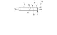
- FIG. 1 is a schematic diagram showing a flavor inhalation article according to a first embodiment.
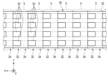
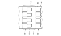
- FIG. 2 is a schematic diagram showing a portion of a sheet material for forming a filter assembly (rod assembly) which is the basis for the filter segment (rod segment) of the flavor inhalation article shown in FIG.
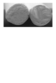
- the left-hand view of Figure 3 is a view of the holeless region of the filter material, for example, the mouth end (rear end surface) of the filter segment of the flavor inhalation article shown in Figure 1
- the right-hand view of Figure 3 is a view of the punched region of the filter material, for example, the tip end surface of the filter segment.
- FIG. 1 is a schematic diagram showing a flavor inhalation article according to a first embodiment.
- FIG. 2 is a schematic diagram showing a portion of a sheet material for forming a filter assembly (rod assembly) which is the basis for the filter segment (rod segment) of the flavor inhalation article shown in FIG.
- the left-hand view of Figure 3 is a
- FIG. 4 is a schematic diagram showing a manufacturing apparatus for manufacturing a filter assembly that serves as a base for the filter segments of the flavor inhalation article according to the first embodiment.
- FIG. 5A is a schematic diagram showing a state in which a sheet material is disposed between crepe rollers in the creping section (crimping section) of the production apparatus shown in FIG.
- FIG. 5B is a schematic diagram showing a state in which the distance between the rotation axes of the crepe rollers of the crepe unit is narrowed from the state shown in FIG. 5A.
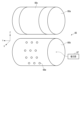
- 6A is a schematic perspective view showing upper and lower rollers of the punching unit of the manufacturing apparatus shown in FIG. 4.
- FIG. 6B is a schematic diagram showing a flexible sheet being magnetically attached to the upper roller of the punching section shown in FIG. 6A.
- FIG. 6C is a schematic cross-sectional view taken along line 6C-6C shown in FIG. 6B.
- FIG. 7 is a schematic perspective view showing an example of upper and lower rollers of the punching unit of the manufacturing apparatus shown in FIG. 4, which is different from that shown in FIG. 6A.
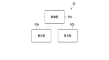
- FIG. 8 is a schematic block diagram of an optical inspection device of the manufacturing apparatus shown in FIG.
- FIG. 9 is a schematic diagram showing a state of the filter assembly when the light transmittance is inspected by the optical inspection device shown in FIG. FIG.
- FIG. 10 is a schematic diagram showing one segment of a sheet material for manufacturing a flavor inhalation article according to a first modified example of the first embodiment.
- FIG. 11 is a schematic diagram showing one segment of a sheet material for manufacturing a flavor inhalation article according to a second modified example of the first embodiment.
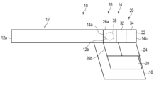
- FIG. 12 is a schematic diagram showing a flavor inhalation article according to a third modified example of the first embodiment.
- FIG. 13A is a schematic diagram showing a flavor inhalation article according to a fourth modified example of the first embodiment.
- FIG. 13B is a schematic diagram showing a flavor inhalation article according to a further modified example of the fourth modified example of the first embodiment.
- FIG. 14 is a schematic diagram showing a portion of a sheet material that is the basis of the filter segment of the flavor inhalation article shown in FIG. 1 according to a fifth modified example of the first embodiment and is used to form a filter assembly having different performance from the sheet material shown in FIG. 2.
- FIG. 15A is a schematic diagram showing a flavor inhalation article according to a second embodiment.
- FIG. 15B is a schematic diagram showing a state in which a first additive (liquid) is added (applied) to a predetermined region of a sheet material that is the base of a filter segment of a flavor inhalation article according to the second embodiment.
- FIG. 16 is a schematic diagram showing a state in which a first additive (liquid) and/or a second additive (liquid) is added (applied) to a predetermined region of a sheet material that is the basis of a filter segment of a flavor inhalation article according to a second embodiment.
- FIG. 17 is a schematic diagram showing a flavor inhalation article according to the third embodiment.
- FIG. 1 First Embodiment The first embodiment will be described with reference to FIGS. 1 to 9.
- the flavor inhalation article 10 has a flavor generating segment (rod segment) 12, a mouthpiece segment (rod segment) 14 provided downstream of the flavor generating segment 12, and tipping paper 16 connecting the flavor generating segment 12 and the mouthpiece segment 14.
- the flavor generating segment 12 and the mouthpiece segment 14 are preferably each formed as a rod having a substantially cylindrical shape (a substantially circular cross section). In other words, the flavor generating segment 12 and the mouthpiece segment 14 are each a rod or a rod segment.
- the filter segment 20, tip plug 42, flavor generating section 44, etc., described below, are also rods or rod segments.
- the flavor inhalation article 10 may be a non-combustion, heating type product that heats the flavor generating segment 12 without burning it, or a combustion type product that burns the flavor generating segment 12.
- the flavor inhalation article 10 may also be a non-combustion, non-heating type product.
- the flavor generating segment 12 is formed into a cylindrical rod by wrapping a suitable filling material in wrapping paper. Various filling materials can be used.
- tobacco shreds can be used as the filling material for the non-combustion heating flavor generating segment 12.
- tobacco shreds obtained by cutting dried tobacco leaves to a width of 0.8 mm to 1.2 mm may be filled into the cigarette paper.
- Dried tobacco leaves may also be crushed and homogenized to an average particle size of about 20 ⁇ m to 200 ⁇ m, processed into a sheet material, and then cut into a width of 0.8 mm to 1.2 mm and filled into the cigarette paper.
- the sheet material may be gathered, folded, or spirally wound without being cut into pieces and filled into the cigarette paper.
- the sheet material may be cut into strips and filled into the cigarette paper concentrically or with the longitudinal direction of the strips parallel to the longitudinal direction of the rod of the flavor generating segment 12.
- the flavor generating segment 12 may generate an aerosol when heated.
- an aerosol source such as a polyol, such as glycerin, propylene glycol, or 1,3-butanediol, as part of the filling.
- the amount of the aerosol source added is preferably 5% to 50% by weight, more preferably 10% to 30% by weight, based on the dry weight of the filling.
- the flavor generating segment 12 may contain a flavoring such as menthol.
- tobacco shreds obtained by cutting dried tobacco leaves to a width of 0.8 mm to 1.2 mm may be filled into the cigarette paper.
- dried tobacco leaves may be crushed and homogenized to an average particle size of about 20 ⁇ m to 200 ⁇ m, processed into a sheet material, and then cut into a width of 0.8 mm to 1.2 mm and filled into the cigarette paper.
- the sheet material may be gathered, folded, or spirally wound without being cut into pieces, and filled into the cigarette paper.
- the sheet material may be cut into strips, and these may be filled into the cigarette paper concentrically, or with the longitudinal direction of the strips parallel to the longitudinal direction of the tobacco rod.
- the length of the rod of the flavor generation segment 12 can be set as appropriate.
- the length of the rod of the flavor generation segment 12 is preferably, for example, 15 mm to 70 mm.
- the diameter of the rod of the flavor generation segment 12 is approximately constant from the tip face (the end face of the flavor generation segment 12 opposite the mouth end 14b) 12a to the rear end face 12b, and can be set as appropriate.
- the diameter of the rod of the flavor generation segment 12 is preferably, for example, 4 mm to 10 mm, and more preferably 6 mm to 8 mm.
- the mouthpiece segment 14 has a filter segment (rod segment) 20.
- the sheet material 30 of the filter segment 20 can be, for example, a paper material, a nonwoven fabric material, a resin material, or the like, processed into a cylindrical shape.
- the filter segment 20 performs functions such as adjusting the amount of air mixed in when the user inhales aerosols, reducing the smoking taste, and reducing nicotine and tar.
- the filter segment 20 does not need to have all of these functions.
- the filter segment 20 can suppress the filtering function while preventing the tobacco filling from falling.
- the mouthpiece segment 14 When the mouthpiece segment 14 is formed as a part of the non-combustion heating type flavor inhalation article 10, it may have a cooling segment 46. This will be described later in the second modified example of the second embodiment (see FIG. 17). That is, in this embodiment, the mouthpiece segment 14 and the filter segment 20 will be described as being the same thing.
- the length of the rod of the mouthpiece segment 14 is preferably, for example, 10 mm to 50 mm, and more preferably, approximately 25 mm to 30 mm.
- the diameter of the rod of the mouthpiece segment 14 is approximately constant from the tip surface 14a to the rear end surface (mouth end) 14b, and is preferably, for example, 4 mm to 10 mm, and more preferably, 6 mm to 8 mm.
- the diameter of the flavor generating segment 12 and the diameter of the mouthpiece segment 14 are the same or approximately the same, and the tipping paper 16 is wrapped around the outer circumference including the rear end surface 12b of the flavor generating segment 12 and the tip surface 14a of the mouthpiece segment 14 with the rear end surface 12b of the flavor generating segment 12 and the tip surface 14a of the mouthpiece segment 14 butted against each other.
- a flavor inhalation article 10 is formed in which the rods of the flavor generating segment 12 and the rods of the mouthpiece segment 14 are aligned in the axial direction.
- the filter segment 20 includes a filter material 22 and a wrapper 24 that is wrapped around the outside of the filter material 22 and forms the filter segment 20 into a rod.
- the filter material 22 of the filter segment 20 is formed by processing a sheet material 30 shown in Figure 2, which has a punched region (first segment) 32 that is partially punched out and a holeless region (second segment) 34 that is not punched out.
- the punched region 32 and the holeless region 34 are disposed adjacent to each other in the longitudinal direction (axial direction) of the sheet material 30.
- the filter material 22 of the filter segment 20 is formed by processing one segment S of the sheet material 30, which has the punched region 32 and the holeless region 34.
- the filter segment 20 is formed from a filter assembly (rod assembly) 18 having a length, for example, four or six times that of the filter segment 20 to be actually used, by a rod manufacturing device 50 described later.
- the filter segment 20 is formed by cutting the filter assembly 18 to a predetermined length at a predetermined position. That is, the filter segment 20 is formed by, for example, cutting in two stages. The first stage is a process of cutting the filter assembly 18, which is made by crimping a continuous sheet material 30 and wrapping it with a wrapper 24, to a length, for example, four or six times that of the filter segment 20 to be actually used as a part of the flavor inhalation article 10.
- the second stage is a process of cutting the filter segment 20 having a length four or six times the desired length to the length of the filter segment 20 to be actually used as a part of the flavor inhalation article 10. Therefore, by cutting the filter assembly 18 in the second stage, four or six filter segments 20 are formed from the filter assembly 18. The cutting of the filter assembly 18 in the second stage may be performed by multiple cuts.
- FIG. 2 defines an XYZ Cartesian coordinate system.
- the direction along the X axis is the axial direction of the sheet material 30 (the longitudinal direction before being cut) and the conveying direction.
- the direction along the Y axis is the width direction of the sheet material 30.
- the direction along the Z axis is the thickness direction of the sheet material 30.
- the filter material 22 is formed by processing the sheet material 30 shown in Fig. 2.
- the filter material 22 is formed, for example, by processing a sheet material made of paper, a sheet material made of nonwoven fabric, or a sheet material 30 made of resin.
- a sheet material made of paper that is, an example as a paper filter
- the sheet material made of paper 30 is, for example, paper obtained by papermaking wood pulp.
- the paper filter is a biodegradable filter in which the paper sheet material 30 is used as the filter material 22 and the outside of the filter material 22 is wrapped with wrapping paper 24 to form a rod shape, and is an excellent biodegradable filter.
- the width of the sheet material 30 in the width direction is formed to an appropriate size, for example, between 150 mm and 250 mm. This is adjusted according to the thickness of the sheet material 30, the diameter of the filter segment 20 to be manufactured, and the like. Furthermore, when a tobacco sheet material or a cooling sheet material is used as the sheet material 30, as described below, the material, width in the width direction, and thickness of the sheet material 30 are adjusted according to the function.
- punched regions 32 and holeless regions 34 are alternately, i.e., repeatedly, formed along the longitudinal direction of the sheet material 30.
- the sheet material 30 is repeatedly formed with segments S, each of which is a pair of one punched region 32 and a holeless region 34 adjacent to the punched region 32.
- the longitudinal direction of the sheet material 30 is the direction along which the punched regions 32 and the holeless region 34 are adjacently arranged.
- the width direction of the sheet material 30 is a direction intersecting the direction in which the punched regions 32 and the holeless region 34 are adjacently arranged, and is preferably perpendicular to this direction.
- the length of the rod of the filter segment 20 is formed as the length of one segment S of the sheet material 30, which is, for example, the combined length of one punched region 32 and one holeless region 34.
- the holeless region 34 of the sheet material 30 is formed as a closed region (partition) that has no holes penetrating in the Z-axis direction at any position in the region defined by the longitudinal and transverse directions of the sheet material 30.
- the punched regions 32 form a plurality of openings (opening edges) 33 penetrating the sheet material 30 in the Z-axis direction.
- a plurality of openings 33 of the same shape are formed at intervals in the width direction.
- the plurality of openings 33 are formed as substantially rectangular holes of the same shape and size at equal intervals in the width direction.
- the shape of the openings 33 may be a substantially rectangular shape, or may be a substantially polygonal shape, a substantially circular shape, a substantially elliptical shape, or any other suitable shape. It is preferable that the edges of the plurality of openings 33 do not have corners.
- the opening 33 may be formed at both ends of the sheet material 30 in the width direction, it is preferable that no opening 33 is formed at both ends of the sheet material 30 in the width direction in order to prevent the sheet material 30 from getting caught on, for example, the focusing guide 74 (see FIG. 4) of the rod manufacturing device 50 when forming the sheet material 30 into a rod.
- the punching range of the punching region 32 in the sheet material 30 (the area inside the opening 33) is arbitrary. However, if punching is performed too much, the filter material (solid part) will be small when the sheet material 30 is made into the rod of the filter segment 20, and the hardness of the filter segment 20 as a rod will decrease. Furthermore, if the filter material (solid part) is small, the strength of the filter segment 20 as a rod will decrease, and the manufacturing suitability during manufacturing may decrease.
- the punching range of the punching region 32 of the sheet material 30 is, for example, about 5% to 70%, preferably about 10% to 50%, of the area of the region defined by the longitudinal direction and width direction of the sheet material 30 when the sheet material 30 is spread out.
- the lower limit of the range of the punching region 32 (whether the punching region 32 leaves a large area of the solid part of the sheet material 30) can vary depending on how low the filterability is desired by the manufacturer of the filter segment 20.
- the upper limit of the punching range of the punching region 32 (whether the openings 33 of the punching region 32 reduce the area of the solid part of the sheet material 30) can vary depending on how hard the manufacturer of the filter segment 20 desires for the filter segment 20 and on the manufacturing suitability.
- the length ratio between the holeless region 34 and the punched region 32 is adjusted as appropriate, for example, in the range of 1:5 to 5:1, or in the range of 2:3 to 3:2.
- the length ratio between the holeless region 34 and the punched region 32 may be 1:1, i.e., the same length.
- the length ratio between the holeless region 34 and the punched region 32 can be set as appropriate by the manufacturer of the flavor inhalation article 10.
- One segment S of the sheet material 30 forms the filter material 22 of the filter segment 20.
- One segment S of the sheet material 30 is creped (shrinked) such as gathered and folded in the width direction (Y-axis direction) of the sheet material so that the longitudinal direction of the rod of the filter segment 20 is aligned with the direction in which the punched area 32 and the holeless area 34 are adjacently arranged, and a cylindrical rod is formed from the filter material 22. That is, a large number of streaks are formed along the X-axis direction, and the width of one segment S of the sheet material 30 in the width direction is reduced by folding these streaks in the mountain and valley directions, and a cylindrical rod is formed from the filter material 22 while maintaining the longitudinal length of one segment S. Then, the filter segment 20 is formed as a cylindrical rod or rod segment by wrapping the outer periphery of the cylindrical filter material 22 with a wrapper 24.
- FIG. 3 is a view of the holeless region 34 of the filter material 22 as the end face of the filter segment 20, and the right side of FIG. 3 is a view of the punched region 32 of the filter material 22 as the end face of the filter segment 20.
- the end face of the filter material 22 on the holeless region 34 side shown in the left side of FIG. 3 is "loose", i.e., has smaller holes, than the end face of the filter material 22 on the punched region 32 side shown in the right side of FIG. 3.
- the filter material 22 is lower in the punched region 32 along the axial direction of the rod of the filter segment 20 than in the holeless region 34, and is formed as a region of low airflow resistance.
- the filter material 22 is higher in the holeless region 34 along the axial direction of the rod of the filter segment 20 than in the punched region 32, and is formed as a region of high airflow resistance. Therefore, by arranging the punched area 32 and the holeless area 34 adjacently along the axial direction of the rod of the filter segment 20, an area with relatively low airflow resistance and an area with relatively high airflow resistance are formed in the filter material 22 of one segment S of one sheet material 30. Therefore, it is possible to form a plurality of areas with different filtering performance, such as two, along the axial direction of the rod of the filter segment 20 using one filter material 22, while wrapping the outer periphery of the sheet material 30 with one wrapper 24 to maintain the rod shape of the filter segment 20.
- the filter segment 20 has the mouth end 14b of the flavor inhalation article 10 formed in the holeless region 34 (left side view in Figure 3) of the filter material 22. That is, along the axial direction of the filter segment (rod) 20, the punched-out region 32 is arranged upstream of the holeless region 34 (flavor generating segment 12 side).
- the holeless region 34 i.e., the high filtration region, is arranged at a position including the mouth end 14b of the filter segment 20, and the punched-out region 32 is arranged at a position away from the mouth end 14b toward the flavor generating segment 12 side.
- the filter segment 20 can be made to have less "looseness", i.e., less holes, on the mouth end 14b side, and the appearance can be improved when a user looks at the mouth end 14b of the mouthpiece segment 14 of the flavor inhalation article 10.
- the filter segment 20 can adjust the airflow resistance at a position along the longitudinal direction with one member (the filter material 22 of one segment S of the sheet material 30), and can form an area of low airflow resistance due to the presence of the punched area 32.
- a flavor inhalation article 10 equipped with such a filter segment 20 can be provided.
- the airflow resistance of the filter material 22 of the filter segment 20 not only depends on the selection of the sheet material 30, but can also be adjusted by, for example, setting the crepe depth (see FIGS. 5A and 5B ) by a pair of crepe rollers 64 a, 64 b in the crepe section (crimping section) 64 of the manufacturing apparatus 50 (see FIG. 4 ), which will be described later.
- the difference in air flow resistance per mm of the rod of the filter segment 20 between the first segment (punched region) 32 and the second segment (holeless region) 34 is 0.5 mmH 2 O/mm to 10 mmH 2 O/mm, and preferably 1 mmH 2 O/mm to 5 mmH 2 O/mm.
- wrapping paper can be used for the wrapper 24.
- wrapping paper with a larger basis weight may be used.
- the basis weight of the wrapper 24 is preferably 30 gsm or more, more preferably 50 gsm, and even more preferably 100 gsm or less.
- the tipping paper 16 may be thickened.
- an XYZ Cartesian coordinate system is defined, similar to the sheet material 30 shown in FIG. 2.
- the X-axis direction is the direction in which the sheet material 30 is transported from the feed section 62 to the cutting section 58, which will be described later.
- the manufacturing apparatus 50 for the rods for the flavor inhalation article 10 has a supply section 52 for the sheet material 30, a processing section 54 for the sheet material 30, a rod forming section (rod winding section) 56, a rod cutting section 58, and a rod optical inspection device (inspection unit) 60.
- the supply section 52, processing section 54, rod forming section 56, rod cutting section 58, and optical inspection device 60 are controlled by a control device (not shown). It is preferable that the control device of the manufacturing apparatus 50 appropriately controls the supply section 52, processing section 54, rod forming section 56, and rod cutting section 58, for example by feedback control, based on information from a control section 60c of the optical inspection device 60, which will be described later.
- control device of the manufacturing device 50 controls at least one of the following based on information from the control unit 60c of the optical inspection device 60, which will be described later: the supply of the sheet material 30 by the supply unit 52, the crimping of the sheet material 30 by the creping unit (crimping unit) 64 of the processing unit 54, which will be described later, the punching of the sheet material 30 by the punching unit 66, which will be described later, the formation of the rod by the rod forming unit 56, and the cutting of the rod by the rod cutting unit 58.
- the supply unit 52 supplies and conveys the holeless sheet material 30, or the sheet material 30 on which the punched area 32 and the holeless area 34 have been formed in advance, in a predetermined direction.
- the supply unit 52 has a bobbin 52a, a dancer unit 52b, and an auxiliary roller 52c.
- the bobbin 52a has a holeless sheet material 30 with no punched area 32 (opening 33) formed therein wound around the axis of a shaft 52a1 parallel to the Y-axis direction, for example.
- the original length of the sheet material 30 (the length of the sheet material 30 wound around the bobbin 52a) is formed to an appropriate length, such as 50 m to 100 m or more.
- the sheet material 30 is unwound in a predetermined direction (dancer unit 52b) from the bobbin (raw paper roll) 52a, which rotates with the rotation of the shaft 52a1.
- the sheet material 30 is unwound in the longitudinal direction of the sheet material 30 while the movement of the sheet material 30 in the longitudinal direction is controlled, for example, at a constant speed and constant tension.
- the dancer unit 52b is provided downstream of the bobbin 52a of the supply section 52 and upstream of the feed section 62 of the processing section 54, which will be described later.
- the dancer unit 52b adjusts the sheet material 30 so as to reduce changes in the tension of the sheet material 30 caused by changes in the diameter of the bobbin 52a, changes in the feed speed of the sheet material 30, etc.
- the dancer unit 52b has multiple upper rollers 52b1 and multiple lower rollers 52b2.
- the sheet material 30 is passed in a zigzag pattern between the upper and lower rollers 52b1, 52b2 of the dancer unit 52b.
- An auxiliary roller 52c is provided downstream of the dancer unit 52b.
- the auxiliary roller 52c changes the direction of the sheet material 30 that has passed through the dancer unit 52b toward the feed section 62, which will be described later.
- the processing section 54 performs preliminary work to form the sheet material 30 into a rod, and also forms an area for changing the air flow resistance in one segment S.
- the processing section 54 has a feed section 62, a creping section 64, a punching section 66, an auxiliary roller 54a, and an addition section 68 along the flow of the sheet material 30, which is made of, for example, paper.
- the feed section 62 moves the sheet material 30 downstream while the sheet material 30 has an appropriate tension in the X-axis direction.
- the feed section 62 has, for example, a pair of feed rollers 62a, 62b.
- the upper roller 62a of the feed section 62 is formed, for example, of two rubber rollers arranged side by side, that is, in the depth direction of the paper surface in FIG. 4.
- the lower roller 62b is formed, for example, of a metal roller with a flat surface.
- a spiral is formed on the surface of the two rubber rollers of the upper roller 62a, and when the feed rollers 62a, 62b rotate, the two ends of the sheet material 30 in the width direction are spread apart in the horizontal direction (Y-axis direction), preventing the occurrence of unintended wrinkles at this point.
- a creping section (crimping section) 64 is provided downstream of the feed section 62 for creping the sheet material 30.
- the creping section 64 crimps the sheet material 30 conveyed from the supply section 52.
- the creping section 64 has a pair of creping rollers 64a, 64b.
- the creping rollers 64a, 64b are used to form vertical wrinkles in the sheet material 30 along the X-axis direction, which makes it easier to form the filter segments 20 into rods.
- the creping section 64 creates streaky crimps along the longitudinal direction of the sheet material 30, making it easier to fold the sheet material 30 when forming it into a rod.
- a pair of crepe rollers 64a, 64b have rotating shafts 6411, 6421 parallel to each other in the Y-axis direction, and multiple convex portions (disk-shaped members) 6412, 6422.
- the upper rotating shaft 6411 is the first rotating shaft
- the lower rotating shaft 6421 is the second rotating shaft.
- the first rotating shaft 6411 is provided with multiple first convex portions 6412
- the second rotating shaft 6421 is provided with multiple second convex portions 6422.
- the multiple convex portions 6412, 6422 are each formed as a disk-shaped member of the same diameter. Adjacent convex portions 6412, 6422 are spaced apart, for example, at a predetermined interval in the width direction (Y-axis direction) of the sheet material 30.
- the first rotating shaft 6411 and the second rotating shaft 6421 can be moved closer to or farther away from each other while maintaining a parallel state in the width direction (Y-axis direction) of the sheet material 30.
- the multiple first convex portions 6412 protrude from the first rotating shaft 6411 by approximately the same amount.
- the multiple first convex portions 6412 are spaced apart at a predetermined interval in the width direction.
- the multiple second convex portions 6422 protrude from the second rotating shaft 6421 by approximately the same amount.
- the multiple second convex portions 6422 are spaced apart at a predetermined interval in the width direction.
- the distance between the top 6412a of the first convex portion 6412 and the top 6422a of the second convex portion 6422 along the approach and separation direction of the first rotation shaft 6411 and the second rotation shaft 6421 is defined as the meshing amount.
- the distances D1 and D2 are preferably set to, for example, about 1 mm or less.
- the crepe depth can be replaced with the distance in the Z-axis direction between the tops 6412a and 6422a of the convex portions 6412 and 6422 of the pair of crepe rollers 64a and 64b. Comparing the distance D1 in FIG. 5A with the distance D2 in FIG. 5B, the distance D2 is larger. At this time, the crepe depth of the sheet material 30 is greater in the example shown in FIG. 5B than in the example shown in FIG. 5A. During the creping process of the sheet material 30, the positional relationship between the first rotating shaft 6411 and the second rotating shaft 6421 of the creping unit 64 is fixed.
- the meshing depth (distances D1, D2) between the protrusions 6412, 6422 is adjusted, and the depth of the vertical wrinkles along the X-axis direction formed in the sheet material 30 or the degree of stretching of the sheet material 30 changes.
- the meshing depth between the protrusions 6412, 6422 the airflow resistance in one segment S of the filter material 22 can be adjusted.
- the pair of crepe rollers 64a, 64b do not need to rotate around the rotation shafts 6411, 6421 as long as the sheet material 30 slides between the apex 6412a of the first convex portion 6412 and the apex 6422a of the second convex portion 6422 and moves downstream. For this reason, the pair of crepe rollers 64a, 64b of the crepe section 64 may each be formed as a crepe tool.
- a punching section 66 is disposed downstream of the creping section 64.
- the punching section 66 punches out a portion of the sheet material 30 transported (supplied) from the supply section 52.
- the punching section 66 punches out a portion of the sheet material 30 to form a plurality of openings 33, thereby forming a punched region 32 and a holeless region 34.
- the punching section 66 is described as being disposed downstream of the creping section 64 along the transport direction of the sheet material 30. It is also preferable that the punching section 66 is disposed upstream of the creping section 64.
- the positional relationship between the punching section 66 and the creping section 64 may be either the upstream side or the downstream side, but it is preferable that the creping section 64 is upstream and the punching section 66 is downstream.
- the sheet material 30 passes through the creping section 64, the sheet material 30 stretches. For this reason, by punching the sheet material 30 with the punching section 66 after the sheet material 30 has been stretched, it is easy to control the punching position.
- the punching section 66 is located upstream of the creping section 64, sufficient tension is applied to the sheet material 30 during transport, making it easy to punch the openings 33.
- the punching unit 66 has, for example, an upper roller (first roller) 66a and a lower roller (second roller) 66b.
- the punching unit 66 forms a plurality of openings 33 of a predetermined size and shape in the sheet material 30 as the sheet material 30 passes between the upper and lower rollers 66a, 66b.
- a sheet material 30 (see FIG. 2) having a punched area 32 and a holeless area 34 is formed.
- the upper roller 66a has a blade (see FIG. 6C) that appropriately cuts the sheet material 30.
- the lower roller 66b is formed, for example, as a metal roll with no irregularities.
- the sheet material 30 is conveyed between the upper roller 66a and the lower roller 66b, and as it is clamped, the blade punches out the sheet material 30 to sequentially form predetermined openings 33.
- sets (segments S) of punched areas 32 and holeless areas 34 are repeatedly formed in the sheet material 30.
- the blade is formed so that the punched piece of paper has no corners. That is, the blade is formed so that it punches out the opening 33 in a circular shape without corners. Therefore, the blade of the punching portion 66 prevents the punched piece of paper from remaining connected to the sheet material 30.
- Figure 6A shows the first example (a method using a flexible die 66c).
- Figure 7 shows the second example (a method using a rotary die).
- the punching section 66 shown in FIG. 6A has an upper roller (punching roller) 66a made of, for example, a metal material to which a flexible die 66c (see FIG. 6B) is magnetically attached, and a lower roller (anvil roller) 66b.
- the flexible die 66c is formed by etching or machining a thin metal sheet, for example, about 0.45 mm, and a cutting blade 66d formed in the shape of the opening 33 is provided on the surface of the metal sheet to punch the opening 33.
- the flexible die 66c is magnetically attached to the magnetic upper roller 66a.
- two flexible dies 66c are attached to the upper roller 66a.
- two flexible dies 66c are used adjacent to each other in the circumferential or axial direction of the upper roller 66a. Then, the entire upper roller 66a is covered with the flexible die 66c.
- the flexible die 66c may be set relative to the upper roller 66a so that the punching area 32 and the holeless area 34 are repeatedly formed in the same shape along the longitudinal direction of the sheet material 30.
- the lower roller (anvil roll) 66b is preferably formed with a number of holes 66e communicating with the suction section (suction source) 67 as a punched piece removal section that removes punched pieces of the sheet material 30 that have been partially punched out by the punching section 66. That is, the numerous holes (punched piece removal section) 66e are provided within the punching section 66. These holes 66e are preferably arranged according to the shape of the opening 33 to be punched out.
- the cutting blade of the flexible die 66c which is formed in the shape of the opening 33
- the periphery of the hole 66e of the lower roller 66b sandwich the sheet material 30 to form the opening 33 in the sheet material 30, and the paper piece in the shape of the punched opening 33 is adsorbed around the hole 66e.
- the piece of paper in the shape of the opening 33 that is attracted to the periphery of the hole 66e is released from the attraction when it is moved below the lower roller (anvil roll) 66b, so that it falls off the lower roller 66b at a predetermined location and is collected in a tray (not shown) or the like that serves as a punched piece removal section.
- the upper roller 66a is formed as a rotary die.
- the upper roller (rotary die) 66a is formed with a predetermined cutting blade 66f for forming the opening 33 in the sheet material 30, for example, by cutting out a metal roll.
- the upper roller 66a can be used for relatively thick sheet material 30.
- the upper roller (rotary die) 66a can be reused by re-grinding the cutting blade 66f.
- holes 66g of the same size as or slightly smaller than the punched pieces of paper are formed inside the cutter blade 66f of the upper roller (rotary die) 66a as a punched piece removal section. These holes 66g are connected to the suction section (suction source) 67. That is, when the vicinity of the bottom surface of the upper roller 66a faces the vicinity of the top surface of the lower roller 66b, the cutter blade 66f formed in the shape of the opening 33 and the lower roller 66b sandwich the sheet material 30 to form the opening 33 in the sheet material 30, and the punched pieces of paper in the shape of the opening 33 are collected in the upper roller (rotary die) 66a through the holes 66g.
- the collected pieces of paper are removed, for example, along the rotation axis of the upper roller 66a.
- a separation section that separates the pieces of paper from the air flow caused by suction may be provided between the hole 66g and the communication path of the suction section (suction source) 67.
- the lower roller (anvil roll) 66b shown in FIG. 7 may also be provided with a hole 66e (punched piece removal section) that communicates with the suction section 67.
- the paper pieces in the shape of the opening 33 that are adsorbed around the hole 66e are released from adsorption to the paper pieces when they are moved below the lower roller (anvil roll) 66b, so that they fall off the lower roller 66b at a predetermined location and are collected in a tray (not shown) or the like that serves as a punched piece removal section.
- a suction section (suction source) 67 may be installed downstream of the punching section 66 as a punched piece removal section to collect the paper pieces.
- punched paper pieces adhering to the sheet material 30 can be more reliably removed.
- compressed air may be sprayed from the top of the sheet material 30, and suction may be performed at the bottom of the sheet material 30 to collect the paper pieces.
- an addition section 68 is disposed downstream of the punching section 66.
- the addition section 68 has a liquid addition section 68a and a granule addition section 68b.
- the addition section 68 may add an additive to the filter material 22 when the filter material 22 of the sheet material 30 is creped, for example, to form it into a cylindrical rod.
- the additive may be a liquid, granules (solid), or both. Note that the addition section 68 is not used in this embodiment. For this reason, the sheet material 30 passes directly through the liquid addition section 68a and granule addition section 68b of the addition section 68.
- the addition section 68 will be described in the second embodiment (see FIGS. 15A-16B).
- the rod forming section 56 is disposed downstream of the adding section 68. That is, the rod forming section 56 is disposed downstream of the punching section 66 and the creping section 64.
- the rod forming section 56 forms the sheet material 30 into a rod having a substantially circular cross section, i.e., a substantially cylindrical appearance, in which punched regions 32 and holeless regions 34 are alternately arranged along the axial direction.
- the rod forming section 56 has a roll paper supply mechanism 72, a focusing guide 74, a wrap glue gun 76, and tongs 78.
- the roll paper supply mechanism 72 supplies the sheet-like member 24a, which is supplied from a bobbin 72a around which the sheet-like member 24a is wound, to the focusing guide 74 together with the sheet material 30.
- the sheet-like member 24a becomes the wrapper 24 around which the filter material 22 is wound when the filter segment 20 is formed.
- the focusing guide 74 is formed so that the diameter of the passage narrows from the upstream to the downstream side.
- the focusing guide 74 brings the sheet material 30 closer to a cylindrical rod as it passes through the focusing guide 74.
- the focusing guide 74 narrows the width through which the sheet material 30 passes from the upstream to the downstream side, and deforms the sheet material 30 into an approximately bellows shape according to the vertical wrinkles (striated tendencies) formed by the crepe section 64.
- the sheet material 30 is regularly narrowed, and the shape of the sheet material 30 approaches a cylindrical rod.
- the focusing guide 74 wraps the outer periphery of the sheet material 30 that has been brought closer to the rod with the sheet-like member 24a. In other words, the focusing guide 74 brings the narrowed sheet material 30 (filter material 22) closer to a cylindrical rod shape while surrounding the outer periphery with the sheet-like member 24a that becomes the wrapper 24.
- glue is applied from a wrap glue gun 76 to the widthwise end surface of the sheet-like member 24a that has passed through the focusing guide 74.
- Tongs 78 are provided downstream of the wrap glue gun 76.
- the tongs 78 join the end faces of the sheet-like member 24a that will become the wrapper 24. Therefore, the tongs 78 maintain the shape of the filter assembly 18 that can be formed into the filter segment 20.
- the rod forming section 56 of the manufacturing device 50 can wind up the sheet material 30 with the sheet-like member 24a that will become the wrapper 24 as a filter assembly (rod assembly).
- the cutting unit 58 sequentially cuts the continuous rod wound up by the tongs 78 to a predetermined length. At this time, the cutting unit 58 cuts the rod into a state having at least one punched region 32 and one holeless region 34. Therefore, the manufacturing device 50 can manufacture a filter assembly 18 of a predetermined length. Note that in this embodiment, an example is described in which the cutting unit 58 manufactures a filter assembly 18 of a predetermined length, such as four or six times the length of the filter segment 20, but the filter segment 20 may be manufactured directly from the continuous rod-shaped member wound up by the tongs 78 without manufacturing the filter assembly 18.
- An optical inspection device 60 for the rod of the filter assembly 18 is provided downstream of the cutting section 58.
- the optical inspection device 60 has a light-emitting unit 60a, a light-receiving unit 60b that receives light irradiated from the light-emitting unit 60a and passing through the filter assembly (rod) 18, and a control unit 60c that controls the light-emitting unit 60a and the light-receiving unit 60b.
- the light-emitting unit 60a is a light source such as an LED light source.
- the light-receiving unit 60b is a detector that detects light, such as an imaging element of a camera or a photodiode.
- the control unit 60c is a computer, and physically includes memories such as RAM and ROM, a processor (arithmetic circuit) such as a CPU, a communications interface, and an information storage unit such as a hard disk. Examples of the control unit 60c include a personal computer, a cloud server, and a tablet terminal. The control unit 60c functions by executing a program stored in the memory with the processor.
- the control unit 60c When a camera is used as the light receiving unit 60b, the control unit 60c outputs, for example, a pixel value (light intensity) for each pixel based on the light information (light receiving information) received by the light receiving unit 60b.
- the filter assembly 18 has a different amount of sheet material 30 along the longitudinal direction in the punched area 32 where the sheet material 30 is punched and in the holeless area 34 where the sheet material 30 is not punched, resulting in a difference in transmitted light intensity. That is, each filter assembly 18 has a first light transmitting portion 18a and a second light transmitting portion 18b having a lower light transmittance than the first light transmitting portion 18a repeated.
- the first light transmitting portion 18a corresponds to the punched area 32
- the second light transmitting portion 18b corresponds to the holeless area 34. Therefore, the control unit 60c can recognize the boundaries between the punched regions 32 and the holeless regions 34 of the filter material 22 in the filter assembly 18 based on the intensity of light (light reception information) received by the light receiving unit 60b through the filter assembly 18 from the light emitting unit 60a.
- the filter assembly 18 can be inspected by the optical inspection device 60 that inspects such transmitted light intensity. Therefore, the control unit 60c can output the position and length of the first light transmitting portion 18a (punched region 32) and the position and length of the second light transmitting portion 18b (holeless region 34) between one end and the other end of the filter assembly 18.
- the control unit 60c outputs whether or not the plurality of punched regions 32 and the plurality of holeless regions 34 are set to the desired lengths that have been previously set. If the control unit 60c detects the punching regions 32 and the holeless regions 34 as being the desired lengths set in advance, for example, the control device of the manufacturing device 50 controls (feedback control) each device of the manufacturing device 50 (the supply unit 52, the processing unit 54, the rod forming unit 56, the rod cutting unit 58, etc.) to maintain the control state.
- control unit 60c detects the punching regions 32 and the holeless regions 34 as being out of the desired lengths set in advance
- the control device of the manufacturing device 50 controls (feedback control) the control state of each device of the manufacturing device 50 so that the punching regions 32 and the holeless regions 34 are the desired lengths set in advance.
- the control unit 60c controls the supply of the sheet material 30 by the supply unit 52 of the sheet material 30 and the punching of the sheet material 30 by the punching unit 66 based on the signal sent from the light receiving unit 60b to the control unit 60c.
- the light emitted from the light-emitting unit 60a and received by the light-receiving unit 60b through the sheet-like member 24a, the rod-shaped filter material 22, and the sheet-like member 24a of the punched area 32 wrapped in a rod shape with the sheet-like member 24a that becomes the wrapper 24 has a higher light transmittance in the first light-transmitting portion 18a (punched area 32) than in the second light-transmitting portion 18b (holeless area 34).
- the control unit 60c can perform quality control of the cylindrically formed filter material 22 (sheet material 30) as well as the positions and lengths of the multiple punched areas 32 and multiple holeless areas 34 of the filter assembly 18. If the variation in light transmittance in the first light transmitting portions 18a (punchout regions 32) is kept within a predetermined threshold range, the control unit 60c outputs that the substantially cylindrical filter material 22 of the filter assembly 18 is held in the sheet-like member 24a that will become the wrapper 24 with substantially uniform quality.
- the control unit 60c outputs that the filter material 22 of the filter assembly 18 is held in the sheet-like member 24a that will become the wrapper 24 with substantially uniform quality.
- the control unit 60c may cause variation in the filtering performance when the filter segment 20 is formed. For this reason, the control unit 60c outputs that the quality of the filter material 22 of the filter assembly 18 is poor and is held in the sheet-like member 24a that will become the wrapper 24.
- control unit 60c may compare the changes in light intensity between the multiple filter assemblies 18 based on information (light transmittance of the first light transmitting portion 18a and/or the second light transmitting portion 18b) received by the light receiving portion 60b from the light emitting portion 60a. At this time, the control unit 60c can compare the quality between the multiple filter assemblies 18.
- the measurement based on the light emitted by the light-emitting unit 60a and the light received by the light-receiving unit 60b may be performed by, for example, periodically capturing images at appropriate time intervals using an image sensor in a camera and processing the images, or the change in light intensity may be measured continuously.
- control unit 60c can output whether or not the filter assembly 18 is formed in the desired state based on the signal sent from the light receiving unit 60b.
- the optical inspection device 60 can output whether or not the filter assembly 18 is formed in the desired state.
- the quality can be stabilized by feedback controlling each device of the manufacturing apparatus 50 (the supply unit 52, the processing unit 54, the rod forming unit 56, the rod cutting unit 58, etc.). Therefore, the manufacturing apparatus 50 according to this embodiment can manufacture filter assemblies 18 of stable quality.
- the optical inspection device 60 is disposed downstream of the rod cutting section 58, and the filter assembly 18 cut to a predetermined length, such as four or six times the length of the filter segment 20, is inspected.
- the optical inspection device 60 may also be disposed upstream of the rod cutting section 58. In this case, the above-mentioned optical inspection may be performed in a state in which the filter material 22 formed by the tongs 78 is wrapped in the sheet-like member 24a that becomes the wrapper 24.
- Each filter assembly 18 is further cut when it is formed into a filter segment 20 for the flavor inhalation article 10. Therefore, the filter assembly 18 is cut before being connected to the flavor generating segment 12 via the tipping paper 16 to form the filter segment 20.
- the optical inspection device 60 may mark the cutting position on the outer peripheral surface of the sheet-like member 24a of the filter assembly 18, which is the boundary between the punched area 32 and the holeless area 34.
- the device that cuts the filter assembly 18 can easily grasp the cutting position of the filter assembly 18, that is, the position at which the filter assembly 18 is cut to obtain a plurality of filter segments 20. Therefore, by using the inspection results by the optical inspection device 60, the work of detecting the position at which the filter assembly 18 is cut can be reduced in the device that cuts the filter assembly 18.
- the filter segment 20, each having at least one punched region 32 and holeless region 34, is obtained by appropriately cutting the filter assembly 18.
- a plurality of regions having different performance can be formed in one member (sheet material 30), and a filter segment 20 for a flavor inhalation article 10 is formed that can adjust, for example, the amount of filtration of a fluid.
- One end of the filter segment 20 is formed in a holeless region 34 as the suction end 14b of the flavor suction article 10.
- the tip surface 14a of the filter segment 20 is abutted against the rear end surface 12b of the flavor generating segment 12 of the flavor suction article 10, and the region including the tip surface 14a of the filter segment 20 and the rear end surface 12b of the flavor generating segment 12 is wrapped with tipping paper 16 to manufacture the flavor suction article 10.
- a flavor inhalation article 10 and a filter segment 20 for a flavor inhalation article 10 that can adjust the amount of fluid filtration, etc. by forming areas with different performance (punched area 32 and holeless area 34) in a single member (filter material 22).
- a holeless sheet material 30 is wound to form a bobbin 52a, and a punching area 32 is formed by a manufacturing device 50.
- the bobbin 52a may also be formed by winding a sheet material 30 on which a punching area 32 and a holeless area 34 have been formed in advance.
- the filter segment 20 can also be formed using such a sheet material 30 on which a punching area 32 and a holeless area 34 have been formed in advance.
- the punching section 66 in the manufacturing device 50 may not be necessary, or the upper and lower rollers 66a, 66b may be removed.
- the manufacturing apparatus 50 can also manufacture rod assemblies or rod segments for flavor inhalation articles 10 other than the filter segment 20.
- a tobacco sheet material is used as the sheet material 30, a tobacco rod having a punched region 32 with an opening 33 and a holeless region 34 is manufactured.
- the tobacco sheet material is creped in the same manner as the above-mentioned sheet material 30, and wrapped with cigarette paper instead of the wrapper 24 to form a rod of the flavor generating segment 12.
- an acetate tow filter for example, may be used as the filter material 22 of the filter segment 20 instead of treating and using the sheet material 30.
- appropriate additives may be added to the tobacco sheet material serving as the sheet material 30, similar to the additives added to the filter material 22 by an adding section 68 (see FIG. 4) as described below.
- the cooling segment 46 it is also possible to manufacture the cooling segment 46 by using a cooling sheet material 30.
- a manufacturing device 50 capable of manufacturing a rod (rod assembly 18 and rod segments 20 cut from rod assembly 18) for a flavor inhalation article 10 that can form areas with different performance in a single member and adjust the state of a fluid flowing, for example, from upstream to downstream, and a manufacturing method for a rod (rod assembly 18 and rod segments 20 cut from rod assembly 18) for a flavor inhalation article 10.
- the openings 33 in the punched region 32 are formed at equal intervals in the width direction.
- the openings 33 in the punched region 32 may be formed randomly in the width direction.
- the arrangement of the openings 33 in the punched region 32 may be such that the openings 33 are appropriately and uniformly arranged and are not excessively biased when the filter segment 20 is formed as a cylindrical rod segment.
- the filter material 22 of the filter segment 20 has one punched area 32 and two holeless areas 34 as one segment S of the sheet material 30.
- both the tip surface 14a and the suction end 14b of the filter segment 20 can be formed as the holeless area 34.
- one segment S of the sheet material 30 of the filter segment 20 may have two punched regions 32 and one holeless region 34.
- the length of the rod of the filter segment 20 is formed as the length of one segment S of the sheet material 30, for example, the length of one punched area 32 and one holeless area 34 combined.
- the length of the rod of the filter segment 20 may be formed as the length of one punched area 32 and two holeless areas 34 combined as shown in FIG. 10, or may be formed as the length of two punched areas 32 and two holeless areas 34 combined, not shown, and is set as appropriate.
- the range defined as one segment S of the sheet material 30 can be set as appropriate.
- the filter material 22 as the rod of the filter segment 20 can be arranged in various ways, such as “holeless region 34 - punched region 32 - holeless region 34" (see Figure 10) or “punched region 32 - holeless region 34 - punched region 32" (not shown).
- a flavor suction article 10 and a filter segment 20 for the flavor suction article 10 in which areas with different performance (punched area 32 and holeless area 34) are formed from a single member (sheet material 30) and the amount of fluid filtration, etc. can be adjusted. Furthermore, according to this modified example, it is possible to provide a manufacturing device 50 capable of manufacturing such a rod segment (rod) 20 for the flavor suction article 10, and a manufacturing method for the rod segment (rod) 20 for the flavor suction article 10.
- filter segments 20 of different lengths and with different properties may be obtained from a single filter assembly 18. That is, filter segments (rod segments) 20 each having one punched region 32 and one holeless region 34 as a set, filter segments (rod segments) 20 each having one punched region 32 and two holeless regions 34 as a set, filter segments (rod segments) 20 each having one punched region 32 and one holeless region 34 as a set, and filter segments (rod segments) 20 each having one punched region 32 and one holeless region 34 as a set are formed.
- the filter segment (rod segment) 20 can be formed with holeless regions 34 at both longitudinal ends. Therefore, by adjusting the cutting position of the filter assembly (rod assembly) 18 formed by repeating one segment S in the axial direction, filter segments 20 of different lengths and with different properties can be obtained from one filter assembly 18.
- holeless regions 34 are formed adjacent to the punched regions 32 on both the upstream and downstream sides in the longitudinal direction of the sheet material 30.
- a region (another punching region) 36 with a different punching amount (%) from the punching region 32 may be formed along the longitudinal direction of the sheet material 30, for example on the upstream side.
- one segment S of the sheet material 30 has one punching region 32, one holeless region 34, and yet another punching region 36.
- a flavor suction article 10 and a filter segment 20 for the flavor suction article 10 in which areas with different performance (punched area 32 and holeless area 34) are formed from a single member (sheet material 30) and the amount of fluid filtration, etc. can be adjusted. Furthermore, according to this modified example, it is possible to provide a manufacturing device 50 capable of manufacturing such a rod segment (rod) 20 for the flavor suction article 10, and a manufacturing method for the rod segment (rod) 20 for the flavor suction article 10.
- one region of one segment S is formed as the holeless region 34.
- a punched region 36 having a relatively smaller punching amount than the punched region 32 may be disposed instead of the holeless region 34.
- the filter segment 20 can have lower airflow resistance while maintaining the appearance of the suction end 14b.
- the filter material 22 of the filter segment 20 shown in Figure 12 is arranged, for example, from the upstream side to the downstream side (the suction end 14b side) of the filter segment 20 in the order of another punched area 36, a punched area 32, and a holeless area 34 (see Figure 11).
- the another punched area 36 and the punched area 32 are adjacent to each other, and the punched area 32 and the holeless area 34 are adjacent to each other.
- a capsule (seamless capsule) 38 is embedded in the punched area 32, which can be broken with the user's fingers or teeth at a time of their choice.
- the punched amount (area ratio as opening 33) of the punched area 36 is 30%
- the punched amount (area ratio as opening 33) of the punched area 32 is 70%
- these areas 36, 32 are continuous along the longitudinal direction of the rod of the filter segment 20.
- one capsule 38 can be disposed in the punched area 32, which has the largest punched amount among the three areas 36, 32, 34.
- the capsules 38 are formed, for example, by a dropping method.
- the diameter of the capsules 38 is preferably, for example, 3 mm to 6 mm.
- the capsules 38 can be embedded during the manufacture of the filter segments 20.
- Capsule 38 has a structure in which a liquid content, which includes a fragrance as an example of the contents, is enclosed in a membrane. Capsule 38 is formed, for example, as an approximately spherical shape.
- the membrane-forming material includes, for example, starch and a gelling agent. Examples of gelling agents that can be used include gellan gum and gelatin.
- the membrane-forming material may further include a gelling aid. Examples of gelling aids that can be used include calcium chloride.
- the membrane-forming material may further include a plasticizer. Examples of plasticizers that can be used include glycerin and/or sorbitol.
- the membrane-forming material may further include a coloring agent.
- Capsule 38 may also include solid contents, such as granules, together with or instead of the liquid.
- the flavoring contained in the liquid content of capsule 38 may be, for example, menthol or vegetable essential oil.
- the solvent for the flavoring contained in the liquid content may be, for example, medium-chain triglyceride (MCT).
- MCT medium-chain triglyceride
- the liquid content may further contain other additives such as colorants, emulsifiers, and thickeners.
- the capsules 38 are inserted into the punching area 32 of the filter material 22 at a timing between the end of the focusing guide 74 shown in FIG. 4 and the position where the glue from the wrap glue gun 76 is applied to the sheet-like member 24a that becomes the wrapper 24.
- the optical inspection device 60 may be used to check whether the capsules 38 are inserted into the desired position, i.e., the punching area 32 of the filter material 22. If the capsules 38 are not inserted into the punching area 32 of the filter material 22, the timing of inserting the capsules 38 into the punching area 32 of the filter material 22 may be adjusted.
- the optical inspection device 60 may be used to adjust the timing of inserting the capsules 38 into the punching area 32 of the filter material 22 by feedback control each time the filter assembly 18 is inspected.
- the filter segment 20 of the flavor inhalation article 10 may include a capsule 38.
- a flavor suction article 10 and a rod segment (filter segment) 20 for the flavor suction article 10 in which areas with different performance (punched areas 32, 36 and holeless area 34) are formed from a single member (sheet material 30) and the amount of fluid filtration, etc. can be adjusted. Furthermore, according to this embodiment, it is possible to provide a manufacturing device 50 capable of manufacturing such a rod segment (rod) 20 for the flavor suction article 10, and a manufacturing method for the rod segment (rod) 20 for the flavor suction article 10.
- the capsule 38 is not embedded in the filter material 22 of the filter segment 20, but is disposed in a segment 26, which is separate from the filter segment 20 formed of the filter material 22 and is made of a paper tube or acetate tow wrapped with a wrapper 27. That is, the segment 26 includes, from the inside to the outside, the capsule 38, an intermediate member 26a such as a paper tube or acetate tow, and a wrapper 26b. In this case, it is preferable that the segment 26 is disposed on the flavor generating segment 12 side opposite the mouth end 14b.
- the tip surface of the segment 26 becomes the tip surface 14a of the mouthpiece segment 14, which abuts against the rear end surface 12b of the flavor generating segment 12.
- the rear end surface of the segment 26 abuts against the tip surface of the filter segment 20.
- the rear end surface of the filter segment 20 becomes the mouth end 14b of the mouthpiece segment 14.
- the segment 26 and the filter segment 20 are further wrapped with a wrapper 28 to form the mouthpiece segment 14.
- the flavor inhalation article 10 is formed.
- a flavor suction article 10 and a rod segment (filter segment) 20 for the flavor suction article 10 in which areas with different performance (punched area 32 and holeless area 34) are formed from a single member (sheet material 30) and the amount of fluid filtration, etc. can be adjusted. Furthermore, according to this modified example, it is possible to provide a manufacturing device 50 capable of manufacturing such a rod segment (rod) 20 for the flavor suction article 10, and a manufacturing method for the rod segment (rod) 20 for the flavor suction article 10.
- the segment 26 including the capsule 38 is provided closer to the mouth end 14b than the filter segment 20.
- the filter material 22 of the filter segment 20 is not visible to the user. Therefore, the positional relationship between the punched region 32 and the holeless region 34 of the filter segment 20 may be such that either is on the flavor generating segment 12 side.
- the filter segment 26 shown in Fig. 13B can be used as a measure to prevent the placement of "voids" on the mouth end 14b side. In this manner, another segment 26 can be placed on the rear end side (mouth end 14b side) of the filter segment 20, and each segment 20, 26 can be wrapped with a wrapper (molded paper) 28 to form the mouthpiece segment 14 as a multi-segment filter.
- the segment 20 forms regions with different properties along the longitudinal direction, so it is common to wrap each segment with a specific property with a wrapper.
- the segment 20 of this modified example can form regions with different properties along the longitudinal direction using only one wrapper 24. This makes it possible to reduce the number of wrapper turns compared to normal. Therefore, even when another segment 26 is connected to the filter segment 20, the wrapper 28 can prevent the outer periphery of the mouthpiece segment 14 from becoming thicker.
- the mouthpiece segment 14 can be formed as a multi-segment filter by placing another segment 26 upstream or downstream of the filter segment 20 manufactured using the sheet material 30 having the punched-out region 32.
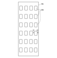
- Each punched area 32 of the sheet material 30 shown in FIG. 14 is formed as a plurality of circular hole openings 33 formed in two stages along the longitudinal direction (X-axis direction) of the sheet material 30.
- the plurality of circular hole openings 33 are formed in two stages along the longitudinal direction, but it is preferable that they are formed in multiple stages, such as three or more stages, along the longitudinal direction of the sheet material 30.
- the openings 33 on the upstream side (-X axis direction side) and the openings 33 on the downstream side (+X axis direction side) are the same in number and shape arranged in the width direction (Y axis direction).
- the multiple openings 33 on the upstream side (-X axis direction side) and the multiple openings 33 on the downstream side (+X axis direction side) are misaligned in the width direction (Y axis direction).
- the sheet material 30 may be formed in the punching section 66 (see FIG. 4) of the manufacturing apparatus 50 described above so as to form a plurality of circular hole openings 33.
- the sheet material 30 with the circular hole openings 33 pre-formed as shown in FIG. 14 may be wound around the bobbin 52a.
- the position, size, shape, etc. of the punched area 32 in the sheet material 30 are appropriately set according to the filter segment 20 for the flavor inhalation article 10 to be manufactured.
- a flavor suction article 10 and a rod segment (filter segment) 20 for the flavor suction article 10 in which areas with different performance (punched area 32 and holeless area 34) are formed from a single member (sheet material 30) and the amount of fluid filtration, etc. can be adjusted. Furthermore, according to this modified example, it is possible to provide a manufacturing device 50 capable of manufacturing such a rod segment (rod) 20 for the flavor suction article 10, and a manufacturing method for the rod segment (rod) 20 for the flavor suction article 10.
- the punched shape of the punching area 32 i.e., the shape of the opening 33
- the opening 33 does not have corners, it may be chamfered or rounded, or may be a circle, ellipse, or the like. In this case, when punching the sheet material 30, it is easy to punch and easy to remove by suction. If the opening 33 has corners, there is a possibility that the corners of the sheet material 30 and the punched piece of paper will remain connected when the sheet material 30 is punched out. However, by making the opening 33 chamfered or rounded rather than having corners, it is possible to prevent the punched piece of paper from remaining connected to the sheet material.
- Second Embodiment The second embodiment will be described with reference to Figures 15A and 15B.
- This embodiment is a modification of the first embodiment, and the same members or members having the same functions as those described in the first embodiment including each modification are denoted by the same reference numerals, and detailed description thereof will be omitted.
- FIG. 15A shows a schematic diagram of the flavor inhalation article 10 according to this embodiment.
- the structure of the filter segment 20 of the flavor inhalation article 10 is opposite to the upstream and downstream sides of the structure of the filter segment 20 of the flavor inhalation article 10 shown in FIG. 1.
- FIG. 15B shows the liquid addition unit 68a and the sheet material 30 in the manufacturing apparatus 50 according to this embodiment, viewed from above the liquid addition unit 68a and the sheet material 30.
- the liquid adding section 68a has, for example, a first nozzle 681.
- the multiple ejection portions of the first nozzle 681 continue to eject a first additive (e.g., a first liquid) L1 having an appropriate viscosity along a region R1 along the longitudinal direction of the sheet material 30, which includes the opening 33 punched by the punching portion 66 (see FIG. 4).
- a first additive e.g., a first liquid
- the first additive L1 preferably has the property of becoming liquid at a temperature higher than normal atmospheric temperature, for example 60°C or higher, and becoming more viscous or solidifying when ejected from the first nozzle 681 when the temperature drops to normal atmospheric temperature.
- the opening 33 of the region R1 is inserted in the Z-axis direction (vertical direction), so the first additive L1 does not adhere to the opening 33. Therefore, at least a part of the first additive L1 passes through the opening 33 of the punching region 32. That is, the first additive L1 does not adhere to the opening 33 of the punching region 32 according to this embodiment.
- the first additive L1 adheres to the opening edge of the opening 33 of the punching region 32, which is the boundary between the punching region 32 and the holeless region 34.
- the holeless region 34 between the adjacent openings 33 of the region R1 along the longitudinal direction of the sheet material 30 is closed in the Z-axis direction (vertical direction). Therefore, the first additive L1 adheres to the holeless region 34. Therefore, the first additive L1 is added to the holeless region 34. For this reason, in this embodiment, the first additive L1 adheres to the holeless region 34 and does not adhere to the punched region 32 along the longitudinal direction of the sheet material 30. Therefore, in one segment S (filter material 22) of the sheet material 30 shown in Figure 2, it is possible to form a region where the first additive L1 adheres (holeless region 34) and a region where the first additive L1 does not adhere (punched region 34).
- the method of adding the first additive L1 to the sheet material 30, which is part of the manufacturing method of the filter segment (rod segment) 20 in this embodiment, includes alternately supplying the first additive L1 to the punching region 32 and the holeless region 34 of the sheet material 30 conveyed along the conveying direction while fixing the injection position of the first additive L1.
- the first additive L1 By passing the first additive L1 through the opening 33 of the punching region 32, the position of the nozzle 681 is fixed, and the first additive L1 is simply continuously ejected from the nozzle 681, for example, downward, so that the first additive L1 is not attached to the opening 33 of the punching region 32, but is attached to the holeless region 34.
- the tip surface 14a side of the mouthpiece segment 14 can be formed as a holeless region 34 to which the first additive L1 is attached, and the rear surface (suction end) 14b side of the mouthpiece segment 14 can be formed as a punched region 32 to which the first additive L1 is not attached. Therefore, when a user holds the suction end 14b of the flavor inhalation article 10 in his mouth and inhales, he can appropriately feel the flavor of the first additive L1.
- a portion of the first additive L1 may be added to the blocked area between the openings 33, including the edges of the openings 33 formed at intervals in the width direction of the sheet material 30, in the punched area 32.
- the sheet material 30 containing the liquid added from the liquid adding section 68a is used as a paper filter, it is preferable to place a segment with less liquid on the downstream side to prevent leakage of the first additive (liquid) L1. Therefore, on the suction end 14b side of the filter segment 20, it is preferable to place a punched area 32 to which the first additive L1 does not adhere, downstream of the holeless area 34 to which the first additive L1 adheres.
- a liquid is used as the first additive L1
- the first additive L1 is preferably one that selectively exhibits filtering performance for specific components.
- sheet material 30 is made of paper
- a liquid that has phenol adsorption ability is preferable.
- paper filter material 22 for example, polyol, polypropylene glycol, polypropylene glycol glyceryl ether, polybutylene glycol, diglycerin, sorbitan fatty acid ester, glycerin fatty acid ester, polyglycerin fatty acid ester, propylene glycol fatty acid ester, polyethylene glycol, etc. are used.
- the liquid as the first additive L1 preferably has a relatively high viscosity.
- the viscosity of the liquid is preferably 1 cP to 20,000 cP, and more preferably 1,000 cP to 10,000 cP.
- a time lag occurs in the response of the first additive L1 to the on (open)/off (close) of the discharge portion of the nozzle 681. That is, even if the nozzle 681 is turned on (open), it takes time for the first additive L1 to flow onto the sheet material 30, and even if the nozzle 681 is turned off (closed), the liquid may flow onto the sheet material 30 for an appropriate period of time. For this reason, even if the sheet material 30 is transported at a constant speed, for example, it is difficult to create areas where the first additive L1 is to be added and areas where it is not to be added.
- the sheet material 30 when the sheet material 30 is moved along the longitudinal direction, and liquid is continuously ejected directly downward from the nozzle 681, the first additive L1 can be adhered to the holeless region 34 and the first additive L1 can be prevented from being adhered to the punched region 32 by passing through the opening 33. Therefore, the punched region 32 can be formed as a region where the first additive L1 is not added, and the holeless region 34 can be formed as a region where the first additive L1 is added. In this way, the manufacturer of the filter assembly 18 can adjust whether or not the first additive L1 is added to the punched region 32 and the holeless region 34.
- the amount of the first additive (liquid) L1 added per filter segment 20 is preferably, for example, 1 mg to 100 mg, and more preferably 5 mg to 50 mg.
- the liquid that passes through the opening 33 can be collected by a tray 683 (see Figure 4) directly below the nozzle 681 and reused, such as by being supplied to the nozzle 681 again.
- a flavor suction article 10 and a filter segment 20 for the flavor suction article 10 in which regions with different performances (punched region 32 and holeless region 34) are formed from a single member (sheet material 30) and the amount of fluid filtered can be adjusted.
- a manufacturing device 50 capable of manufacturing such a rod segment (rod) 20 for the flavor suction article 10, and a manufacturing method for the rod segment (rod) 20 for the flavor suction article 10.
- a rod segment 20 for the flavor suction article 10 in which regions with different amounts of additive L1 added (punched region 32 and holeless region 34) can be formed from a single member (sheet material 30), and a manufacturing method for the rod segment 20 for the flavor suction article 10.
- the first additive L1 can also be added to a nonwoven sheet material, a resin sheet material, or a tobacco sheet material, each of which has a punched region 32 and a holeless region 34. That is, the sheet material 30 applied to the first addition section 68a of the manufacturing device 50 is appropriately selected from paper, nonwoven, resin, tobacco sheet material, etc.
- the granule adding section 68b shown in FIG. 4 adds, for example, fragrance granules, activated carbon, microcapsules, and other granules to the sheet material 30.
- the granule adding section 68b has a travel guide 691 and a granule supply section 692 provided directly above the travel guide 691.
- the travel guide 691 transports the sheet material 30 at a predetermined speed, for example.
- the granule supply section 692 selectively adds granules to, for example, the punching area 32 and the holeless area 34.
- the activated carbon described above is added as the granules.
- the density of the activated carbon is set appropriately. Some of the activated carbon falls through, for example, openings 33 in the sheet material 30. The fallen activated carbon is collected in a tray or the like.
- Activated carbon is used to absorb moisture and tar, similar to so-called charcoal filters. It is preferable that the density of the activated carbon is greater in the holeless region 34 than in the punched region 32.
- the microcapsules are formed to have a smaller particle size than the capsules 38 (see FIG. 12) that are crushed by the user.
- a particle size of, for example, about 0.3 mm to 4 mm is preferable.
- the microcapsules contain a fragrance, and for example, the microcapsules melt gradually from the outside due to thermal conduction, allowing the fragrance to be released.
- the first additive L1 may adhere to the punched region 32, but the amount of adhesion can be suppressed compared to the holeless region 34. Therefore, it is preferable to place the punched region 32, where less first additive L1 adheres, on the suction end 14b side of the filter segment 20.
- granules can also be added to nonwoven sheet material, resin sheet material, and tobacco sheet material, each of which has a punched area 32 and a holeless area 34.
- the sheet material 30 applied to the second adding section 68b of the manufacturing device 50 is appropriately selected from paper, nonwoven sheet material, resin, tobacco sheet material, etc.
- the first additive L1 is added to the sheet material 30 after the openings 33 are formed in the sheet material 30 along the flow of the manufacturing apparatus 50.
- the first additive L1 may be added to the holeless sheet material 30 in the longitudinal direction, and then the openings 33 may be formed using the punching section 66 described above.
- This manufacturing method also results in the first additive L1 being added (attached) intermittently to the sheet material 30 in the longitudinal direction.
- FIG. 16 shows a top view of the sheet material 30.
- the liquid addition section 68a has, for example, a second nozzle 682 in addition to the first nozzle 681 described above.
- the second nozzle 682 continues to eject a second additive (e.g., a second liquid) L2 having an appropriate viscosity along a region R2 along the longitudinal direction, which includes the space between the openings 33 punched by the punching portion 66.
- a second additive e.g., a second liquid
- the second additive L2 preferably becomes liquid at a temperature higher than normal atmospheric temperature, for example, 60°C or higher, and has a property of becoming highly viscous or solidifying when discharged when the temperature drops to normal atmospheric temperature. It is preferable that the first additive (liquid) L1 has a higher viscosity than the second additive (liquid) L2. In this case, the first additive L1 attached to the edge of the opening 33 (the boundary between the punched area 32 and the holeless area 34) is unlikely to fall off from the opening 33. Therefore, even when the sheet material 30 is conveyed downstream, it is possible to prevent the first additive L1 from falling off and adhering to the manufacturing device 50 after the addition section 68.
- the second additive L2 It is also possible to prevent the second additive L2 from falling off and adhering to the manufacturing device 50 after the addition section 68. It is also preferable that the second additive L2 has a relatively low viscosity, and is likely to adhere only to the closed area of the sheet material 30. Therefore, the second additive L2 is prevented from falling off the sheet material 30 and adhering to the manufacturing device 50 after the addition section 68.
- the second additive L2 When the second additive L2 is continuously ejected from the second nozzle 682 while the sheet material 30 is being transported in the longitudinal direction, the second additive L2 is continuously adhered to the region R2 along the longitudinal direction of the region R2. In other words, the second additive L2 is continuously adhered to the sheet material 30 along the longitudinal direction.
- the method of adding the second additive L2 to the sheet material 30, which is part of the manufacturing method of the filter segment (rod segment) 20 in this modified example, includes alternately supplying the second additive L2 to the punching region 32 and the holeless region 34 of the sheet material 30 conveyed along the conveying direction while fixing the supply position of the second additive L2 relative to the supply position of the first additive L1.
- adding the second additive L2 to the sheet material 30 includes attaching the second additive L2 to both the region outside the opening 33 of the punching region 32 of the sheet material 30 conveyed along the conveying direction and the holeless region 34 while fixing the supply position of the second additive L2 relative to the supply position of the first additive L1.
- the second additive L2 can be attached between the openings 33 of the punching region 32 and the holeless region 34. Then, when the sheet material 30 to which the second additive L2 has been added is wound up as a filter segment (rod segment) 20 with a wrapper 24 (sheet-like member 24a) by the manufacturing device 50, a region containing the same additive L2 can be formed in the longitudinal direction of the filter segment (rod segment) 20.
- the filter segment 20 can be formed with an area to which the second additive L2 is attached, for example, from the tip surface 14a side to the rear end surface (suction end) 14b side of the mouthpiece segment 14. Therefore, when the user holds the suction end 14b of the flavor inhalation article 10 in his mouth and inhales, he can appropriately feel the flavor of the second additive L2. At this time, the opportunity for contact between the flavor generated in the flavor generation segment 12 and the flavor component from the second additive L2 can be increased.
- the liquid adding unit 68a may selectively eject the first additive L1 and the second additive L2 onto the sheet material 30 from the first nozzle 681 and the second nozzle 682. That is, the liquid adding unit 68a can eject the first additive L1 onto the sheet material 30 only from the first nozzle 681, or eject the second additive L2 onto the sheet material 30 only from the second nozzle 682 without ejecting the first additive L1 from the first nozzle 681.
- the first additive L1 and/or the second additive L2 can also be added to a nonwoven sheet material, a resin sheet material, or a tobacco sheet material, each of which has a punched region 32 and a holeless region 34. That is, the sheet material 30 applied to the first addition section 68a of the manufacturing apparatus 50 is appropriately selected from paper, nonwoven, resin, tobacco sheet material, etc.
- a flavor suction article 10 and a filter segment 20 for the flavor suction article 10 in which regions with different performances (punched region 32 and holeless region 34) are formed from a single member (sheet material 30) and the amount of fluid filtered can be adjusted. Also, according to this modified example, it is possible to provide a rod segment 20 for the flavor suction article 10 in which regions with different amounts of additive L1 added (punched region 32 and holeless region 34) can be formed from a single member (sheet material 30), and a manufacturing method for the rod segment 20 for the flavor suction article 10.
- the flavor generating segment 12 of this embodiment has a tip plug 42 and a flavor generating portion 44.
- the flavor generating section 44 of this embodiment is formed, for example, in the same manner as the flavor generating segment 12 described in the first embodiment.
- the tip plug 42 is provided upstream of the flavor generating section 44.
- the tip plug 42 is used, for example, to prevent the tobacco material from falling off.
- the tip plug 42 of this embodiment is formed in the same manner as the filter segment 20 described in the first embodiment. That is, the tip plug 42 has a cylindrical filter material 22 and a wrapper 24 that covers the outer periphery of the filter material 22. In the tip plug 42, the punched area 32 and the holeless area 34 are arranged adjacent to each other. The area including the tip surface 12a is formed in the punched area 32.
- the punched range of the sheet material 30 that forms the filter material 22 in this embodiment may be larger or smaller than the area of the opening 33 in the punched area 32 when used as the filter segment 20.
- liquid additives first additive L1, second additive L2
- granular additives may or may not be present.
- the area including the tip surface 12a of the tip plug 42 is formed in the punched area 32.
- the holeless area 34 and the flavor generating section 44 are connected.
- an aerosol source such as propylene glycol or glycerin is added to the tip plug 42 using nozzles 681, 682 shown in Figures 15A to 16.
- the mouthpiece segment 14 is provided on the rear end side of the flavor generating section 44.
- the mouthpiece segment 14 has a cooling segment 46 and a filter segment 48.
- the filter segment 48 in this embodiment may be the filter segment 20 described in the first embodiment, or may be a filter segment made of, for example, acetate tow in a rod shape, the outer circumference of which is wrapped with a wrapper 24.
- the mouthpiece segment 14 has a cooling segment 46 between the rear end surface 12b of the flavor generating segment 12 and the tip surface of the filter segment 20.
- the cooling segment 46 is located downstream of the flavor generating segment 12.
- the cooling segment 46 When the heated and vaporized aerosol base material or flavor source vapor is introduced into the cooling segment 46, it is cooled and condensed (aerosolized). It is preferable for the cooling segment 46 to cool the temperature without significantly removing the aerosol base material or flavor source vapor generated in the flavor generation segment 12. For example, during inhalation, the difference between the internal segment temperature at the inlet of the cooling segment 46 (near the rear end surface 12b of the flavor generation segment 12) and the internal segment temperature at the outlet of the cooling segment 46 (near the tip surface of the filter segment 20) may be 20°C or more.
- cooling segment 46 is a hollow member with an outside air inlet hole formed in a cylindrical paper tube. In another aspect, it is also preferable to fill the inside of the cylindrical paper tube with a cooling sheet material.
- the cooling sheet material used for the cooling segment 46 is preferably a sheet material that can be manufactured in a similar manner to the manufacturing of the filter segment 20 from the sheet material 30 described in the first embodiment. When the cooling segment 46 is manufactured using the manufacturing device 50, the above-mentioned addition section 68 may not be necessary.
- a low level of component filtration can be achieved while cooling is performed by providing one or more air flow channels in the flow direction of the cooling segment 46. It is desirable that the airflow resistance of the cooling segment 46 when filled with this cooling sheet material is 0 mmH2O /mm to 30 mmH2O /mm.
- the total surface area of the cooling sheet material may be 300 mm 2 /mm or more and 1000 mm 2 /mm or less. This surface area is the surface area per length (mm) of the cooling sheet material in the air passage direction.
- the total surface area of the cooling sheet material is preferably 400 mm 2 /mm or more, more preferably 450 mm 2 /mm or more, while it is preferably 600 mm 2 /mm or less, more preferably 550 mm 2 /mm or less.
- the cooling segments 46 may have a suitable amount of surface area for contacting the aerosol.
- the cooling sheet may be formed from a thin sheet of material that is wrinkled to form channels in the flow direction, and then pleated, gathered, and folded. The more folds or pleats within a given volume of the element, the greater the total surface area of the cooling sheet.
- the thickness of the cooling sheet material is 5 ⁇ m or more and 500 ⁇ m or less, for example, 10 ⁇ m or more and 250 ⁇ m or less.
- the cooling sheet material is preferably made of a material having a specific surface area of 10 mm 2 /mg or more and 100 mm 2 /mg or less. In one embodiment, the specific surface area of the constituent material may be about 35 mm 2 /mg.
- the specific surface area can be determined by considering the cooling sheet material having a known width and thickness.
- the cooling sheet material can be polylactic acid with an average thickness of 50 ⁇ m and a variation of ⁇ 2 ⁇ m. If the cooling sheet material also has a known width, for example between 200 mm and 250 mm, the specific surface area and density can be calculated.
- the paper as the cooling sheet material has a basis weight of 30 g/m 2 to 100 g/m 2 and a thickness of 20 ⁇ m to 100 ⁇ m.
- the air permeability of the paper as the cooling sheet material is preferably 10 Coresta units or less.
- the cooling effect can be increased by utilizing the heat of dissolution accompanying the heat absorption or phase change of the coating.
- a flavor suction article 10 and a filter segment 20 for the flavor suction article 10 in which regions with different performance (punched region 32 and holeless region 34) are formed from a single member (sheet material 30) and the amount of fluid filtration, etc. can be adjusted. Furthermore, according to this embodiment, it is possible to provide a manufacturing device 50 capable of manufacturing such a rod segment (rod) 20 for the flavor suction article 10, and a manufacturing method for the rod segment (rod) 20 for the flavor suction article 10.
- the manufacturing device 50 described in the first embodiment can be used to crepe the cooling sheet material to form it into a cylindrical rod, thereby forming the cooling segment (cooling rod segment) 46 of the mouthpiece segment 14.
- the manufacturing device 50 described in the first embodiment can roll up various sheet materials, not only for the filter segment 20, but also for the cooling segment 46 and flavor generating segment (tobacco sheet material) 12 described in this embodiment, together with the sheet-like member 24a that becomes the wrapper 24, to form cylindrical rod segments.
- a flavor inhalation article a flavor generating segment; a filter segment provided downstream of the flavor generating segment,
- the filter segment comprises: A filter material; a wrapper that wraps around the outside of the filter material to form the filter segment into a rod;
- the filter material is formed of a sheet material including a punched area that is partially punched and a holeless area that is not punched. Flavor-inhaling articles.
- Appendix 2 Along the axial direction of the rod, the punched region of the filter material of the filter segment is disposed upstream of the holeless region. Attachment 1, a flavor inhalation article.
- the filter segment has a mouth end formed at the holeless region of the filter material.
- the punched areas define a plurality of openings in the sheet material; The edges of the plurality of openings are each rounded.
- the wrapper has a basis weight of 30 gsm or more and 100 gsm or less.
- the sheet material is made of a paper material, a nonwoven fabric material, or a resin material.
- a filter segment for a flavor inhalation article comprising: A filter material; a wrapper that wraps around the outside of the filter material to form the filter segment into a rod; The filter material is a punched region that is partially punched; and a holeless area that is not punched out. Filter segments.
- the present invention is not limited to the above-mentioned embodiment, and can be modified in various ways without departing from the gist of the present invention.
- the embodiments may be combined as appropriate, and in that case, the combined effect can be obtained.
- the above-mentioned embodiment includes various inventions, and various inventions can be extracted by combinations selected from the multiple components disclosed. For example, if the problem can be solved and the effect can be obtained even if some components are deleted from all the components shown in the embodiment, the configuration from which the components are deleted can be extracted as an invention.
Landscapes
- Chemical & Material Sciences (AREA)
- Engineering & Computer Science (AREA)
- Materials Engineering (AREA)
- Cigarettes, Filters, And Manufacturing Of Filters (AREA)
- Perforating, Stamping-Out Or Severing By Means Other Than Cutting (AREA)
Priority Applications (5)
| Application Number | Priority Date | Filing Date | Title |
|---|---|---|---|
| CN202280102515.5A CN120282720A (zh) | 2022-12-19 | 2022-12-19 | 风味吸入制品以及用于风味吸入制品的过滤嘴段 |
| EP22969110.0A EP4640085A1 (en) | 2022-12-19 | 2022-12-19 | Flavor inhalation article, and filter segment for flavor inhalation article |
| JP2024565404A JPWO2024134721A1 (https=) | 2022-12-19 | 2022-12-19 | |
| PCT/JP2022/046671 WO2024134721A1 (ja) | 2022-12-19 | 2022-12-19 | 香味吸引物品、及び、香味吸引物品用のフィルタセグメント |
| KR1020257023064A KR20250122493A (ko) | 2022-12-19 | 2022-12-19 | 가향 흡입 물품 및 가향 흡입 물품용 필터 세그먼트 |
Applications Claiming Priority (1)
| Application Number | Priority Date | Filing Date | Title |
|---|---|---|---|
| PCT/JP2022/046671 WO2024134721A1 (ja) | 2022-12-19 | 2022-12-19 | 香味吸引物品、及び、香味吸引物品用のフィルタセグメント |
Publications (1)
| Publication Number | Publication Date |
|---|---|
| WO2024134721A1 true WO2024134721A1 (ja) | 2024-06-27 |
Family
ID=91588057
Family Applications (1)
| Application Number | Title | Priority Date | Filing Date |
|---|---|---|---|
| PCT/JP2022/046671 Ceased WO2024134721A1 (ja) | 2022-12-19 | 2022-12-19 | 香味吸引物品、及び、香味吸引物品用のフィルタセグメント |
Country Status (5)
| Country | Link |
|---|---|
| EP (1) | EP4640085A1 (https=) |
| JP (1) | JPWO2024134721A1 (https=) |
| KR (1) | KR20250122493A (https=) |
| CN (1) | CN120282720A (https=) |
| WO (1) | WO2024134721A1 (https=) |
Citations (5)
| Publication number | Priority date | Publication date | Assignee | Title |
|---|---|---|---|---|
| GB795534A (en) * | 1954-10-05 | 1958-05-28 | Olin Mathieson | Improvements in or relating to a method and apparatus for making a filter for tobacco smoke |
| JPH03103165A (ja) * | 1989-09-14 | 1991-04-30 | Sanjiyou Kikai Seisakusho:Kk | 紙製フイルターロッド製造装置 |
| JP2015515856A (ja) * | 2012-05-03 | 2015-06-04 | ブリティッシュ アメリカン タバコ (インヴェストメンツ) リミテッドBritish Americantobacco (Investments) Limited | 喫煙品フィルターの改良 |
| WO2019106625A1 (en) | 2017-12-03 | 2019-06-06 | Montrade S.P.A. | Device and method for the production of smoking article and the smoking article obtained |
| WO2021176524A1 (ja) * | 2020-03-02 | 2021-09-10 | 日本たばこ産業株式会社 | フィルタ、喫煙物品、及び、香味吸引物品 |
Family Cites Families (10)
| Publication number | Priority date | Publication date | Assignee | Title |
|---|---|---|---|---|
| DE341966C (https=) * | ||||
| US1967585A (en) * | 1933-04-12 | 1934-07-24 | Paul H Minton | Absorbent filter cartridge for smoking appliances |
| GB425869A (en) * | 1934-07-07 | 1935-03-22 | Muller J C & Co | Improvements in or relating to cigarettes |
| DE1082845B (de) * | 1953-08-04 | 1960-06-02 | Paul A Mueller | Filter fuer Tabakwaren, insbesondere Zigaretten |
| US2941533A (en) * | 1957-10-10 | 1960-06-21 | Charles P Crawford | Filter for cigarettes |
| US3640287A (en) * | 1969-09-22 | 1972-02-08 | Reynolds Tobacco Co R | Filter construction and method of forming same |
| US4047536A (en) * | 1974-06-19 | 1977-09-13 | Asfour Emil S | Method of making cigarettes and a cigarette made according thereto |
| US4100845A (en) * | 1975-05-15 | 1978-07-18 | Hauni-Werke Korber & Co. Kg | Method and machine for producing filter elements for tobacco smoke |
| CN109160355A (zh) * | 2018-10-31 | 2019-01-08 | 云南中烟工业有限责任公司 | 一种卷烟滤棒 |
| JP3227591U (ja) | 2020-06-02 | 2020-09-03 | 株式会社 東亜産業 | 喫煙具用のシート材、基材形成体、カートリッジ、及びシート材の製造装置 |
-
2022
- 2022-12-19 EP EP22969110.0A patent/EP4640085A1/en active Pending
- 2022-12-19 JP JP2024565404A patent/JPWO2024134721A1/ja active Pending
- 2022-12-19 CN CN202280102515.5A patent/CN120282720A/zh active Pending
- 2022-12-19 KR KR1020257023064A patent/KR20250122493A/ko active Pending
- 2022-12-19 WO PCT/JP2022/046671 patent/WO2024134721A1/ja not_active Ceased
Patent Citations (5)
| Publication number | Priority date | Publication date | Assignee | Title |
|---|---|---|---|---|
| GB795534A (en) * | 1954-10-05 | 1958-05-28 | Olin Mathieson | Improvements in or relating to a method and apparatus for making a filter for tobacco smoke |
| JPH03103165A (ja) * | 1989-09-14 | 1991-04-30 | Sanjiyou Kikai Seisakusho:Kk | 紙製フイルターロッド製造装置 |
| JP2015515856A (ja) * | 2012-05-03 | 2015-06-04 | ブリティッシュ アメリカン タバコ (インヴェストメンツ) リミテッドBritish Americantobacco (Investments) Limited | 喫煙品フィルターの改良 |
| WO2019106625A1 (en) | 2017-12-03 | 2019-06-06 | Montrade S.P.A. | Device and method for the production of smoking article and the smoking article obtained |
| WO2021176524A1 (ja) * | 2020-03-02 | 2021-09-10 | 日本たばこ産業株式会社 | フィルタ、喫煙物品、及び、香味吸引物品 |
Non-Patent Citations (1)
| Title |
|---|
| See also references of EP4640085A1 |
Also Published As
| Publication number | Publication date |
|---|---|
| CN120282720A (zh) | 2025-07-08 |
| JPWO2024134721A1 (https=) | 2024-06-27 |
| EP4640085A1 (en) | 2025-10-29 |
| KR20250122493A (ko) | 2025-08-13 |
Similar Documents
| Publication | Publication Date | Title |
|---|---|---|
| KR102157508B1 (ko) | 에어로졸 발생 물품에 사용하기 위한 풍미 로드 | |
| JP6860345B2 (ja) | 改良型ロッドを含む加熱式エアロゾル発生物品 | |
| RS54957B1 (sr) | Sistem za proizvodnju aerosola na električni pogon | |
| RS57517B1 (sr) | Štapići za upotrebu u proizvodima za pušenje | |
| RS54958B1 (sr) | Toplotnoprovodljivi štapići za upotrebu u proizvodima za stvaranje aerosola | |
| JP2015503344A (ja) | 喫煙品用フィルタアセンブリの方法 | |
| BRPI0709264A2 (pt) | artigo para fumar com um restritor | |
| CN102404999A (zh) | 用于将物体插入抽吸制品的过滤部分内的设备及相关方法 | |
| US20110180084A1 (en) | Apparatus and associated method for forming a filter component of a smoking article | |
| KR20150064731A (ko) | 마우스 말단의 오염이 감소된 흡연 물품 | |
| CA3043677A1 (en) | Filter element and method for manufacturing thereof | |
| US20240315318A1 (en) | Filling element used for flavor inhalation article and method for manufacturing filling element | |
| CN118354684A (zh) | 过滤器及具备该过滤器的香味吸取物品、以及该过滤器的制造装置及制造方法 | |
| CN117015315A (zh) | 用于输送系统的部件以及制造用于输送系统的部件的方法和设备 | |
| WO2024134721A1 (ja) | 香味吸引物品、及び、香味吸引物品用のフィルタセグメント | |
| WO2024134723A1 (ja) | 香味吸引物品用のロッドセグメント、及び、香味吸引物品用のロッドセグメントの製造方法 | |
| WO2024134722A1 (ja) | 香味吸引物品用のロッドの製造装置、及び、香味吸引物品用のロッドの製造方法 | |
| WO2025150159A1 (ja) | 香味生成物品用のロッド、香味生成物品、及び、香味生成物品用のロッドの製造方法 | |
| KR20240095453A (ko) | 향미 흡인 물품에 이용하는 충전 요소의 제조 장치 및 제조 방법 | |
| CN118354683A (zh) | 填充元件、填充元件的制造装置以及填充元件的制造方法 | |
| WO2026053438A1 (ja) | エアロゾル生成物品用セグメント、エアロゾル生成物品および非燃焼型エアロゾル生成システム | |
| KR20250097805A (ko) | 에어로졸 생성 물품 또는 흡연 물품용 요소 | |
| CN118354682A (zh) | 填充元件、填充元件的制造装置以及填充元件的制造方法 | |
| HK1203774B (en) | Flavoured rods for use in aerosol-generating articles |
Legal Events
| Date | Code | Title | Description |
|---|---|---|---|
| 121 | Ep: the epo has been informed by wipo that ep was designated in this application |
Ref document number: 22969110 Country of ref document: EP Kind code of ref document: A1 |
|
| WWE | Wipo information: entry into national phase |
Ref document number: CN2022801025155 Country of ref document: CN Ref document number: 202280102515.5 Country of ref document: CN |
|
| WWE | Wipo information: entry into national phase |
Ref document number: 2024565404 Country of ref document: JP |
|
| WWP | Wipo information: published in national office |
Ref document number: 202280102515.5 Country of ref document: CN |
|
| ENP | Entry into the national phase |
Ref document number: 1020257023064 Country of ref document: KR Free format text: ST27 STATUS EVENT CODE: A-0-1-A10-A15-NAP-PA0105 (AS PROVIDED BY THE NATIONAL OFFICE) |
|
| WWE | Wipo information: entry into national phase |
Ref document number: 1020257023064 Country of ref document: KR |
|
| WWE | Wipo information: entry into national phase |
Ref document number: 2022969110 Country of ref document: EP |
|
| NENP | Non-entry into the national phase |
Ref country code: DE |
|
| ENP | Entry into the national phase |
Ref document number: 2022969110 Country of ref document: EP Effective date: 20250721 |
|
| ENP | Entry into the national phase |
Ref document number: 2022969110 Country of ref document: EP Effective date: 20250721 |
|
| ENP | Entry into the national phase |
Ref document number: 2022969110 Country of ref document: EP Effective date: 20250721 |
|
| WWP | Wipo information: published in national office |
Ref document number: 1020257023064 Country of ref document: KR |
|
| WWP | Wipo information: published in national office |
Ref document number: 2022969110 Country of ref document: EP |