WO2024128296A1 - アンテナ装置 - Google Patents
アンテナ装置 Download PDFInfo
- Publication number
- WO2024128296A1 WO2024128296A1 PCT/JP2023/044935 JP2023044935W WO2024128296A1 WO 2024128296 A1 WO2024128296 A1 WO 2024128296A1 JP 2023044935 W JP2023044935 W JP 2023044935W WO 2024128296 A1 WO2024128296 A1 WO 2024128296A1
- Authority
- WO
- WIPO (PCT)
- Prior art keywords
- antenna device
- region
- protrusion
- metal base
- base
- Prior art date
- Legal status (The legal status is an assumption and is not a legal conclusion. Google has not performed a legal analysis and makes no representation as to the accuracy of the status listed.)
- Ceased
Links
Images









Classifications
-
- H—ELECTRICITY
- H01—ELECTRIC ELEMENTS
- H01Q—ANTENNAS, i.e. RADIO AERIALS
- H01Q1/00—Details of, or arrangements associated with, antennas
- H01Q1/12—Supports; Mounting means
- H01Q1/22—Supports; Mounting means by structural association with other equipment or articles
-
- H—ELECTRICITY
- H01—ELECTRIC ELEMENTS
- H01Q—ANTENNAS, i.e. RADIO AERIALS
- H01Q1/00—Details of, or arrangements associated with, antennas
- H01Q1/27—Adaptation for use in or on movable bodies
- H01Q1/32—Adaptation for use in or on road or rail vehicles
-
- H—ELECTRICITY
- H01—ELECTRIC ELEMENTS
- H01Q—ANTENNAS, i.e. RADIO AERIALS
- H01Q1/00—Details of, or arrangements associated with, antennas
- H01Q1/48—Earthing means; Earth screens; Counterpoises
Definitions
- the present invention relates to an antenna device.
- Patent document 1 discloses an antenna device that can be attached to a vehicle.
- the antenna device When an antenna device is attached to, for example, the roof of a vehicle, the antenna device may be affected by unwanted resonances that occur in the ground plate or metal base of the antenna device. In such cases, the capacitance between the ground plate or metal base and the roof may be changed to shift the frequency of the unwanted resonances so that the effect on the antenna device is reduced.
- One object of the present invention is to suppress the effects of unwanted resonance on an antenna device. Other objects of the present invention will become apparent from the description of this specification.
- One aspect of the present invention is an antenna device comprising a base that is attached to a metallic object, an antenna that is disposed on a first surface side of the base, and a first protrusion that extends from a second surface side of the base opposite the first surface toward the object, the base including a metallic member, the metallic member having a shape having a length and a width, and the first protrusion that is disposed shifted from a center line of the metallic member that extends in the direction of the length.
- the above aspect of the present invention makes it possible to suppress the effects of unwanted resonance occurring in the antenna device.
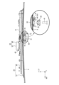
- FIG. 2 is a diagram showing a configuration of an antenna device 10A.
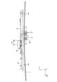
- FIG. 2 is a plan view of the inside of the antenna device 10A.
- 4 is a diagram for explaining the back surface of the metal base 30.
- FIG. 2 is a diagram for explaining a state in which the antenna device 10A is attached to a roof 2.
- FIG. 1A and 1B are diagrams showing radiation characteristics of a patch antenna 50 in an antenna device 10A.
- 2 is a diagram for explaining a state in which the antenna device 10A is attached to a roof 2.
- FIG. 11 is a diagram for explaining the parasitic capacitance between the metal base 30 and the roof 2.
- FIG. 11 is a diagram for explaining the parasitic capacitance between the metal base 32 and the roof 2.
- FIG. 1 is a diagram showing a configuration of an antenna device 10A.
- FIG. 2 is a plan view of the inside of the antenna device 10A.
- 4 is a diagram for explaining the back surface of the metal base 30.
- FIG. 2 is
- FIG. 11 is a diagram showing the radiation characteristics of a patch antenna 50 in an antenna device 10B.
- FIG. 11 is a diagram showing a voltage distribution on a metal base 30 in an antenna device 10A.
- FIG. 13 is a diagram showing a voltage distribution on a metal base 32 in an antenna device 10B.
- FIG. 12 is a schematic diagram for explaining voltage distribution in the A3-A3 cross section of FIG. 11.
- FIG. 1 is a diagram showing an example of voltage distribution in a typical microstrip antenna.
- FIG. 2 is a schematic diagram illustrating a configuration for suppressing unnecessary resonance.
- 4A to 4C are diagrams for explaining a leaf spring 210.
- 4 is a diagram for explaining the back surface of the metal base 30.
- FIG. 11 is a diagram showing a voltage distribution on a metal base 30 in an antenna device 10C.
- FIG. 13 is a diagram for explaining the rear surface of the metal base 30 on which the leaf springs 210a to 210d are arranged.
- FIG. 1 is a diagram showing a configuration of an antenna device 500.
- FIG. 13 is a diagram for explaining the back surface of a metal base 610.
- Fig. 1 is a side view of a vehicle 1 to which an antenna device 10A is attached. Fig. 1 also shows an enlarged view of the antenna device 10A attached to the vehicle. Here, the antenna device 10A is attached to a roof 2 of the vehicle 1. Note that the "vehicle” refers to a vehicle with wheels, such as an automobile or construction equipment.
- the front-to-rear direction of vehicle 1 is defined as the x direction
- the left-to-right direction perpendicular to the x direction is defined as the y direction
- the vertical direction perpendicular to the x and y directions is defined as the z direction.
- the front side is defined as the +x direction
- the right side is defined as the +y direction
- the zenith direction (upward) is defined as the +z direction.
- the front-to-rear, left-to-right, and up-to-down directions of antenna device 10A will be described as being the same as the front-to-rear, left-to-right, and up-to-down directions of vehicle 1.
- the antenna device 10A is an antenna device used in a vehicle (hereinafter, may be appropriately referred to as a "vehicle antenna device"), and is configured to include an antenna base 20, a case 21, substrates 40 to 42, and a patch antenna 50.
- the antenna base 20 is a plate-like member that forms the bottom surface of the antenna device 10A and is composed of a metal base 30 and a pad 31.
- the metal base 30 is a "metal member" that functions as the ground of the antenna device 10A by being electrically connected to the vehicle 1.
- the metal base 30 is, for example, a die-cast product made of an aluminum alloy.
- the pad 31 is a waterproofing member attached to the metal base 30 so as to surround the outer periphery of the metal base 30. As will be described in detail later, when the antenna device 10A is attached to the vehicle 1, the pad 31 adheres closely to the roof 2 so that there is no gap between the antenna device 10A and the roof 2. As a result, the pad 31 can prevent water from entering the inside of the antenna device 10A.
- the antenna base 20 is described here as being composed of the metal base 30 and the pad 31, this is not limited to this.
- the antenna base 20 may include a metal plate (i.e., a metal sheet) instead of the metal base 30.
- the antenna base 20 may also be composed of an insulating base made of resin and either a metal base or a metal plate. Furthermore, the antenna base 20 may be composed of three components: an insulating base, a metal base, and a metal plate. In such cases, the metal plate may correspond to the "metal member.”
- the case 21 is a member (so-called radome) that covers the antenna base 20 and, together with the antenna base 20, forms a storage space in which the patch antenna 50 and the like are stored.
- the case 21 is made of synthetic resin (e.g., ABS resin) that is electromagnetically transparent, and has a shark fin shape that is low at the front and increases in height toward the rear.
- Substrate 40 is a circuit board on which patch antenna 50, described later, is mounted, and is disposed on the front surface (upward surface) of metal base 30.
- Substrates 41 and 42 are also circuit boards on which antennas are mounted.
- the patch antenna 50 is an antenna for receiving radio waves, for example, in the L1 band (center frequency: 1575.42 MHz) and L5 band (center frequency: 1176.45 MHz) for the Global Navigation Satellite System (GNSS).
- the patch antenna 50 includes a dielectric 60 formed of a dielectric material such as ceramic, and a radiating element 61 that supports radio waves in the L1 and L5 bands.
- patch antenna 50 is mounted only on board 40 out of boards 40 to 42, but antennas may also be mounted on boards 41 and 42.
- board 41 may be mounted with an antenna compatible with telematics radio waves such as LTE (Long Term Evolution) or an antenna for receiving AM/FM radio radio waves.
- board 41 may be mounted with an antenna for receiving radio waves in the DAB (Digital Audio Broadcast) wave band.
- An LTE antenna is compatible with radio waves in the 700 MHz to 5.0 GHz band, for example.
- an antenna compatible with radio waves for V2X (Vehicle-to-Everything) or a keyless antenna for a keyless entry system may be mounted on the substrate 42.
- the keyless entry system is also called a smart entry system, and the operating frequency of the keyless antenna is, for example, 925 MHz.
- FIG. 2 shows only one patch antenna 50 for the sake of convenience, the antenna device 10A is a composite antenna device that can accommodate multiple antennas.
- the front surface (or upper surface) of the antenna base 20 corresponds to the "first surface”
- the back surface (or lower surface) of the antenna base 20 corresponds to the "second surface.”
- the direction of the front surface side of the antenna base 20 and the direction of the front surface side of the metal base 30 are both upward directions, and the direction of the back surface side of the antenna base 20 and the direction of the back surface side of the metal base 30 are both downward directions.
- Figure 3 is a diagram for explaining the front side of the antenna base 20
- Figure 4 is a diagram for explaining the back side of the metal base 30
- Figure 5 is a diagram for explaining the state in which the antenna device 10A is attached to the roof 2.
- FIG. 5 is a side view of antenna device 10A mounted on roof 2 as seen from the left, but for convenience, only roof 2 is shown as a cross section taken along line A1-A1 in FIG. 3.
- metal base 30 has a shape with a length extending in the front-to-rear direction and a width extending in the left-to-right direction when viewed from above.
- the front-to-rear direction may be referred to as the "longitudinal direction (or longitudinal direction)" and the left-to-right direction may be referred to as the “width direction (or width direction).”
- the center line extending in the longitudinal direction of metal base 30 is referred to as the "center line CL.”
- a resin member 70 is fitted into the opening 35 near the center of the metal base 30 (see the enlarged view in Figure 4) from the front side of the metal base 30. Also, as shown in Figure 3, a recess 71 and an opening 72 are formed in the member 70. For convenience, the enlarged view in Figure 4 shows only the opening 35 and the mounting portion 36 (described below) formed in the metal base 30, and omits the member 70, etc.
- the recess 71 is, for example, a recess for determining the position of the power supply line (not shown) of the patch antenna 50, and the power supply line is fitted into the recess 71.
- the opening 72 is a through hole formed in the member 70 for leading the power supply line from the front surface side of the metal base 30 to the back surface side.
- the back side of the metal base 30 is formed with an attachment portion 36 that is used when attaching the metal base 30 to the roof 2.
- the enlarged view of FIG. 5 shows the capture fastener 80 and the bolt 81 (described below) in disassembled state.
- the mounting portion 36 is a protrusion that extends downward from the back surface of the metal base 30 and is inserted into a through hole provided in the roof 2 of the vehicle 1.
- a metal capture fastener 80 for fixing the metal base 30 to the roof 2 is attached to the mounting portion 36.
- the capture fastener 80 After the capture fastener 80 is attached to the mounting portion 36, a bolt 81 is inserted into a screw hole (not shown) formed at the lower end of the mounting portion 36. As a result, a portion of the metal capture fastener 80 is fixed in contact with the rear surface (lower surface) of the roof 2, and the metal base 30 and roof 2 are electrically connected. Therefore, in the antenna device 10A, the metal base 30 functions as a ground.
- the pad 31 adheres closely to the front surface (top surface) of the roof 2 so that there is no gap between the pad 31 and the roof 2. This prevents water from entering the inside of the vehicle 1 through the gap between the antenna device 10A and the roof 2.
- Fig. 6 is a diagram showing the radiation efficiency of the patch antenna 50 in the antenna device 10A. Note that the horizontal axis of Fig. 6 represents the operating frequency of the patch antenna 50, and the vertical axis represents the radiation efficiency of the patch antenna 50.
- the antenna device 10A is attached to a metal plate (not shown) having a shape similar to that of the roof 2, and the radiation efficiency of the patch antenna 50 is measured. Note that hereinafter, the metal plate having a shape similar to that of the roof 2 is referred to as "metal plate X.”
- the patch antenna 50 when the patch antenna 50 is operated at 1700 MHz, the radiation efficiency of the patch antenna 50 deteriorates to -1.29 dB.
- the patch antenna 50 is an antenna compatible with the L1 band of the GNSS. Therefore, when the antenna device 10A is actually installed in a vehicle 1, it is expected that the reception characteristics of radio waves in the L1 band of the GNSS will deteriorate. Here, the cause of the deterioration in the radiation efficiency of the patch antenna 50 will be explained.
- Fig. 7 is a side view for explaining the mounting state of the antenna device 10A on the roof 2, similar to Fig. 5, but omitting the pad 31.
- a gap 100 is formed between the back surface of the metal base 30 and the front surface of the roof 2, as shown in Fig. 6.
- parasitic capacitance C0 a parasitic capacitance (hereinafter referred to as "parasitic capacitance C0") is generated between the metal base 30 and the roof 2, as shown in Fig. 8.
- the distance between the metal base 30 and the roof 2 in the A2-A2 cross section is designated as "distance d0".
- a voltage at a resonant frequency corresponding to the parasitic capacitance C0 and the inductance of the metal base 30 may generally be generated in the metal base 30. If the radiation characteristics of the patch antenna 50 are deteriorated due to unwanted resonance corresponding to the parasitic capacitance C0 and the inductance of the metal base 30, changing the parasitic capacitance C0 will also change the frequency at which the radiation characteristics deteriorate.
- a recess 110 (so-called "counterbore") recessed from the outer periphery of the metal base 32 is formed in the front part of the rear surface of the metal base 32.
- the metal base 30 and the metal base 32 have the same shape except for the recess 110.
- the distance d1 between the surface of the metal base 32 on which the recess 110 is formed and the front surface of the roof 2 is longer than the distance d0 shown in FIG. 8 described above.
- the parasitic capacitance C1 generated between the metal base 32 and the roof 2 is smaller than the parasitic capacitance C0 in FIG. 8, so it is expected that the resonant frequency caused by the parasitic capacitance C1 (i.e., the frequency of unwanted resonance) will be higher.
- the antenna device 10B is a vehicle antenna device that uses a metal base 32 instead of the metal base 30 (see FIG. 2).
- the configuration of the antenna device 10B is the same as that of the antenna device 10A except for the metal base 32. Therefore, a detailed description of the antenna device 10B will be omitted here.
- the antenna device 10B was attached to a metal plate X having the same shape as the roof 2, and the radiation efficiency of the patch antenna 50 in the antenna device 10B was measured.
- Figure 10 is a diagram showing the radiation efficiency (solid line) of the patch antenna 50 of the antenna device 10B.
- the radiation efficiency of the patch antenna 50 of the antenna device 10A is also shown by a dotted line.
- the radiation efficiency of the patch antenna 50 deteriorates to -1.83 dB.
- the frequency fb (1550 MHz) of the unwanted resonance in the antenna device 10B is lower than the frequency fa (1700 MHz) of the unwanted resonance in the antenna device 10A.
- the frequency fb will be higher than the frequency fa.
- the frequency fb is lower than the frequency fa, so it is believed that the unwanted resonances of the antenna devices 10A and 10B occur based on a physical phenomenon that is not caused by the parasitic capacitances C0 and C1.
- 11 is a diagram (simulation result) showing the voltage distribution on the back surface of the metal base 30 of the antenna device 10A.
- the color of the area where the voltage amplitude is large is displayed lighter.
- the voltage amplitude is large in the front and rightmost area 120a and the front and leftmost area 120b.
- Figure 12 shows the voltage distribution on the back surface of metal base 32 in antenna device 10B.
- areas with large voltage amplitude are shown in a lighter color.
- the voltage amplitude is also large in region 121a at the front and right edge, and region 121b at the front and left edge. In this way, in both metal bases 30 and 32, the voltage amplitude is large at the front and widthwise ends. For this reason, below, metal base 30 will be used to verify the physical phenomenon that causes unwanted resonance.
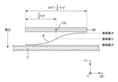
- FIG. 13 is a schematic diagram for explaining the voltage distribution in the A3-A3 cross section of the metal base 30 in FIG. 11.
- the voltage amplitude is minimum at the center (center line CL) of the metal base 30 in the width direction.
- the voltage amplitude increases as it moves away from the center line CL of the metal base 30 to the outside in the width direction, and is maximum at the outer edge of the metal base 30.
- the voltage amplitude is nearly zero (minimum value) at the center of the metal base 30, the voltage amplitude is the maximum positive value at the outer edge on the left side, and the voltage amplitude is the maximum negative value at the outer edge on the right side.
- standing wave S a standing wave with a widthwise length Lw of half the wavelength is generated in the metal base 30.
- the widthwise length Lw is a representative widthwise length (e.g., the length of the portion where the line A3-A3 cross section is drawn) in the area where the voltage amplitude is large and the standing wave S is generated (e.g., areas 120a and 120b in FIG. 11).
- the wavelength ⁇ s of the standing wave S is defined as the widthwise length of the portion where the A3-A3 cross section line shown in FIG. 11 is drawn, but this is not limited to this and it may be the widthwise length of the regions 120a, 120b where the standing wave in the widthwise direction occurs.
- FIG. 14 is a schematic diagram of a microstrip antenna viewed from the side so that the relationship between the radiating element and the ground plate can be seen.
- the radiating element of length L1 and width W1 (not shown) in Figure 14 corresponds to a part of the metal base 30, and the ground plate corresponds to the roof 2.
- Figure 14 shows the voltage distribution (solid line) and current distribution (dotted line) in the direction along the length L1 of the radiating element.
- the voltage amplitude is maximum at the left end and right end of the longitudinal length L1 of the radiating element. Specifically, the voltage amplitude is nearly zero (minimum value) at the center of the radiating element in the longitudinal direction of length L1, the voltage amplitude is the maximum positive value at the left end (outer edge portion), and the voltage amplitude is the maximum negative value at the right end.
- the unwanted resonance occurring in the metal base 30 of the antenna device 10A occurs because the metal base 30 and the roof 2 form a microstrip antenna with both ends open.
- 15 is a schematic diagram showing a configuration for suppressing unwanted resonance occurring in the metal base 30 (i.e., standing waves S occurring in the width direction of the metal base 30).
- the voltage amplitude of the standing waves S is maximum at the outer edge in the width direction where the impedance is high. Therefore, in order to suppress the standing waves S, it is sufficient to reduce the impedance in the area of the metal base 30 where the voltage amplitude of the standing waves S is large.
- a protrusion 200 that extends from the rear surface of the metal base 30 toward the roof 2 and contacts the front surface of the roof 2 may be disposed on the rear surface of the metal base 30.
- the "protrusion 200" can be, for example, a leaf spring 210 as shown in FIG. 16.
- FIG. 16 is a diagram for explaining the leaf spring 210, and includes a perspective view of the leaf spring 210 and a diagram showing the leaf spring 210 in use.
- the leaf spring 210 is composed of a fixed portion 220, an extending portion 221, and a bent portion 222.
- the fixed portion 220 is a portion that is fixed to the back surface of the metal base 30, for example, by conductive double-sided tape.
- the extending portion 221 extends diagonally downward from the end of the fixed portion 220, and the bent portion 222 is formed by bending the end of the extending portion 221 on the opposite side to the fixed portion 220. Then, when the metal base 30 is attached to the roof 2, part of the bent portion 222 is pressed against the roof 2.
- the leaf spring 210 has been described as an example of the "protrusion 200," but this is not limiting and any member capable of reducing the impedance between the metal base 30 and the roof 2 may be used.
- a portion of the back surface of the metal base 30 may be machined into a protrusion to form the protrusion 200.
- a conductive gasket may be used instead of the leaf spring 210.
- the protrusion 200 is in contact with the roof 2, but since it is sufficient to reduce the impedance between the metal base 30 and the roof 2, the protrusion 200 does not necessarily have to be in contact with the roof 2.
- the protrusion 200 is preferably positioned, for example, at a position shifted from the central axis CL by 1/4 ⁇ Lw (i.e., 1/8 ⁇ s) or more in the width direction. Note that, while FIG. 15 illustrates an example in which the protrusion 200 is positioned at a position shifted from the central axis CL by 1/8 ⁇ s or more, this is not limiting. By shifting the protrusion 200 in the width direction from the central axis CL, the amplitude of the standing wave S can be suppressed.
- the antenna device 10C is a vehicle antenna device similar to the antenna device 10A.
- the antenna device 10C has the same configuration as the antenna device 10A, except that a protrusion 200 is arranged on the rear surface side of the metal base 30. Therefore, here, the protrusion 200 arranged on the rear surface of the metal base 30 will be described.
- a leaf spring 210 is used as the protrusion 200, but as described above, other configurations (e.g., a gasket) may be used.
- the mounting portion 36 On the back surface of the metal base 30, the mounting portion 36 is disposed, and the area surrounded by the solid-line rectangle in FIG. 17 (the area of the mounting portion 36) is referred to as the "central region 300."
- the area that overlaps with the dashed-line rectangle drawn to the outside of the central region 300 to the right is referred to as the "outer region 310a”
- the area that overlaps with the dashed-line rectangle drawn to the outside of the central region 300 to the left is referred to as the "outer region 310b.”
- the outer regions 310a and 310b are regions that are located outside the central region 300 in the width direction and extend along the longitudinal direction.
- the outer region 310a in this embodiment includes adjacent region 320a, and regions 321a and 322a.
- Adjacent region 320a is a region of outer region 310a adjacent to central region 300.
- Region 321a is a region of outer region 310a located on the edge 37 side from adjacent region 320a
- region 322a is a region of outer region 310a located on the edge 38 side from adjacent region 320a.
- outer region 310b also includes adjacent region 320b, and regions 321b and 322b.
- Adjacent region 320b is a region of outer region 310b adjacent to central region 300.
- Region 321b is a region of outer region 310b located on the edge 37 side from adjacent region 320b
- region 322b is a region of outer region 310b located on the edge 38 side from adjacent region 320b.
- leaf spring 210a is arranged in the region 321a, and the leaf spring 210b is arranged in the region 321b, as shown in Fig. 17.
- the leaf springs 210a and 210b have the same configuration as the leaf spring 210 in Fig. 16 described above.
- FIG. 17 also illustrates the distance da from the center line CL to leaf spring 210a, and the distance db from the center line CL to leaf spring 210b.
- distance da is, for example, the distance from center line CL to the geometric center of leaf spring 210a in a planar view
- distance db is, for example, the distance from center line CL to the geometric center of leaf spring 210b in a planar view.
- the distances da and db in this embodiment are longer than the above-mentioned 1/4 ⁇ Lw (i.e., 1/8 ⁇ s).
- Fig. 18 is a diagram showing the radiation characteristics of the patch antenna 50 in the antenna device 10C.
- the radiation characteristics of the patch antenna 50 in the antenna device 10C are shown by a solid line, and the radiation characteristics of the patch antenna 50 in the antenna device 10A obtained in Fig. 6 are shown by a dotted line.
- the deterioration of the radiation characteristics of the patch antenna 50 in the antenna device 10A has been improved.
- Fig. 19 is a diagram showing the voltage distribution in the metal base 30 of Fig. 17 in which the leaf springs 210a and 210b are arranged. As is clear from comparing Fig. 19 with the voltage distribution in the metal base 30 in which the leaf springs are not arranged (see Fig. 11), unwanted resonance is suppressed and the voltage amplitude is reduced across the entire metal base 30.
- the leaf spring 210a and the leaf spring 210b are arranged symmetrically with respect to the center line CL, but this is not limited thereto.
- the distance da to the leaf spring 210a may be longer than the distance db to the leaf spring 210b.
- the leaf spring 210a may be arranged closer to the tip end 37 side than the leaf spring 210b.
- leaf spring 210a is arranged so that the longitudinal axis of leaf spring 210a is approximately parallel to the longitudinal center line CL of metal base 30, but this is not limited to this.
- the longitudinal axis of leaf spring 210a and the center axis CL may be approximately perpendicular, or may have a predetermined angle (e.g., 30°). Note that while the leaf spring 210a has been described here, the same applies to leaf spring 210b.
- the leaf springs 210a and 210b are arranged in regions 321a and 321b, respectively, which are symmetrical with respect to the center line CL, the voltage amplitude of the standing wave S can be made very small, and unwanted resonance can be suppressed.
- the leaf springs 210a and 210b may be arranged in the adjacent regions 320a and 320b, or in the regions 322a and 322b, which are symmetrical with respect to the center line CL. Even in such a case, the impedance between the metal base 30 and the roof 2 can be reduced, thereby suppressing unwanted resonance.
- two leaf springs 210a, 210b are arranged on the back surface of the metal base 30, but the number of leaf springs arranged is not limited to this.
- a gap may be formed between the roof and only one of the outer regions 310a, 310b, the outer region 310a. In such a case, by arranging one leaf spring only in the outer region 310a, it is possible to suppress unnecessary resonance caused by the gap between the metal base 30 and the roof.
- leaf spring is placed in the outer region 310a here, multiple leaf springs may be placed in the outer region 310a. In other words, by placing at least one leaf spring in the outer region 310a, unwanted resonance can be suppressed.
- the predicted gap may change depending on, for example, the precision with which the antenna device 10C is mounted.
- leaf springs 210a and 210b may be arranged in regions 321a and 321b, respectively, and leaf springs 210c and 210d may be arranged in regions 322a and 322b, respectively. Note that leaf springs 210c and 210d are arranged symmetrically with respect to center line CL.
- the voltage amplitude of the standing wave S can be reduced regardless of which area of the metal base 30 the standing wave S occurs in. Therefore, by arranging four leaf springs 210a to 210d on the metal base 30 as shown in Figure 20, unwanted resonance can be reliably suppressed.
- leaf spring 210a corresponds to the "first protrusion”
- leaf spring 210b corresponds to the “second protrusion”
- leaf spring 210c corresponds to the "third protrusion”
- leaf spring 210d corresponds to the "fourth protrusion.”
- the roof 2 of the vehicle 1 corresponds to the "metallic object.”
- each of the distances da to dd is longer than the above-mentioned 1/4 x Lw (i.e., 1/8 x ⁇ s).
- the antenna device 10C of this embodiment is intended to be used in a "vehicle,” which is a vehicle with wheels, but is not limited to this and may be used in, for example, flying objects such as drones, probes, construction machinery without wheels, agricultural machinery, ships, and other moving objects. Also, while the antenna device 10C is attached to the roof 2 of the vehicle 1, it may also be brought into the vehicle and attached, for example, to a metal part inside the vehicle.
- the antenna device 10C can suppress unwanted resonance that may occur when the antenna device 10C is attached to a metal part.
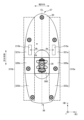
- the antenna device 500 in FIG. 21 is a device similar to the antenna device 10A in FIG. 2, and includes an antenna base 600, a case 601, a substrate 602, and a patch antenna 603.
- the antenna base 600 is a plate-like member that forms the bottom surface of the antenna device 500, and is composed of a metal base 610, a metal plate 611, and a pad 612. Note that the metal base 610 and the pad 612 are similar to the metal base 30 and the pad 31 of the antenna device 10A, respectively.
- the metal plate 611 is electrically connected to the metal base 610 and, together with the metal base 610, constitutes a "metal member.”
- the case 601 is a member that covers the antenna base 600 and forms a storage space in which the antenna base 600 and the patch antenna 603, etc. are stored.
- the substrate 602 is a circuit board on which the patch antenna 603 described below is mounted, and is disposed on the front surface of the metal base 610.
- patch antenna 603 is an antenna that supports radio waves in the L1 and L5 bands for GNSS.
- Patch antenna 603 includes a radiating element 700, holding members 701 and 702, and metal bodies 710 and 711, which are arranged on the front surface of a dielectric body (not shown).
- the metal body 710 is held by the holding member 701
- the metal body 711 is held by the holding member 702, so that the metal bodies 710 and 711 are positioned above the radiating element 700 in a surrounding shape that surrounds the center (geometric center) of the radiating element 700.
- metal bodies 710 and 711 are provided above the radiating element 700, which is the wave source, so the axial ratio of the patch antenna 603 can be adjusted.
- the metal bodies 710 and 711 have a surrounding shape that surrounds the center of the radiating element 700, changes in impedance of the patch antenna 603 can be suppressed.
- the front end of the antenna base 600 is referred to as end 650, and the rear end is referred to as end 651.
- a mounting portion 740 used when mounting the antenna base 600 to the roof 2 is disposed on the center line CL.
- the mounting portion 740 is similar to the mounting portion 36.
- the mounting portion 740 is disposed, and the area surrounded by the solid line rectangle in FIG. 17 (the area of the mounting portion 740) is referred to as the "central region 800."
- the area that overlaps with the dashed line rectangle drawn to the outside of the central region 800 to the right is referred to as the "outer region 810a”
- the area that overlaps with the dashed line rectangle drawn to the outside of the central region 800 to the left is referred to as the "outer region 810b.”
- the outer regions 810a and 810b are regions that are located outside the central region 800 in the width direction and extend along the longitudinal direction.
- the outer region 810a in this embodiment includes an adjacent region 820a, and regions 821a and 822a.
- the adjacent region 820a is a region of the outer region 810a that is adjacent to the central region 800.
- the region 821a is a region of the outer region 810a that is located on the end 650 side from the adjacent region 820a
- the region 822a is a region of the outer region 810a that is located on the end 651 side from the adjacent region 820a.
- outer region 810b also includes adjacent region 820b, and regions 821b and 822b.
- Adjacent region 820b is a region of outer region 810b adjacent to central region 800.
- Region 821b is a region of outer region 810b located on the edge 650 side from adjacent region 820b
- region 822b is a region of outer region 810b located on the edge 651 side from adjacent region 820b.
- leaf springs 750a and 750b are arranged in regions 821a and 821b, respectively, and leaf springs 750c and 750d are arranged in regions 822a and 822b, respectively.
- leaf springs 750a and 750b and leaf springs 750c and 750d are arranged symmetrically with respect to center line CL. Note that each of leaf springs 750a to 750d is similar to leaf spring 210a, etc.
- each of the distances da to dd is longer than the above-mentioned 1/4 ⁇ Lw (i.e., 1/8 ⁇ s).
- the voltage amplitude of the standing wave S can be reduced regardless of which area of the metal base 610 the standing wave S occurs in. Therefore, by arranging four leaf springs 750a to 750d on the metal base 610 as shown in Figure 22, unwanted resonance can be reliably suppressed.
- leaf spring 750a corresponds to the "first protrusion”
- leaf spring 750b corresponds to the “second protrusion”
- leaf spring 750c corresponds to the “third protrusion”
- leaf spring 750d corresponds to the "fourth protrusion.”
- an antenna device having the following aspects.
- Aspect 1 is an antenna device comprising: a base to be attached to a metallic object; an antenna arranged on a first surface side of the base; and a first protrusion extending from a second surface side opposite the first surface of the base toward the object, wherein the base includes a metal member, the metal member has a shape having a length and a width, and the first protrusion is arranged shifted from a center line of the metal member extending in the length direction.
- the leaf spring 210a which is shifted from the center line CL, can reduce the impedance between the metal base 30 and the roof 2, thereby suppressing unnecessary resonance.
- Aspect 2 is an antenna device further comprising an attachment portion used when attaching the base to the target object, the attachment portion being arranged on the center line of the second surface side of the base, the region of the attachment portion located on the center line being a central region, and the first protrusion portion being located outside the central region on the second surface of the base in the width direction and arranged in an outer region extending along the longitudinal direction.
- the leaf spring 210a is disposed in the outer region 310a of the metal base 30, so that the amplitude of the standing wave S of the metal base 30 can be reduced. As a result, unwanted resonance occurring in the metal base 30 is suppressed.
- Aspect 3 is an antenna device further comprising a second protrusion extending from the second surface side of the base toward the object, the second protrusion being positioned in the outer region.
- the leaf spring 210a is arranged in the outer region 310a
- the leaf spring 210b is arranged in the outer region 310b
- the two leaf springs 210a, 210b may be arranged in one of the two outer regions 310a, 310b (e.g., the outer region 310a). According to such an embodiment, the number of leaf springs arranged on the metal base 30 increases, so that the impedance between the metal base 30 and the roof 2 can be reduced more significantly.
- Aspect 4 is the antenna device, wherein the first protrusion and the second protrusion are arranged to sandwich the center line.
- leaf spring 210a and leaf spring 210b are arranged so as to sandwich center line CL.
- This embodiment can reduce the amplitude of standing wave S of metal base 30, thereby suppressing unwanted resonance.
- Aspect 5 is an antenna device in which the base has a first end in the longitudinal direction and a second end located opposite the first end, the outer region has an adjacent region adjacent to the central region in the width direction, a first region located on the first end side of the adjacent region, and a second region located on the second end side of the adjacent region, and the first protrusion and the second protrusion are arranged in the first region.
- leaf spring 210a is disposed in region 321a
- leaf spring 210b is disposed in region 321b.
- leaf spring 210a and leaf spring 210b are disposed in a region on the end 37 side of metal base 30, with center line CL between them. According to this embodiment, the amplitude of standing wave S of metal base 30 can be made smaller, thereby suppressing unwanted resonance.
- Aspect 6 is an antenna device further comprising a third protrusion and a fourth protrusion extending from the second surface side of the base toward the object, the third protrusion and the fourth protrusion being arranged in the second region so as to sandwich the center line between each other.
- leaf spring 210a is arranged in region 321a, and leaf spring 210b is arranged in region 321b. Furthermore, leaf spring 210c is arranged in region 322a, and leaf spring 210d is arranged in region 322b. According to this embodiment, regardless of the region in which standing wave S occurs on metal base 30, the amplitude of standing wave S can be reduced, thereby suppressing unwanted resonance.
- Aspect 7 is an antenna device in which the first protrusion and the second protrusion are arranged symmetrically with respect to the center line, and the third protrusion and the fourth protrusion are arranged symmetrically with respect to the center line.
- the distances da and db from the center line CL of the leaf springs 210a and 210b are equal, and the distances dc and dd from the center line CL of the leaf springs 210c and 210d are equal. Therefore, the amplitude of the standing wave S can be reliably reduced, thereby suppressing unwanted resonance.
- Aspect 8 is an antenna device, wherein the first protrusion is positioned so as to be shifted from the center line by 1 ⁇ 8 or more of the wavelength of a standing wave generated in the width direction of the metal member.
- the amplitude of the standing wave S generated in the metal base 30 can be reduced, thereby suppressing unwanted resonance.
- the object is a roof of a vehicle, in the antenna device.
- the above-described embodiment makes it possible to prevent unwanted resonance from occurring in the antenna device 10C when the antenna device 10C is attached to the roof 2 of the vehicle 1.
Landscapes
- Details Of Aerials (AREA)
- Support Of Aerials (AREA)
Priority Applications (2)
| Application Number | Priority Date | Filing Date | Title |
|---|---|---|---|
| JP2024564435A JPWO2024128296A1 (https=) | 2022-12-16 | 2023-12-14 | |
| CN202380079186.1A CN120226209A (zh) | 2022-12-16 | 2023-12-14 | 天线装置 |
Applications Claiming Priority (2)
| Application Number | Priority Date | Filing Date | Title |
|---|---|---|---|
| JP2022-201303 | 2022-12-16 | ||
| JP2022201303 | 2022-12-16 |
Publications (1)
| Publication Number | Publication Date |
|---|---|
| WO2024128296A1 true WO2024128296A1 (ja) | 2024-06-20 |
Family
ID=91485917
Family Applications (1)
| Application Number | Title | Priority Date | Filing Date |
|---|---|---|---|
| PCT/JP2023/044935 Ceased WO2024128296A1 (ja) | 2022-12-16 | 2023-12-14 | アンテナ装置 |
Country Status (3)
| Country | Link |
|---|---|
| JP (1) | JPWO2024128296A1 (https=) |
| CN (1) | CN120226209A (https=) |
| WO (1) | WO2024128296A1 (https=) |
Citations (4)
| Publication number | Priority date | Publication date | Assignee | Title |
|---|---|---|---|---|
| JP2013110601A (ja) * | 2011-11-21 | 2013-06-06 | Furukawa Electric Co Ltd:The | 車載用アンテナ装置 |
| JP2015084575A (ja) * | 2014-12-22 | 2015-04-30 | 原田工業株式会社 | アンテナ装置 |
| WO2017141635A1 (ja) * | 2016-02-19 | 2017-08-24 | 株式会社ヨコオ | アンテナ装置 |
| WO2019124518A1 (ja) * | 2017-12-20 | 2019-06-27 | 株式会社ヨコオ | 車載用アンテナ装置 |
-
2023
- 2023-12-14 JP JP2024564435A patent/JPWO2024128296A1/ja active Pending
- 2023-12-14 WO PCT/JP2023/044935 patent/WO2024128296A1/ja not_active Ceased
- 2023-12-14 CN CN202380079186.1A patent/CN120226209A/zh active Pending
Patent Citations (4)
| Publication number | Priority date | Publication date | Assignee | Title |
|---|---|---|---|---|
| JP2013110601A (ja) * | 2011-11-21 | 2013-06-06 | Furukawa Electric Co Ltd:The | 車載用アンテナ装置 |
| JP2015084575A (ja) * | 2014-12-22 | 2015-04-30 | 原田工業株式会社 | アンテナ装置 |
| WO2017141635A1 (ja) * | 2016-02-19 | 2017-08-24 | 株式会社ヨコオ | アンテナ装置 |
| WO2019124518A1 (ja) * | 2017-12-20 | 2019-06-27 | 株式会社ヨコオ | 車載用アンテナ装置 |
Also Published As
| Publication number | Publication date |
|---|---|
| JPWO2024128296A1 (https=) | 2024-06-20 |
| CN120226209A (zh) | 2025-06-27 |
Similar Documents
| Publication | Publication Date | Title |
|---|---|---|
| US11509053B2 (en) | Dual broadband antenna system for vehicles | |
| JP2025133836A (ja) | アンテナ装置 | |
| US20200274256A1 (en) | Ultra compact ultra broad band dual polarized base station antenna | |
| JP6195935B2 (ja) | アンテナ要素、アンテナ要素を有する放射器、二重偏波電流ループ放射器およびフェーズドアレイアンテナ | |
| US8508421B2 (en) | Hardened wave-guide antenna | |
| JP2018121143A (ja) | 複合アンテナ装置 | |
| US20200127388A1 (en) | Antenna structure and electronic device | |
| US7109921B2 (en) | High-bandwidth multi-band antenna | |
| US20050179596A1 (en) | Multiband antenna suitable for miniaturization | |
| US20240047880A1 (en) | Patch antenna and vehicular antenna device | |
| JP2004228692A (ja) | デュアルバンドアンテナ | |
| EP3586402B1 (en) | Mimo antenna module | |
| US12218442B2 (en) | Antenna device for vehicle | |
| US12212050B2 (en) | Antenna device for vehicle | |
| US20240136717A1 (en) | Patch antenna | |
| WO2024128296A1 (ja) | アンテナ装置 | |
| US20240413535A1 (en) | Antenna device | |
| JP2018125767A (ja) | アンテナ | |
| US20250070471A1 (en) | Patch antenna and antenna device | |
| Lian et al. | A Multiband Omnidirectional Antenna for Sub-6 GHz 5G Automotive Applications | |
| CN118975049B (zh) | 低矮型复合天线装置 | |
| US12620708B2 (en) | Antenna device | |
| US20240243475A1 (en) | Antenna device | |
| US20240243460A1 (en) | Satellite Antenna | |
| JP2014082547A (ja) | アンテナ装置、アンテナ構造、および設置方法 |
Legal Events
| Date | Code | Title | Description |
|---|---|---|---|
| 121 | Ep: the epo has been informed by wipo that ep was designated in this application |
Ref document number: 23903579 Country of ref document: EP Kind code of ref document: A1 |
|
| WWE | Wipo information: entry into national phase |
Ref document number: 202380079186.1 Country of ref document: CN |
|
| WWE | Wipo information: entry into national phase |
Ref document number: 2024564435 Country of ref document: JP |
|
| WWP | Wipo information: published in national office |
Ref document number: 202380079186.1 Country of ref document: CN |
|
| NENP | Non-entry into the national phase |
Ref country code: DE |
|
| 122 | Ep: pct application non-entry in european phase |
Ref document number: 23903579 Country of ref document: EP Kind code of ref document: A1 |