WO2024128262A1 - 変換プログラム、電子機器システム、電子機器、および変換方法 - Google Patents
変換プログラム、電子機器システム、電子機器、および変換方法 Download PDFInfo
- Publication number
- WO2024128262A1 WO2024128262A1 PCT/JP2023/044679 JP2023044679W WO2024128262A1 WO 2024128262 A1 WO2024128262 A1 WO 2024128262A1 JP 2023044679 W JP2023044679 W JP 2023044679W WO 2024128262 A1 WO2024128262 A1 WO 2024128262A1
- Authority
- WO
- WIPO (PCT)
- Prior art keywords
- coordinate system
- hand
- world coordinate
- electronic device
- axis
- Prior art date
- Legal status (The legal status is an assumption and is not a legal conclusion. Google has not performed a legal analysis and makes no representation as to the accuracy of the status listed.)
- Ceased
Links
Images






Classifications
-
- G—PHYSICS
- G06—COMPUTING OR CALCULATING; COUNTING
- G06F—ELECTRIC DIGITAL DATA PROCESSING
- G06F3/00—Input arrangements for transferring data to be processed into a form capable of being handled by the computer; Output arrangements for transferring data from processing unit to output unit, e.g. interface arrangements
- G06F3/01—Input arrangements or combined input and output arrangements for interaction between user and computer
- G06F3/048—Interaction techniques based on graphical user interfaces [GUI]
- G06F3/0481—Interaction techniques based on graphical user interfaces [GUI] based on specific properties of the displayed interaction object or a metaphor-based environment, e.g. interaction with desktop elements like windows or icons, or assisted by a cursor's changing behaviour or appearance
- G06F3/04815—Interaction with a metaphor-based environment or interaction object displayed as three-dimensional [3D], e.g. changing the user viewpoint with respect to the environment or object
-
- G—PHYSICS
- G06—COMPUTING OR CALCULATING; COUNTING
- G06T—IMAGE DATA PROCESSING OR GENERATION, IN GENERAL
- G06T19/00—Manipulating three-dimensional [3D] models or images for computer graphics
Definitions
- the present invention relates to a conversion program, an electronic device system, an electronic device, and a conversion method.
- An image processing device can transmit the image being observed by a worker to a supervisor in a remote location, allowing the supervisor to provide three-dimensional work instructions while observing the image.
- the conversion program of the first disclosed technology is capable of communicating with a first electronic device having a first world coordinate system and a first local coordinate system related to a first object displayed in the first world coordinate system, and causes a processor of a second electronic device having a second world coordinate system and a second local coordinate system related to a second object displayed in the second world coordinate system to execute an acquisition process for acquiring from the first electronic device a first transformation matrix for converting from the first world coordinate system to the first local coordinate system and three-dimensional data of a first hand displayed in the first world coordinate system, a calculation process for calculating a second transformation matrix for converting from the second world coordinate system to the second local coordinate system, a conversion process for converting the three-dimensional data of the first hand into a virtual object of the first hand in the second world coordinate system based on the first transformation matrix acquired by the acquisition process and the second transformation matrix calculated by the calculation process, and a display process for displaying the virtual object of the first hand converted by the conversion process.
- the conversion program of the second disclosed technology causes a processor of a first electronic device having a first world coordinate system to execute a calculation process to calculate a first transformation matrix for transforming from the first world coordinate system displaying a first object to a first local coordinate system related to the first object, a generation process to generate three-dimensional data of the first hand by converting a first hand displayed in the first world coordinate system based on the first transformation matrix calculated by the calculation process into values in the first local coordinate system, and a transmission process to transmit the three-dimensional data of the first hand generated by the generation process and the first transformation matrix to a second electronic device capable of communicating with the first electronic device.
- the conversion program of the third disclosed technology is capable of communicating with a first electronic device having a first world coordinate system and a first local coordinate system related to a first axis object, which is an object of a coordinate system operable in the first world coordinate system, and causes a processor of a second electronic device having a second world coordinate system that displays a second object to execute the following: a setting process for setting a second axis object, which is an object of a coordinate system operable in the second world coordinate system, in the second local coordinate system; an acquisition process for acquiring from the first electronic device a first transformation matrix for converting from the first world coordinate system to the first local coordinate system and three-dimensional data of a first hand displayed in the first world coordinate system; a calculation process for calculating a second transformation matrix for converting from the second world coordinate system to the second local coordinate system set by the setting process; a conversion process for converting the three-dimensional data of the first hand into a virtual object of the first hand in the second world coordinate system based on the first transformation matrix acquired by the acquisition process and
- the conversion program of the fourth disclosed technology causes a processor of a first electronic device having a first world coordinate system to execute a setting process for setting a first axis object, which is an object of a coordinate system operable in the first world coordinate system, into a first local coordinate system; a calculation process for calculating a first transformation matrix for converting the first world coordinate system into the first local coordinate system set by the setting process; a generation process for generating three-dimensional data of the first hand by converting the first hand displayed in the first world coordinate system based on the first transformation matrix calculated by the calculation process into values of the first local coordinate system; and a transmission process for transmitting the three-dimensional data of the first hand generated by the generation process and the first transformation matrix to a second electronic device capable of communicating with the first electronic device.
- the conversion program of the fifth disclosed technology is capable of communicating with a first electronic device having a first world coordinate system and a first local coordinate system related to a first hand displayed in the first world coordinate system, and causes a processor of a second electronic device having a second world coordinate system and a second local coordinate system different from the second world coordinate system to execute an acquisition process for acquiring from the first electronic device a first transformation matrix for converting from the first world coordinate system to the first local coordinate system and three-dimensional data of the first hand displayed in the first world coordinate system, a first calculation process for calculating a second transformation matrix for converting from the second world coordinate system to the second local coordinate system, a conversion process for converting the three-dimensional data of the first hand into a virtual object of the first hand in the second world coordinate system based on the first transformation matrix acquired by the acquisition process and the second transformation matrix calculated by the first calculation process, and a display process for displaying the virtual object of the first hand converted by the conversion process.
- the conversion program of the sixth disclosed technology causes a processor of a first electronic device having a first world coordinate system to execute a calculation process for calculating a first transformation matrix for converting from the first world coordinate system displaying a first hand to a first local coordinate system related to the first hand, a generation process for generating three-dimensional data of the first hand by converting the first hand displayed in the first world coordinate system based on the first transformation matrix calculated by the calculation process into values in the first local coordinate system, and a transmission process for transmitting the three-dimensional data of the first hand generated by the generation process and the first transformation matrix to a second electronic device capable of communicating with the first electronic device.
- the electronic device system of the seventh disclosed technology is an electronic device system capable of communication between a first electronic device having a first world coordinate system and a first local coordinate system related to a first object displayed in the first world coordinate system, and a second electronic device having a second world coordinate system and a second local coordinate system related to a second object displayed in the second world coordinate system, the first electronic device performing a first calculation process of calculating a first transformation matrix for converting from the first world coordinate system to a first local coordinate system related to the first object, a generation process of generating three-dimensional data of the first hand displayed in the first world coordinate system, and transmitting the three-dimensional data of the first hand generated by the generation process and the first transformation matrix to the first electronic device.
- a transmission process for transmitting the three-dimensional data of the first hand and the first transformation matrix to a second electronic device capable of communicating with the first electronic device, and the second electronic device performs a reception process for receiving from the first electronic device the three-dimensional data of the first hand and the first transformation matrix transmitted by the transmission process, a second calculation process for calculating a second transformation matrix for transforming from the second world coordinate system to the second local coordinate system, a conversion process for converting the three-dimensional data of the first hand into a virtual object of the first hand in the second world coordinate system based on the first transformation matrix received by the reception process and the second transformation matrix calculated by the second calculation process, and a display process for displaying the virtual object of the first hand transformed by the conversion process.
- the electronic device system of the eighth disclosed technology is an electronic device system capable of communication between a first electronic device having a first world coordinate system and a first local coordinate system relating to a first hand displayed in the first world coordinate system, and a second electronic device having a second world coordinate system and a second local coordinate system different from the second world coordinate system, and the first electronic device is capable of communicating with the first electronic device through a first calculation process for calculating a first transformation matrix for converting from the first world coordinate system to a first local coordinate system relating to the first hand, a generation process for generating three-dimensional data of the first hand displayed in the first world coordinate system, and the three-dimensional data of the first hand generated by the generation process and the first transformation matrix.
- a transmission process for transmitting the three-dimensional data of the first hand and the first transformation matrix to a second electronic device capable of performing the above-mentioned operations
- the second electronic device performs a reception process for receiving from the first electronic device the three-dimensional data of the first hand and the first transformation matrix transmitted by the transmission process, a second calculation process for calculating a second transformation matrix for transforming the second world coordinate system into the second local coordinate system, a conversion process for converting the three-dimensional data of the first hand into a virtual object of the first hand in the second world coordinate system based on the first transformation matrix acquired by the reception process and the second transformation matrix calculated by the second calculation process, and a display process for displaying the virtual object of the first hand transformed by the conversion process.
- the electronic device of the ninth disclosed technology is an electronic device capable of communicating with another electronic device having a first world coordinate system and a first local coordinate system related to a first object displayed in the first world coordinate system, and having a second world coordinate system and a second local coordinate system related to a second object displayed in the second world coordinate system, and includes an acquisition unit that acquires from the first electronic device a first transformation matrix for converting from the first world coordinate system to the first local coordinate system and three-dimensional data of a first hand displayed in the first world coordinate system, a calculation unit that calculates a second transformation matrix for converting from the second world coordinate system to the second local coordinate system, a conversion unit that converts the three-dimensional data of the first hand into a virtual object of the first hand in the second world coordinate system based on the first transformation matrix acquired by the acquisition unit and the second transformation matrix calculated by the calculation unit, and a display unit that displays the virtual object of the first hand converted by the conversion unit.
- the electronic device of the tenth disclosed technology is an electronic device capable of communicating with another electronic device having a first world coordinate system and a first local coordinate system related to a first axis object, which is an object in a coordinate system operable in the first world coordinate system, and which has a second world coordinate system for displaying a second object, and includes a setting unit that sets a second axis object, which is an object in a coordinate system operable in the second world coordinate system, in the second local coordinate system, an acquisition unit that acquires from the first electronic device a first transformation matrix that converts from the first world coordinate system to the first local coordinate system and three-dimensional data of a first hand displayed in the first world coordinate system, a calculation unit that calculates a second transformation matrix that converts from the second world coordinate system to the second local coordinate system set by the setting unit, a conversion unit that converts the three-dimensional data of the first hand into a virtual object of the first hand in the second world coordinate system based on the first transformation matrix acquired by the acquisition unit and the second transformation matrix calculated by the
- the electronic device of the 11th disclosed technology is an electronic device capable of communicating with another electronic device having a first world coordinate system and a first local coordinate system related to a first hand displayed in the first world coordinate system, and having a second world coordinate system and a second local coordinate system different from the second world coordinate system, and includes an acquisition unit that acquires from the first electronic device a first transformation matrix that converts from the first world coordinate system to the first local coordinate system and three-dimensional data of the first hand displayed in the first world coordinate system, a calculation unit that calculates a second transformation matrix that converts from the second world coordinate system to the second local coordinate system, a conversion unit that converts the three-dimensional data of the first hand into a virtual object of the first hand in the second world coordinate system based on the first transformation matrix acquired by the acquisition unit and the second transformation matrix calculated by the calculation unit, and a display unit that displays the virtual object of the first hand converted by the conversion unit.
- the conversion method of the 12th disclosed technology is a conversion method executed by an electronic device capable of communicating with another electronic device having a first world coordinate system and a first local coordinate system related to a first object displayed in the first world coordinate system, and having a second world coordinate system and a second local coordinate system related to a second object displayed in the second world coordinate system, the electronic device having a processor that executes a program and a storage device that stores the program, and the processor executes an acquisition process for acquiring from the first electronic device a first transformation matrix for converting from the first world coordinate system to the first local coordinate system and three-dimensional data of a first hand displayed in the first world coordinate system, a calculation process for calculating a second transformation matrix for converting from the second world coordinate system to the second local coordinate system, a conversion process for converting the three-dimensional data of the first hand into a virtual object of the first hand in the second world coordinate system based on the first transformation matrix acquired by the acquisition process and the second transformation matrix calculated by the calculation process, and a display process for displaying the virtual object of
- the conversion method of the 13th disclosed technology is a conversion method executed by an electronic device that can communicate with another electronic device having a first world coordinate system and a first local coordinate system related to a first axis object that is an object of a coordinate system operable in the first world coordinate system, and that has a second world coordinate system that displays a second object.
- the electronic device has a processor that executes a program and a storage device that stores the program, and the processor executes the following operations: a setting process for setting a second axis object that is an object of a coordinate system operable in the second world coordinate system, in the second local coordinate system; an acquisition process for acquiring from the first electronic device a first transformation matrix that converts from the first world coordinate system to the first local coordinate system and three-dimensional data of a first hand displayed in the first world coordinate system; a calculation process for calculating a second transformation matrix that converts from the second world coordinate system to the second local coordinate system set by the setting process; a conversion process for converting the three-dimensional data of the first hand into a virtual object of the first hand in the second world coordinate system based on the first transformation matrix acquired by the acquisition process and the second transformation matrix calculated by the calculation process; and a display process for displaying the virtual object of the first hand converted by the conversion process.
- the conversion method of the 14th disclosed technology is a conversion method executed by an electronic device capable of communicating with another electronic device having a first world coordinate system and a first local coordinate system related to a first hand displayed in the first world coordinate system, and having a second world coordinate system and a second local coordinate system different from the second world coordinate system, the electronic device having a processor that executes a program and a storage device that stores the program, and the processor executes an acquisition process for acquiring from the first electronic device a first transformation matrix for converting from the first world coordinate system to the first local coordinate system and three-dimensional data of the first hand displayed in the first world coordinate system, a first calculation process for calculating a second transformation matrix for converting from the second world coordinate system to the second local coordinate system, a conversion process for converting the three-dimensional data of the first hand into a virtual object of the first hand in the second world coordinate system based on the first transformation matrix acquired by the acquisition process and the second transformation matrix calculated by the first calculation process, and a display process for displaying the virtual object of the first hand converted by
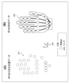
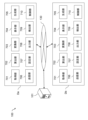
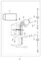
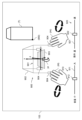
- FIG. 1 is an explanatory diagram showing an example of a system configuration of an electronic device system.
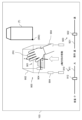
- FIG. 2 is an explanatory diagram showing an example of three-dimensional position data and shape data of a hand.
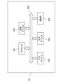
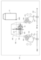
- FIG. 3 is a block diagram illustrating an example of a hardware configuration of the server.
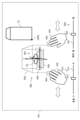
- FIG. 4 is a block diagram showing an example of a hardware configuration of the head mounted display.
- FIG. 5 is an explanatory diagram showing a first alignment configuration example.
- FIG. 6 is an explanatory diagram showing a second alignment configuration example.
- FIG. 7 is a block diagram showing an example of a functional configuration of the electronic device system.
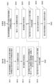
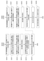
- FIG. 8 is a flowchart illustrating an example of a detailed processing procedure for object-based alignment.
- FIG. 8 is a flowchart illustrating an example of a detailed processing procedure for object-based alignment.
- FIG. 9 is an explanatory diagram showing a display example including an axis object.
- FIG. 10 is an explanatory diagram showing an operation example 1 of an axis object.
- FIG. 11 is an explanatory diagram showing a second operation example of the axis object.
- FIG. 12 is an explanatory diagram showing an operation example 3 of an axis object.
- FIG. 13 is an explanatory diagram showing an operation example 4 of an axis object.
- FIG. 14 is an explanatory diagram showing a fifth example of an axis object operation.
- FIG. 15 is an explanatory diagram showing an operation example 6 of an axis object.
- FIG. 16 is an explanatory diagram showing a first example of a voice output when an axis object and a workpiece are aligned with each other based on the axis object.
- FIG. 17 is an explanatory diagram showing a second example of a voice output when an axis object and a work object are aligned with each other based on the axis object.
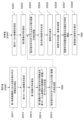
- FIG. 18 is a flowchart of an example of a procedure for the axis object-based alignment process according to the second embodiment.
- FIG. 19 is an explanatory diagram showing a first example of snap processing.
- FIG. 20 is an explanatory diagram showing a second example of snap processing.
- FIG. 21 is a flowchart of an example of a procedure for the axis object-based alignment process according to the third embodiment.
- FIG. 22 is an explanatory diagram showing a first example of a change in the CD ratio.
- FIG. 23 is an explanatory diagram showing a second example of a change in the CD ratio.
- FIG. 24 is a diagram illustrating an example of alignment based on an axis object according to the fourth embodiment.
- FIG. 25 is a flowchart illustrating a detailed example of the process of the axis object-based position adjustment illustrated in FIG.
- FIG. 26 is a flowchart of a detailed example of a process procedure for alignment without a reference according to the fifth embodiment.
- FIG. 27 is an explanatory diagram showing an example of alignment without a reference according to the fifth embodiment.
- ⁇ System configuration example of electronic device system> 1 is an explanatory diagram showing an example of a system configuration of an electronic device system.
- the electronic device system 100 includes a server 101, head mounted displays Da and Db, and a composite device 112. When there is no need to distinguish between the head mounted displays Da and Db, they will be referred to as head mounted display D.
- the server 101 and the head mounted display D are communicatively connected via a network 130 such as the Internet, a LAN (Local Area Network), or a WAN (Wide Area Network).
- a network 130 such as the Internet, a LAN (Local Area Network), or a WAN (Wide Area Network).
- the instructor environment 110 includes a head mounted display Da, a multifunction device 112, instructors S1 and S2, and a first work object TaR.
- the "R" at the end of the first work object TaR is a symbol added to emphasize that it is the real thing. Other symbols also have the "R” added to the end when emphasizing that they are the real thing.
- Head mounted display Da is a display device worn by instructor S1.
- Instructor S2 does not wear head mounted display D.
- Head mounted display D has a camera 102 and a display 103. Note that it is sufficient for either instructor S1 or instructor S2 to be present as an instructor in instructor environment 110.
- the composite device 112 has a TOF (Time Of Flight) camera and a hand tracker.
- the TOF camera captures images of the instructor S2 and the first work object TaR and measures the distance to the objects in the captured three-dimensional space.
- the hand tracker detects the hand of the instructor S2 using infrared rays, recognizes the shape of the hand, and obtains the coordinate values of feature points such as the hand joints and fingertips in the captured three-dimensional space.
- the TOF camera and hand tracker may be provided separately.
- the server 101 recognizes the installation position of the hand tracker based on the coordinate origin of the three-dimensional space captured by the TOF camera, and corrects the coordinate values of feature points such as the hand joints and fingertips detected by the hand tracker so that they become coordinate values in the three-dimensional space captured by the TOF camera.
- the first work object TaR is an actual device, such as a machine tool, that allows the instructor S to demonstrate the operation of the work instructions to the worker W.
- the virtual first work object TaV is a virtual three-dimensional model (virtual object) of the first work object TaR, which is generated by the head-mounted display Da and displayed on the display 103, and is visible to the instructor S1.
- first work object TaV The "V" at the end of virtual first work object TaV is a symbol added to emphasize that it is a virtual object. Other symbols also have a "V” at the end when emphasizing that they are virtual objects. When there is no need to distinguish between first work object TaR and virtual first work object TaV, they are written as first work object Ta.
- the worker environment 120 includes a head-mounted display Db, a worker W, and a second work object TbR.
- the head-mounted display Db is a display device worn by the worker W.
- the second work object TbR is the actual device operated by the worker W, and is, for example, the same type of machine tool as the first work object TaR.
- first work object Ta and the second work object Tb When there is no distinction between the first work object Ta and the second work object Tb, they are referred to as work object T. When there is no distinction between the instructor S and the worker W, they are referred to as users.
- the shape, etc. of the first work object TaR may be simplified compared to the second work object TbR.
- Camera 102 is an image sensor (RGB-D camera) that converts red (R), green (G), and blue (B) light in the visible light range into electrical signals and acquires the distance to the subject, for example, using the TOF method. Camera 102 acquires the three-dimensional position of the subject based on the planar position of the subject on the imaging surface and the distance to the subject.
- RGB-D camera red (R), green (G), and blue (B) light in the visible light range into electrical signals and acquires the distance to the subject, for example, using the TOF method.
- Camera 102 acquires the three-dimensional position of the subject based on the planar position of the subject on the imaging surface and the distance to the subject.
- Display 103 has a display screen. If display 103 is of a video transmission type (video see-through), video captured by or played back by camera 102 is displayed on the display screen. On the other hand, if display 103 is of an optical transmission type (optical see-through), the user can see the real object in front of the user and can display virtual data superimposed on it.
- video transmission type video see-through
- optical see-through optical see-through
- FIG. 2 is an explanatory diagram showing an example of three-dimensional position data and shape data of a hand.
- A shows three-dimensional position data 201 of a hand H in a three-dimensional coordinate system 200 in which an image of the user's hand H is captured.
- B shows shape data 202 of the hand H in the three-dimensional coordinate system 200 in which an image of the user's hand H is captured.
- the hand H of instructor S is written as hand Ha, and the hand H of worker W is written as hand Hb.
- hand Hb When distinguishing between the left and right hand H, add r or l to the end of the symbol.
- instructor S's right hand is written as Har
- instructor S's left hand is written as Hal.
- the three-dimensional position data 201 of the user's hand H is acquired from the camera 102, which is an RGB-D camera that can acquire distance information in addition to an image.
- the three-dimensional position data 201 of the user's hand H is a collection of feature points of the user's hand H.
- the feature points have three-dimensional coordinate values.
- the feature points are, for example, skeletal points that are the fingertips and joints of the user's hand H.
- the feature points may also be points that make up the outline of the user's hand H.
- the shape data 202 of the hand H is generated from three-dimensional position data 201 indicating the three-dimensional position of the hand H. Specifically, for example, if the three-dimensional position data 201 is a collection of skeletal points of the hand H, the shape data 202 of the hand H is generated by connecting the skeletal points along the skeleton of the hand H and generating the outline of the hand H by providing a predetermined width for the skeletal points and the links between the skeletal points. Also, if the three-dimensional position data 201 is a collection of points that make up the outline of the hand H, the shape data 202 of the hand H is generated by connecting adjacent points. Note that the virtual data of the hand H may be configured as a link model in which the skeletal points are linked together, without providing a predetermined width for the links between the skeletal points.
- FIG. 3 is a block diagram showing an example of a hardware configuration of the server 101.
- the server 101 has a processor 301, a storage device 302, an input device 303, an output device 304, and a communication interface (communication IF) 305.
- the processor 301, the storage device 302, the input device 303, the output device 304, and the communication IF 305 are connected by a bus 306.
- the processor 301 controls the server 101.
- the storage device 302 is a working area for the processor 301.
- the storage device 302 is a non-temporary or temporary recording medium that stores various programs and data.
- Examples of the storage device 302 include a read only memory (ROM), a random access memory (RAM), a hard disk drive (HDD), and a flash memory.
- the input device 303 inputs data.
- the input device 303 may be, for example, a keyboard, a mouse, a touch panel, a numeric keypad, a scanner, a microphone, or a sensor.
- the output device 304 outputs data.
- the output device 304 may be, for example, a display, a printer, or a speaker.
- the communication IF 305 is connected to the network 130 and transmits and receives data.
- the head mounted display D includes a processor 301, a storage device 302, a communication IF 305, and a bus 306, as well as an operation device 403, a display 103, a camera 102, a microphone 404, and a speaker 405.
- the operation device 403 accepts various inputs, such as starting, stopping, and pausing the recording of video captured by the camera 102, and starting, stopping, and pausing the playback of the recorded video, through the operation of the instructor S or the worker W.
- the operation device 403 may also accept the recording of still images captured by the camera 102, etc.
- the microphone 404 converts the sound around the head mounted display D into an electrical signal and inputs it into the head mounted display D.
- the speaker 405 converts the electrical signal related to the sound into sound and outputs it outside the head mounted display D.
- communication between the head mounted displays D may be direct or via the server 101.
- ⁇ Object-based alignment> Next, an example of alignment instructed by the instructor S to the worker W will be described.
- One is a case where a work target T exists in both the instructor environment 110 and the worker environment 120 (hereinafter, a first alignment configuration example), which will be described with reference to Fig. 5.
- the other is a case where a second work target TbR exists only in the worker environment 120 out of the instructor environment 110 and the worker environment 120 (hereinafter, a second alignment configuration example), which will be described with reference to Fig. 6.
- FIG. 5 is an explanatory diagram showing a first alignment configuration example.
- the first work object TaR since the first work object TaR exists, either instructor S, S1 or S2, can demonstrate.
- the instructor S demonstrates the operation of a part 510aR of the first work object TaR with the hand HaR.
- a head-mounted display Da When a head-mounted display Da is used, its camera 102 captures an image of the hand HaR and the first work object TaR and displays it on the display 103. Note that even when a head-mounted display Da is used, the TOF camera and hand tracker of the multifunction device 112 may capture an image of the hand HaR.
- the head mounted display Db displays the second work object TbR on the display 103.
- the head mounted display Da or the server 101 may generate virtual data of the hand HaR and transmit the virtual data of the hand HaR to the head mounted display Db.
- the head mounted display Da may transmit the virtual data of the hand HaR directly to the head mounted display Db without going through the server 101.
- the first world coordinate system 501G is the world coordinate system of the instructor environment 110 that defines the three-dimensional space captured by the camera 102 of the head-mounted display Da or the TOF camera of the multifunction device 112 and displayed on the display 103.
- the second world coordinate system 502G is the world coordinate system of the worker environment 120 that defines the three-dimensional space captured by the camera 102 of the head-mounted display Db and displayed on the display 103.
- the hand vector pS is a three-dimensional vector in the first local coordinate system 501L of the hand HaR.
- a hand vector pS exists for each feature point of the shape data 202 of the hand HaR, but for convenience of explanation, in FIG. 5, the hand vector pS of one feature point is shown.
- the head mounted display Da determines the first local coordinate system 501L based on the subject captured by the camera 102. Specifically, for example, the head mounted display Da determines, among the subjects within the imaging range of the camera 102, the subject specified by the instructor S, the subject located at the center of the imaging range, or the subject that corresponds to a specific shape by pattern matching, as the reference subject from which the first local coordinate system 501L is generated. In this example, the first work object TaR is determined as the reference subject.
- the head mounted display Da detects feature points of the first work object TaR, which is the reference subject, and determines the first local coordinate system 501L based on the feature points. Specifically, for example, the head mounted display Da sets the lower left vertex of the front of the first work object TaR facing the instructor S as the origin, the direction of the side connecting the lower left vertex and the lower right vertex as the x-axis, the direction of the side connecting the lower left vertex and the upper left vertex as the y-axis, and the direction perpendicular to the x-axis and y-axis as the z-axis. The head mounted display Da determines the coordinate system consisting of the x-axis, y-axis, and z-axis as the first local coordinate system 501L.
- the head mounted display Da After determining the first local coordinate system 501L, the head mounted display Da sets a first transformation matrix Rt S GL from the first world coordinate system 501G to the first local coordinate system 501L.
- the first transformation matrix Rt S GL is a 4-row, 4-column matrix that defines the rotation and translation from the first world coordinate system 501G to the first local coordinate system 501L.
- the first transformation matrix Rt S GL is a matrix that matches the position of the origin, the x-axis and the X-axis, the y-axis and the Y-axis, and the z-axis between the first local coordinate system 501L and the first world coordinate system 501G.
- the head mounted display Da acquires the shape data 202 of the hand HaR detected in the first world coordinate system 501G. Since the coordinate values of each feature point of the shape data 202 of the hand HaR are coordinate values of the first world coordinate system 501G, the head mounted display Da transforms the coordinate values of each feature point of the shape data 202 of the hand HaR into coordinate values of the first local coordinate system 501L using the first transformation matrix Rt S GL , and generates a hand vector p S for each feature point.
- Shape data 202 of the hand HaR which is a collection of hand vectors pS , is transmitted from the head mounted display Da or the multifunction device 112 to the head mounted display Db via the server 101. Because the hand HaR moves, the head mounted display Da sequentially transmits the hand vector pS to the head mounted display Db, but because the first transformation matrix RtSGL has a fixed value, the head mounted display Da needs to transmit the first transformation matrix RtSGL only the first time.
- the head mounted display Db sets the second local coordinate system 502L using, for example, the second work object TbR in a similar manner to the head mounted display Da.
- the head mounted display Db sets a second transformation matrix RtWGL from the second world coordinate system 502G to the second local coordinate system 502L .
- the second transformation matrix RtWGL is a 4-row, 4-column matrix that specifies the rotation and translation from the second world coordinate system 502G to the second local coordinate system 502L.
- the head mounted display Db generates virtual data of the hand HaR based on the shape data 202 of the hand HaR from the head mounted display Da, and displays it as a virtual hand HaV on the display 103 of the head mounted display Db. Specifically, for example, the head mounted display Db generates a hand vector pw of the feature point of the virtual hand HaV by the following formula (1) using the hand vector ps, the first transformation matrix RtSGL , and the second transformation matrix RtWGL .
- a collection of hand vectors pw of each feature point is displayed as a virtual hand HaV on the display 103 of the head mounted display Db.
- the three-dimensional positions of the virtual hand HaV and the second work object TbR correspond to the three-dimensional positions of the hand HaR and the first work object TaR of the instructor S.
- a demonstration of the operation of a part 510bR (corresponding to the part 510aR) of the second work object TbR with the virtual hand HaV is displayed on the display 103 of the head mounted display Db.
- FIG. 6 is an explanatory diagram showing a second alignment configuration example.
- the first work object TaR since the first work object TaR does not exist, only instructor S1 of instructors S1 and S2 can demonstrate.
- the camera 102 of the head mounted display Da captures an image of the hand HaR and displays it on the display 103, and a virtual first work object TaV is displayed on the display 103 in place of the first work object TaR that does not exist within the imaging range of the head mounted display Da.
- the display 103 is an optically transparent type (optically see-through), the hand HaR, which can be observed through the display 103, can be viewed on the display screen.
- the coordinate transformation from the instructor environment 110 to the worker environment 120 in the case of FIG. 6 is the same as the example shown in FIG. 5.
- the virtual first work object TaV whose coordinate values in the first world coordinate system 501G are set, can be used as the reference subject.
- the instructor S1 demonstrates the operation of a part 510aV of the virtual first work object TaV with the hand HaR.
- the shape data 202 of the hand HaR is transmitted to the head mounted display Db via the head mounted display Da.
- the head mounted display Db generates virtual data of the hand HaR based on the shape data 202 of the hand HaR, and displays it as the virtual hand HaV on the display 103 of the head mounted display Db together with the second work object TbR.
- the three-dimensional positions of the virtual hand HaV and the second work object TbR in the second world coordinate system 502G that defines the three-dimensional space captured by the camera 102 of the head mounted display Db correspond to the three-dimensional positions of the hand HaR of the instructor S1 and the virtual first work object TaV in the first world coordinate system 501G that defines the three-dimensional space captured by the camera 102 of the head mounted display Da.
- a demonstration of the operation of a part 510bR (corresponding to part 510aV) of the second work object TbR with the virtual hand HaV is displayed on the display 103 of the head mounted display Db.
- the head mounted display D has an acquisition unit 701, a calculation unit 702, a conversion unit 703, a display unit 704, a generation unit 705, a transmission unit 706, a setting unit 707, an output unit 708, a detection unit 709, and a control unit 710 as functions available on both the head mounted displays Da and Db so that the head mounted display D may be used by either the instructor or the worker.
- the head mounted display D may have a function available on only one of the head mounted displays Da and Db.
- the server 101 may also have any of the functions of an acquisition unit 701, a calculation unit 702, a conversion unit 703, a display unit 704, a generation unit 705, a transmission unit 706, a setting unit 707, an output unit 708, a detection unit 709, and a control unit 710.
- the server 101 can execute the functions in place of the head mounted display D, thereby reducing the load on the head mounted display D.
- acquisition unit 701, calculation unit 702, conversion unit 703, display unit 704, generation unit 705, transmission unit 706, setting unit 707, output unit 708, detection unit 709, and control unit 710 are specifically realized, for example, by having the processor 301 execute a program stored in the storage device 302.
- the acquisition unit 701 acquires various data. Specifically, for example, the acquisition unit 701 receives data from the server 101 or the other head mounted display D. The acquisition unit 701 also acquires image data of a subject captured by the camera 102. The acquisition unit 701 also acquires audio data from the microphone 404. The acquisition unit 701 also acquires image data of a subject captured by the multifunction device 112 and the distance to the subject. The acquisition unit 701 also acquires the coordinate values of feature points of the hand detected by the multifunction device 112.
- the calculation unit 702 calculates matrices.
- the matrices include, for example, a first transformation matrix for transforming from the first world coordinate system 501G to the first local coordinate system 501L, a second transformation matrix for transforming from the second world coordinate system 502G to the second local coordinate system 502L, and a correction matrix for transforming an object into an object with a changed position or orientation when the position or orientation of the object is changed.
- the correction matrix will be described later in Example 5.
- the conversion unit 703 performs conversion of various data. For example, the conversion unit 703 converts the shape data 202 of the hand HaR into virtual data of the hand HaR, i.e., virtual hand HaV, using a first conversion matrix and a second conversion matrix.
- the display unit 704 displays image data of the subject captured by the camera 102 or the multifunction device 112, various data acquired by the acquisition unit 701, and data generated within the head-mounted display D.
- the generation unit 705 generates shape data of the hand H by converting the feature points of the hand in the world coordinate system into values in the local coordinate system.
- the transmitting unit 706 transmits data to the server 101 or the other head mounted display D.
- the transmitted data is, for example, a transformation matrix and shape data of the hand H.
- the setting unit 707 sets an axis object, which is an object in a coordinate system that can be operated by the user in the world coordinate system, in the local coordinate system.
- the axis object will be described later in Example 2 and onwards.
- the output unit 708 outputs various data. Specifically, for example, the output unit 708 outputs or stops audio from the speaker 405, and displays data on a display. The output contents of the output unit 708 will be described later in Example 2.
- the detection unit 709 detects feature points of an object.
- the object is three-dimensional data of a hand H or a work object T.
- the three-dimensional data of the work object T may be an actual work object T or a virtual object.
- the detection unit 709 also detects a change operation of the position or posture of the virtual hand. The detection of a change operation will be described later in Example 5.
- the control unit 710 controls the position of the axis object according to the interference state between the hand H object and the axis object.
- the control contents of the control unit 710 will be described later in Example 2.
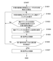
- FIG. 8 is a flowchart showing a detailed example of the processing procedure for the object-based alignment shown in FIGS. 5 and 6.
- the head-mounted display Da detects the feature points of the first work object Ta and the feature points of the instructor S's hand HaR in the first world coordinate system 501G (step S811).
- the first work object Ta for example, a part constituting the first work object Ta (e.g., a push button) or a mark affixed to the first work object Ta may be used.
- the instructor S may specify the first work object Ta stored in advance in the head-mounted display Da or the server 101, and the head-mounted display Da may automatically recognize the first work object Ta by image analysis using the camera 102.
- the shape of the first work object Ta but also color information may be used to recognize the first work object Ta.
- the first work object Ta may be automatically recognized using a captured two-dimensional image or depth information combined with the image.
- the head mounted display Da sets the first local coordinate system 501L based on the feature points of the first work object Ta (step S812).
- the head mounted display Da calculates a first transformation matrix Rt S GL for transformation from the first world coordinate system 501G to the first local coordinate system 501L (step S813).
- the head mounted display Da transforms the feature points of the hand HaR of the instructor S into coordinate values of the first local coordinate system 501L using the first transformation matrix Rt S GL to generate a hand vector p S (step S814).
- the head mounted display Da transmits the hand vector p s and the first transformation matrix Rt S GL of the hand HaR of the instructor S to the head mounted display Db (step S815).
- the head mounted display Db detects feature points of the second work object Tb in the second world coordinate system 502G (step S821).
- the head mounted display Db sets the second local coordinate system 502L based on the feature points of the second work object TbR (step S822).
- the head mounted display Db calculates the second transformation matrix Rt W GL for transformation from the second world coordinate system 502G to the second local coordinate system 502L (step S823).
- the head mounted display Db receives the hand vector p s and the first transformation matrix Rt S GL of the hand HaR of the instructor S from the head mounted display Da (step S824).
- the head mounted display Db generates the virtual hand HaV in the second world coordinate system 502G using the second transformation matrix Rt W GL , the hand vector p S of the hand HaR of the instructor S, and the first transformation matrix Rt S GL (step S825).
- the head-mounted display Db displays the virtual hand HaV together with the second work object TbR (step S826).
- the head mounted display Db may compare feature points of the first work object Ta with feature points of the second work object (Tb). Specifically, for example, in step S814, the head mounted display Da converts the feature points of the first work object Ta into coordinate values of the first local coordinate system 501L using the first transformation matrix Rt S GL to generate a vector of the first work object Ta, and transmits the vector to the head mounted display Db in step S815.
- the head mounted display Db receives the vector of the first work object Ta in step S824, and generates feature points of the first work object Ta in the second local coordinate system 502L in step S825, similar to the generation of the virtual hand HaV.
- the head mounted display Db uses the second transformation matrix Rt W GL to transform the coordinate values of the feature points of the second work object TbR from the second world coordinate system 502G to the second local coordinate system 502L.
- the head mounted display Db compares the feature points of the first work object Ta in the second local coordinate system 502L with the feature points of the second work object TbR in the second local coordinate system 502L. Specifically, for example, when the lower left vertex of the front of the first work object Ta is matched with a specific feature point in the shape of the second work object Tb (for example, the lower left vertex of the front of the second work object Tb as seen by the worker W), it is the sum of the deviations between other adjacent feature points in both shapes. If the difference between the two shapes is within the allowable range, the comparison is successful, and step S826 is executed. If the difference between the two shapes is outside the allowable range, the comparison is unsuccessful, and step S726 is not executed.
- the positional relationship between the three-dimensional position of the hand HaR moved by the instructor S in the instructor environment 110 and the three-dimensional position of the first work object Ta corresponds to the positional relationship between the three-dimensional position of the virtual hand HaV displayed on the display 103 of the head-mounted display Db in the worker environment 120 and the three-dimensional position of the second work object Tb.
- the display 103 of the head-mounted display Db in the worker environment 120 also displays the virtual hand HaV operating the second work object Tb at a position corresponding to the hand HaR, following the movement of the instructor S operating the first work object Ta with the hand HaR.
- the instructor S can freely set the reference subject by arbitrarily selecting the subject to be imaged by the camera 102 using the head mounted display Da, making it easier to determine the first local coordinate system 501L.
- the user can set the local coordinate system at any position or posture by manipulating the axis object 900, improving the degree of freedom in setting the local coordinate system.
- the server 101 may collect data necessary for executing steps S821 to S825 from the head mounted display Db, execute steps S821 to S825, and the head mounted display Db may execute step S826.
- Alignment based on an axis object is an object in a coordinate system that can be operated by a user in a world coordinate system.
- Alignment based on an axis object is a process of aligning the real work target object T with the axis object as a reference in the first alignment configuration example (FIG. 5) and the second alignment configuration example (FIG. 6).
- Alignment based on an axis object is applicable when the display 103 of the head mounted display D is a video transmission type (video see-through).
- the display 103 of the head mounted display D is an optical see-through type
- the head mounted display D is equipped with a camera
- the user's actual hand or the actual first work object Ta in the first alignment configuration example can be recognized by image, making alignment based on the axis object possible.
- [Axis Object] 9 is an explanatory diagram showing a display example including an axis object.
- the axis object 900 is a three-dimensional object displayed on the display 103. That is, the axis object 900 is displayed on each of the head mounted displays Da and Db.
- the axis object 900 has an axis coordinate system 901, a frame 902 surrounding the axis coordinate system 901, an xz plane portion 903, and a knob 904.
- the axis coordinate system 901 has an x-axis, a y-axis, a z-axis, and an origin o.
- the x-axis, y-axis, and z-axis are mutually perpendicular.
- the x-axis indicates the horizontal direction of the display 103
- the y-axis indicates the vertical direction of the display 103
- the z-axis indicates the depth direction of the display 103.
- the origin o is the intersection of the x-axis, y-axis, and z-axis.
- the arrowheads of the x-axis, y-axis, and z-axis indicate the positive directions.
- the x-axis, y-axis, and z-axis enable parallel translation operations of the axis object 900.
- Frame 902 is composed of a rectangle parallel to the xz plane and line segments extending in the y direction from the vertices of the rectangle.
- Xz plane portion 903 is a figure obtained by extracting a rectangle centered on origin o from the xz plane spanned by the x and z axes.
- Knob 904 is an object provided at the tip of a line segment extending in the y direction from the vertices of the rectangle of frame 902, and enables rotational operation of axis object 900.
- an object of the user's real right hand Hr is represented as right hand (Hr)
- an object of the real left hand Hl is represented as left hand (Hl)
- an object of the real work object T is represented as work object (T).
- the volume adjustment section 910 is a graphic user interface that can adjust the volume output from the speaker 405 of the head mounted display D, and has a slide shaft 911 and a slider 912.
- the volume from the speaker 405 increases or decreases.
- the operation speed adjustment unit 920 is a graphic user interface that can adjust the movement speed of the axis object 900 displayed on the display 103 of the head mounted display D, and has a slide axis 921 and a slider 922.
- the movement speed of the axis object 900 operated by the user increases or decreases.
- the operation speed adjustment unit 920 may also be capable of increasing or decreasing the moving speed of the hand (H).
- a separate operation speed adjustment unit (not shown) may be displayed on the display 103.
- the graphic user interface may be configured to accept operations by moving the user's hand (H) in a specified direction.
- the lower left vertex of the front face of the vertices of the work object (T) is set as vertex (950).
- the user aligns the origin o to vertex (950).
- FIG. 10 is an explanatory diagram showing an example 1 of an axis object operation.
- Fig. 10 shows an example of an operation in which an axis object 900 is translated in the x-axis direction.
- a user's hand (Hr) is moved in the x-axis direction by moving the hand (Hr) in the x-axis direction in a state in which the hand (Hr) is interfering with a part of the x-axis (for example, the tip (arrowhead) of the x-axis)
- the axis object 900 moves in the x-axis direction.
- the movement direction of the user's hand Hr may include the y-axis and z-axis directions in addition to the x-axis direction, but when the hand (Hr) is interfering with part of the x-axis, the axis object 900 moves based on the movement component of the hand (Hr) in the x-axis direction.
- FIG. 11 is an explanatory diagram showing a second example of axis object operation.
- FIG. 11 shows an example of operation in which the axis object 900 is translated in the y-axis direction.
- the axis object 900 moves in the y-axis direction.
- the movement direction of the user's hand Hr may include the x-axis and z-axis directions in addition to the y-axis direction, but when the hand (Hr) is interfering with part of the y-axis, the axis object 900 moves based on the movement component of the hand (Hr) in the y-axis direction.
- FIG. 12 is an explanatory diagram showing an axis object operation example 3.
- FIG. 12 shows an operation example in which the axis object 900 is translated in the z-axis direction.
- a user's hand (Hr) is moved in the z-axis direction by moving the hand Hr in the z-axis direction while the hand (Hr) is interfering with a part of the z-axis (for example, the tip of the z-axis (arrowhead portion)
- the axis object 900 moves in the z-axis direction.
- the movement direction of the user's hand Hr may include the x-axis and y-axis directions in addition to the z-axis direction, but when the hand (Hr) is interfering with part of the z-axis, the axis object 900 moves based on the movement component of the hand (Hr) in the z-axis direction.
- the user can select the free adjustment mode (not shown) and move the user's right hand (Hr) in the desired direction while interfering with one of the x-axis, y-axis, and z-axis, thereby moving the user's hand Hr in the desired direction, thereby moving the axis object 900 in any direction.
- FIG. 13 is an explanatory diagram showing axis object operation example 4.
- FIG. 13 shows an operation example in which the axis object 900 is rotated around the x-axis.
- the axis object 900 rotates around the x-axis.
- the direction of rotation around the x-axis is denoted as Rx.
- the movement direction of the user's hands Hr and Hl may include the x-axis and z-axis directions in addition to the y-axis direction, but when the hands (Hr) and (Hl) are in contact with the knob 904, the axis object 900 rotates around the x-axis based on the movement component of the hands (Hr) and (Hl) in the y-axis direction.
- FIG. 14 is an explanatory diagram showing axis object operation example 5.
- FIG. 14 shows an operation example in which the axis object 900 is rotated around the y-axis.
- the axis object 900 rotates around the y-axis.
- Py The direction of rotation around the y-axis is denoted as Py.
- the movement direction of the user's hands Hr and Hl may include the y-axis and z-axis directions in addition to the x-axis direction, but when the hands (Hr) and (Hl) are in contact with the knob 904, the axis object 900 rotates around the y-axis based on the movement component of the hands (Hr) and (Hl) in the x-axis direction.
- FIG. 15 is an explanatory diagram showing axis object operation example 6.
- FIG. 15 shows an operation example in which the axis object 900 is rotated around the z-axis.
- the axis object 900 rotates around the z-axis.
- the direction of rotation around the z-axis is denoted as yz.
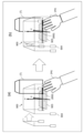
- FIG. 16 is an explanatory diagram showing a first example of audio output when aligning an axis object 900 with a work target (T) based on the axis object.
- the movement of the axis object 900 in the x-axis direction (Fig. 10) is taken as an example for explanation, but the same applies to the movement in the y-axis direction (Fig. 11), the movement in the z-axis direction (Fig. 12), the rotation in the Rz direction (Fig. 13), the rotation in the Py direction (Fig. 14), and the rotation in the yz directions (Fig. 15).
- (a) shows the state where the origin o coincides with the vertex (950) of the work object (T) by moving the axis object 900 in the x-axis direction by the operation shown in FIG. 10.
- (b) shows the state where, in the state of (a), the user moves the right hand Hr in the z-axis direction, thereby moving the right hand (Hr) away from the x-axis in the z-axis direction.
- the origin o will be displaced in the x-axis direction from the vertex (950) of the work object (T).
- the real right hand Hr cannot directly touch the axis object 900, the user cannot tactilely sense the distance of the right hand Hr from the x-axis.
- the head mounted display D when the head mounted display D is in state (a), i.e., when the right hand (Hr) is interfering with the x-axis, it outputs sound s1 indicating the interference from the speaker 405. Then, when the state (a) transitions to state (b) (when the right hand (Hr) moves away from the x-axis), the head mounted display D changes the output sound from sound s1 to sound s2 and outputs it from the speaker 405, or stops sound s1 to enter a silent state. This allows the user to auditorily recognize that the right hand Hr has moved away from the x-axis.
- FIG. 17 is an explanatory diagram showing a second example of audio output when aligning the axis object 900 and the work object (T) based on the axis object.
- (c) shows the state of movement of the axis object 900 in the x-axis direction by the operation shown in FIG. 10.
- (d) shows the state in which the origin o and the vertex (950) of the work object (T) coincide with each other due to the movement in (c) (similar to (a) in FIG. 16).
- (e) shows the state in which, in the state of (d), the user moves his right hand Hr in the z-direction, thereby moving the right hand (Hr) away from the x-axis in the z-axis direction (similar to (b) in FIG. 16).
- the head mounted display D outputs sound s1 indicating the interference from the speaker 405. Then, when transitioning from state (d) to state (e), the head mounted display D changes the output sound from sound s1 to sound s2 and outputs it from the speaker 405, or stops sound s1 and goes into a silent state. This allows the user to auditorily recognize the distance from the x-axis with the right hand Hr.
- the head mounted display D outputs sound s1a indicating the interference from the speaker 405. Then, when the state transitions from (c) to (d), the head mounted display D changes the output sound from sound s1a to sound s1b and outputs the changed sound from the speaker 405.
- the head mounted display D changes the output sound from sound s1b to sound s2 and outputs it from the speaker 405, or stops sound s1b to become silent. This allows the user to auditorily recognize that the right hand Hr has stopped moving in the x-axis direction and is moving away from the x-axis.
- the alignment based on the axis object i.e., the coordinate conversion, is basically the same as that shown in the first embodiment (FIGS. 5, 6, and 8). The difference is that in the first embodiment, the head mounted display Da determines the first local coordinate system 501L based on the subject captured by the camera 102, but in the second embodiment, the axis coordinate system 901 of the axis object 900 of the head mounted display Da becomes the first local coordinate system 501L, and the axis coordinate system 901 of the axis object 900 of the head mounted display Db becomes the second local coordinate system 502L.
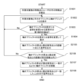
- [Axis object-based positioning process procedure] 18 is a flowchart showing an example of a procedure for a positioning process based on an axis object according to the second embodiment.
- the head mounted display D captures an image of a subject including a work target T and a user's hand H using the camera 102, and detects feature points of the work target T and feature points of the user's hand H in the axis coordinate system 901 (step S1801).
- the feature points of the work target T are, for example, vertices of the work target T, including the vertex (950).
- the head mounted display D displays on the display 103 the subjects including the work object (T) and the user's hand (H) captured by the camera 102, and the axis object 900 (step S1802).
- the head mounted display D attempts to detect a first movement of the hand (H) that changes the position or posture of the axis object 900 (step S1802).
- the first movement is, for example, a movement operation of the axis object 900 by moving the right hand (Hr) shown in Figures 10 to 12, or a rotation operation of the axis object 900 by moving the right hand (Hr) shown in Figures 13 to 15.
- step S1803: No If the first movement is not detected (step S1803: No), the process returns to step S1802. If the first movement is detected (step S1803: Yes), the head mounted display D changes the position or posture of the axis object 900 according to the first movement and displays it (step S1804).
- the head mounted display D executes the first audio output control with a volume according to the position of the slider 912 of the volume adjustment unit 910 (step S1805).
- the first audio output control is, for example, output of audio s1 in the state of FIG. 16(a), output of audio s1 in the states of FIG. 17(c) and (d), output of audio s1a in the state of FIG. 17(c), and output of audio s1b in the state of FIG. 17(d).
- the head mounted display D attempts to detect a second action that ends the first action (step S1806).
- the second action is, for example, the action of the user's hand Hr moving the right hand (Hr) away from the x-axis of the axis object 900 shown in FIG. 16(b), or the action of the user's hand Hr moving the right hand (Hr) away from the x-axis of the axis object 900 shown in FIG. 17(e).
- step S1806: No If the second movement is not detected (step S1806: No), the process returns to step S1802. If the second movement is detected (step S1806: Yes), the head mounted display D executes the second audio output control with a volume corresponding to the position of the slider 912 of the volume adjustment unit 910 (step S1807).
- Specific examples of the second audio output control include outputting audio s2 in the state of FIG. 16(b), stopping audio s1 and outputting audio s2 in the state of FIG. 17(e), stopping audio s1 in the state of FIG. 17(e) (audio s2 is not output), stopping audio s1b and outputting audio s2 in the state of FIG. 17(e), and stopping audio s1b in the state of FIG. 17(e) (audio s2 is not output).
- the user can auditorily recognize when the hand (h) is moving away from the parts of the axis object 900 whose position or orientation can be changed (the arrowheads of the x-axis, y-axis, and z-axis, and the knobs 904).
- the positional relationship between the three-dimensional position of the hand HaR moved by the instructor S in the instructor environment 110 and the three-dimensional position of the first work object Ta corresponds to the positional relationship between the three-dimensional position of the virtual hand HaV displayed on the display 103 of the head-mounted display Db in the worker environment 120 and the three-dimensional position of the second work object Tb.
- the display 103 of the head-mounted display Db in the worker environment 120 also displays the virtual hand HaV operating the second work object Tb at a position corresponding to the hand (Ha), following the movement of the instructor S operating the first work object Ta with the hand (Ha).
- the head mounted display D controls the sound output when the axis object 900 and the hand (H) are interfering with each other and when the hand (H) is moving away from the axis object 900.
- the head mounted display D may output sounds s1 and s1a (or sounds different from sounds s1 and s1a) and may also change the volume of the type of sound.
- the information regarding the interference and separation between the hand (H) and the axis object 900 is output and controlled by voice, but the information regarding at least the separation among the interference and separation between the hand (H) and the axis object 900 may be output and controlled by displaying it on the display 103.
- the head mounted display D may blink the part of the axis object 900 that is in contact with the hand (H) and that can be operated to change the position or posture (the arrowheads of the x-axis, y-axis, and z-axis, and the knobs 904), change the color of the hand (H), or display a character string on the display 103 indicating that the axis object 900 can be operated, such as "The x-axis can be operated.”
- the head mounted display D may stop blinking of the parts of the axis object 900 that can be operated to change the position or posture (the arrowheads of the x-axis, y-axis, and z-axis, and the knobs 904) that are separated from the hand (H), stop the color change of the hand (H), or display a character string on the display 103 indicating that operation is not possible, such as "x-axis operation is no longer possible.”
- the head mounted display D may execute output control of both audio and display with respect to the above-mentioned audio and display.
- the display control may be performed when the axis object 900 and the hand (H) are in contact with each other, and the audio output control may be performed when the hand (H) is separated from the axis object 900 (or vice versa).
- the head mounted display D may execute output control of sound and display in the same manner as the axis object 900, in response to interference or separation between the hand (H) and a graphic user interface such as the slider 912 of the volume adjustment unit 910 and the slider 922 of the operation speed adjustment unit 920.
- a graphic user interface such as the slider 912 of the volume adjustment unit 910 and the slider 922 of the operation speed adjustment unit 920.
- the origin o and the vertex (950) of the work object (T) coincide with each other, the type or volume of sound may be changed, or the color of the coordinate axis may be changed.
- the third embodiment is an example in which an axis object 900 is snapped in the axis object-based positioning shown in the second embodiment. Snapping is a process in which, when two objects are close to each other, one object is moved so that it interferes with the other.
- Example 3 will be described with reference to Figures 19 to 21. Note that in Example 2, in order to describe the differences from Example 1, the same reference numerals are used for the parts common to Example 1, and the description thereof will be omitted.
- FIG. 19 is an explanatory diagram showing snap processing example 1.
- (a) shows the state before snapping
- (b) shows the state after snapping.
- the part of the axis object 900 that is the subject of one snap judgment is, for example, the origin o.
- the part of the work object (T) that is the subject of the other snap judgment is, for example, the group of vertices of the work object (T) (including vertex (950)).
- the head mounted display D calculates the distance between the origin o and each vertex of the group of vertices of the work object (T). In (a), it is assumed that the distance between the origin o and the vertex (950) is the shortest.
- the head mounted display D determines whether the shortest calculated distance among the calculated distances is within a predetermined distance. If it is within the predetermined distance, as shown in (b), the head mounted display D moves the axis object 900 in the x-axis direction by the shortest calculated distance, so that the origin o and the vertex (950) coincide with each other. This makes it possible to prevent misalignment between the origin o and the vertex (950) when moving away from the axis object 900.
- FIG. 20 is an explanatory diagram showing snap processing example 2.
- (c) shows the interference between the hand (Hr) and the arrowhead of the x-axis
- (d) shows before the snap
- (e) shows after the snap.
- the part of the axis object 900 that is the subject of one snap judgment is, for example, the origin o.
- the part of the work object (T) that is the subject of the other snap judgment is, for example, the group of vertices of the work object (T) (including vertex (950)).
- Graph 2000 shows the change in audio output before and after a snap.
- the horizontal axis of graph 2000 is time, and the vertical axis is audio frequency.
- the hand (Hr) interferes with the arrowhead on the x-axis, and over time, the axis object 900 also moves in the x-axis direction due to the movement of the hand (Hr) in the x-axis direction.
- head mounted display D determines that the shortest calculated distance between the origin o and each vertex is not within a predetermined distance. As the shortest distance becomes shorter, the frequency of the audio output from speaker 405 becomes higher.
- the head mounted display D determines that the shortest calculated distance among the calculated distances between the origin o and each vertex is within a predetermined distance. In this case, the head mounted display D moves the axis object 900 in the x-axis direction by the shortest calculated distance, executes a snap to match the origin o with the vertex (950), and further outputs a sound with a higher frequency to indicate that the snap has been made.
- the frequency of the sound is increased as the distance between the origin o and the shortest calculated distance becomes shorter, but it is also possible to decrease the frequency of the sound as the distance between the origin o and the shortest calculated distance becomes shorter. Also, instead of the frequency, the volume may be increased or decreased, and the sound pattern may also be changed.
- ⁇ Procedure for position alignment based on axis object> 21 is a flowchart illustrating an example of a procedure for processing alignment based on an axis object according to the embodiment 3. Steps S1801 to S1804 are the same as those in the embodiment 2, so steps S2105 to S2108 will be described.
- the head mounted display D outputs from the speaker 405 a sound according to the distance between the origin o of the axis object 900 and the closest vertex (vertex (950) in the above example) (step S2105).
- Step S2105 is the sound output in (c) and (d) of FIG. 20. If no sound is output as in FIG. 19, step S2105 is not executed.
- the head mounted display D determines whether the distance between the origin o of the axis object 900 and the nearest vertex is within a predetermined distance (step S2105). If it is not within the predetermined distance (step S2106: No), the process returns to step S1802. On the other hand, if it is within the predetermined distance (step S2106: Yes), the head mounted display D moves the axis object 900 so that the origin o of the axis object 900 coincides with the nearest vertex, as shown in FIG. 19(b) and FIG. 20(e) (step S2107).
- the head mounted display D outputs from the speaker 405 a sound indicating that the origin o of the axis object 900 and the closest vertex coincide (step S2108).
- Step S2105 is the sound output in (e) of FIG. 20. If no sound is output as in FIG. 19, step S2108 is not executed.
- step S2106 in FIG. 21 if the predetermined distance in step S2106 in FIG. 21 is set to 0, the configuration will be the same as in Example 2 where snapping is not performed, but the sound change will be frequency dependent.
- the degree of proximity between the origin o and the nearest vertex may be communicated to the user by changes in display, such as blinking or color changes.
- the operation speed of the axis object 900 by the hand (H) is adjusted using the operation speed adjustment unit 920 displayed on the display 103 as a graphic user interface, but the control display ratio (CD) may be changed by detecting the direction of the hand H.
- FIG. 22 is an explanatory diagram showing a first example of change in the CD ratio.
- (a) shows an example where the CD ratio is 1 (the back of the right hand is horizontal)
- (b) shows an example where the CD ratio is 0.5 (the back of the right hand is rotated 45 degrees from (a) around the finger Fr as the axis of rotation)
- (c) shows an example where the CD ratio is 0.25 (the back of the right hand is rotated 90 degrees from (a) around the finger Fr as the axis of rotation) (the same applies to FIG. 23 described later).
- the head mounted display D sets the CD ratio to 1. Therefore, for a finger (Fr) that interferes with the arrowhead of the x-axis, the axis object 900 is moved in the x-axis direction by a movement amount m so that the CD ratio becomes 1.
- m is the movement amount of the finger (Fr).
- the head mounted display D sets the CD ratio to 0.5. Therefore, the finger (Fr) interfering with the arrowhead of the x-axis moves the axis object 900 in the x-axis direction by a movement amount m/2 so that the CD ratio becomes 0.5.
- the head mounted display D sets the CD ratio to 0.25. Therefore, the finger (Fr) interfering with the arrowhead of the x-axis moves the axis object 900 in the x-axis direction by a movement amount m/4 so that the CD ratio becomes 0.25.
- FIG. 23 is an explanatory diagram showing a second example of change in the CD ratio.
- the user specifies in advance the direction (x-axis, y-axis, z-axis) in which the axis object 900 is to be moved.
- the x-axis is specified.
- the rotation operation direction (Rx, Py, yz) for example, a combination of different knobs 904 may be specified.
- a movement amount adjustment unit 2300 is displayed on the display 103 of the head mounted display D.
- the movement amount adjustment unit 2300 is a graphic user interface that can adjust the movement amount of the axis object 900 according to the CD ratio, and has a slide axis 2301 and a slider 2302.
- the movement amount of the axis object 900 by the user's operation increases or decreases.
- the CD ratio 1, so the amount of movement of the finger (Fr) in the x-axis direction and the amount of movement of the axis object 900 in the x-axis direction are both m.
- the CD ratio 0.5, so when the amount of movement of the finger (Fr) in the x-axis direction is m, the amount of movement of the axis object 900 in the x-axis direction is m/2.
- the CD ratio 0.25, so when the amount of movement of the finger (Fr) in the x-axis direction is m, the amount of movement of the axis object 900 in the x-axis direction is m/4.
- the CD ratio is set based on the shape and posture of the right hand Hr, but the left hand Hl may also be used. Also, instead of the shape of the hand H, the CD ratio may be set based on the part of the hand (H) that interferes with the part that changes the position or posture of the axis object 900 (the arrowheads of the x-axis, y-axis, and z-axis, and the knob 904), in this example, the size of the nail area of the finger (Fr). That is, since the nail area increases in the order of (a) to (c) in Figs. 22 and 23, the head mounted display D can set the CD ratio according to the size of the nail area.
- a mode switching button (not shown) is provided for switching between the movement speed and movement amount of the coordinate axes, and when the movement speed mode is selected, the movement speed of the coordinate axes may be changed according to the shape and posture of the right hand Hr.
- the movement speed of the coordinate axes can be made faster, and in the case of the shape and posture of the right hand Hr shown in FIG. 22(b), the movement speed of the coordinate axes can be made slower.
- Example 4 is an example of axis object-based alignment in Examples 2 and 3.
- Fig. 24 is an explanatory diagram showing an example of alignment based on an axis object according to the fourth embodiment.
- the hand vector pS is a three-dimensional vector in the first local coordinate system 501L of the hand HaR.
- a hand vector pS exists for each feature point of the shape data 202 of the hand HaR, but for convenience of explanation, Fig. 23 shows the hand vector pS of one feature point.
- the head mounted display Da detects the axis object 900 (hereinafter referred to as the first axis object 900a) that has been set as the reference subject, and determines the first local coordinate system 501L.
- the head mounted display Da determines the axis coordinate system 901 consisting of the origin o, x-axis, y-axis, and z-axis of the first axis object 900a as the first local coordinate system 501L.
- the head mounted display Da After determining the first local coordinate system 501L, the head mounted display Da sets a first transformation matrix Rt S GL from the first world coordinate system 501G to the first local coordinate system 501L.
- the first transformation matrix Rt S GL is a 4-row, 4-column matrix that defines the rotation and translation from the first world coordinate system 501G to the first local coordinate system 501L.
- the first transformation matrix Rt S GL is a matrix that matches the position of the origin, the x-axis and the X-axis, the y-axis and the Y-axis, and the z-axis between the first local coordinate system 501L and the first world coordinate system 501G.
- the head mounted display Da acquires the shape data 202 of the hand HaR detected in the first world coordinate system 501G. Since the coordinate values of each feature point of the shape data 202 of the hand HaR are coordinate values of the first world coordinate system 501G, the head mounted display Da transforms the coordinate values of each feature point of the shape data 202 of the hand HaR into coordinate values of the first local coordinate system 501L using the first transformation matrix Rt S GL , and generates a hand vector p S for each feature point.
- Shape data 202 of the hand HaR which is a set of hand vectors pS , is transmitted from the head mounted display Da or the multifunction device 112 to the head mounted display Db via the server 101. Because the hand HaR moves, the head mounted display Da sequentially transmits the hand vector pS to the head mounted display Db, but because the first transformation matrix RtSGL has a fixed value, the head mounted display Da needs to transmit the first transformation matrix RtSGL only the first time.
- the head mounted display Db sets the second local coordinate system 502L using, for example, an axis object 900 (hereinafter referred to as a second axis object 900b) in a similar manner to the head mounted display Da.
- the head mounted display Db sets a second transformation matrix RtWGL from the second world coordinate system 502G to the second local coordinate system 502L.
- the second transformation matrix RtWGL is a 4-row, 4-column matrix that specifies the rotation and translation from the second world coordinate system 502G to the second local coordinate system 502L.
- the head mounted display Db generates virtual data of the hand HaR based on the shape data 202 of the hand HaR from the head mounted display Da, and displays it as a virtual hand HaV on the display 103 of the head mounted display Db. Specifically, for example, the head mounted display Db generates a hand vector pw of the feature point of the virtual hand HaV by the above formula (1) using the hand vector ps, the first transformation matrix RtSGL , and the second transformation matrix RtWGL .
- a collection of hand vectors pw of each feature point is displayed as a virtual hand HaV on the display 103 of the head mounted display Db.
- the three-dimensional positions of the virtual hand HaV and the second axis object 900b correspond to the three-dimensional positions of the hand HaR and the first axis object 900a of the instructor S. That is, a demonstration of the operation of a part 510bR (corresponding to the part 510aR) of the second work target TbR with the virtual hand HaV is displayed on the display 103 of the head mounted display Db.
- FIG. 25 is a flowchart showing a detailed example of the processing procedure for the axis object-based positioning shown in FIG. 24.
- the head mounted display Da generates a first axis object 900a in the first world coordinate system 501G and displays it on the display 103 (step S2510).
- the head mounted display Da detects the origin o, the directions of the x-axis, y-axis, and z-axis of the first axis object 900a in the first world coordinate system 501G, and the feature points of the hand (Ha) of the instructor S (step S2511).
- the axis object-based alignment process shown in FIG. 18 of the second embodiment or the axis object-based alignment process shown in FIG. 21 of the third embodiment is executed for the first axis object 900a.
- the head mounted display Da determines the origin o and the directions of the x-axis, y-axis, and z-axis of the first axis object 900a to be the first local coordinate system 501L that defines the position and posture of the feature points of the hand (Ha) (step S2512).
- the head mounted display Da calculates a first transformation matrix Rt S GL for transformation from the first world coordinate system 501G to the first local coordinate system 501L (step S2513).
- the head mounted display Da transforms the feature points of the hand HaR of the instructor S into coordinate values of the first local coordinate system 501L using the first transformation matrix Rt S GL to generate a hand vector p S (step S2514).
- the head mounted display Da transmits the hand vector p s of the hand (Ha) of the instructor S and the first transformation matrix Rt S GL to the head mounted display Db (step S2515).
- the head mounted display Db generates a second axis object 900b in the second world coordinate system 502G and displays it on the display 103 (step S2520).
- the head mounted display Db detects the origin o and the directions of the x-axis, y-axis, and z-axis of the second axis object 900b in the second world coordinate system 502G (step S2521).
- the axis object-based alignment process shown in FIG. 18 of the second embodiment or the axis object-based alignment process shown in FIG. 21 of the third embodiment is performed on the second axis object 900b.
- the head mounted display Db determines the origin o and the directions of the x-axis, y-axis, and z-axis of the second axis object 900b in the second local coordinate system 502L corresponding to the first local coordinate system 501L (step S2522).
- the head mounted display Db calculates the second transformation matrix Rt W GL for transformation from the second world coordinate system 502G to the second local coordinate system 502L (step S2523).
- the head mounted display Db receives the hand vector p s of the hand (Ha) of the instructor S and the first transformation matrix Rt S GL from the head mounted display Da (step S2524).
- the head mounted display Db generates a virtual hand HaV in the second world coordinate system 502G using the second transformation matrix Rt W GL , the hand vector p S of the instructor S's hand (Ha), and the first transformation matrix Rt S GL (step S2525).
- the head mounted display Db displays the virtual hand HaV (step S2526).
- the positional relationship between the three-dimensional position of the hand HaR moved by the instructor S in the instructor environment 110 and the three-dimensional position of the first axis object 900a corresponds to the positional relationship between the three-dimensional position of the virtual hand HaV displayed on the display 103 of the head-mounted display Db in the worker environment 120 and the three-dimensional position of the second axis object 900b.
- the display 103 of the head-mounted display Db in the worker environment 120 also displays the virtual hand HaV operating the second work object Tb at a position corresponding to the hand HaR, following the movement of the instructor S operating the first work object Ta with the hand HaR.
- Example 5 is an example in which alignment is performed without defining a coordinate system as in Examples 1 to 4.
- Example 5 is applicable to the first alignment configuration example ( Figure 5) and the second alignment configuration example ( Figure 6).
- FIG. 26 is a flowchart showing a detailed example of the process of alignment without a reference according to the fifth embodiment.
- FIG. 27 is an explanatory diagram showing an example of alignment without a reference according to the fifth embodiment.
- the head mounted display Da detects the feature points of the hand HaR of the instructor S in the first world coordinate system 501G (step S2611).
- the head mounted display Da sets the first local coordinate system 501L based on the feature points of the hand HaR of the instructor S (step S2612).
- the origin position of the first local coordinate system 501L may be any position.
- the orientations of the x-axis, y-axis, and z-axis of the first local coordinate system 501L may also be any orientation.
- the head mounted display Da may set the position of the hand HaR of the instructor S as the origin, and the x-axis, y-axis, and z-axis as axes parallel to the X-axis, Y-axis, and Z-axis of the first world coordinate system 501G.
- the head mounted display Da calculates a first transformation matrix Rt S GL for transformation from the first world coordinate system 501G to the first local coordinate system 501L (step S2613).
- the head mounted display Da transforms the feature points of the hand HaR of the instructor S into coordinate values of the first local coordinate system 501L using the first transformation matrix Rt S GL to generate a hand vector p S (step S2614).
- the head mounted display Da transmits the hand vector p s and the first transformation matrix Rt S GL of the hand HaR of the instructor S to the head mounted display Db (step S2615).
- the head mounted display Db sets the second local coordinate system 502L (step S2621).
- the origin position of the second local coordinate system 502L may be any position.
- the orientations of the x-axis, y-axis, and z-axis of the second local coordinate system 502L may also be any orientation.
- the head mounted display Db may have the center position of its imaging range as its origin, and the x-axis, y-axis, and z-axis may be parallel to the x-axis, y-axis, and z-axis of the second world coordinate system 502G.
- the head mounted display Db calculates the second transformation matrix Rt W GL for transformation from the second world coordinate system 502G to the second local coordinate system 502L (step S2622).
- the head mounted display Db receives the hand vector p s and the first transformation matrix Rt S GL of the hand HaR of the instructor S from the head mounted display Da (step S2623).
- the head mounted display Db generates the virtual hand HaV in the second world coordinate system 502G using the second transformation matrix Rt W GL , the hand vector p S of the hand HaR of the instructor S, and the first transformation matrix Rt S GL (step S2625).
- the head mounted display Db displays the virtual hand HaV (step S2625). Specifically, for example, the head mounted display Db displays the virtual hand HaV at the three-dimensional position 2501 in the second world coordinate system 502G.
- the hand (Ha) of the instructor S is manipulating a part 510aR of the first work object TaR, but the virtual hand HaV is positioned at a three-dimensional position 2501 that is different from the position for manipulating the part 510bR corresponding to the part 510aR.
- the worker W moves the virtual hand HaV to the three-dimensional position 2502 for manipulating the part 510bR corresponding to the part 510aR.
- the head mounted display Db detects the feature points of the hand (Hb) of the worker W in the second world coordinate system 502G, in the same way as when the head mounted display Da detects the feature points of the hand (Ha) of the instructor S, and displays the hand (Hb) of the worker W on the display 103 of the head mounted display Db.
- the virtual hand HaV moves following the hand (HbR).
- the head-mounted display Db detects a change in the position and/or posture of the virtual hand HaV pinched by the hand (Hb) (step S2626).
- the head mounted display Db calculates a correction matrix Rt w LM for changing the position and/or posture of the virtual hand HaV (step S2627).
- the correction matrix Rt w LM is a 4-row, 4-column matrix that specifies the rotation and translation for converting the position and/or posture of the virtual hand HaV before the change to the position and/or posture after the change in the second world coordinate system 502G.
- the head mounted display Db displays the virtual hand HaV after the change using the correction matrix Rt w LM (step S2628).
- the feature points of the virtual hand HaV after the change in position and/or posture are calculated using the following formula (2).
- Steps S2626 to S2627 are repeated each time the position and/or posture of the virtual hand HaV changes.
- the worker W moves the virtual hand HaV from three-dimensional position 2501 to three-dimensional position 2502. This allows the virtual hand HaV to be changed to a desired position even without a reference as in Examples 1 and 2.
- the virtual hand HaV may be placed on a specified object by combining the results of image recognition of an object captured by the camera 102 and voice recognition.
- the present invention is not limited to the above, and may be any combination of the above.
- other embodiments that are conceivable within the scope of the technical concept of the present invention are also included in the scope of the present invention.
Landscapes
- Engineering & Computer Science (AREA)
- General Engineering & Computer Science (AREA)
- Theoretical Computer Science (AREA)
- Physics & Mathematics (AREA)
- General Physics & Mathematics (AREA)
- Human Computer Interaction (AREA)
- Computer Graphics (AREA)
- Computer Hardware Design (AREA)
- Software Systems (AREA)
- Processing Or Creating Images (AREA)
Abstract
第1世界座標系と第1世界座標系で表示される第1物体に関する第1ローカル座標系とを有する第1電子機器と通信可能であり、第2世界座標系と第2世界座標系で表示される第2物体に関する第2ローカル座標系とを有する第2電子機器のプロセッサに、第1世界座標系から第1ローカル座標系に変換する第1変換行列と、第1世界座標系で表示される第1手の3次元データと、を第1電子機器から取得させ、第2世界座標系から第2ローカル座標系に変換する第2変換行列を算出させ、第1変換行列と第2変換行列とに基づいて、第1手の3次元データを、第2世界座標系における第1手の仮想オブジェクトに変換させ、変換された第1手の仮想オブジェクトを表示させる。
Description
本出願は、令和4年(2022年)12月13日に出願された日本出願である特願2022-198765の優先権を主張し、その内容を参照することにより、本出願に取り込む。
本発明は、変換プログラム、電子機器システム、電子機器、および変換方法に関する。
作業者が観察している映像を遠隔地にいる指示者に伝送し、指示者がこの映像を観察しながら三次元的な作業指示を行える画像処理装置が知られている。
第1開示技術の変換プログラムは、第1世界座標系と前記第1世界座標系で表示される第1物体に関する第1ローカル座標系とを有する第1電子機器と通信可能であり、第2世界座標系と前記第2世界座標系で表示される第2物体に関する第2ローカル座標系とを有する第2電子機器のプロセッサに、前記第1世界座標系から前記第1ローカル座標系に変換する第1変換行列と、前記第1世界座標系で表示される第1手の3次元データと、を前記第1電子機器から取得する取得処理と、前記第2世界座標系から前記第2ローカル座標系に変換する第2変換行列を算出する算出処理と、前記取得処理によって取得された第1変換行列と前記算出処理によって算出された第2変換行列とに基づいて、前記第1手の3次元データを、前記第2世界座標系における前記第1手の仮想オブジェクトに変換する変換処理と、前記変換処理によって変換された前記第1手の仮想オブジェクトを表示する表示処理と、を実行させる。
第2開示技術の変換プログラムは、第1世界座標系を有する第1電子機器のプロセッサに、第1物体を表示する前記第1世界座標系から前記第1物体に関する第1ローカル座標系に変換する第1変換行列を算出する算出処理と、前記算出処理によって算出された第1変換行列に基づいて前記第1世界座標系で表示された第1手を、前記第1ローカル座標系の値に変換することにより、前記第1手の3次元データを生成する生成処理と、前記生成処理によって生成された前記第1手の3次元データと、前記第1変換行列と、を、前記第1電子機器と通信可能な第2電子機器に送信する送信処理と、を実行させる。
第3開示技術の変換プログラムは、第1世界座標系と前記第1世界座標系において操作可能な座標系のオブジェクトである第1軸オブジェクトに関する第1ローカル座標系とを有する第1電子機器と通信可能であり、第2物体を表示する第2世界座標系を有する第2電子機器のプロセッサに、前記第2世界座標系において操作可能な座標系のオブジェクトである第2軸オブジェクトを、前記第2ローカル座標系に設定する設定処理と、前記第1世界座標系から前記第1ローカル座標系に変換する第1変換行列と、前記第1世界座標系で表示される第1手の3次元データと、を前記第1電子機器から取得する取得処理と、前記第2世界座標系から前記設定処理によって設定された第2ローカル座標系に変換する第2変換行列を算出する算出処理と、前記取得処理によって取得された第1変換行列と前記算出処理によって算出された第2変換行列とに基づいて、前記第1手の3次元データを、前記第2世界座標系における前記第1手の仮想オブジェクトに変換する変換処理と、前記変換処理によって変換された前記第1手の仮想オブジェクトを表示する表示処理と、を実行させる。
第4開示技術の変換プログラムは、第1世界座標系を有する第1電子機器のプロセッサに、前記第1世界座標系において操作可能な座標系のオブジェクトである第1軸オブジェクトを、第1ローカル座標系に設定する設定処理と、前記第1世界座標系から前記設定処理によって設定された第1ローカル座標系に変換する第1変換行列を算出する算出処理と、前記算出処理によって算出された第1変換行列に基づいて前記第1世界座標系で表示された前記第1手を、前記第1ローカル座標系の値に変換することにより、前記第1手の3次元データを生成する生成処理と、前記生成処理によって生成された前記第1手の3次元データと、前記第1変換行列と、を、前記第1電子機器と通信可能な第2電子機器に送信する送信処理と、を実行させる。
第5開示技術の変換プログラムは、第1世界座標系と前記第1世界座標系で表示される第1手に関する第1ローカル座標系とを有する第1電子機器と通信可能であり、第2世界座標系と前記第2世界座標系とは異なる第2ローカル座標系とを有する第2電子機器のプロセッサに、前記第1世界座標系から前記第1ローカル座標系に変換する第1変換行列と、前記第1世界座標系で表示された前記第1手の3次元データと、を前記第1電子機器から取得する取得処理と、前記第2世界座標系から前記第2ローカル座標系に変換する第2変換行列を算出する第1算出処理と、前記取得処理によって取得された第1変換行列と前記第1算出処理によって算出された第2変換行列とに基づいて、前記第1手の3次元データを、前記第2世界座標系における前記第1手の仮想オブジェクトに変換する変換処理と、前記変換処理によって変換された前記第1手の仮想オブジェクトを表示する表示処理と、を実行させる。
第6開示技術の変換プログラムは、第1世界座標系を有する第1電子機器のプロセッサに、第1手を表示する前記第1世界座標系から前記第1手に関する第1ローカル座標系に変換する第1変換行列を算出する算出処理と、前記算出処理によって算出された第1変換行列に基づいて前記第1世界座標系で表示された前記第1手を、前記第1ローカル座標系の値に変換することにより、前記第1手の3次元データを生成する生成処理と、前記生成処理によって生成された前記第1手の3次元データと、前記第1変換行列と、を、前記第1電子機器と通信可能な第2電子機器に送信する送信処理と、を実行させる。
第7開示技術の電子機器システムは、第1世界座標系と前記第1世界座標系で表示される第1物体に関する第1ローカル座標系とを有する第1電子機器と、第2世界座標系と前記第2世界座標系で表示される第2物体に関する第2ローカル座標系とを有する第2電子機器と、が通信可能な電子機器システムであって、前記第1電子機器は、前記第1世界座標系から前記第1物体に関する第1ローカル座標系に変換する第1変換行列を算出する第1算出処理と、前記第1世界座標系で表示された前記第1手の3次元データを生成する生成処理と、前記生成処理によって生成された前記第1手の3次元データと、前記第1変換行列と、を、前記第1電子機器と通信可能な第2電子機器に送信する送信処理と、を実行し、前記第2電子機器は、前記送信処理によって送信された前記第1手の3次元データと前記第1変換行列とを前記第1電子機器から受信する受信処理と、前記第2世界座標系から前記第2ローカル座標系に変換する第2変換行列を算出する第2算出処理と、前記受信処理によって受信された第1変換行列と前記第2算出処理によって算出された第2変換行列とに基づいて、前記第1手の3次元データを、前記第2世界座標系における前記第1手の仮想オブジェクトに変換する変換処理と、前記変換処理によって変換された前記第1手の仮想オブジェクトを表示する表示処理と、を実行する。
第8開示技術の電子機器システムは、第1世界座標系と前記第1世界座標系で表示される第1手に関する第1ローカル座標系とを有する第1電子機器と、第2世界座標系と前記第2世界座標系とは異なる第2ローカル座標系とを有する第2電子機器と、が通信可能な電子機器システムであって、前記第1電子機器は、前記第1世界座標系から前記第1手に関する第1ローカル座標系に変換する第1変換行列を算出する第1算出処理と、前記第1世界座標系で表示された前記第1手の3次元データを生成する生成処理と、前記生成処理によって生成された前記第1手の3次元データと、前記第1変換行列と、を、前記第1電子機器と通信可能な第2電子機器に送信する送信処理と、を実行し、前記第2電子機器は、前記送信処理によって送信された前記第1手の3次元データと前記第1変換行列とを前記第1電子機器から受信する受信処理と、前記第2世界座標系から前記第2ローカル座標系に変換する第2変換行列を算出する第2算出処理と、前記受信処理によって取得された第1変換行列と前記第2算出処理によって算出された第2変換行列とに基づいて、前記第1手の3次元データを、前記第2世界座標系における前記第1手の仮想オブジェクトに変換する変換処理と、前記変換処理によって変換された前記第1手の仮想オブジェクトを表示する表示処理と、を実行する。
第9開示技術の電子機器は、第1世界座標系と前記第1世界座標系で表示される第1物体に関する第1ローカル座標系とを有する他の電子機器と通信可能であり、第2世界座標系と前記第2世界座標系で表示される第2物体に関する第2ローカル座標系とを有する電子機器であって、前記第1世界座標系から前記第1ローカル座標系に変換する第1変換行列と、前記第1世界座標系で表示される第1手の3次元データと、を前記第1電子機器から取得する取得部と、前記第2世界座標系から前記第2ローカル座標系に変換する第2変換行列を算出する算出部と、前記取得部によって取得された第1変換行列と前記算出部によって算出された第2変換行列とに基づいて、前記第1手の3次元データを、前記第2世界座標系における前記第1手の仮想オブジェクトに変換する変換部と、前記変換部によって変換された前記第1手の仮想オブジェクトを表示する表示部と、を備える。
第10開示技術の電子機器は、第1世界座標系と前記第1世界座標系において操作可能な座標系のオブジェクトである第1軸オブジェクトに関する第1ローカル座標系とを有する他の電子機器と通信可能であり、第2物体を表示する第2世界座標系を有する電子機器であって、前記第2世界座標系において操作可能な座標系のオブジェクトである第2軸オブジェクトを、前記第2ローカル座標系に設定する設定部と、前記第1世界座標系から前記第1ローカル座標系に変換する第1変換行列と、前記第1世界座標系で表示される第1手の3次元データと、を前記第1電子機器から取得する取得部と、前記第2世界座標系から前記設定部によって設定された第2ローカル座標系に変換する第2変換行列を算出する算出部と、前記取得部によって取得された第1変換行列と前記算出部によって算出された第2変換行列とに基づいて、前記第1手の3次元データを、前記第2世界座標系における前記第1手の仮想オブジェクトに変換する変換部と、前記変換部によって変換された前記第1手の仮想オブジェクトを表示する表示部と、を備える。
第11開示技術の電子機器は、第1世界座標系と前記第1世界座標系で表示される第1手に関する第1ローカル座標系とを有する他の電子機器と通信可能であり、第2世界座標系と前記第2世界座標系とは異なる第2ローカル座標系とを有する電子機器であって、前記第1世界座標系から前記第1ローカル座標系に変換する第1変換行列と、前記第1世界座標系で表示された前記第1手の3次元データと、を前記第1電子機器から取得する取得部と、前記第2世界座標系から前記第2ローカル座標系に変換する第2変換行列を算出する算出部と、前記取得部によって取得された第1変換行列と前記算出部によって算出された第2変換行列とに基づいて、前記第1手の3次元データを、前記第2世界座標系における前記第1手の仮想オブジェクトに変換する変換部と、前記変換部によって変換された前記第1手の仮想オブジェクトを表示する表示部と、を備える。
第12開示技術の変換方法は、第1世界座標系と前記第1世界座標系で表示される第1物体に関する第1ローカル座標系とを有する他の電子機器と通信可能であり、第2世界座標系と前記第2世界座標系で表示される第2物体に関する第2ローカル座標系とを有する電子機器が実行する変換方法であって、前記電子機器は、プログラムを実行するプロセッサと、前記プログラムを記憶する記憶デバイスと、を有し、前記プロセッサが、前記第1世界座標系から前記第1ローカル座標系に変換する第1変換行列と、前記第1世界座標系で表示される第1手の3次元データと、を前記第1電子機器から取得する取得処理と、前記第2世界座標系から前記第2ローカル座標系に変換する第2変換行列を算出する算出処理と、前記取得処理によって取得された第1変換行列と前記算出処理によって算出された第2変換行列とに基づいて、前記第1手の3次元データを、前記第2世界座標系における前記第1手の仮想オブジェクトに変換する変換処理と、前記変換処理によって変換された前記第1手の仮想オブジェクトを表示する表示処理と、を実行する。
第13開示技術の変換方法は、第1世界座標系と前記第1世界座標系において操作可能な座標系のオブジェクトである第1軸オブジェクトに関する第1ローカル座標系とを有する他の電子機器と通信可能であり、第2物体を表示する第2世界座標系を有する電子機器が実行する変換方法であって、前記電子機器は、プログラムを実行するプロセッサと、前記プログラムを記憶する記憶デバイスと、を有し、前記プロセッサが、前記第2世界座標系において操作可能な座標系のオブジェクトである第2軸オブジェクトを、前記第2ローカル座標系に設定する設定処理と、前記第1世界座標系から前記第1ローカル座標系に変換する第1変換行列と、前記第1世界座標系で表示される第1手の3次元データと、を前記第1電子機器から取得する取得処理と、前記第2世界座標系から前記設定処理によって設定された第2ローカル座標系に変換する第2変換行列を算出する算出処理と、前記取得処理によって取得された第1変換行列と前記算出処理によって算出された第2変換行列とに基づいて、前記第1手の3次元データを、前記第2世界座標系における前記第1手の仮想オブジェクトに変換する変換処理と、前記変換処理によって変換された前記第1手の仮想オブジェクトを表示する表示処理と、を実行する。
第14開示技術の変換方法は、第1世界座標系と前記第1世界座標系で表示される第1手に関する第1ローカル座標系とを有する他の電子機器と通信可能であり、第2世界座標系と前記第2世界座標系とは異なる第2ローカル座標系とを有する電子機器が実行する変換方法であって、前記電子機器は、プログラムを実行するプロセッサと、前記プログラムを記憶する記憶デバイスと、を有し、前記プロセッサが、前記第1世界座標系から前記第1ローカル座標系に変換する第1変換行列と、前記第1世界座標系で表示された前記第1手の3次元データと、を前記第1電子機器から取得する取得処理と、前記第2世界座標系から前記第2ローカル座標系に変換する第2変換行列を算出する第1算出処理と、前記取得処理によって取得された第1変換行列と前記第1算出処理によって算出された第2変換行列とに基づいて、前記第1手の3次元データを、前記第2世界座標系における前記第1手の仮想オブジェクトに変換する変換処理と、前記変換処理によって変換された前記第1手の仮想オブジェクトを表示する表示処理と、を実行する。
<電子機器システムのシステム構成例>
図1は、電子機器システムのシステム構成例を示す説明図である。電子機器システム100は、サーバ101と、ヘッドマウントディスプレイDa、Dbと、複合装置112と、を有する。ヘッドマウントディスプレイDa、Dbを区別しない場合は、ヘッドマウントディスプレイDと表記する。
図1は、電子機器システムのシステム構成例を示す説明図である。電子機器システム100は、サーバ101と、ヘッドマウントディスプレイDa、Dbと、複合装置112と、を有する。ヘッドマウントディスプレイDa、Dbを区別しない場合は、ヘッドマウントディスプレイDと表記する。
サーバ101とヘッドマウントディスプレイDとは、インターネット、LAN(Local Area Network)、WAN(Wide Area Network)などのネットワーク130を介して通信可能に接続される。
指示者環境110には、ヘッドマウントディスプレイDaと複合装置112と指示者S1、S2と第1作業対象物TaRとが存在する。第1作業対象物TaRの末尾の「R」は実物であることを強調するために付与した符号である。他の符号においても、実物であることを強調する場合には、末尾に「R」が付与される。
指示者S1、S2を区別しない場合は指示者Sと表記する。ヘッドマウントディスプレイDaは、指示者S1が装着する表示装置である。指示者S2は、ヘッドマウントディスプレイDを装着していない。ヘッドマウントディスプレイDは、カメラ102とディスプレイ103とを有する。なお、指示者環境110における指示者は、指示者S1と指示者S2のうちいずれか1人が存在していればよい。
複合装置112は、TOF(Time Of Flight)カメラとハンドトラッカとを有する。TOFカメラは、指示者S2および第1作業対象物TaRに対し、撮像と撮像した3次元空間内の物体の測距とをおこなう。ハンドトラッカは、赤外線により指示者S2の手を検出し、手の形状を認識し、撮像した3次元空間内における手の関節や指先などの特徴点の座標値を取得する。
なお、TOFカメラおよびハンドトラッカは別々に設けられていてもよい。この場合、サーバ101は、TOFカメラが撮像した3次元空間の座標原点を基準とするハンドトラッカの設置位置を認識しており、ハンドトラッカが検出した手の関節や指先などの特徴点の座標値をTOFカメラが撮像した3次元空間内の座標値となるように補正する。
第1作業対象物TaRは、指示者Sが作業指示を作業者Wに対して操作を実演するための装置の実物であり、たとえば、工作機械である。仮想第1作業対象物TaVは、第1作業対象物TaRの仮想的な3次元モデル(仮想オブジェクト)であり、ヘッドマウントディスプレイDaが生成してディスプレイ103に表示され、指示者S1は視認可能である。
仮想第1作業対象物TaVの末尾の「V」は仮想オブジェクトであることを強調するために付与した符号である。他の符号においても、仮想オブジェクトであることを強調する場合には、末尾に「V」が付与される。第1作業対象物TaRおよび仮想第1作業対象物TaVを区別しない場合は、第1作業対象物Taと表記する。
作業者環境120は、ヘッドマウントディスプレイDbと作業者Wと第2作業対象物TbRとが存在する。ヘッドマウントディスプレイDbは、作業者Wが装着する表示装置である。第2作業対象物TbRは、作業者Wが操作する装置の実物であり、たとえば、第1作業対象物TaRと同種の工作機械である。
第1作業対象物Taおよび第2作業対象物Tbを区別しない場合は、作業対象物Tと表記する。なお、指示者Sおよび作業者Wを区別しない場合は、ユーザと表記する。なお、第1作業対象物TaRは、第2作業対象物TbRに対して形状等が簡略化されていてもよい。
カメラ102は、可視光域の赤(R)、緑(G)、青(B)の光を電気信号に変換するとともに、たとえば、TOF方式により被写体までの距離を取得する撮像素子(RGB-Dカメラ)である。カメラ102は、被写体の撮像面上の平面位置と被写体までの距離とにより、被写体の3次元位置を取得する。
ディスプレイ103は、表示画面を有する。また、ディスプレイ103の方式がビデオ透過型(ビデオシースルー)であれば、カメラ102で撮像または再生された動画を表示画面に表示する。一方、ディスプレイ103の方式が光学透過型(光学シースルー)であれば、ユーザは、目の前の実物を視認でき、それに重畳して仮想データを表示させることができる。
図2は、手の3次元位置データおよび形状データの一例を示す説明図である。(A)は、ユーザの手Hを撮像した3次元座標系200における手Hの3次元位置データ201を示す。(B)は、ユーザの手Hを撮像した3次元座標系200における手Hの形状データ202を示す。
なお、指示者Sの手Hを手Haと表記し、作業者Wの手Hを手Hbと表記する。手Hの左右を区別する場合は、符号の末尾にr、lを付与する。たとえば、指示者Sの右手は、Harと表記し、指示者Sの左手は、Halと表記する。
ユーザの手Hの3次元位置データ201は、画像に加えて距離情報を取得できるRGB-Dカメラであるカメラ102から取得される。ユーザの手Hの3次元位置データ201は、ユーザの手Hの特徴点の集合である。特徴点は3次元座標値を有する。特徴点は、たとえば、ユーザの手Hの指先および関節である骨格点である。特徴点は、ユーザの手Hの輪郭を構成する点でもよい。
手Hの形状データ202は、手Hの3次元位置を示す3次元位置データ201から生成される。具体的には、たとえば、3次元位置データ201が手Hの骨格点の集合である場合、手Hの骨格に沿うように骨格点を連結し、骨格点および骨格点間のリンクに所定の幅を持たせて手Hの輪郭を生成することで、手Hの形状データ202が生成される。また、3次元位置データ201が手Hの輪郭を構成する点の集合である場合、隣り合う点を連結することにより、手Hの形状データ202が生成される。なお、手Hの仮想データとして、骨格点間のリンクに所定の幅を持たせることなく、骨格点間をリンクさせたリンクモデルとして構成してもよい。
<サーバ101のハードウェア構成例>
図3は、サーバ101のハードウェア構成例を示すブロック図である。サーバ101は、プロセッサ301と、記憶デバイス302と、入力デバイス303と、出力デバイス304と、通信インターフェース(通信IF)305と、を有する。プロセッサ301、記憶デバイス302、入力デバイス303、出力デバイス304、および通信IF305は、バス306により接続される。プロセッサ301は、サーバ101を制御する。記憶デバイス302は、プロセッサ301の作業エリアとなる。また、記憶デバイス302は、各種プログラムやデータを記憶する非一時的なまたは一時的な記録媒体である。記憶デバイス302としては、たとえば、ROM(Read Only Memory)、RAM(Random Access Memory)、HDD(Hard Disk Drive)、フラッシュメモリがある。入力デバイス303は、データを入力する。入力デバイス303としては、たとえば、キーボード、マウス、タッチパネル、テンキー、スキャナ、マイク、センサがある。出力デバイス304は、データを出力する。出力デバイス304としては、たとえば、ディスプレイ、プリンタ、スピーカがある。通信IF305は、ネットワーク130と接続し、データを送受信する。
図3は、サーバ101のハードウェア構成例を示すブロック図である。サーバ101は、プロセッサ301と、記憶デバイス302と、入力デバイス303と、出力デバイス304と、通信インターフェース(通信IF)305と、を有する。プロセッサ301、記憶デバイス302、入力デバイス303、出力デバイス304、および通信IF305は、バス306により接続される。プロセッサ301は、サーバ101を制御する。記憶デバイス302は、プロセッサ301の作業エリアとなる。また、記憶デバイス302は、各種プログラムやデータを記憶する非一時的なまたは一時的な記録媒体である。記憶デバイス302としては、たとえば、ROM(Read Only Memory)、RAM(Random Access Memory)、HDD(Hard Disk Drive)、フラッシュメモリがある。入力デバイス303は、データを入力する。入力デバイス303としては、たとえば、キーボード、マウス、タッチパネル、テンキー、スキャナ、マイク、センサがある。出力デバイス304は、データを出力する。出力デバイス304としては、たとえば、ディスプレイ、プリンタ、スピーカがある。通信IF305は、ネットワーク130と接続し、データを送受信する。
<ヘッドマウントディスプレイDのハードウェア構成例>
図4は、ヘッドマウントディスプレイDのハードウェア構成例を示すブロック図である。ヘッドマウントディスプレイDは、プロセッサ301、記憶デバイス302、通信IF305、およびバス306のほか、操作デバイス403、ディスプレイ103、カメラ102、マイク404およびスピーカ405を有する。
図4は、ヘッドマウントディスプレイDのハードウェア構成例を示すブロック図である。ヘッドマウントディスプレイDは、プロセッサ301、記憶デバイス302、通信IF305、およびバス306のほか、操作デバイス403、ディスプレイ103、カメラ102、マイク404およびスピーカ405を有する。
操作デバイス403は、指示者Sまたは作業者Wの操作により、カメラ102で撮像する動画の記録の開始、停止および一時停止、記録された動画の再生の開始、停止および一時停止など各種入力を受け付ける。なお、操作デバイス403は、カメラ102が撮像する静止画の記録等を受け付けてもよい。
マイク404は、ヘッドマウントディスプレイDの周囲の音声を電気信号に変換してヘッドマウントディスプレイD内部に入力する。スピーカ405は、音声に関する電気信号を音声に変換してヘッドマウントディスプレイD外部に出力する。
なお、ヘッドマウントディスプレイD間では、直接通信されてもよく、サーバ101経由で通信されてもよい。
<物体基準の位置合わせ>
つぎに、指示者Sが作業者Wに指示する位置合わせ例について説明する。位置合わせ例は2つあり、一方は、指示者環境110および作業者環境120の両環境に、作業対象物Tが存在する場合であり(以下、第1位置合わせ構成例)、図5を用いて説明する。他方は、指示者環境110および作業者環境120のうち作業者環境120にのみ第2作業対象物TbRが存在する場合であり(以下、第2位置合わせ構成例)、図6を用いて説明する。
つぎに、指示者Sが作業者Wに指示する位置合わせ例について説明する。位置合わせ例は2つあり、一方は、指示者環境110および作業者環境120の両環境に、作業対象物Tが存在する場合であり(以下、第1位置合わせ構成例)、図5を用いて説明する。他方は、指示者環境110および作業者環境120のうち作業者環境120にのみ第2作業対象物TbRが存在する場合であり(以下、第2位置合わせ構成例)、図6を用いて説明する。
図5は、第1位置合わせ構成例を示す説明図である。第1位置合わせ構成例では、第1作業対象物TaRが存在するため、指示者S1,S2のいずれの指示者Sでも実演が可能である。指示者Sは手HaRで第1作業対象物TaRのある部位510aRの操作を実演する。ヘッドマウントディスプレイDaが用いられている場合、そのカメラ102が手HaRおよび第1作業対象物TaRを撮像してディスプレイ103に表示する。なお、ヘッドマウントディスプレイDaが用いられている場合であっても、複合装置112のTOFカメラおよびハンドトラッカが手HaRを撮像してもよい。
なお、ヘッドマウントディスプレイDbのディスプレイ103の方式がビデオ透過型(ビデオシースルー)であれば、ヘッドマウントディスプレイDbは、第2作業対象物TbRをディスプレイ103に表示する。また、ヘッドマウントディスプレイDbは、手HaRの仮想データを生成する代わりに、ヘッドマウントディスプレイDaまたはサーバ101が手HaRの仮想データを生成し、手HaRの仮想データをヘッドマウントディスプレイDbに送信してもよい。また、ヘッドマウントディスプレイDaがサーバ101を介さずに直接ヘッドマウントディスプレイDbに手HaRの仮想データを送信してもよい。
第1世界座標系501Gは、ヘッドマウントディスプレイDaのカメラ102または複合装置112のTOFカメラが撮像しディスプレイ103で表示する3次元空間を規定する指示者環境110の世界座標系である。第2世界座標系502Gは、ヘッドマウントディスプレイDbのカメラ102が撮像しディスプレイ103で表示する3次元空間を規定する作業者環境120の世界座標系である。
ここで、指示者環境110から作業者環境120への座標変換について具体的に説明する。手ベクトルpSは、手HaRの第1ローカル座標系501Lにおける3次元ベクトルである。手ベクトルpSは、手HaRの形状データ202の特徴点ごとに存在するが、説明の便宜上、図5では、ある1つの特徴点の手ベクトルpSを表記する。
ヘッドマウントディスプレイDaは、カメラ102で撮像した被写体に基づいて、第1ローカル座標系501Lを決定する。具体的には、たとえば、ヘッドマウントディスプレイDaは、カメラ102の撮像範囲内の被写体のうち、指示者Sが指定した被写体、撮像範囲の中心に位置する被写体、または、パターンマッチングにより特定の形状に該当する被写体を、第1ローカル座標系501Lの生成元となる基準被写体とする。本例では、第1作業対象物TaRを基準被写体とする。
ヘッドマウントディスプレイDaは、基準被写体である第1作業対象物TaRの特徴点を検出し、その特徴点に基づいて、第1ローカル座標系501Lを決定する。具体的には、たとえば、ヘッドマウントディスプレイDaは、第1作業対象物TaRの指示者Sと対面する正面の左下頂点を原点、当該左下頂点および右下頂点を結ぶ辺の方向をx軸、左下頂点と左上頂点を結ぶ辺の方向をy軸、x軸およびy軸に直交する方向をz軸とする。ヘッドマウントディスプレイDaは、このx軸、y軸、およびz軸からなる座標系を第1ローカル座標系501Lに決定する。
なお、ここでは、第1作業対象物TaRの指示者Sと対面する正面を用いた例について説明したが、正面以外の面でもよい。また、左下頂点を原点としたが、他の頂点を原点としてもよい。
ヘッドマウントディスプレイDaは、第1ローカル座標系501Lの決定後、第1世界座標系501Gから第1ローカル座標系501Lへの第1変換行列RtS
GLを設定する。第1変換行列RtS
GLは、第1世界座標系501Gから第1ローカル座標系501Lへの回転および並進移動を規定する4行4列の行列である。第1変換行列RtS
GLは、第1ローカル座標系501Lと第1世界座標系501Gとの間の原点の位置、x軸とX軸、y軸とY軸、z軸とz軸を一致させる行列である。
ヘッドマウントディスプレイDaは、第1世界座標系501Gで検出された手HaRの形状データ202を取得する。手HaRの形状データ202の各特徴点の座標値は、第1世界座標系501Gの座標値であるため、ヘッドマウントディスプレイDaは、手HaRの形状データ202の各特徴点の座標値を、第1変換行列RtS
GLを用いて、第1ローカル座標系501Lの座標値に変換し、特徴点ごとに手ベクトルpSを生成する。
手ベクトルpsの集合である手HaRの形状データ202は、ヘッドマウントディスプレイDaまたは複合装置112からサーバ101を介してヘッドマウントディスプレイDbに送信される。手HaRは移動するため、ヘッドマウントディスプレイDaは、手ベクトルpSをヘッドマウントディスプレイDbに逐次送信するが、第1変換行列RtS
GLは固定値であるため、ヘッドマウントディスプレイDaは、第1変換行列RtS
GLを初回のみ送信すればよい。
また、ヘッドマウントディスプレイDbは、ヘッドマウントディスプレイDaと同様の手法で、たとえば、第2作業対象物TbRを用いて、第2ローカル座標系502Lを設定する。ヘッドマウントディスプレイDbは、第2ローカル座標系502Lの決定後、第2世界座標系502Gから第2ローカル座標系502Lへの第2変換行列RtW
GLを設定する。第2変換行列RtW
GLは、第2世界座標系502Gから第2ローカル座標系502Lへの回転および並進移動を規定する4行4列の行列である。
ヘッドマウントディスプレイDbは、ヘッドマウントディスプレイDaからの手HaRの形状データ202に基づいて、手HaRの仮想データを生成し、仮想手HaVとしてヘッドマウントディスプレイDbのディスプレイ103に表示する。具体的には、たとえば、ヘッドマウントディスプレイDbは、手ベクトルpsと、第1変換行列RtS
GLと、第2変換行列RtW
GLと、を用いて、仮想手HaVの特徴点の手ベクトルpwを、下記式(1)により生成する。

各特徴点の手ベクトルpwの集合が仮想手HaVとしてヘッドマウントディスプレイDbのディスプレイ103に表示される。これにより、仮想手HaVおよび第2作業対象物TbRの3次元位置は、指示者Sの手HaRおよび第1作業対象物TaRの3次元位置に対応することになる。すなわち、仮想手HaVで第2作業対象物TbRのある部位510bR(部位510aRに対応)の操作の実演が、ヘッドマウントディスプレイDbのディスプレイ103に表示される。
図6は、第2位置合わせ構成例を示す説明図である。第2位置合わせ構成例では、第1作業対象物TaRが存在しないため、指示者S1,S2のうち指示者S1のみが実演が可能である。ヘッドマウントディスプレイDaのカメラ102が手HaRを撮像してディスプレイ103に表示するとともに、ヘッドマウントディスプレイDaの撮像範囲内に存在しない第1作業対象物TaRの代わりに仮想第1作業対象物TaVをディスプレイ103に表示する。なお、ディスプレイ103の方式が光学透過型(光学シースルー)であればディスプレイ103を透過して観察できる手HaRを表示画面で視認することできる。
図6の場合の指示者環境110から作業者環境120への座標変換は、図5に示した例と同様である。ただし、ヘッドマウントディスプレイDaの撮像範囲内に第1作業対象物TaRが存在しないため、第1世界座標系501Gでの座標値が設定された仮想第1作業対象物TaVを基準被写体とすればよい。
指示者S1は手HaRで仮想第1作業対象物TaVのある部位510aVの操作を実演する。手HaRの形状データ202は、ヘッドマウントディスプレイDaを介してヘッドマウントディスプレイDbに送信される。ヘッドマウントディスプレイDbは、手HaRの形状データ202に基づいて、手HaRの仮想データを生成し、仮想手HaVとしてヘッドマウントディスプレイDbのディスプレイ103に第2作業対象物TbRとともに表示する。
このとき、ヘッドマウントディスプレイDbのカメラ102が撮像した3次元空間を規定する第2世界座標系502Gにおける仮想手HaVおよび第2作業対象物TbRの3次元位置は、ヘッドマウントディスプレイDaのカメラ102が撮像した3次元空間を規定する第1世界座標系501Gにおける指示者S1の手HaRおよび仮想第1作業対象物TaVの3次元位置に対応する。すなわち、仮想手HaVで第2作業対象物TbRのある部位510bR(部位510aVに対応)の操作の実演が、ヘッドマウントディスプレイDbのディスプレイ103に表示される。
<電子機器システム100の機能的構成例>
図7は、電子機器システム100の機能的構成例を示すブロック図である。ヘッドマウントディスプレイDは、指示者および作業者のいずれにも使用されてもよいように、ヘッドマウントディスプレイDa、Dbの双方で使用可能な機能として、取得部701、算出部702、変換部703、表示部704、生成部705、送信部706、設定部707、出力部708、検出部709、および制御部710を有する。ただし、ヘッドマウントディスプレイDは、ヘッドマウントディスプレイDa、Dbのいずれか一方でのみ使用可能な機能を有してもよい。
図7は、電子機器システム100の機能的構成例を示すブロック図である。ヘッドマウントディスプレイDは、指示者および作業者のいずれにも使用されてもよいように、ヘッドマウントディスプレイDa、Dbの双方で使用可能な機能として、取得部701、算出部702、変換部703、表示部704、生成部705、送信部706、設定部707、出力部708、検出部709、および制御部710を有する。ただし、ヘッドマウントディスプレイDは、ヘッドマウントディスプレイDa、Dbのいずれか一方でのみ使用可能な機能を有してもよい。
また、サーバ101は、取得部701、算出部702、変換部703、表示部704、生成部705、送信部706、設定部707、出力部708、検出部709、および制御部710のいずれかの機能を有してもよい。このような分散処理により、サーバ101が、ヘッドマウントディスプレイDに代わって当該機能を実行することができ、ヘッドマウントディスプレイDの負荷低減を図ることができる。
なお、取得部701、算出部702、変換部703、表示部704、生成部705、送信部706、設定部707、出力部708、検出部709、および制御部710は、具体的には、たとえば、記憶デバイス302に記憶されたプログラムを、プロセッサ301に実行させることにより実現される。
取得部701は、各種データを取得する。具体的には、たとえば、取得部701は、サーバ101や他方のヘッドマウントディスプレイDからデータを受信する。また、取得部701は、カメラ102で撮像された被写体の画像データを取得する。また、取得部701は、マイク404から音声データを取得する。また、取得部701は、複合装置112で撮像された被写体の画像データと、被写体との距離を取得する。また、取得部701は、複合装置112で検出された手の特徴点の座標値を取得する。
算出部702は、行列を算出する。行列には、たとえば、第1世界座標系501Gから第1ローカル座標系501Lに変換するための第1変換行列と、第2世界座標系502Gから第2ローカル座標系502Lに変換するための第2変換行列と、オブジェクトの位置または姿勢が変更された場合に変更後の位置または姿勢のオブジェクトに変換するための補正行列と、がある。補正行列については、実施例5で後述する。
変換部703は、各種データの変換を実行する。たとえば、変換部703は、第1変換行列と第2変換行列を用いて、手HaRの形状データ202を、手HaRの仮想データ、すなわち、仮想手HaVに変換する。
表示部704は、カメラ102または複合装置112で撮像された被写体の画像データ、取得部701によって取得された各種データ、およびヘッドマウントディスプレイD内で生成されたデータを表示する。
生成部705は、世界座標系における手の特徴点を、ローカル座標系の値に変換することにより、手Hの形状データを生成する。
送信部706は、データをサーバ101や他方のヘッドマウントディスプレイDに送信する。送信されるデータは、たとえば、変換行列や手Hの形状データである。
設定部707は、世界座標系において、ユーザが操作可能な座標系のオブジェクトである軸オブジェクトをローカル座標系に設定する。軸オブジェクトについては、実施例2以降で後述する。
出力部708は、各種データを出力する。具体的には、たとえば、出力部708は、音声をスピーカ405から出力または停止したり、データをディスプレイに表示したりする。出力部708の出力内容については、実施例2で後述する。
検出部709は、オブジェクトの特徴点を検出する。オブジェクトは、手Hや作業対象物Tの3次元データである。作業対象物Tの3次元データは、実物の作業対象物Tのオブジェクトでもよく、仮想オブジェクトでもよい。また、検出部709は、仮想手の位置または姿勢の変更操作を検出する。変更操作の検出については、実施例5で後述する。
制御部710は、手Hのオブジェクトと軸オブジェクトとの干渉状態に応じて、軸オブジェクトの位置を制御する。制御部710の制御内容については、実施例2で後述する。
図8は、図5および図6に示した物体基準の位置合わせの詳細な処理手順例を示すフローチャートである。ヘッドマウントディスプレイDaは、第1世界座標系501Gにおける第1作業対象物Taの特徴点と指示者Sの手HaRの特徴点を検出する(ステップS811)。
なお、第1作業対象物Taの特徴点として、例えば、第1作業対象物Taを構成する部品(例えば、押しボタン)や第1作業対象物Taに貼付されたマークを用いてもよい。また、指示者Sが、予めヘッドマウントディスプレイDaやサーバ101に記憶されている第1作業対象物Taを指定して、カメラ102を用いた映像解析によりヘッドマウントディスプレイDaが自動で第1作業対象物Taを認識してもよい。また、第1作業対象物Taの認識には、第1作業対象物Taの形状だけでなく、色情報を用いることもできる。また、撮像した2次元画像や、それと組み合わせたデプス情報を用いて第1作業対象物Taを自動で認識してもよい。
ヘッドマウントディスプレイDaは、第1作業対象物Taの特徴点に基づいて、第1ローカル座標系501Lを設定する(ステップS812)。
ヘッドマウントディスプレイDaは、第1世界座標系501Gから第1ローカル座標系501Lに変換するための第1変換行列RtS
GLを算出する(ステップS813)。
ヘッドマウントディスプレイDaは、第1変換行列RtS
GLで指示者Sの手HaRの特徴点を第1ローカル座標系501Lの座標値に変換して手ベクトルpsを生成する(ステップS814)。
ヘッドマウントディスプレイDaは、指示者Sの手HaRの手ベクトルpsおよび第1変換行列RtS
GLをヘッドマウントディスプレイDbに送信する(ステップS815)。
ヘッドマウントディスプレイDbは、第2世界座標系502Gにおける第2作業対象物Tbの特徴点を検出する(ステップS821)。
ヘッドマウントディスプレイDbは、第2作業対象物TbRの特徴点に基づいて、第2ローカル座標系502Lを設定する(ステップS822)。
ヘッドマウントディスプレイDbは、第2世界座標系502Gから第2ローカル座標系502Lに変換するための第2変換行列RtW
GLを算出する(ステップS823)。
ヘッドマウントディスプレイDbは、指示者Sの手HaRの手ベクトルpsおよび第1変換行列RtS
GLをヘッドマウントディスプレイDaから受信する(ステップS824)。
ヘッドマウントディスプレイDbは、第2変換行列RtW
GL、指示者Sの手HaRの手ベクトルpsおよび第1変換行列RtS
GLを用いて、第2世界座標系502Gにおける仮想手HaVを生成する(ステップS825)。
ヘッドマウントディスプレイDbは、第2作業対象物TbRとともに仮想手HaVを表示する(ステップS826)。
なお、位置合わせの精度を高めるために、ヘッドマウントディスプレイDbは、第1作業対象物Taの特徴点と、第2作業対象物(Tb)の特徴点と、を照合してもよい。具体的には、たとえば、ステップS814で、ヘッドマウントディスプレイDaは、第1変換行列RtS
GLで第1作業対象物Taの特徴点を第1ローカル座標系501Lの座標値に変換して第1作業対象物Taのベクトルを生成し、ステップS815でヘッドマウントディスプレイDbに送信する。
ヘッドマウントディスプレイDbは、ステップS824で第1作業対象物Taのベクトルを受信して、ステップS825で、仮想手HaVの生成と同様に、第2ローカル座標系502Lにおける第1作業対象物Taの特徴点を生成する。
また、ヘッドマウントディスプレイDbは、第2変換行列RtW
GLを用いて、第2作業対象物TbRの特徴点の座標値を第2世界座標系502Gから第2ローカル座標系502Lに変換する。
ヘッドマウントディスプレイDbは、第2ローカル座標系502Lにおける第1作業対象物Taの特徴点と、第2ローカル座標系502Lにおける第2作業対象物TbRの特徴点とを照合する。具体的には、たとえば、第1作業対象物Taの正面の左下頂点と、第2作業対象物Tbの形状内の特定の特徴点(たとえば、作業者Wからみた第2作業対象物Tbの正面の左下頂点)と、を一致させた場合の両形状で近接しあう他の特徴点どうしのずれ量の総和である。両形状の差が許容範囲内であれば、照合が成功したことになり、ステップS826が実行される。両形状の差が許容範囲外であれば、照合が失敗したことにあり、ステップS726が実行されない。
このように、実施例1によれば、指示者環境110において指示者Sが動かした手HaRの3次元位置と第1作業対象物Taの3次元位置との位置関係が、作業者環境120のヘッドマウントディスプレイDbのディスプレイ103に表示される仮想手HaVの3次元位置と第2作業対象物Tbの3次元位置との位置関係に対応する。
したがって、指示者環境110において指示者Sが手HaRで第1作業対象物Taを操作すると、作業者環境120のヘッドマウントディスプレイDbのディスプレイ103においても、指示者Sが手HaRで第1作業対象物Taを操作した動作に追従して、仮想手HaVが手HaRに対応する位置で第2作業対象物Tbを操作するように表示される。
また、物体基準によれば、指示者Sは、ヘッドマウントディスプレイDaにより、カメラ102で撮像する被写体を任意に選択することで、基準被写体を自由に設定することができ、第1ローカル座標系501Lの決定の容易化を図ることができる。また、軸オブジェクト基準によれば、ユーザは、軸オブジェクト900を操作することで、任意の位置又は姿勢でローカル座標系を設定することができ、ローカル座標系の設定自由度が向上する。
なお、ヘッドマウントディスプレイDbはステップS821~S826を実行したが、サーバ101がヘッドマウントディスプレイDbからステップS821~S825の実行に必要なデータを収集してステップS821~S825を実行し、ヘッドマウントディスプレイDbがステップS826を実行してもよい。
<軸オブジェクト基準の位置合わせ>
つぎに、実施例2について説明する。実施例2では、軸オブジェクト基準の位置合わせについて説明する。軸オブジェクトとは、世界座標系においてユーザが操作可能な座標系のオブジェクトである。軸オブジェクト基準の位置合わせとは、第1位置合わせ構成例(図5)および第2位置合わせ構成例(図6)において、軸オブジェクトを基準として、実物の作業対象物T間の位置合わせをおこなう処理である。軸オブジェクト基準による位置合わせについては、ヘッドマウントディスプレイDのディスプレイ103の方式がビデオ透過型(ビデオシースルー)である場合に適用可能である。
つぎに、実施例2について説明する。実施例2では、軸オブジェクト基準の位置合わせについて説明する。軸オブジェクトとは、世界座標系においてユーザが操作可能な座標系のオブジェクトである。軸オブジェクト基準の位置合わせとは、第1位置合わせ構成例(図5)および第2位置合わせ構成例(図6)において、軸オブジェクトを基準として、実物の作業対象物T間の位置合わせをおこなう処理である。軸オブジェクト基準による位置合わせについては、ヘッドマウントディスプレイDのディスプレイ103の方式がビデオ透過型(ビデオシースルー)である場合に適用可能である。
なお、ヘッドマウントディスプレイDのディスプレイ103の方式が光学シースルーであっても、ヘッドマウントディスプレイDにカメラが備えられていれば、ユーザの実物の手や第1位置合わせ構成例における実物の第1作業対象物Taを画像により認識することができるため、軸オブジェクト基準による位置合わせが可能である。
以下、実施例2について図9~図18を用いて説明する。なお、実施例2では、実施例1との相違点について説明するため、実施例1との共通部分には同一符号を付し、その説明を省略する。
[軸オブジェクト]
図9は、軸オブジェクトを含む表示例を示す説明図である。軸オブジェクト900は、ディスプレイ103に表示される3次元のオブジェクトである。すなわち、軸オブジェクト900は、ヘッドマウントディスプレイDa、Dbの各々で表示される。軸オブジェクト900は、軸座標系901と、軸座標系901を囲うフレーム902と、xz平面部903と、つまみ904と、を有する。
図9は、軸オブジェクトを含む表示例を示す説明図である。軸オブジェクト900は、ディスプレイ103に表示される3次元のオブジェクトである。すなわち、軸オブジェクト900は、ヘッドマウントディスプレイDa、Dbの各々で表示される。軸オブジェクト900は、軸座標系901と、軸座標系901を囲うフレーム902と、xz平面部903と、つまみ904と、を有する。
軸座標系901は、x軸とy軸とz軸と原点oとを有する。x軸、y軸およびz軸は、互いに直交する。x軸はディスプレイ103の横方向、y軸はディスプレイ103の縦方向、z軸はディスプレイ103の奥行方向を示す。原点oは、x軸、y軸およびz軸の交点である。x軸、y軸およびz軸の矢頭の方向が正の方向を示す。x軸、y軸およびz軸は、軸オブジェクト900の平行移動操作を可能にする。
フレーム902は、xz平面に平行な矩形と当該矩形の頂点からy方向に延在する線分とにより構成される。xz平面部903は、x軸とz軸とにより張られるxz平面のうち原点oを中心とする矩形を抜粋した図形である。つまみ904は、フレーム902の矩形の頂点からy方向に延在する線分の先端に設けられたオブジェクトであり、軸オブジェクト900の回転操作を可能にする。
なお、以降の図面において、実物と、実物がヘッドマウントディスプレイDのカメラ102で撮像されてディスプレイ103に表示されるオブジェクトとを区別するため、実物の符号を()で囲むことでオブジェクトとして表記する。たとえば、ユーザの実物の右手Hrのオブジェクトは右手(Hr)と表記し、実物の左手Hlのオブジェクトは左手(Hl)と表記し、実物の作業対象物Tのオブジェクトは作業対象物(T)と表記する。
また、ディスプレイ103には、音量調節部910と操作速度調節部920とが表示される。音量調節部910は、ヘッドマウントディスプレイDのスピーカ405から出力される音量を調節可能なグラフィックユーザインタフェースであり、スライド軸911とスライダ912とを有する。手(H)とスライダ912とが干渉した状態で、ユーザの手Hのx軸方向への移動により手(H)をx軸方向に移動させると、スピーカ405からの音量が増減する。
操作速度調節部920は、ヘッドマウントディスプレイDのディスプレイ103に表示される軸オブジェクト900の移動速度を調節可能なグラフィックユーザインタフェースであり、スライド軸921とスライダ922とを有する。手(H)とスライダ922とが干渉した状態で、ユーザの手Hのx軸方向への移動により手(H)をx軸方向に移動させると、ユーザ操作による軸オブジェクト900の移動速度が増減する。
なお、操作速度調節部920は、手(H)の移動速度の増減も可能としてもよい。また、手(H)の移動速度の増減については、別の操作速度調節部(不図示)をディスプレイ103に表示してもよい。なお、グラフィックユーザインタフェースに対して、ユーザの手(H)を所定方向に動かすことで、操作を受けつけるようにしてもよい。
また、作業対象物(T)の頂点群のうち手前側の面の左下頂点を頂点(950)とする。本例では、ユーザは、原点oを頂点(950)に位置合わせする。
[軸オブジェクトの操作]
図10は、軸オブジェクトの操作例1を示す説明図である。図10は、軸オブジェクト900をx軸方向に平行移動させる操作例を示す。たとえば、手(Hr)がx軸の一部(たとえば、x軸の先端(矢頭の部分))に干渉した状態で、ユーザの手Hrのx軸方向への移動により手(Hr)をx軸方向に移動させると、軸オブジェクト900がx軸方向に移動する。
図10は、軸オブジェクトの操作例1を示す説明図である。図10は、軸オブジェクト900をx軸方向に平行移動させる操作例を示す。たとえば、手(Hr)がx軸の一部(たとえば、x軸の先端(矢頭の部分))に干渉した状態で、ユーザの手Hrのx軸方向への移動により手(Hr)をx軸方向に移動させると、軸オブジェクト900がx軸方向に移動する。
なお、ユーザの手Hrの移動方向は、x軸方向以外にもy軸方向やz軸方向も含まれる場合があるが、手(Hr)がx軸の一部に干渉している状態では、手(Hr)のx軸方向の移動成分に基づいて、軸オブジェクト900が移動する。
図11は、軸オブジェクトの操作例2を示す説明図である。図11は、軸オブジェクト900をy軸方向に平行移動させる操作例を示す。たとえば、手(Hr)がy軸の一部(たとえば、y軸の先端(矢頭の部分))に干渉した状態で、ユーザの手Hrのy軸方向への移動により手(Hr)をy軸方向に移動させると、軸オブジェクト900がy軸方向に移動する。
なお、ユーザの手Hrの移動方向は、y軸方向以外にもx軸方向やz軸方向も含まれる場合があるが、手(Hr)がy軸の一部に干渉している状態では、手(Hr)のy軸方向の移動成分に基づいて、軸オブジェクト900が移動する。
図12は、軸オブジェクトの操作例3を示す説明図である。図12は、軸オブジェクト900をz軸方向に平行移動させる操作例を示す。たとえば、手(Hr)がz軸の一部(たとえば、z軸の先端(矢頭の部分))に干渉した状態で、ユーザの手Hrのz軸方向への移動により手(Hr)をz軸方向に移動させると、軸オブジェクト900がz軸方向に移動する。
なお、ユーザの手Hrの移動方向は、z軸方向以外にもx軸方向やy軸方向も含まれる場合があるが、手(Hr)がz軸の一部に干渉している状態では、手(Hr)のz軸方向の移動成分に基づいて、軸オブジェクト900が移動する。
また、軸オブジェクト900をxy方向に移動させたい場合は、たとえば、右手(Hr)でx軸の一部と干渉させ、左手(Hl)でy軸の一部と干渉させた状態で、ユーザの手Hr、Hlのxy方向への移動により手(Hr)、(Hl)をxy方向に移動させると、軸オブジェクト900がxy方向に移動する。
また、軸オブジェクト900をxz方向に移動させたい場合は、たとえば、右手(Hr)でx軸の一部と干渉させ、左手(Hl)でz軸の一部と干渉させた状態で、ユーザの手Hr、Hlのxz方向への移動により手(Hr)、(Hl)をxz方向に移動させると、軸オブジェクト900がxz方向に移動する。
また、軸オブジェクト900をyz方向に移動させたい場合は、たとえば、右手(Hr)でy軸の一部と干渉させ、左手(Hl)でz軸の一部と干渉させた状態で、ユーザの手Hr、Hlのyz方向への移動により手(Hr)、(Hl)をyz方向に移動させると、軸オブジェクト900がyz方向に移動する。
なお、軸オブジェクト900を3次空間内で自由に移動させたい場合は、自由調整モード(図示しない)を選択し、ユーザの右手(Hr)をx軸、y軸およびz軸のいずれか1つの軸と干渉させた状態で、ユーザの手Hrを移動させたい方向に移動させると、軸オブジェクト900を自由な方向に移動させることもできる。
図13は、軸オブジェクトの操作例4を示す説明図である。図13は、軸オブジェクト900をx軸回りに回転させる操作例を示す。たとえば、手(Hr)、(Hl)が手前側の2つのつまみ904に干渉した状態で、ユーザの手Hr、Hlのy軸方向への移動により手(Hr)、(Hl)をy軸方向に移動させると、軸オブジェクト900がx軸回りに回転する。x軸回りの回転方向をRxと表記する。
なお、ユーザの手Hr、Hlの移動方向は、y軸方向以外にもx軸方向やz軸方向も含まれる場合があるが、手(Hr)、(Hl)がつまみ904に干渉している状態では、手(Hr)、(Hl)のy軸方向の移動成分に基づいて、軸オブジェクト900がx軸回りに回転する。
図14は、軸オブジェクトの操作例5を示す説明図である。図14は、軸オブジェクト900をy軸回りに回転させる操作例を示す。たとえば、手(Hr)、(Hl)が手前側の2つのつまみ904に干渉した状態で、ユーザの手Hr、Hlのx軸方向への移動により手(Hr)、(Hl)をx軸方向に移動させると、軸オブジェクト900がy軸回りに回転する。y軸回りの回転方向をPyと表記する。
なお、ユーザの手Hr、Hlの移動方向は、x軸方向以外にもy軸方向やz軸方向も含まれる場合があるが、手(Hr)、(Hl)がつまみ904に干渉している状態では、手(Hr)、(Hl)のx軸方向の移動成分に基づいて、軸オブジェクト900がy軸回りに回転する。
図15は、軸オブジェクトの操作例6を示す説明図である。図15は、軸オブジェクト900をz軸回りに回転させる操作例を示す。たとえば、手(Hr)、(Hl)が手前側の2つのつまみ904に干渉した状態で、ユーザの手Hr、Hlのz軸回りの回転により手(Hr)、(Hl)をz軸回りに回転させると、軸オブジェクト900がz軸回りに回転する。z軸回りの回転方向をyzと表記する。
なお、図10~図15で示した軸オブジェクト900の操作は一例であり、異なる操作方法により、軸オブジェクト900を並進移動させたり、回転させたりしてもよい。
<軸オブジェクト基準における位置合わせ時の音声出力>
図16は、軸オブジェクト基準における軸オブジェクト900と作業対象物(T)との位置合わせ時の音声出力例1を示す説明図である。図16では、軸オブジェクト900のx軸方向への移動(図10)を例に挙げて説明するが、y軸方向への移動(図11)、z軸方向への移動(図12)、Rz方向への回転(図13)、Py方向への回転(図14)、yz方向への回転(図15)についても同様である。
図16は、軸オブジェクト基準における軸オブジェクト900と作業対象物(T)との位置合わせ時の音声出力例1を示す説明図である。図16では、軸オブジェクト900のx軸方向への移動(図10)を例に挙げて説明するが、y軸方向への移動(図11)、z軸方向への移動(図12)、Rz方向への回転(図13)、Py方向への回転(図14)、yz方向への回転(図15)についても同様である。
(a)は、図10に示した操作による軸オブジェクト900のx軸方向への移動により、原点oと作業対象物(T)の頂点(950)とが一致した状態を示す。(b)は、(a)の状態において、ユーザが右手Hrをz方向に移動することで、右手(Hr)をx軸からz軸方向に離間させた状態を示す。
右手(Hr)をx軸からz軸方向に移動させる場合、その移動方向にx軸方向の移動成分が含まれていれば、原点oが作業対象物(T)の頂点(950)からx軸方向に位置ずれする。一方、実物である右手Hrは軸オブジェクト900に直接触れることができないため、ユーザは、右手Hrでx軸からの離間を触覚で感じることができない。
このため、ヘッドマウントディスプレイDは、(a)の状態、すなわち、右手(Hr)がx軸と干渉している状態においては、当該干渉を示す音声s1をスピーカ405から出力する。そして、(a)の状態から(b)の状態に遷移すると(右手(Hr)がx軸から離間すると)、ヘッドマウントディスプレイDは、出力する音声を音声s1から音声s2に替えてスピーカ405から出力する、または、音声s1を停止して無音状態とする。これにより、ユーザは、右手Hrでx軸からの離間を聴覚で認識することができる。
図17は、軸オブジェクト基準における軸オブジェクト900と作業対象物(T)との位置合わせ時の音声出力例2を示す説明図である。(c)は、図10に示した操作による軸オブジェクト900のx軸方向への移動状態を示す。(d)は、(c)の移動により、原点oと作業対象物(T)の頂点(950)とが一致した状態を示す(図16の(a)と同様)。(e)は、(d)の状態において、ユーザが右手Hrをz方向に移動することで、右手(Hr)をx軸からz軸方向に離間させた状態を示す(図16の(b)と同様)。
この場合、図16と同様に、ヘッドマウントディスプレイDは、(c)および(d)の状態においては、当該干渉を示す音声s1をスピーカ405から出力する。そして、(d)の状態から(e)の状態に遷移すると、ヘッドマウントディスプレイDは、出力する音声を音声s1から音声s2に替えてスピーカ405から出力する、または、音声s1を停止して無音状態とする。これにより、ユーザは、右手Hrでx軸からの離間を聴覚で認識することができる。
また、ヘッドマウントディスプレイDは、(c)の状態においては、当該干渉を示す音声s1aをスピーカ405から出力する。そして、(c)の状態から(d)の状態に遷移すると、ヘッドマウントディスプレイDは、出力する音声を音声s1aから音声s1bに替えてスピーカ405から出力する。
これにより、ユーザは、原点oと作業対象物(T)の頂点(950)とが一致した状態を認識することでできる。そして、(d)の状態から(e)の状態に遷移すると、ヘッドマウントディスプレイDは、出力する音声を音声s1bから音声s2に替えてスピーカ405から出力する、または、音声s1bを停止して無音状態とする。これにより、ユーザは、右手Hrでx軸方向への移動から停止、および、x軸からの離間を、聴覚で認識することができる。
<軸オブジェクト基準の位置合わせ>
つぎに、軸オブジェクト基準の位置合わせについて説明する。軸オブジェクト基準の位置合わせ、すなわち、座標変換については、実施例1(図5、図6、図8)に示した内容と基本的に同一である。異なる点としては、実施例1では、ヘッドマウントディスプレイDaは、カメラ102で撮像した被写体に基づいて、第1ローカル座標系501Lを決定したが、実施例2では、ヘッドマウントディスプレイDaの軸オブジェクト900の軸座標系901が第1ローカル座標系501Lとなり、ヘッドマウントディスプレイDbの軸オブジェクト900の軸座標系901が第2ローカル座標系502Lとなる。
つぎに、軸オブジェクト基準の位置合わせについて説明する。軸オブジェクト基準の位置合わせ、すなわち、座標変換については、実施例1(図5、図6、図8)に示した内容と基本的に同一である。異なる点としては、実施例1では、ヘッドマウントディスプレイDaは、カメラ102で撮像した被写体に基づいて、第1ローカル座標系501Lを決定したが、実施例2では、ヘッドマウントディスプレイDaの軸オブジェクト900の軸座標系901が第1ローカル座標系501Lとなり、ヘッドマウントディスプレイDbの軸オブジェクト900の軸座標系901が第2ローカル座標系502Lとなる。
[軸オブジェクト基準の位置合わせ処理手順]
図18は、実施例2にかかる軸オブジェクト基準の位置合わせ処理手順例を示すフローチャートである。ヘッドマウントディスプレイDは、カメラ102により作業対象物Tとユーザの手Hとを含む被写体を撮像し、軸座標系901における作業対象物Tの特徴点とユーザの手Hの特徴点とを検出する(ステップS1801)。作業対象物Tの特徴点とは、たとえば、作業対象物Tの頂点であり、頂点(950)も含まれる。
図18は、実施例2にかかる軸オブジェクト基準の位置合わせ処理手順例を示すフローチャートである。ヘッドマウントディスプレイDは、カメラ102により作業対象物Tとユーザの手Hとを含む被写体を撮像し、軸座標系901における作業対象物Tの特徴点とユーザの手Hの特徴点とを検出する(ステップS1801)。作業対象物Tの特徴点とは、たとえば、作業対象物Tの頂点であり、頂点(950)も含まれる。
ヘッドマウントディスプレイDは、カメラ102により撮像された、作業対象物(T)およびユーザの手(H)を含む被写体と、軸オブジェクト900とを、ディスプレイ103に表示する(ステップS1802)。
ヘッドマウントディスプレイDは、軸オブジェクト900の位置または姿勢を変更させる手(H)の第1動作の検出を試行する(ステップS1802)。第1動作とは、たとえば、図10~図12に示した右手(Hr)の移動による軸オブジェクト900の移動操作または図13~図15に示した右手(Hr)の移動による軸オブジェクト900の回転操作である。
第1動作が検出されない場合(ステップS1803:No)、ステップS1802に戻る。第1動作が検出された場合(ステップS1803:Yes)、ヘッドマウントディスプレイDは、軸オブジェクト900を、第1動作に応じた位置または姿勢に変更して表示する(ステップS1804)。
ヘッドマウントディスプレイDは、音量調節部910のスライダ912の位置に応じた音量で第1音声出力制御を実行する(ステップS1805)。第1音声出力制御とは、具体的には、たとえば、図16の(a)の状態での音声s1の出力、図17の(c)および(d)の状態での音声s1の出力、図17の(c)の状態での音声s1aの出力、図17の(d)の状態での音声s1bの出力である。
ヘッドマウントディスプレイDは、第1動作を終了させる第2動作の検出を試行する(ステップS1806)。第2動作は、たとえば、図16の(b)に示した軸オブジェクト900のx軸から右手(Hr)を離間するユーザの手Hrの動作、または、図17の(e)に示した軸オブジェクト900のx軸から右手(Hr)を離間するユーザの手Hrの動作である。
第2動作が検出されない場合(ステップS1806:No)、ステップS1802に戻る。第2動作が検出された場合(ステップS1806:Yes)、ヘッドマウントディスプレイDは、音量調節部910のスライダ912の位置に応じた音量で第2音声出力制御を実行する(ステップS1807)。
第2音声出力制御とは、具体的には、たとえば、図16の(b)の状態での音声s2の出力、図17の(e)の状態での音声s1の停止および音声s2の出力、図17の(e)の状態での音声s1の停止(音声s2は非出力)、図17の(e)の状態での音声s1bの停止および音声s2の出力、図17の(e)の状態での音声s1bの停止(音声s2は非出力)である。
このように、ユーザは、軸オブジェクト900の位置または姿勢の変更操作可能な部分(x軸、y軸、z軸の各矢頭、つまみ904)からの手(h)の離間を聴覚で認識することができる。
ここで、指示者Sおよび作業者Wにおいて原点oと作業対象物(T)の頂点(950)とが一致した状態になったとする。この場合、ヘッドマウントディスプレイDa、Db間で図8に示したような位置合わせを実行することで、指示者Sの仮想手HaVがヘッドマウントディスプレイDbのディスプレイ103に表示される。
このように、指示者環境110において指示者Sが動かした手HaRの3次元位置と第1作業対象物Taの3次元位置との位置関係が、作業者環境120のヘッドマウントディスプレイDbのディスプレイ103に表示される仮想手HaVの3次元位置と第2作業対象物Tbの3次元位置との位置関係に対応する。
したがって、指示者環境110において指示者Sが手HaRで第1作業対象物Taを操作すると、作業者環境120のヘッドマウントディスプレイDbのディスプレイ103においても、指示者Sが手(Ha)で第1作業対象物Taを操作した動作に追従して、仮想手HaVが手(Ha)に対応する位置で第2作業対象物Tbを操作するように表示される。
また、上述した説明では、軸オブジェクト900と手(H)との干渉中および軸オブジェクト900から手(H)の離間に際し、ヘッドマウントディスプレイDが音声出力制御をする例について説明したが、ヘッドマウントディスプレイDは、軸オブジェクト900と手(H)との離間状態から干渉を検出した場合に、音声s1、s1a(または音声s1、s1aとは異なる音声)を出力してもよく、また音の種類の音量を変化させてもよい。これにより、ユーザは、ユーザは、軸オブジェクト900の位置または姿勢の変更操作可能な部分(x軸、y軸、z軸の各矢頭、つまみ904)への手(H)の干渉を聴覚で認識することができる。
また、実施例2は、音声により、手(H)と軸オブジェクト900との干渉および離間に関する情報を出力制御したが、ディスプレイ103での表示により、手(H)と軸オブジェクト900との干渉および離間のうち少なくとも離間を出力制御してもよい。
たとえば、ヘッドマウントディスプレイDは、手(H)と干渉があった軸オブジェクト900の位置または姿勢の変更操作可能な部分(x軸、y軸、z軸の各矢頭、つまみ904)を点滅させたり、手(H)の色を変化させたり、ディスプレイ103上に「x軸を操作可能です」といった操作可能であることを示す文字列を表示したりしてもよい。
同様に、ヘッドマウントディスプレイDは、手(H)から離間された軸オブジェクト900の位置または姿勢の変更操作可能な部分(x軸、y軸、z軸の各矢頭、つまみ904)の点滅を解除したり、手(H)の色変化を解除したり、ディスプレイ103上に「x軸の操作ができなくなりました」といった操作不可であることを示す文字列を表示したりしてもよい。
また、ヘッドマウントディスプレイDは、上述した音声と表示について、音声および表示の両方の出力制御を実行してもよい。たとえば、軸オブジェクト900と手(H)との干渉中は表示制御で、かつ、軸オブジェクト900から手(H)の離間は音声出力制御(またはその逆)のように制御してもよい。
なお、音量調節部910のスライダ912および操作速度調節部920のスライダ922のようなグラフィックユーザインタフェースと手(H)の干渉や離間についても、ヘッドマウントディスプレイDは、軸オブジェクト900と同様に音声や表示の出力制御を実行してもよい。また、原点oと作業対象物(T)の頂点(950)とが一致した状態になった時に、音の種類や音量を変えたり、座標軸の色を変化させたりしてもよい。
つぎに、実施例3について説明する。実施例3は、実施例2で示した軸オブジェクト基準の位置合わせにおいて、軸オブジェクト900をスナップさせる例である。スナップとは、2つのオブジェクトが近接した場合に一方を他方に干渉するように移動させる処理である。
以下、実施例3について図19~図21を用いて説明する。なお、実施例2では、実施例1との相違点について説明するため、実施例1との共通部分には同一符号を付し、その説明を省略する。
図19は、スナップ処理例1を示す説明図である。(a)はスナップ前、(b)はスナップ後を示す。スナップの一方の判定対象となる軸オブジェクト900の部分は、たとえば、原点oである。スナップの他方の判定対象となる作業対象物(T)の部分は、たとえば、作業対象物(T)の頂点群(頂点(950)を含む)である。
図19では、軸オブジェクト900のx軸方向への移動(図10)の場合のスナップを例に挙げて説明するが、y軸方向への移動(図11)、z軸方向への移動(図12)、Rz方向への回転(図13)、Py方向への回転(図14)、yz方向への回転(図15)についても、スナップの方向が異なるだけでスナップの処理については同様である。
(a)において、ユーザは、右手(Hr)がx軸の矢頭と干渉した状態で、右手Hrをx軸方向に移動させると、右手(Hr)とともに軸オブジェクト900がx軸方向に移動する。ヘッドマウントディスプレイDは、原点oと、作業対象物(T)の頂点群の各頂点との距離を算出する。(a)では、原点oと頂点(950)との距離が最短であるとする。
ヘッドマウントディスプレイDは、算出距離のうち最短算出距離が所定距離以内であるか否かを判定する。所定距離以内であれば、(b)に示すように、ヘッドマウントディスプレイDは、軸オブジェクト900を当該最短算出距離分x軸方向に移動させ、原点oと頂点(950)とを一致させる。これにより、軸オブジェクト900からの離間の際の原点oと頂点(950)との位置ずれの発生を未然に防止することができる。
図20は、スナップ処理例2を示す説明図である。(c)は手(Hr)とx軸の矢頭との干渉時、(d)はスナップ前、(e)はスナップ後を示す。スナップの一方の判定対象となる軸オブジェクト900の部分は、たとえば、原点oである。スナップの他方の判定対象となる作業対象物(T)の部分は、たとえば、作業対象物(T)の頂点群(頂点(950)を含む)である。
グラフ2000は、スナップ前後の音声出力変化を示す。グラフ2000の横軸は時間、縦軸は音声の周波数である。時刻t1で手(Hr)とx軸の矢頭とが干渉し、時間経過とともに、手(Hr)のx軸方向への移動により軸オブジェクト900もx軸方向に移動する。時刻t2では、ヘッドマウントディスプレイDは、原点oと各頂点の算出距離のうち最短算出距離が所定距離以内でないと判定している。当該最短距離が短くなるにつれて、スピーカ405から出力される音声の周波数が高くなる。
時刻t3では、ヘッドマウントディスプレイDは、原点oと各頂点の算出距離のうち最短算出距離が所定距離以内であると判定する。この場合、ヘッドマウントディスプレイDは、軸オブジェクト900を当該最短算出距離分x軸方向に移動させ、原点oと頂点(950)とを一致させるスナップを実行するとともに、さらに、スナップされたことを示すために、さらに周波数が高い音声を出力する。
これにより、軸オブジェクト900からの離間の際の原点oと頂点(950)との位置ずれの発生を未然に防止することができるとともに、ユーザにスナップが実行されたことを音声で伝達することができる。なお、図20では、原点oと最短算出距離とが短くなるにつれて音声の周波数を増加させたが、原点oと最短算出距離とが短くなるにつれて音声の周波数を低下させてもよい。また、周波数ではなく、音量を増減させてもよく、さらに、音のパターンを変えてもよい。
<軸オブジェクト基準の位置合わせ処理手順>
図21は、実施例3にかかる軸オブジェクト基準の位置合わせ処理手順例を示すフローチャートである。ステップS1801~S1804は、実施例2と同一処理であるため、ステップS2105~S2108について説明する。
図21は、実施例3にかかる軸オブジェクト基準の位置合わせ処理手順例を示すフローチャートである。ステップS1801~S1804は、実施例2と同一処理であるため、ステップS2105~S2108について説明する。
ヘッドマウントディスプレイDは、軸オブジェクト900の原点oと最近接頂点(上記の例では頂点(950))との距離に応じた音声をスピーカ405から出力する(ステップS2105)。ステップS2105は、図20の(c)、(d)での音声出力である。図19のように音声出力を行わない場合は、ステップS2105は実行されない。
ヘッドマウントディスプレイDは、軸オブジェクト900の原点oと最近接頂点との距離が所定距離以内であるか否かを判定する(ステップS2105)。所定距離以内でない場合(ステップS2106:No)、ステップS1802に戻る。一方、所定距離以内である場合(ステップS2106:Yes)、ヘッドマウントディスプレイDは、図19の(b)および図20の(e)に示したように、軸オブジェクト900の原点oが最近接頂点に一致するように軸オブジェクト900を移動させる(ステップS2107)。
ヘッドマウントディスプレイDは、軸オブジェクト900の原点oと最近接頂点とが一致したことを示す音声をスピーカ405から出力する(ステップS2108)。ステップS2105は、図20の(e)での音声出力である。図19のように音声出力を行わない場合は、ステップS2108は実行されない。
このように、軸オブジェクト900の原点oと最近接頂点とが接近するほど出力音声の周波数を増加させることにより、ユーザに原点oと最近接頂点との接近具合を伝達することができる。
なお、図20において、図21のステップS2106の所定距離を0とすれば、実施例2のようなスナップを実行しない構成と同じ構成になるが、音声変化は周波数依存となる。
また、実施例3では、図20において音声を出力することとしたが、実施例2と同様、点滅や色変化などの表示の変化により、ユーザに原点oと最近接頂点との接近具合を伝達してもよい。
また、実施例2および実施例3では、グラフィックユーザインタフェースとしてディスプレイ103に表示された操作速度調節部920を用いて、手(H)による軸オブジェクト900の操作速度を調整したが、手Hの向きを検出することにより、コントロールディスプレイ比(CD)を変化させてもよい。CD比とは、手(H)の移動距離と軸オブジェクト900の移動距離との比、すなわち、
CD比=軸オブジェクト900の移動距離/手(H)の移動距離
である。
CD比=軸オブジェクト900の移動距離/手(H)の移動距離
である。
図22は、CD比の変化例1を示す説明図である。(a)はCD比=1(右手の甲が水平)、(b)はCD比=0.5(右手の甲が指Frを回転軸として(a)から45度回転)、(c)はCD比=0.25(右手の甲が指Frを回転軸として(a)から90度回転)の例を示す(後述する図23も同様)。
(a)のような手Hrの形状や姿勢であれば、ヘッドマウントディスプレイDは、CD比=1に設定する。したがって、x軸の矢頭に干渉する指(Fr)は、CD比=1となるように、移動量mで軸オブジェクト900をx軸方向に移動させる。mは、指(Fr)の移動量である。
(b)のような手Hrの形状や姿勢であれば、ヘッドマウントディスプレイDは、CD比=0.5に設定する。したがって、x軸の矢頭に干渉する指(Fr)は、CD比=0.5となるように、移動量m/2で軸オブジェクト900をx軸方向に移動させる。
(c)のような手Hrの形状や姿勢であれば、ヘッドマウントディスプレイDは、CD比=0.25に設定する。したがって、x軸の矢頭に干渉する指(Fr)は、CD比=0.25となるように、移動量m/4で軸オブジェクト900をx軸方向に移動させる。
図23は、CD比の変化例2を示す説明図である。図23の場合、ユーザは、軸オブジェクト900を移動させたい方向(x軸、y軸、z軸)を事前に指定する。図23の例では、x軸が指定されている。回転の操作方向(Rx、Py、yz)については、たとえば、それぞれ異なるつまみ904の組み合わせを指定すればよい。
操作方向が指定されると、移動量調節部2300がヘッドマウントディスプレイDのディスプレイ103に表示される。移動量調節部2300は、CD比にしたがって、軸オブジェクト900の移動量を調節可能なグラフィックユーザインタフェースであり、スライド軸2301とスライダ2302とを有する。指(Fr)とスライダ2302とが干渉した状態で、ユーザの指Frのx軸方向への移動により指(Fr)をx軸方向に移動させると、ユーザ操作による軸オブジェクト900の移動量が増減する。
具体的には、たとえば、(a)の場合、CD比=1であるため、指(Fr)のx軸方向の移動量と、軸オブジェクト900のx軸方向の移動量は、ともにmとなる。(b)の場合、CD比=0.5であるため、指(Fr)のx軸方向の移動量がmの場合、軸オブジェクト900のx軸方向の移動量はm/2となる。(c)の場合、CD比=0.25であるため、指(Fr)のx軸方向の移動量がmの場合、軸オブジェクト900のx軸方向の移動量はm/4となる。
図22および図23では、軸オブジェクト900のx軸方向への移動(図10)を例に挙げて説明したが、y軸方向への移動(図11)、z軸方向への移動(図12)、Rz方向への回転(図13)、Py方向への回転(図14)、yz方向への回転(図15)についても同様である。なお、Rz方向への回転(図13)、Py方向への回転(図14)、yz方向への回転(図15)の場合は、移動量ではなく回転量となる。
また、図22および図23では、右手Hrの形状や姿勢でCD比を設定したが、左手Hlでもよい。また、手Hの形状ではなく、軸オブジェクト900の位置または姿勢を変化させる部分(x軸、y軸、z軸の各矢頭、つまみ904)と干渉している手(H)の一部、本例の場合、指(Fr)の爪の面積の大きさでCD比を設定してもよい。すなわち、図22および図23の(a)~(c)の順で爪の面積が大きいため、ヘッドマウントディスプレイDは、爪の面積の大きさに応じてCD比を設定することができる。
また、座標軸の移動速度と移動量とを切替えるモード切替ボタン(図示しない)を備え、移動速度モードが選択された場合においては、右手Hrの形状や姿勢に応じて座標軸の移動速度を変更してもよい。例えば、図22(a)に示される右手Hrの形状や姿勢の場合は、座標軸の移動速度を早くし、図22(b)に示される右手Hrの形状や姿勢の場合は、座標軸の移動速度を遅くすることができる。
つぎに、実施例4について説明する。実施例4は、実施例2および実施例3における軸オブジェクト基準の位置合わせ例である。
図24は、実施例4にかかる軸オブジェクト基準の位置合わせ例を示す説明図である。図24では、指示者環境110から作業者環境120への座標変換について具体的に説明する。手ベクトルpSは、手HaRの第1ローカル座標系501Lにおける3次元ベクトルである。手ベクトルpSは、手HaRの形状データ202の特徴点ごとに存在するが、説明の便宜上、図23では、ある1つの特徴点の手ベクトルpSを表記する。
ヘッドマウントディスプレイDaは、基準被写体として、設定した軸オブジェクト900(以降、第1軸オブジェクト900aと表記する)を検出し、第1ローカル座標系501Lを決定する。ヘッドマウントディスプレイDaは、第1軸オブジェクト900aの原点o、x軸、y軸、およびz軸からなる軸座標系901を第1ローカル座標系501Lに決定する。
ヘッドマウントディスプレイDaは、第1ローカル座標系501Lの決定後、第1世界座標系501Gから第1ローカル座標系501Lへの第1変換行列RtS
GLを設定する。第1変換行列RtS
GLは、第1世界座標系501Gから第1ローカル座標系501Lへの回転および並進移動を規定する4行4列の行列である。第1変換行列RtS
GLは、第1ローカル座標系501Lと第1世界座標系501Gとの間の原点の位置、x軸とX軸、y軸とY軸、z軸とz軸を一致させる行列である。
ヘッドマウントディスプレイDaは、第1世界座標系501Gで検出された手HaRの形状データ202を取得する。手HaRの形状データ202の各特徴点の座標値は、第1世界座標系501Gの座標値であるため、ヘッドマウントディスプレイDaは、手HaRの形状データ202の各特徴点の座標値を、第1変換行列RtS
GLを用いて、第1ローカル座標系501Lの座標値に変換し、特徴点ごとに手ベクトルpSを生成する。
手ベクトルpsの集合である手HaRの形状データ202は、ヘッドマウントディスプレイDaまたは複合装置112からサーバ101を介してヘッドマウントディスプレイDbに送信される。手HaRは移動するため、ヘッドマウントディスプレイDaは、手ベクトルpSをヘッドマウントディスプレイDbに逐次送信するが、第1変換行列RtS
GLは固定値であるため、ヘッドマウントディスプレイDaは、第1変換行列RtS
GLを初回のみ送信すればよい。
また、ヘッドマウントディスプレイDbは、ヘッドマウントディスプレイDaと同様の手法で、たとえば、軸オブジェクト900(以降、第2軸オブジェクト900bと表記する)を用いて、第2ローカル座標系502Lを設定する。ヘッドマウントディスプレイDbは、第2ローカル座標系502Lの決定後、第2世界座標系502Gから第2ローカル座標系502Lへの第2変換行列RtW
GLを設定する。第2変換行列RtW
GLは、第2世界座標系502Gから第2ローカル座標系502Lへの回転および並進移動を規定する4行4列の行列である。
ヘッドマウントディスプレイDbは、ヘッドマウントディスプレイDaからの手HaRの形状データ202に基づいて、手HaRの仮想データを生成し、仮想手HaVとしてヘッドマウントディスプレイDbのディスプレイ103に表示する。具体的には、たとえば、ヘッドマウントディスプレイDbは、手ベクトルpsと、第1変換行列RtS
GLと、第2変換行列RtW
GLと、を用いて、仮想手HaVの特徴点の手ベクトルpwを、上記式(1)により生成する。
各特徴点の手ベクトルpwの集合が仮想手HaVとしてヘッドマウントディスプレイDbのディスプレイ103に表示される。これにより、仮想手HaVおよび第2軸オブジェクト900bの3次元位置は、指示者Sの手HaRおよび第1軸オブジェクト900aの3次元位置に対応することになる。すなわち、仮想手HaVで第2作業対象物TbRのある部位510bR(部位510aRに対応)の操作の実演が、ヘッドマウントディスプレイDbのディスプレイ103に表示される。
図25は、図24に示した軸オブジェクト基準の位置合わせの詳細な処理手順例を示すフローチャートである。ヘッドマウントディスプレイDaは、第1世界座標系501Gに第1軸オブジェクト900aを生成してディスプレイ103に表示させる(ステップS2510)。
ヘッドマウントディスプレイDaは、第1世界座標系501Gにおける第1軸オブジェクト900aの原点oとx軸とy軸とz軸の方向、及び指示者Sの手(Ha)の特徴点を検出する(ステップS2511)。
このあと、第1軸オブジェクト900aについて、実施例2の図18で示した軸オブジェクト基準の位置合わせ処理または実施例3の図21で示した軸オブジェクト基準の位置合わせ処理が実行される。
ヘッドマウントディスプレイDaは、第1軸オブジェクト900aの原点oとx軸とy軸とz軸の方向を、手(Ha)の特徴点の位置および姿勢を規定する第1ローカル座標系501Lに決定する(ステップS2512)。
ヘッドマウントディスプレイDaは、第1世界座標系501Gから第1ローカル座標系501Lに変換するための第1変換行列RtS
GLを算出する(ステップS2513)。
ヘッドマウントディスプレイDaは、第1変換行列RtS
GLで指示者Sの手HaRの特徴点を第1ローカル座標系501Lの座標値に変換して手ベクトルpsを生成する(ステップS2514)。
ヘッドマウントディスプレイDaは、指示者Sの手(Ha)の手ベクトルpsおよび第1変換行列RtS
GLをヘッドマウントディスプレイDbに送信する(ステップS2515)。
ヘッドマウントディスプレイDbは、第2世界座標系502Gに第2軸オブジェクト900bを生成してディスプレイ103に表示させる(ステップS2520)。
ヘッドマウントディスプレイDbは、第2世界座標系502Gにおける第2軸オブジェクト900bの原点oとx軸、y軸及びz軸の方向を検出する(ステップS2521)。
このあと、第2軸オブジェクト900bについて、実施例2の図18で示した軸オブジェクト基準の位置合わせ処理または実施例3の図21で示した軸オブジェクト基準の位置合わせ処理が実行される。
ヘッドマウントディスプレイDbは、第2軸オブジェクト900bの原点oとx軸、y軸、及びz軸の方向を、第1ローカル座標系501Lに対応する第2ローカル座標系502Lに決定する(ステップS2522)。
ヘッドマウントディスプレイDbは、第2世界座標系502Gから第2ローカル座標系502Lに変換するための第2変換行列RtW
GLを算出する(ステップS2523)。
ヘッドマウントディスプレイDbは、指示者Sの手(Ha)の手ベクトルpsおよび第1変換行列RtS
GLをヘッドマウントディスプレイDaから受信する(ステップS2524)。
ヘッドマウントディスプレイDbは、第2変換行列RtW
GL、指示者Sの手(Ha)の手ベクトルpsおよび第1変換行列RtS
GLを用いて、第2世界座標系502Gにおける仮想手HaVを生成する(ステップS2525)。
ヘッドマウントディスプレイDbは、仮想手HaVを表示する(ステップS2526)。
このように、実施例3によれば、指示者環境110において指示者Sが動かした手HaRの3次元位置と、第1軸オブジェクト900aの3次元位置との位置関係が、作業者環境120のヘッドマウントディスプレイDbのディスプレイ103に表示される仮想手HaVの3次元位置と第2軸オブジェクト900bの3次元位置との位置関係に対応する。
したがって、指示者環境110において指示者Sが手HaRで第1作業対象物Taを操作すると、作業者環境120のヘッドマウントディスプレイDbのディスプレイ103においても、指示者Sが手HaRで第1作業対象物Taを操作した動作に追従して、仮想手HaVが手HaRに対応する位置で第2作業対象物Tbを操作するように表示される。
つぎに、実施例5について説明する。実施例5は、実施例1~実施例4のように座標系を定義せずに、位置合わせを実行する例である。実施例5は、第1位置合わせ構成例(図5)および第2位置合わせ構成例(図6)の場合に適用可能である。
図26は、実施例5にかかる基準無しの場合の位置合わせの詳細な処理手順例を示すフローチャートである。図27は、実施例5にかかる基準無しの場合の位置合わせ例を示す説明図である。
図26において、ヘッドマウントディスプレイDaは、第1世界座標系501Gにおける指示者Sの手HaRの特徴点を検出する(ステップS2611)。
ヘッドマウントディスプレイDaは、指示者Sの手HaRの特徴点に基づいて、第1ローカル座標系501Lを設定する(ステップS2612)。第1ローカル座標系501Lの原点位置は、任意の位置でよい。また、第1ローカル座標系501Lのx軸、y軸、z軸の向きも任意の向きでよい。具体的には、たとえば、ヘッドマウントディスプレイDaは、指示者Sの手HaRの位置を原点とし、x軸、y軸、z軸を第1世界座標系501GのX軸、Y軸、Z軸と平行な軸としてもよい。
ヘッドマウントディスプレイDaは、第1世界座標系501Gから第1ローカル座標系501Lに変換するための第1変換行列RtS
GLを算出する(ステップS2613)。
ヘッドマウントディスプレイDaは、第1変換行列RtS
GLで指示者Sの手HaRの特徴点を第1ローカル座標系501Lの座標値に変換して手ベクトルpsを生成する(ステップS2614)。
ヘッドマウントディスプレイDaは、指示者Sの手HaRの手ベクトルpsおよび第1変換行列RtS
GLをヘッドマウントディスプレイDbに送信する(ステップS2615)。
ヘッドマウントディスプレイDbは、第2ローカル座標系502Lを設定する(ステップS2621)。第2ローカル座標系502Lの原点位置は、任意の位置でよい。また、第2ローカル座標系502Lのx軸、y軸、z軸の向きも任意の向きでよい。具体的には、たとえば、ヘッドマウントディスプレイDbは、その撮像範囲の中心位置を原点とし、x軸、y軸、z軸を第2世界座標系502GのX軸、Y軸、Z軸と平行な軸としてもよい。
ヘッドマウントディスプレイDbは、第2世界座標系502Gから第2ローカル座標系502Lに変換するための第2変換行列RtW
GLを算出する(ステップS2622)。
ヘッドマウントディスプレイDbは、指示者Sの手HaRの手ベクトルpsおよび第1変換行列RtS
GLをヘッドマウントディスプレイDaから受信する(ステップS2623)。
ヘッドマウントディスプレイDbは、第2変換行列RtW
GL、指示者Sの手HaRの手ベクトルpsおよび第1変換行列RtS
GLを用いて、第2世界座標系502Gにおける仮想手HaVを生成する(ステップS2625)。
ヘッドマウントディスプレイDbは、仮想手HaVを表示する(ステップS2625)。具体的には、たとえば、ヘッドマウントディスプレイDbは、第2世界座標系502Gにおける3次元位置2501に仮想手HaVを表示する。
ここで、指示者Sの手(Ha)は、第1作業対象物TaRのある部位510aRを操作しているが、仮想手HaVは、部位510aRに対応する部位510bRを操作する位置とは異なる3次元位置2501に配置されている。
そのため、作業者Wは、仮想手HaVを、部位510aRに対応する部位510bRを操作する3次元位置2502に移動させる。この場合、ヘッドマウントディスプレイDbは、ヘッドマウントディスプレイDaが指示者Sの手(Ha)の特徴点を検出した場合と同様に、作業者Wの手(Hb)の第2世界座標系502Gにおける特徴点を検出して、ヘッドマウントディスプレイDbのディスプレイ103に作業者Wの手(Hb)を表示させる。
作業者Wは、仮想手HaVの位置や姿勢を変更したい場合、ヘッドマウントディスプレイDbの撮像範囲内で手(Hb)を動かして手(HbR)の位置を仮想手HaVの位置に合わせる。作業者Wが手(Hb)で特定のゼスチャをすることで、ヘッドマウントディスプレイDbは、手(Hb)で仮想手HaVをつまむような処理を実行する。
手(HbR)が仮想手HaVをつまんだ状態で作業者Wが手HbRを動かした場合、仮想手HaVは、手(HbR)に追従して移動する。ヘッドマウントディスプレイDbは、手(Hb)でつままれた仮想手HaVの位置または/および姿勢の変更を検出する(ステップS2626)。
ヘッドマウントディスプレイDbは、仮想手HaVの位置または/および姿勢を変更させる補正行列Rtw
LMを算出する(ステップS2627)。補正行列Rtw
LMは、第2世界座標系502Gにおいて、仮想手HaVの変更前の位置または/および姿勢から変更後の位置または/および姿勢に変換するための回転および並進移動を規定する4行4列の行列である。
ヘッドマウントディスプレイDbは、補正行列Rtw
LMによる変更後の仮想手HaVを表示する(ステップS2628)。具体的には、たとえば、下記式(2)により、位置または/および姿勢の変更後の仮想手HaVの特徴点が算出される。

仮想手HaVの位置または/および姿勢が変更する都度、ステップS2626~S2627が繰り返し実行される。
図27では、作業者Wは、仮想手HaVを3次元位置2501から3次元位置2502に移動させる。これにより、実施例1および実施例2のように基準がなくても仮想手HaVを所望の位置に変更することができる。なお、カメラ102が撮像した物体の画像認識と音声認識の結果とを組み合わせて、指定したオブジェクトに仮想手HaVが配置されるようにしてもよい。
なお、本発明は上記の内容に限定されるものではなく、これらを任意に組み合わせたものであってもよい。また、本発明の技術的思想の範囲で考えられるその他の態様も本発明の範囲に含まれる。
D,Da,Db ヘッドマウントディスプレイ、HaV 仮想手、S,S1,S2 指示者、T,Ta,Tb 作業対象物、W 作業者、100 電子機器システム、101 サーバ、102 カメラ、103 ディスプレイ、110 指示者環境、112 複合装置
120 作業者環境、501G 第1世界座標系、501L 第1ローカル座標系、502G 第2世界座標系、502L 第2ローカル座標系、701 取得部、702 算出部、703 変換部、704 表示部、705 生成部、706 送信部、707 設定部、708 出力部、709 検出部、710 制御部、900,900a,900b 軸オブジェクト
120 作業者環境、501G 第1世界座標系、501L 第1ローカル座標系、502G 第2世界座標系、502L 第2ローカル座標系、701 取得部、702 算出部、703 変換部、704 表示部、705 生成部、706 送信部、707 設定部、708 出力部、709 検出部、710 制御部、900,900a,900b 軸オブジェクト
Claims (48)
- 第1世界座標系と前記第1世界座標系で表示される第1物体に関する第1ローカル座標系とを有する第1電子機器と通信可能であり、第2世界座標系と前記第2世界座標系で表示される第2物体に関する第2ローカル座標系とを有する第2電子機器のプロセッサに、
前記第1世界座標系から前記第1ローカル座標系に変換する第1変換行列と、前記第1世界座標系で表示される第1手の3次元データと、を前記第1電子機器から取得する取得処理と、
前記第2世界座標系から前記第2ローカル座標系に変換する第2変換行列を算出する算出処理と、
前記取得処理によって取得された第1変換行列と前記算出処理によって算出された第2変換行列とに基づいて、前記第1手の3次元データを、前記第2世界座標系における前記第1手の仮想オブジェクトに変換する変換処理と、
前記変換処理によって変換された前記第1手の仮想オブジェクトを表示する表示処理と、
を実行させる変換プログラム。 - 請求項1に記載の変換プログラムであって、
前記取得処理では、前記プロセッサに、前記第1変換行列で前記第1世界座標系から前記第1ローカル座標系の値に変換された前記第1手の3次元データを取得させる、
変換プログラム。 - 第1世界座標系を有する第1電子機器のプロセッサに、
第1物体を表示する前記第1世界座標系から前記第1物体に関する第1ローカル座標系に変換する第1変換行列を算出する算出処理と、
前記算出処理によって算出された第1変換行列に基づいて前記第1世界座標系で表示された第1手を、前記第1ローカル座標系の値に変換することにより、前記第1手の3次元データを生成する生成処理と、
前記生成処理によって生成された前記第1手の3次元データと、前記第1変換行列と、を、前記第1電子機器と通信可能な第2電子機器に送信する送信処理と、
を実行させる変換プログラム。 - 請求項1または2に記載の変換プログラムであって、
前記第1物体は、実物の物体である、
変換プログラム。 - 請求項4に記載の変換プログラムであって、
前記実物の物体は所定のマークである、
変換プログラム。 - 請求項1または2に記載の変換プログラムであって、
前記第1物体は、実物の物体を仮想化した仮想オブジェクトである、
変換プログラム。 - 請求項1または2に記載の変換プログラムであって、
前記第1物体は、3次元のオブジェクトであり、
前記プロセッサに、
前記3次元のオブジェクトの2次元画像に基づいて、前記第1物体を検出する検出処理、
を実行させる変換プログラム。 - 請求項7に記載の変換プログラムであって、
前記検出処理では、前記プロセッサに、前記3次元のオブジェクトの奥行情報に基づいて、前記第1物体を検出させる、
変換プログラム。 - 第1世界座標系と前記第1世界座標系において操作可能な座標系のオブジェクトである第1軸オブジェクトに関する第1ローカル座標系とを有する第1電子機器と通信可能であり、第2世界座標系を有する第2電子機器のプロセッサに、
前記第2世界座標系において操作可能な座標系のオブジェクトである第2軸オブジェクトを、第2ローカル座標系に設定する設定処理と、
前記第1世界座標系から前記第1ローカル座標系に変換する第1変換行列と、前記第1世界座標系で表示される第1手の3次元データと、を前記第1電子機器から取得する取得処理と、
前記第2世界座標系から前記設定処理によって設定された第2ローカル座標系に変換する第2変換行列を算出する算出処理と、
前記取得処理によって取得された第1変換行列と前記算出処理によって算出された第2変換行列とに基づいて、前記第1手の3次元データを、前記第2世界座標系における前記第1手の仮想オブジェクトに変換する変換処理と、
前記変換処理によって変換された前記第1手の仮想オブジェクトを表示する表示処理と、
を実行させる変換プログラム。 - 請求項9に記載の変換プログラムであって、
前記取得処理では、前記プロセッサに、前記第1変換行列で前記第1世界座標系から前記第1ローカル座標系の値に変換された前記第1手の3次元データを取得させる、
変換プログラム。 - 請求項9に記載の変換プログラムであって、
前記第2軸オブジェクトは、前記第2世界座標系に表示された前記第2電子機器の装着者の第2手のオブジェクトにより移動または回転可能である、
変換プログラム。 - 請求項9に記載の変換プログラムであって、
前記プロセッサに、
前記第2世界座標系に表示された前記第2電子機器の装着者の第2手のオブジェクトが前記第2軸オブジェクトと干渉している干渉状態と、前記第2手のオブジェクトが前記第2軸オブジェクトと前記干渉状態とが離間した離間状態と、で異なる出力制御を実行する出力処理、
を実行させる変換プログラム。 - 請求項12に記載の変換プログラムであって、
前記出力処理では、前記プロセッサに、前記干渉状態から前記離間状態に遷移する場合、前記干渉状態での出力を停止させる、
変換プログラム。 - 請求項9に記載の変換プログラムであって、
前記プロセッサに、
前記第2世界座標系に表示された前記第2電子機器の装着者の第2手のオブジェクトで前記第2軸オブジェクトを操作する第1操作状態と、前記第1操作状態の後に前記第2手のオブジェクトで前記第2軸オブジェクトを操作する第2操作状態と、で異なる制御を実行する出力処理、
を実行させる変換プログラム。 - 請求項9に記載の変換プログラムであって、
前記プロセッサに、
前記第2電子機器が有する撮像部で物体および第2手が撮像されて、前記第2世界座標系に表示された前記物体のオブジェクトの特徴点および前記第2手のオブジェクトの特徴点を検出する検出処理と、
前記第2手のオブジェクトが前記第2軸オブジェクトと干渉している干渉状態において、前記第2軸オブジェクトと前記物体のオブジェクトの特徴点との距離に基づいて、前記第2軸オブジェクトの位置を制御する制御処理と、
を実行させる変換プログラム。 - 請求項15に記載の変換プログラムであって、
前記制御処理では、前記プロセッサに、前記第2軸オブジェクトと前記物体のオブジェクトの特徴点との距離が所定距離以内である場合、前記第2軸オブジェクトを前記物体のオブジェクトの特徴点に移動させる、
変換プログラム。 - 請求項9に記載の変換プログラムであって、
前記プロセッサに、
前記第2電子機器が有する撮像部で物体および第2手が撮像されて、前記第2世界座標系に表示された前記物体のオブジェクトの特徴点および前記第2手のオブジェクトの特徴点を検出する検出処理と、
前記第2手のオブジェクトが前記第2軸オブジェクトと干渉している干渉状態において、前記第2軸オブジェクトと前記物体のオブジェクトの特徴点との距離に基づいて、音声を出力制御する出力処理と、
を実行させる変換プログラム。 - 請求項17に記載の変換プログラムであって、
前記出力処理では、前記プロセッサに、前記第2軸オブジェクトと前記物体のオブジェクトの特徴点との距離が短くなるほど音声の特徴量を増加するように出力制御させる、
変換プログラム。 - 請求項17に記載の変換プログラムであって、
前記プロセッサに、
前記第2手のオブジェクトが前記第2軸オブジェクトと干渉している干渉状態において、前記第2軸オブジェクトと前記物体のオブジェクトの特徴点との距離に基づいて、前記第2軸オブジェクトの位置を制御する制御処理を実行させ、
前記出力処理では、前記プロセッサに、前記制御処理によって前記第2軸オブジェクトの位置が制御された場合、前記制御処理による制御前とは異なる音声を出力させる、
変換プログラム。 - 請求項9に記載の変換プログラムであって、
前記プロセッサに、
前記第2電子機器が有する撮像部で第2手が撮像されて、前記第2世界座標系に表示された前記第2手のオブジェクトの特徴点を検出する検出処理を実行させ、
前記第2手のオブジェクトの姿勢に基づいて、前記第2軸オブジェクトの移動量が設定される、
変換プログラム。 - 請求項20に記載の変換プログラムであって、
前記プロセッサに、
前記第2手のオブジェクトの姿勢に基づいて、前記第2軸オブジェクトの所定方向への移動量の制御比率を設定する比率設定処理と、
前記比率設定処理によって設定された制御比率で前記第2軸オブジェクトを前記所定方向に移動させる移動処理と、
を実行させる変換プログラム。 - 第1世界座標系を有する第1電子機器のプロセッサに、
前記第1世界座標系において操作可能な座標系のオブジェクトである第1軸オブジェクトを、第1ローカル座標系に設定する設定処理と、
前記第1世界座標系から前記設定処理によって設定された第1ローカル座標系に変換する第1変換行列を算出する算出処理と、
前記算出処理によって算出された第1変換行列に基づいて前記第1世界座標系で表示された第1手を、前記第1ローカル座標系の値に変換することにより、前記第1手の3次元データを生成する生成処理と、
前記生成処理によって生成された前記第1手の3次元データと、前記第1変換行列と、を、前記第1電子機器と通信可能な第2電子機器に送信する送信処理と、
を実行させる変換プログラム。 - 請求項22に記載の変換プログラムであって、
前記第1軸オブジェクトは、前記第1世界座標系に表示された前記第1手のオブジェクトにより移動または回転可能である、
変換プログラム。 - 請求項22に記載の変換プログラムであって、
前記プロセッサに、
前記第1手のオブジェクトが前記第1軸オブジェクトと干渉している干渉状態と、前記第1手のオブジェクトが前記第1軸オブジェクトと前記干渉状態とが離間した離間状態と、で異なる出力制御を実行する出力処理、
を実行させる変換プログラム。 - 請求項24に記載の変換プログラムであって、
前記出力処理では、前記プロセッサに、前記干渉状態から前記離間状態に遷移する場合、前記干渉状態での出力を停止させる、
変換プログラム。 - 請求項22に記載の変換プログラムであって、
前記プロセッサに、
前記第1手のオブジェクトで前記第1軸オブジェクトを操作する第1操作状態と、前記第1操作状態の後に前記第1手のオブジェクトで前記第1軸オブジェクトを操作する第2操作状態と、で異なる制御を実行する出力処理、
を実行させる変換プログラム。 - 請求項22に記載の変換プログラムであって、
前記プロセッサに、
前記第1電子機器が有する撮像部で第1物体が撮像されて、前記第1世界座標系に表示された前記第1物体のオブジェクトの特徴点を検出する検出処理と、
前記第1手のオブジェクトが前記第1軸オブジェクトと干渉している干渉状態において、前記第1軸オブジェクトと前記第1物体のオブジェクトの特徴点との距離に基づいて、前記第1軸オブジェクトの位置を制御する制御処理と、
を実行させる変換プログラム。 - 請求項27に記載の変換プログラムであって、
前記制御処理では、前記プロセッサに、前記第1軸オブジェクトと前記第1物体のオブジェクトの特徴点との距離が所定距離以内である場合、前記第1軸オブジェクトを前記第1物体のオブジェクトの特徴点に移動させる、
変換プログラム。 - 請求項22に記載の変換プログラムであって、
前記プロセッサに、
前記第1電子機器が有する撮像部で第1物体が撮像されて、前記第1世界座標系に表示された前記第1物体のオブジェクトの特徴点を検出する検出処理と、
前記第1手のオブジェクトが前記第1軸オブジェクトと干渉している干渉状態において、前記第1軸オブジェクトと前記第1物体のオブジェクトの特徴点との距離に基づいて、音声を出力制御する出力処理と、
を実行させる変換プログラム。 - 請求項29に記載の変換プログラムであって、
前記出力処理では、前記プロセッサに、前記第1軸オブジェクトと前記第1物体のオブジェクトの特徴点との距離が短くなるほど音声の特徴量を増加するように出力制御させる、
変換プログラム。 - 請求項29に記載の変換プログラムであって、
前記プロセッサに、
前記第1手のオブジェクトが前記第1軸オブジェクトと干渉している干渉状態において、前記第1軸オブジェクトと前記第1物体のオブジェクトの特徴点との距離に基づいて、前記第1軸オブジェクトの位置を制御する制御処理を実行させ、
前記出力処理では、前記プロセッサに、前記制御処理によって前記第1軸オブジェクトの位置が制御された場合、前記制御処理による制御前とは異なる音声を出力させる、
変換プログラム。 - 請求項22に記載の変換プログラムであって、
前記第1手のオブジェクトの姿勢に基づいて、前記第1軸オブジェクトの移動量が設定される、
変換プログラム。 - 請求項32に記載の変換プログラムであって、
前記プロセッサに、
前記第1手のオブジェクトの姿勢に基づいて、前記第1軸オブジェクトの所定方向への移動量の制御比率を設定する比率設定処理と、
前記比率設定処理によって設定された制御比率で前記第1軸オブジェクトを前記所定方向に移動させる移動処理と、
を実行させる変換プログラム。 - 第1世界座標系と前記第1世界座標系で表示される第1手に関する第1ローカル座標系とを有する第1電子機器と通信可能であり、第2世界座標系と前記第2世界座標系とは異なる第2ローカル座標系とを有する第2電子機器のプロセッサに、
前記第1世界座標系から前記第1ローカル座標系に変換する第1変換行列と、前記第1世界座標系で表示された前記第1手の3次元データと、を前記第1電子機器から取得する取得処理と、
前記第2世界座標系から前記第2ローカル座標系に変換する第2変換行列を算出する第1算出処理と、
前記取得処理によって取得された第1変換行列と前記第1算出処理によって算出された第2変換行列とに基づいて、前記第1手の3次元データを、前記第2世界座標系における前記第1手の仮想オブジェクトに変換する変換処理と、
前記変換処理によって変換された前記第1手の仮想オブジェクトを表示する表示処理と、
を実行させる変換プログラム。 - 請求項34に記載の変換プログラムであって、
前記取得処理では、前記プロセッサに、前記第1変換行列で前記第1世界座標系から前記第1ローカル座標系の値に変換された第1手の3次元データを取得させる、
変換プログラム。 - 請求項34に記載の変換プログラムであって、
前記プロセッサに、
前記第2世界座標系に表示された第2手のオブジェクトによる前記第1手の仮想オブジェクトの位置または姿勢の変更操作を検出する検出処理と、
前記第1手の仮想オブジェクトの位置または姿勢を、前記検出処理によって検出された変更操作による変更後の位置または姿勢に補正する補正行列を算出する第2算出処理と、
前記第1変換行列と前記第2変換行列と前記第2算出処理によって算出された補正行列とに基づいて、前記第1手の仮想オブジェクトを、前記変更操作による変更後の位置または姿勢で表示する表示処理と、
を実行させる変換プログラム。 - 第1世界座標系を有する第1電子機器のプロセッサに、
第1手を表示する前記第1世界座標系から前記第1手に関する第1ローカル座標系に変換する第1変換行列を算出する算出処理と、
前記算出処理によって算出された第1変換行列に基づいて前記第1世界座標系で表示された前記第1手を、前記第1ローカル座標系の値に変換することにより、前記第1手の3次元データを生成する生成処理と、
前記生成処理によって生成された前記第1手の3次元データと、前記第1変換行列と、を、前記第1電子機器と通信可能な第2電子機器に送信する送信処理と、
を実行させる変換プログラム。 - 第1世界座標系と前記第1世界座標系で表示される第1物体に関する第1ローカル座標系とを有する第1電子機器と、第2世界座標系と前記第2世界座標系で表示される第2物体に関する第2ローカル座標系とを有する第2電子機器と、が通信可能な電子機器システムであって、
前記第1電子機器は、
前記第1世界座標系から前記第1物体に関する第1ローカル座標系に変換する第1変換行列を算出する第1算出処理と、
前記第1世界座標系で表示された第1手の3次元データを生成する生成処理と、
前記生成処理によって生成された前記第1手の3次元データと、前記第1変換行列と、を、前記第1電子機器と通信可能な第2電子機器に送信する送信処理と、
を実行し、
前記第2電子機器は、
前記送信処理によって送信された前記第1手の3次元データと前記第1変換行列とを前記第1電子機器から受信する受信処理と、
前記第2世界座標系から前記第2ローカル座標系に変換する第2変換行列を算出する第2算出処理と、
前記受信処理によって受信された第1変換行列と前記第2算出処理によって算出された第2変換行列とに基づいて、前記第1手の3次元データを、前記第2世界座標系における前記第1手の仮想オブジェクトに変換する変換処理と、
前記変換処理によって変換された前記第1手の仮想オブジェクトを表示する表示処理と、
を実行する電子機器システム。 - 請求項38に記載の電子機器システムであって、
前記生成処理では、前記第1電子機器は、前記第1算出処理によって算出された第1変換行列に基づいて前記第1世界座標系で表示された前記第1手を、前記第1ローカル座標系の値に変換することにより、前記第1手の3次元データを生成する、
電子機器システム。 - 請求項38に記載の電子機器システムであって、
前記第1電子機器は、
前記第1世界座標系において操作可能な座標系のオブジェクトである第1軸オブジェクトを、前記第1ローカル座標系に設定する第1設定処理を実行し、
前記生成処理では、前記第1電子機器は、前記第1変換行列に基づいて前記第1世界座標系で表示された前記第1手の特徴点を、前記第1設定処理によって設定された第1ローカル座標系の値に変換することにより、前記第1手の3次元データを生成し、
前記第2電子機器は、
前記第2世界座標系において操作可能な座標系のオブジェクトである第2軸オブジェクトを、前記第2ローカル座標系に設定する第2設定処理を実行し、
前記第2算出処理では、前記第2電子機器は、前記第2世界座標系から前記第2設定処理によって設定された第2ローカル座標系に変換する第2変換行列を算出する、
を実行する電子機器システム。 - 第1世界座標系と前記第1世界座標系で表示される第1手に関する第1ローカル座標系とを有する第1電子機器と、第2世界座標系と前記第2世界座標系とは異なる第2ローカル座標系とを有する第2電子機器と、が通信可能な電子機器システムであって、
前記第1電子機器は、
前記第1世界座標系から前記第1手に関する第1ローカル座標系に変換する第1変換行列を算出する第1算出処理と、
前記第1世界座標系で表示された前記第1手の3次元データを生成する生成処理と、
前記生成処理によって生成された前記第1手の3次元データと、前記第1変換行列と、を、前記第1電子機器と通信可能な第2電子機器に送信する送信処理と、
を実行し、
前記第2電子機器は、
前記送信処理によって送信された前記第1手の3次元データと前記第1変換行列とを前記第1電子機器から受信する受信処理と、
前記第2世界座標系から前記第2ローカル座標系に変換する第2変換行列を算出する第2算出処理と、
前記受信処理によって取得された第1変換行列と前記第2算出処理によって算出された第2変換行列とに基づいて、前記第1手の3次元データを、前記第2世界座標系における前記第1手の仮想オブジェクトに変換する変換処理と、
前記変換処理によって変換された前記第1手の仮想オブジェクトを表示する表示処理と、
を実行する、電子機器システム。 - 請求項41に記載の電子機器システムであって、
前記生成処理では、前記第1電子機器は、前記第1算出処理によって算出された第1変換行列に基づいて前記第1世界座標系で表示された前記第1手を、前記第1ローカル座標系の値に変換することにより、前記第1手の3次元データを生成する、
電子機器システム。 - 第1世界座標系と前記第1世界座標系で表示される第1物体に関する第1ローカル座標系とを有する他の電子機器と通信可能であり、第2世界座標系と前記第2世界座標系で表示される第2物体に関する第2ローカル座標系とを有する電子機器であって、
前記第1世界座標系から前記第1ローカル座標系に変換する第1変換行列と、前記第1世界座標系で表示される第1手の3次元データと、を前記他の電子機器から取得する取得部と、
前記第2世界座標系から前記第2ローカル座標系に変換する第2変換行列を算出する算出部と、
前記取得部によって取得された第1変換行列と前記算出部によって算出された第2変換行列とに基づいて、前記第1手の3次元データを、前記第2世界座標系における前記第1手の仮想オブジェクトに変換する変換部と、
前記変換部によって変換された前記第1手の仮想オブジェクトを表示する表示部と、
を備える電子機器。 - 第1世界座標系と前記第1世界座標系において操作可能な座標系のオブジェクトである第1軸オブジェクトに関する第1ローカル座標系とを有する他の電子機器と通信可能であり、第2物体を表示する第2世界座標系を有する電子機器であって、
前記第2世界座標系において操作可能な座標系のオブジェクトである第2軸オブジェクトを、第2ローカル座標系に設定する設定部と、
前記第1世界座標系から前記第1ローカル座標系に変換する第1変換行列と、前記第1世界座標系で表示される第1手の3次元データと、を前記他の電子機器から取得する取得部と、
前記第2世界座標系から前記設定部によって設定された第2ローカル座標系に変換する第2変換行列を算出する算出部と、
前記取得部によって取得された第1変換行列と前記算出部によって算出された第2変換行列とに基づいて、前記第1手の3次元データを、前記第2世界座標系における前記第1手の仮想オブジェクトに変換する変換部と、
前記変換部によって変換された前記第1手の仮想オブジェクトを表示する表示部と、
を備える電子機器。 - 第1世界座標系と前記第1世界座標系で表示される第1手に関する第1ローカル座標系とを有する他の電子機器と通信可能であり、第2世界座標系と前記第2世界座標系とは異なる第2ローカル座標系とを有する電子機器であって、
前記第1世界座標系から前記第1ローカル座標系に変換する第1変換行列と、前記第1世界座標系で表示された前記第1手の3次元データと、を前記他の電子機器から取得する取得部と、
前記第2世界座標系から前記第2ローカル座標系に変換する第2変換行列を算出する算出部と、
前記取得部によって取得された第1変換行列と前記算出部によって算出された第2変換行列とに基づいて、前記第1手の3次元データを、前記第2世界座標系における前記第1手の仮想オブジェクトに変換する変換部と、
前記変換部によって変換された前記第1手の仮想オブジェクトを表示する表示部と、
を備える電子機器。 - 第1世界座標系と前記第1世界座標系で表示される第1物体に関する第1ローカル座標系とを有する他の電子機器と通信可能であり、第2世界座標系と前記第2世界座標系で表示される第2物体に関する第2ローカル座標系とを有する電子機器が実行する変換方法であって、
前記電子機器は、プログラムを実行するプロセッサと、前記プログラムを記憶する記憶デバイスと、を有し、
前記プロセッサが、
前記第1世界座標系から前記第1ローカル座標系に変換する第1変換行列と、前記第1世界座標系で表示される第1手の3次元データと、を前記他の電子機器から取得する取得処理と、
前記第2世界座標系から前記第2ローカル座標系に変換する第2変換行列を算出する算出処理と、
前記取得処理によって取得された第1変換行列と前記算出処理によって算出された第2変換行列とに基づいて、前記第1手の3次元データを、前記第2世界座標系における前記第1手の仮想オブジェクトに変換する変換処理と、
前記変換処理によって変換された前記第1手の仮想オブジェクトを表示する表示処理と、
を実行する変換方法。 - 第1世界座標系と前記第1世界座標系において操作可能な座標系のオブジェクトである第1軸オブジェクトに関する第1ローカル座標系とを有する他の電子機器と通信可能であり、第2物体を表示する第2世界座標系を有する電子機器が実行する変換方法であって、
前記電子機器は、プログラムを実行するプロセッサと、前記プログラムを記憶する記憶デバイスと、を有し、
前記プロセッサが、
前記第2世界座標系において操作可能な座標系のオブジェクトである第2軸オブジェクトを、第2ローカル座標系に設定する設定処理と、
前記第1世界座標系から前記第1ローカル座標系に変換する第1変換行列と、前記第1世界座標系で表示される第1手の3次元データと、を前記他の電子機器から取得する取得処理と、
前記第2世界座標系から前記設定処理によって設定された第2ローカル座標系に変換する第2変換行列を算出する算出処理と、
前記取得処理によって取得された第1変換行列と前記算出処理によって算出された第2変換行列とに基づいて、前記第1手の3次元データを、前記第2世界座標系における前記第1手の仮想オブジェクトに変換する変換処理と、
前記変換処理によって変換された前記第1手の仮想オブジェクトを表示する表示処理と、
を実行する変換方法。 - 第1世界座標系と前記第1世界座標系で表示される第1手に関する第1ローカル座標系とを有する他の電子機器と通信可能であり、第2世界座標系と前記第2世界座標系とは異なる第2ローカル座標系とを有する電子機器が実行する変換方法であって、
前記電子機器は、プログラムを実行するプロセッサと、前記プログラムを記憶する記憶デバイスと、を有し、
前記プロセッサが、
前記第1世界座標系から前記第1ローカル座標系に変換する第1変換行列と、前記第1世界座標系で表示された前記第1手の3次元データと、を前記他の電子機器から取得する取得処理と、
前記第2世界座標系から前記第2ローカル座標系に変換する第2変換行列を算出する第1算出処理と、
前記取得処理によって取得された第1変換行列と前記第1算出処理によって算出された第2変換行列とに基づいて、前記第1手の3次元データを、前記第2世界座標系における前記第1手の仮想オブジェクトに変換する変換処理と、
前記変換処理によって変換された前記第1手の仮想オブジェクトを表示する表示処理と、
を実行する変換方法。
Applications Claiming Priority (2)
| Application Number | Priority Date | Filing Date | Title |
|---|---|---|---|
| JP2022-198765 | 2022-12-13 | ||
| JP2022198765 | 2022-12-13 |
Publications (1)
| Publication Number | Publication Date |
|---|---|
| WO2024128262A1 true WO2024128262A1 (ja) | 2024-06-20 |
Family
ID=91485761
Family Applications (1)
| Application Number | Title | Priority Date | Filing Date |
|---|---|---|---|
| PCT/JP2023/044679 Ceased WO2024128262A1 (ja) | 2022-12-13 | 2023-12-13 | 変換プログラム、電子機器システム、電子機器、および変換方法 |
Country Status (1)
| Country | Link |
|---|---|
| WO (1) | WO2024128262A1 (ja) |
Citations (1)
| Publication number | Priority date | Publication date | Assignee | Title |
|---|---|---|---|---|
| WO2018092384A1 (ja) * | 2016-11-21 | 2018-05-24 | ソニー株式会社 | 情報処理装置、情報処理方法、およびプログラム |
-
2023
- 2023-12-13 WO PCT/JP2023/044679 patent/WO2024128262A1/ja not_active Ceased
Patent Citations (1)
| Publication number | Priority date | Publication date | Assignee | Title |
|---|---|---|---|---|
| WO2018092384A1 (ja) * | 2016-11-21 | 2018-05-24 | ソニー株式会社 | 情報処理装置、情報処理方法、およびプログラム |
Non-Patent Citations (2)
| Title |
|---|
| BANNAL YUICHI, TAMAKI HIDEKAZU, SUZUKI YUJI, SHIGENO HIROSHI, OKADA KENICHI: "Remote Collaborative Mixed Reality Using Tangible Objects", TRANSACTIONS OF INFORMATION PROCESSING SOCIETY OF JAPAN, INFORMATION PROCESSING SOCIETY OF JAPAN, JP, vol. 48, no. 7, 15 July 2007 (2007-07-15), JP , pages 2465 - 2476, XP093181369, ISSN: 1882-7764 * |
| MATSUYANA TAKESHI, OKAJIMA YUTA, BANNAI YUICHI, OKADA KENICHI: "Remote MR work instruction systems sharing real objects in three coordinate systems", PROCEEDINGS OF THE 6TH WORKSHOP ON GROUPWARE AND NETWORK SERVICES, 1 September 2009 (2009-09-01), pages 111 - 116, XP093181364 * |
Similar Documents
| Publication | Publication Date | Title |
|---|---|---|
| JP5802667B2 (ja) | ジェスチャ入力装置およびジェスチャ入力方法 | |
| KR101541803B1 (ko) | 화상인식장치 및 조작판정방법, 그리고 프로그램 | |
| US20110311127A1 (en) | Motion space presentation device and motion space presentation method | |
| JP2017058752A (ja) | 作業支援方法、作業支援プログラム、及び作業支援システム | |
| JP5968573B2 (ja) | 移動体用ジェスチャ誘導装置、移動体用ジェスチャ誘導システムおよび移動体用ジェスチャ誘導方法 | |
| JP2009531184A (ja) | 操作ロボットにより物体を把持するための知的インターフェース装置及びこの装置の操作方法 | |
| JPWO2007088939A1 (ja) | 情報処理装置 | |
| US11422625B2 (en) | Proxy controller suit with optional dual range kinematics | |
| JP6592940B2 (ja) | 情報処理装置、情報処理方法、及びプログラム | |
| JP2019209392A (ja) | 力覚視覚化装置、ロボットおよび力覚視覚化プログラム | |
| JP2016110177A (ja) | 3次元入力装置及び入力システム | |
| JP2024056455A (ja) | 情報処理システム、情報処理方法、プログラム | |
| CN111565898B (zh) | 操作引导系统 | |
| US20230010302A1 (en) | Generation of image for robot operation | |
| JP6679446B2 (ja) | 作業ロボットの遠隔操作システム | |
| JPWO2018146922A1 (ja) | 情報処理装置、情報処理方法、及びプログラム | |
| JPH04210390A (ja) | ロボットハンドの遠隔操作システム | |
| JP3409105B2 (ja) | 教示装置 | |
| JPWO2014054317A1 (ja) | ユーザインタフェース装置及びユーザインタフェース方法 | |
| JP2013197737A (ja) | 機器操作装置 | |
| JP4568121B2 (ja) | 遠隔作業支援システム、遠隔作業支援方法及びプログラム | |
| CN117017523A (zh) | 一种医疗辅助视频系统及方法 | |
| JP2024025450A (ja) | 生成プログラム、表示プログラム、表示装置、および電子機器システム | |
| JP2024041582A (ja) | 情報処理装置、システム、制御方法、およびコンピュータプログラム | |
| JP7599366B2 (ja) | ロボット遠隔操作制御装置、ロボット遠隔操作制御システム、ロボット遠隔操作制御方法、およびプログラム |
Legal Events
| Date | Code | Title | Description |
|---|---|---|---|
| 121 | Ep: the epo has been informed by wipo that ep was designated in this application |
Ref document number: 23903546 Country of ref document: EP Kind code of ref document: A1 |
|
| NENP | Non-entry into the national phase |
Ref country code: DE |
|
| 122 | Ep: pct application non-entry in european phase |
Ref document number: 23903546 Country of ref document: EP Kind code of ref document: A1 |
|
| NENP | Non-entry into the national phase |
Ref country code: JP |