WO2024127647A1 - 吸引装置、制御方法、及びプログラム - Google Patents
吸引装置、制御方法、及びプログラム Download PDFInfo
- Publication number
- WO2024127647A1 WO2024127647A1 PCT/JP2022/046464 JP2022046464W WO2024127647A1 WO 2024127647 A1 WO2024127647 A1 WO 2024127647A1 JP 2022046464 W JP2022046464 W JP 2022046464W WO 2024127647 A1 WO2024127647 A1 WO 2024127647A1
- Authority
- WO
- WIPO (PCT)
- Prior art keywords
- heating
- unit
- suction device
- information
- stick
- Prior art date
- Legal status (The legal status is an assumption and is not a legal conclusion. Google has not performed a legal analysis and makes no representation as to the accuracy of the status listed.)
- Ceased
Links
Images




Classifications
-
- A—HUMAN NECESSITIES
- A24—TOBACCO; CIGARS; CIGARETTES; SIMULATED SMOKING DEVICES; SMOKERS' REQUISITES
- A24F—SMOKERS' REQUISITES; MATCH BOXES; SIMULATED SMOKING DEVICES
- A24F40/00—Electrically operated smoking devices; Component parts thereof; Manufacture thereof; Maintenance or testing thereof; Charging means specially adapted therefor
- A24F40/50—Control or monitoring
- A24F40/57—Temperature control
-
- A—HUMAN NECESSITIES
- A24—TOBACCO; CIGARS; CIGARETTES; SIMULATED SMOKING DEVICES; SMOKERS' REQUISITES
- A24F—SMOKERS' REQUISITES; MATCH BOXES; SIMULATED SMOKING DEVICES
- A24F40/00—Electrically operated smoking devices; Component parts thereof; Manufacture thereof; Maintenance or testing thereof; Charging means specially adapted therefor
- A24F40/50—Control or monitoring
- A24F40/53—Monitoring, e.g. fault detection
-
- A—HUMAN NECESSITIES
- A24—TOBACCO; CIGARS; CIGARETTES; SIMULATED SMOKING DEVICES; SMOKERS' REQUISITES
- A24F—SMOKERS' REQUISITES; MATCH BOXES; SIMULATED SMOKING DEVICES
- A24F40/00—Electrically operated smoking devices; Component parts thereof; Manufacture thereof; Maintenance or testing thereof; Charging means specially adapted therefor
- A24F40/10—Devices using liquid inhalable precursors
-
- A—HUMAN NECESSITIES
- A24—TOBACCO; CIGARS; CIGARETTES; SIMULATED SMOKING DEVICES; SMOKERS' REQUISITES
- A24F—SMOKERS' REQUISITES; MATCH BOXES; SIMULATED SMOKING DEVICES
- A24F40/00—Electrically operated smoking devices; Component parts thereof; Manufacture thereof; Maintenance or testing thereof; Charging means specially adapted therefor
- A24F40/20—Devices using solid inhalable precursors
-
- A—HUMAN NECESSITIES
- A24—TOBACCO; CIGARS; CIGARETTES; SIMULATED SMOKING DEVICES; SMOKERS' REQUISITES
- A24F—SMOKERS' REQUISITES; MATCH BOXES; SIMULATED SMOKING DEVICES
- A24F40/00—Electrically operated smoking devices; Component parts thereof; Manufacture thereof; Maintenance or testing thereof; Charging means specially adapted therefor
- A24F40/40—Constructional details, e.g. connection of cartridges and battery parts
- A24F40/46—Shape or structure of electric heating means
-
- A—HUMAN NECESSITIES
- A24—TOBACCO; CIGARS; CIGARETTES; SIMULATED SMOKING DEVICES; SMOKERS' REQUISITES
- A24F—SMOKERS' REQUISITES; MATCH BOXES; SIMULATED SMOKING DEVICES
- A24F40/00—Electrically operated smoking devices; Component parts thereof; Manufacture thereof; Maintenance or testing thereof; Charging means specially adapted therefor
- A24F40/50—Control or monitoring
-
- A—HUMAN NECESSITIES
- A24—TOBACCO; CIGARS; CIGARETTES; SIMULATED SMOKING DEVICES; SMOKERS' REQUISITES
- A24F—SMOKERS' REQUISITES; MATCH BOXES; SIMULATED SMOKING DEVICES
- A24F40/00—Electrically operated smoking devices; Component parts thereof; Manufacture thereof; Maintenance or testing thereof; Charging means specially adapted therefor
- A24F40/50—Control or monitoring
- A24F40/51—Arrangement of sensors
-
- A—HUMAN NECESSITIES
- A24—TOBACCO; CIGARS; CIGARETTES; SIMULATED SMOKING DEVICES; SMOKERS' REQUISITES
- A24F—SMOKERS' REQUISITES; MATCH BOXES; SIMULATED SMOKING DEVICES
- A24F40/00—Electrically operated smoking devices; Component parts thereof; Manufacture thereof; Maintenance or testing thereof; Charging means specially adapted therefor
- A24F40/60—Devices with integrated user interfaces
-
- A—HUMAN NECESSITIES
- A24—TOBACCO; CIGARS; CIGARETTES; SIMULATED SMOKING DEVICES; SMOKERS' REQUISITES
- A24F—SMOKERS' REQUISITES; MATCH BOXES; SIMULATED SMOKING DEVICES
- A24F40/00—Electrically operated smoking devices; Component parts thereof; Manufacture thereof; Maintenance or testing thereof; Charging means specially adapted therefor
- A24F40/85—Maintenance, e.g. cleaning
-
- A—HUMAN NECESSITIES
- A24—TOBACCO; CIGARS; CIGARETTES; SIMULATED SMOKING DEVICES; SMOKERS' REQUISITES
- A24F—SMOKERS' REQUISITES; MATCH BOXES; SIMULATED SMOKING DEVICES
- A24F47/00—Smokers' requisites not otherwise provided for
Definitions
- the present disclosure relates to an aspiration device, a control method, and a program that generate an aerosol from a substrate having an aerosol source.
- inhalation devices that generate an aerosol containing, for example, a flavor component and allow a user to inhale the generated aerosol.
- inhalation devices deliver the generated aerosol to a user by heating a substrate containing an aerosol source with a heating section (also called a "heating element") that is an electrical resistance or induction heater.
- the inside of the storage unit may become wet immediately after cleaning. If a user uses the inhalation device when the inside of the storage unit is wet, an aerosol with a poor smoking taste may be delivered to the user. Therefore, with the conventional technology, in order to obtain a high-quality smoking experience, the user must wait for the inside of the storage unit to dry naturally sufficiently after cleaning the storage unit, which is a hassle.
- a cleaning tool containing a cleaning agent such as alcohol or water
- the present disclosure provides a suction device, a control method, and a program that improve the convenience of using the suction device.
- a computer-implemented method for controlling operation of an aspirator for generating an aerosol from a substrate having an aerosol source comprising:
- the suction device is A storage section in which the base material is stored;
- a heating unit that heats the storage unit, the computer is configured to be able to control the heating unit based on heating information that defines a time series transition of a target temperature, which is a target value of the temperature of the heating unit;
- the heating information includes first heating information for heating the base material and second heating information different from the first heating information
- the computer includes: When the base material is accommodated in the accommodation unit, operating the heating unit based on the first heating information; When the substrate is not contained in the container, the heating section is operated based on the second heating information.
- one aspect of the present disclosure is A program for causing a computer to execute a predetermined process to control an operation of a suction device for generating an aerosol from a substrate having an aerosol source
- the suction device is A storage section in which the base material is stored;
- a heating unit that heats the storage unit, the computer is configured to be able to control the heating unit based on heating information that defines a time series transition of a target temperature, which is a target value of the temperature of the heating unit;
- the heating information includes first heating information for heating the base material and second heating information different from the first heating information,
- the computer includes: When the base material is accommodated in the accommodation unit, operating the heating unit based on the first heating information; When the base material is not contained in the containing section, the heating section is operated based on the second heating information.
- a program that executes a process When the base material is accommodated in the accommodation unit, operating the heating unit based on the first heating information; When the base material is not contained in the containing section, the heating section is
- the present disclosure makes it possible to improve the convenience of using the suction device.
- FIG. 1 is a schematic diagram showing a first configuration example of a suction device (suction device 100A).
- FIG. 2 is a schematic diagram showing a second configuration example (suction device 100B) of the suction device.
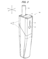
- FIG. 3 is an overall perspective view of the suction device 100 according to one embodiment of the present disclosure.
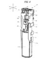
- FIG. 4 is a perspective view of the internal unit 10 as viewed from the front right side.
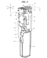
- FIG. 5 is a perspective view of the internal unit 10 as viewed from the front left side.
- FIG. 6 is an exploded perspective view of the internal unit 10.
- FIG. 7 is a cross-sectional perspective view of heater assembly 30.
- FIG. 8 is a cross-sectional view taken along line AA in FIG.
- the sensor unit 112A acquires various information related to the suction device 100A.
- the sensor unit 112A is configured with a pressure sensor such as a condenser microphone, a flow rate sensor, or a temperature sensor, and acquires values associated with suction by the user.
- the sensor unit 112A is configured with an input device such as a button or switch that accepts information input from the user.
- the notification unit 113A notifies the user of information.
- the information that the notification unit 113A notifies the user includes various information such as the SOC (State Of Charge) indicating the charging state of the power supply unit 111A, the pre-heating time for inhalation, and the period during which inhalation is possible.
- the notification unit 113A is composed of, for example, a light-emitting device that emits light, a display device that displays images, a sound output device that outputs sound, or a vibration device that vibrates.
- the liquid guide section 122 guides and holds the aerosol source, which is a liquid stored in the liquid storage section 123, from the liquid storage section 123.
- the liquid guide section 122 is, for example, a wick formed by twisting a fiber material such as glass fiber or a porous material such as porous ceramic. In this case, the aerosol source stored in the liquid storage section 123 is guided by the capillary effect of the wick.
- the flavor source 131 is a component for imparting flavor components to the aerosol.
- the flavor source 131 may contain tobacco-derived or non-tobacco-derived flavor components.
- the air flow path 180 is a flow path for air inhaled by the user.
- the air flow path 180 has a tubular structure with an air inlet hole 181, which is an entrance of air into the air flow path 180, and an air outlet hole 182, which is an exit of air from the air flow path 180, at both ends.
- the liquid guide section 122 is arranged on the upstream side (the side closer to the air inlet hole 181), and the flavor source 131 is arranged on the downstream side (the side closer to the air outlet hole 182).
- Each of the power supply unit 111B, the sensor unit 112B, the notification unit 113B, the memory unit 114B, the communication unit 115B, and the control unit 116B is substantially the same as the corresponding components included in the suction device 100A according to the first configuration example.
- the storage section 140 has an internal space 141 and holds the stick-shaped substrate 150 while storing a part of the stick-shaped substrate 150 in the internal space 141.
- the storage section 140 has an opening 142 that connects the internal space 141 to the outside, and stores the stick-shaped substrate 150 inserted into the internal space 141 through the opening 142.
- the storage section 140 is a cylindrical body with the opening 142 and the bottom 143 as the bottom surface, and defines a columnar internal space 141.
- An air flow path that supplies air to the internal space 141 is connected to the storage section 140.
- An air inlet hole which is an air inlet to the air flow path, is arranged, for example, on the side of the suction device 100.
- An air outlet hole which is an air outlet from the air flow path to the internal space 141, is arranged, for example, on the bottom 143.
- the stick-type substrate 150 includes a substrate portion 151 and a mouthpiece portion 152.
- the substrate portion 151 includes an aerosol source.
- the aerosol source includes a flavor component derived from tobacco or non-tobacco.
- the aerosol source may include a medicine.
- the aerosol source may be, for example, a liquid such as polyhydric alcohol such as glycerin and propylene glycol, and water, which includes a flavor component derived from tobacco or non-tobacco, or may be a solid containing a flavor component derived from tobacco or non-tobacco.
- the stick-type substrate 150 When the stick-type substrate 150 is held in the storage portion 140, at least a part of the substrate portion 151 is stored in the internal space 141, and at least a part of the mouthpiece portion 152 protrudes from the opening 142.
- the heating section 121B is configured in a film shape and is arranged to cover the outer periphery of the storage section 140.
- the heating section 121B generates heat, the substrate section 151 of the stick-shaped substrate 150 is heated from the outer periphery, and an aerosol is generated.
- the insulating section 144 prevents heat transfer from the heating section 121B to other components.
- the insulating section 144 is made of a vacuum insulating material or an aerogel insulating material.
- the heating section 121B may be configured in a blade shape and disposed so as to protrude from the bottom 143 of the storage section 140 into the internal space 141. In that case, the blade-shaped heating section 121B is inserted into the substrate section 151 of the stick-shaped substrate 150 and heats the substrate section 151 of the stick-shaped substrate 150 from the inside. As another example, the heating section 121B may be disposed so as to cover the bottom 143 of the storage section 140. Furthermore, the heating section 121B may be configured as a combination of two or more of a first heating section that covers the outer periphery of the storage section 140, a blade-shaped second heating section, and a third heating section that covers the bottom 143 of the storage section 140.
- the storage unit 140 may include an opening/closing mechanism, such as a hinge, that opens and closes a portion of the outer shell that forms the internal space 141. The storage unit 140 may then open and close the outer shell to accommodate the stick-shaped substrate 150 inserted into the internal space 141 while clamping it.
- the heating unit 121B may be provided at the clamping location in the storage unit 140, and may heat the stick-shaped substrate 150 while pressing it.
- the means for atomizing the aerosol source is not limited to heating by the heating unit 121B.
- the means for atomizing the aerosol source may be induction heating.
- the suction device 100B has at least an electromagnetic induction source such as a coil that generates a magnetic field, instead of the heating unit 121B.
- a susceptor that generates heat by induction heating may be provided in the suction device 100B, or may be included in the stick-shaped substrate 150.
- the suction device 100B may further include the heating unit 121A, the liquid guide unit 122, the liquid storage unit 123, and the air flow path 180 according to the first configuration example, and the air flow path 180 may supply air to the internal space 141.
- the mixed fluid of the aerosol and air generated by the heating unit 121A flows into the internal space 141 and is further mixed with the aerosol generated by the heating unit 121B, and reaches the user's oral cavity.
- suction device 100 an embodiment of a suction device (hereinafter, referred to as suction device 100) in which the configuration of the suction device disclosed herein is applied to the suction device 100B of the second configuration example described above will be described. Note that, although a specific description will be omitted, a part of the configuration of the suction device 100 described in detail below can also be applied to the suction device 100A of the first configuration example.
- [Overall configuration of the suction device] 3 is an overall perspective view of the suction device 100.
- the direction in which the stick-type substrate 150 is inserted into and removed from the suction device 100 is defined as the up-down direction
- the direction in which the shutter 23, which will be described later, slides and moves is defined as the front-rear direction
- the direction perpendicular to the up-down direction and the front-rear direction is defined as the left-right direction.
- the front is defined as Fr
- the rear is defined as Rr
- the left side is defined as L
- the right side is defined as R
- the top is defined as U
- the bottom is defined as D.
- the suction device 100 is preferably sized to fit in the hand, and has, for example, a rod shape.
- a user holds the suction device 100 in one hand with the fingertips in contact with the surface of the suction device 100.
- the shape of the suction device 100 is not limited to a rod shape, and can be any shape (for example, a rounded, approximately rectangular parallelepiped shape or an egg shape).
- the suction device 100 comprises an internal unit 10 (see Figures 4 to 6) and a case 20 that constitutes the exterior of the suction device 100.
- the case 20 has a lower case 21 and an upper case 22. A portion of the internal unit 10 is housed in the lower case 21, and the entire internal unit 10 is housed in the case 20 by placing the upper case 22 over the lower case 21 from above.
- the top surface of the suction device 100 is provided with an opening 27 (see Figures 4 to 6) through which the stick-shaped substrate 150 is inserted and removed, and a shutter 23 that can slide back and forth.
- the opening 27 is located at the rear side of the top surface of the suction device 100.
- the shutter 23 selectively takes an open state (front position) that opens the opening 27 to allow the stick-shaped substrate 150 to be inserted and removed, and a closed state (rear position) that positions the shutter 23 above the opening 27 to close the opening 27.
- the user opens the shutter 23.
- a shutter detection sensor 11 (see FIG. 4) is provided near the shutter 23.
- the shutter detection sensor 11 detects whether the shutter 23 is open or not.
- the shutter detection sensor 11 is an example of the sensor unit 112B of the suction device 100B in FIG. 2.
- a USB (Universal Serial Bus) port 26 (see FIG. 4) is provided on the top surface of the suction device 100, adjacent to the opening 27.
- the shutter 23 blocks the USB port 26.
- the USB port 26 is open.
- the USB port 26 is configured to be electrically connectable to an external power source (not shown) capable of supplying power for charging the power supply unit 111C (see FIG. 4).
- the USB port 26 is, for example, a receptacle into which a mating plug can be inserted.
- the USB port 26 is a USB Type-C shaped receptacle.
- the suction device 100 has an operation unit 24 and a light-emitting unit 25 on the front side.
- the operation unit 24 is disposed below the light-emitting unit 25. More specifically, the operation unit 24 and the light-emitting unit 25 are components of the internal unit 10 housed in the case 20, and are configured such that a portion of the operation unit 24 and the light-emitting unit 25 are exposed from an opening formed on the front side of the case 20.
- the light-emitting unit 25 is an example of the notification unit 113B of the suction device 100B in FIG. 2.
- the operation unit 24 is a button-type switch that can be operated by the user, and is an input device that accepts information input from the user.
- the operation unit 24 is connected to the main board 50 (see Figures 4 to 6) described below.
- the MCU (Micro Controller Unit) 1 (see Figures 4 to 6) or the heating unit 121C (see Figure 7) is started.
- the MCU 1 functions as the control unit 116B in the suction device 100B.
- the MCU 1 may also have an integrated function as the communication unit 115B in addition to the function as the control unit 116B in the suction device 100B.
- the MCU 1 may be composed of one IC or two or more ICs.
- the discharge control to the heating unit 121C and the charge control to the power supply unit 111C may be performed by one IC or by separate ICs.
- the light-emitting unit 25 is composed of light-emitting elements such as LEDs (Light Emitting Diodes).
- the light-emitting unit 25 has a plurality of LEDs 251 (see FIG. 6) provided on the main board 50, and a transparent cover 250 that covers the plurality of LEDs 251 and transmits light from the LEDs 251. A portion of the transparent cover 250 is exposed from an opening formed on the front surface of the case 20.
- the plurality of LEDs 251 are configured to be capable of emitting light in a plurality of colors including blue, yellow, and red.
- the number of light-emitting elements can be set arbitrarily, and for example, the light-emitting unit 25 may have only one light-emitting element.
- the light emitting unit 25 emits light in a predetermined light emission manner in response to a command from the MCU 1, and notifies the user of predetermined information.
- the light emission manner can be, for example, the light emission color, but is not limited to this, and can be, for example, the strength of the lighting intensity (in other words, brightness), or the lighting pattern (for example, blinking at a predetermined time interval), etc.
- the predetermined information is, for example, operational information indicating whether the power of the suction device 100 is on or not.
- Figure 4 is a perspective view of the internal unit 10 seen from the front right side
- Figure 5 is a perspective view of the internal unit 10 seen from the front left side
- Figure 6 is an exploded perspective view of the internal unit 10. Note that the internal unit 10 is the suction device 100 with the case 20 and shutter 23 removed.
- the internal unit 10 includes a chassis 40, a main board 50, a vibration device 60, a heater assembly 30, a power supply unit 111C, a power supply board 71, a peripheral FPC (Flexible Printed Circuits) 72, a sensor FPC 73, and various sensors.
- the power supply board 71 may be a flexible circuit board, a rigid board (described below), or a combination of a flexible board and a rigid board, but a flexible circuit board will be used as an example here.
- the chassis 40 has a power supply holding portion 41 that holds the power supply unit 111C, a board holding portion 42 that holds the main board 50, and a heater holding portion 43 that holds the heater assembly 30.
- the power supply holding portion 41 is located in the lower part of the chassis 40, and the board holding portion 42 and the heater holding portion 43 are located in the upper part of the chassis 40.
- the power supply holding section 41 has a cylindrical shape with a portion of the side cut out, in other words, a roughly semi-cylindrical shape.
- the power supply holding section 41 has a bottom wall section 401, a side wall section 402 having an arc shape and standing upward from the bottom wall section 401, and an upper wall section 403 provided at the upper end section of the side wall section 402.
- the power supply section 111C is disposed in a space surrounded by the bottom wall section 401, the side wall section 402, and the upper wall section 403.
- the board holding portion 42 is provided on a vertical wall portion 404 that stands upward from the upper wall portion 403 of the power supply holding portion 41.
- the board holding portion 42 is provided on one side (here, the front side) of the vertical wall portion 404 in the front-to-rear direction, and holds the main board 50.
- the heater holding portion 43 is provided on the opposite side (here, the rear side) of the vertical wall portion 404 from the substrate holding portion 42 in the front-rear direction.
- the heater holding portion 43 has a space surrounded by the vertical wall portion 404, a pair of left and right wall portions 405 extending in the front-rear direction from the vertical wall portion 404, and the upper surface of the upper wall portion 403 of the power supply holding portion 41, and the heater assembly 30 is disposed in this space.
- the main board 50 is a rigid board on which a plurality of electronic components (elements) are mounted on both sides.
- An MCU 1, an LED 251, a charging IC (Integrated Circuit), a step-up DC/DC converter, etc. are mounted on the main board 50.
- the main board 50 is held by the board holder 42 of the chassis 40 so that the element mounting surface faces the front-rear direction.
- FIG. 6 only the front surface 501 (here, the front surface) of the main board 50 is shown. Therefore, the charging IC and the step-up DC/DC converter mounted on the back surface 502 (here, the rear surface) are not shown.
- a power supply connection section 51 that is electrically connected to the power supply section 111C is provided in the lower region of the surface 501 of the main board 50.
- the power supply connection section 51 is electrically connected to the power supply section 111C via the power supply board 71.
- the power supply section 111C is a cylindrical lithium ion secondary battery, and is an example of the power supply section 111B of the suction device 100B in FIG. 2.
- the power supply unit 111C is provided with a positive electrode tab 111a and a negative electrode tab 111b.
- the power supply unit 111C is arranged in the power supply holding portion 41 of the chassis 40 with the positive electrode tab 111a and the negative electrode tab 111b arranged in front.
- the power supply board 71 is arranged in front of the power supply unit 111C and the main board 50 and extends in the vertical direction.
- the power supply board 71 is connected to the positive electrode tab 111a and the negative electrode tab 111b of the power supply unit 111C, and is also connected to the power supply connection portion 51 of the main board 50.
- the power of the power supply unit 111C is transmitted to the main board 50 through the conductive track formed on the power supply board 71 and supplied to each electronic component.
- the power supply board 71 is also provided with a power supply temperature sensor 16.
- the power supply temperature sensor 16 is a sensor that detects the temperature of the power supply unit 111C.
- the power supply temperature sensor 16 is, for example, a thermistor.
- the power supply temperature sensor 16 is an example of the sensor portion 112B of the suction device 100B in FIG. 2.
- a USB port 26 is provided in the upper region of the back surface 502 of the main board 50.
- the USB port 26 is electrically connected to a charging IC (not shown) by wiring formed on the main board 50.
- the rear surface 502 of the main board 50 is provided with a heater connection section in addition to a charging IC and a boost DC/DC converter (not shown).
- the charging IC performs charging control to supply (charge) the power input from the USB port 26 to the power supply section 111C.
- the boost DC/DC converter boosts the power supplied from the power supply section 111C to generate power to be supplied to the heating section 121C (see FIG. 7).
- the heater connection portion is connected to the board connection portion 121a extending from below the heater assembly 30, and supplies power to the heating portion 121C of the heater assembly 30. As a result, power is supplied from the power supply portion 111C via the main board 50 to the heating portion 121C of the heater assembly 30.
- the vibration device 60 is composed of a vibration element such as a vibration motor. As shown in FIG. 6, the vibration device 60 is disposed in the power supply holding portion 41 of the chassis 40 between the upper surface of the power supply portion 111C and the upper wall portion 403. The lead wire 61 of the vibration device 60 is connected to the peripheral FPC 72.
- the vibration device 60 vibrates in a predetermined vibration mode in response to a command from the MCU 1 to notify the user of predetermined information. For example, when the heating of the stick-type substrate 150 starts or ends, the vibration device 60 vibrates in a predetermined vibration mode to notify the user of the start or end of heating.
- the vibration device 60 is an example of the notification portion 113B of the suction device 100B in FIG. 2.
- FIG. 7 is a cross-sectional perspective view of heater assembly 30.
- the heater assembly 30 includes a heating section 121C, a housing section 140C, and a heat insulating section 144C.
- the heating section 121C is, for example, a film heater, and is wound around the outer periphery of the housing section 140C.
- the heating section 121C and the board connection section 121a may be formed of a single heater FPC.
- the heater assembly 30 is also provided with a stick guide 31.
- the stick guide 31 is provided on the upper part of the heater assembly 30 and guides the insertion and removal of the stick-shaped substrate 150 into the storage section 140C.
- the stick guide 31 is a cylindrical member that has an opening 27 and constitutes part of the storage section 140C.
- the heater assembly 30 is also provided with a heater temperature sensor 15 capable of detecting the temperature of the heating section 121C. More specifically, the heater temperature sensor 15 is provided between the heating section 121C and the insulating section 144C, in contact with or in close proximity to the heating section 121C.
- the heater temperature sensor 15 is, for example, a thermistor.
- the sensor FPC 73 is disposed between the standing wall portion 404 of the heater holding portion 43 and the heater assembly 30.
- the sensor FPC 73 is equipped with a stick detection sensor 12, a suction sensor 13, and a case temperature sensor 14.
- the stick detection sensor 12, the suction sensor 13, and the case temperature sensor 14 are an example of the sensor unit 112B of the suction device 100B in FIG.
- the stick detection sensor 12 is a sensor capable of detecting the stick-shaped substrate 150 housed in the housing section 140C.
- the stick detection sensor 12 is an optical sensor capable of detecting the stick-shaped substrate 150 based on the amount of reflected light of light irradiated onto the housing section 140C.
- the amount of light is a concept that includes luminous flux, illuminance, luminous flux emittance, luminous intensity, brightness, etc.
- the optical sensor is, for example, an IR (Infrared Rays) sensor.
- the suction sensor 13 is a sensor that detects the user's puffing action (inhalation action).
- the suction sensor 13 is composed of, for example, a condenser microphone or a pressure sensor.
- the suction sensor 13 is provided near the stick guide 31 on the sensor FPC 73.
- the case temperature sensor 14 is a sensor that detects the temperature of the case 20.
- the case temperature sensor 14 is, for example, a thermistor.
- the case temperature sensor 14 is arranged adjacent to the inner surface of the case 20 on the sensor FPC 73.
- the sensor FPC 73 is also provided with a heater temperature sensor connection 731 that connects to the heater temperature sensor 15 of the heater assembly 30.
- the heater temperature sensor connection 731 is provided on the lower part of the sensor FPC 73. More specifically, a lead wire 15a is connected to the heater temperature sensor 15, and the heater temperature sensor connection 731 connects to the lead wire 15a extending from below the heater assembly 30.
- the stick detection sensor 12, suction sensor 13, case temperature sensor 14, and heater temperature sensor connection part 731 are connected to the board connection part 730 via conductive tracks formed on the sensor FPC 73.
- the board connection part 730 is connected to the sensor FPC connection part 55 provided in the central region of the surface 501 of the main board 50. This allows the detection results of each sensor to be output to the MCU 1 mounted on the main board 50, etc.
- the MCU1 starts heating the heating unit 121C.
- aerosol is supplied into the user's mouth from the aerosol source of the stick-shaped substrate 150 heated by the heating unit 121C.
- the suction sensor 13 detects the number of suctions, and the MCU1 stops heating after a predetermined number of suctions or after a predetermined time has elapsed.
- the suction device 100 While the suction device 100 is heating, the case temperature sensor 14, heater temperature sensor 15, and power supply temperature sensor 16 detect the respective temperatures, and if abnormal heating is determined, the MCU1 stops or suppresses heating of the heating unit 121C.
- the user can operate the operation unit 24 to, for example, check the SOC of the power supply unit 111C.
- the light-emitting unit 25 (LED 251) and the vibration device 60 notify the user of various information such as the SOC of the power supply unit 111C, error indications, etc. If the SOC of the power supply unit 111C decreases, the user can connect an external power source to the USB port 26 to charge the power supply unit 111C.
- the stick detection sensor 12 is an optical sensor that irradiates light to the storage section 140C and detects the amount of light reflected from the storage section 140C.
- the MCU 1 is configured to be able to detect whether or not the stick-shaped substrate 150 is stored in the storage section 140C based on the amount of reflected light detected by the stick detection sensor 12.
- the light that the stick detection sensor 12 irradiates and receives is, for example, near-infrared light, and in this case, the stick detection sensor 12 is an IR sensor.
- the stick detection sensor 12 is assumed to detect "brightness" as an example of the amount of light.
- FIG. 8 is a cross-sectional view taken along line A-A in FIG. 5, and shows the structure around the sensor FPC 73, the stick detection sensor 12, and the stick guide 31 (housing section 140C).
- the sensor FPC 73 is a flexible member, and is arranged around the housing section 140C.
- the stick detection sensor 12 is provided on the sensor FPC 73. This makes it easier to arrange the stick detection sensor 12 around the housing section 140C, compared to when the stick detection sensor 12 is provided on the rigid main board 50. This allows greater freedom in terms of arrangement, and thus makes it possible to miniaturize the suction device 100.
- the stick detection sensor 12 is positioned at a predetermined distance from the stick guide 31 to reduce the effect of heat from the stick guide 31 (housing section 140C).
- a light-transmitting filter 311 is provided on a portion of the wall section that divides the housing section 140C in the stick guide 31, and the sensor FPC 73 is positioned around the housing section 140C so that the stick detection sensor 12 faces the light-transmitting filter 311 at a predetermined distance.
- the portions of the stick guide 31 where the light-transmitting filter 311 is not provided are configured to be non-light-transmitting.
- the stick detection sensor 12 irradiates light to the storage section 140C through the transmission filter 311 and receives the reflected light.
- the storage section 140C hereinafter also referred to as the storage state
- the light irradiated from the stick detection sensor 12 is reflected by the surface of the stick-shaped substrate 150 immediately after passing through the transmission filter 311.
- the stick detection sensor 12 receives the reflected light reflected by the surface of the stick-shaped substrate 150.
- the light irradiated from the stick detection sensor 12 passes through the transmission filter 311, travels inside the storage section 140C, and is reflected by the inner wall of the storage section 140C.
- the stick detection sensor 12 receives the reflected light reflected by the inner wall of the storage section 140C.
- the MCU 1 Based on this difference in brightness between the housed state and the unhoused state, the MCU 1 detects the stick-shaped substrate 150. Specifically, as shown in FIG. 10, the MCU 1 detects the stick-shaped substrate 150 when the brightness of the reflected light detected by the stick detection sensor 12 is equal to or greater than a predetermined value L1. On the other hand, the MCU 1 does not detect the stick-shaped substrate 150 when the brightness of the reflected light detected by the stick detection sensor 12 is less than the predetermined value L1.
- two stick detection sensors 12 and two transmission filters 311 are provided.
- the MCU 1 can be configured not to detect the stick-shaped substrate 150 unless the detection results of both stick detection sensors 12 indicate that the stick-shaped substrate 150 is housed.
- the suction device 100 is activated, for example, when the shutter 23 is opened.
- the MCU 1 is activated when the shutter detection sensor 11 detects that the shutter 23 is opened.
- the operation of the heating unit 121C and the like become possible.
- the shutter detection sensor 11 is composed of, for example, a magnet provided on the shutter 23 and a Hall IC (Integrated Circuit) provided on the upper end of the main board 50.
- the MCU 1 may be activated in response to pressing the operation unit 24.
- the automatic heating mode is a mode in which the operation of the heating section 121C is automatically started in response to the stick-shaped substrate 150 being accommodated in the accommodation section 140C.
- the automatic heating mode for example, in response to the shutter 23 being opened, the stick detection sensor 12 starts emitting and receiving light, and detects the amount of reflected light.
- the MCU 1 detects the stick-shaped substrate 150 based on the detection result of the stick detection sensor 12, and then starts heating the stick-shaped substrate 150.
- the manual heating mode is a mode in which the operation of the heating unit 121C is started in response to a heating request from the user.
- the MCU 1 does not automatically start heating the stick-shaped substrate 150 even if it detects the stick-shaped substrate 150.
- the MCU 1 starts heating the stick-shaped substrate 150 in response to a heating request from the user.
- a heating request from the user is, for example, pressing the operation unit 24 or a suction operation on the suction device 100.
- the user selects either the automatic heating mode or the manual heating mode.
- the mode selection is performed, for example, on a user terminal (such as a smartphone), and the MCU1 receives instruction information from the user terminal via the communication unit 115B and sets the mode selected by the user.
- the MCU1 operates the heating portion 121C based on a stick heating profile for heating the stick-shaped substrate 150.
- the stick heating profile is information that specifies the time series transition of a target temperature, which is a target value for the temperature of the heating portion 121C, and is information for heating the stick-shaped substrate 150.
- the stick heating profile is stored in advance in, for example, a ROM.
- the MCU1 generates an aerosol from the stick-shaped substrate 150 by controlling the temperature of the heating portion 121C based on the stick heating profile.
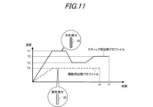
- the solid line in FIG. 11 shows an example of a heating profile for a stick.
- the temperature of the heating unit 121C is raised to a maximum temperature T1 when heating control starts, then lowered to T2, and then raised again to T3.
- T1 a maximum temperature
- T2 a temperature of the heating unit 121C
- the MCU 1 controls the temperature of the heating section 121C based on the deviation between a target temperature corresponding to the time elapsed since the start of heating control and the actual temperature of the heating section 121C (hereinafter also referred to as the "actual temperature"). More specifically, at this time, the MCU 1 controls the temperature of the heating section 121C so that the time series progression of the actual temperature of the heating section 121C becomes similar to the time series progression of the target temperature defined in the heating profile for sticks. Note that the heating control of the storage section 140C based on the heating profile for cleaning, which will be described later, is also performed in a similar manner.
- the stick heating profile is typically designed to optimize the flavor experienced by the user when the user inhales the aerosol generated from the stick-shaped substrate 150. Therefore, by controlling the temperature of the heating section 121C based on the stick heating profile, the flavor experienced by the user can be optimized, providing the user with a high-quality smoking experience.
- the storage section 140C may become dirty during use of the inhalation device 100.
- a part of the aerosol source of the stick-type substrate 150 e.g., tobacco leaves
- a part of the aerosol generated by heating the stick-type substrate 150 may become liquid and adhere to the storage section 140C.
- the storage section 140C is dirty, the quality of the flavor experienced by the user may be reduced, so it is desirable for the user to regularly clean the storage section 140C.
- the storage section 140C is cleaned, for example, by inserting a cleaning tool (e.g., a cotton swab) coated with a cleaning agent (e.g., a liquid substance such as alcohol or water) into the storage section 140C.
- a cleaning tool e.g., a cotton swab
- a cleaning agent e.g., a liquid substance such as alcohol or water
- the MCU1 when the stick-shaped substrate 150 is not housed in the housing portion 140C, the MCU1 operates the heating portion 121C based on a cleaning heating profile for heating the housing portion 140C in which the stick-shaped substrate 150 is not housed.
- the cleaning heating profile is information that specifies the time series progression of the target temperature, which is the target value for the temperature of the heating portion 121C, and is information for cleaning the inside of the housing portion 140C.
- the cleaning heating profile is stored in advance in, for example, a ROM.
- the cleaning heating profile is a heating profile that is different from the stick heating profile, and has different information such as the target temperature and operation time, as described below.
- the MCU1 can evaporate and remove the cleaning agent adhering to the storage section 140C in which the stick-shaped substrate 150 is not stored, by controlling the temperature of the heating section 121C based on the cleaning heating profile. Therefore, even if the user has just cleaned the storage section 140C with a cleaning tool, the MCU1 can heat the storage section 140C based on the cleaning heating profile, so that the inhalation device 100 can provide the user with a high-quality smoking experience without compromising the quality of the flavor. This can improve the convenience of using the inhalation device 100.
- the heating based on the cleaning heating profile not only can the cleaning agent be removed, but also dirt that has adhered to the storage section 140C during use of the suction device 100 as described above can be removed.
- the heating based on the cleaning heating profile the liquid present in the storage section 140C is evaporated, so that a portion of the aerosol source (e.g., tobacco leaves) that was adhered to the storage section 140C by the liquid no longer adheres to the storage section 140C. Therefore, the user can easily remove a portion of the aerosol source from the storage section 140C, for example, by pointing the opening 27 downward.
- the aerosol source e.g., tobacco leaves
- the MCU1 operates the heating section 121C based on the cleaning heating profile.
- the heating request from the user in this case is, for example, pressing the operation section 24.
- the MCU1 may operate the heating unit 121C based on the cleaning heating profile, provided that the manual heating mode is selected in addition to the above conditions.
- the stick detection sensor 12 when the manual heating mode is selected and there is a heating request from the user, the stick detection sensor 12 starts operating (emitting and receiving light). When there is a heating request from the user and the stick-shaped substrate 150 is not detected based on the detection result of the stick detection sensor 12, the MCU 1 operates the heating unit 121C based on the cleaning heating profile. By starting the operation of the stick detection sensor 12 when there is a heating request from the user, it is possible to reduce power consumption compared to when the stick detection sensor 12 operates all the time. Note that the timing at which the stick detection sensor 12 starts operating in the manual heating mode is not limited to this. As in the automatic heating mode, in the manual heating mode, the stick detection sensor 12 may also be configured to start operating in response to the shutter 23 being opened.
- the cleaning heating profile (dashed line in FIG. 11) will be described in comparison with the stick heating profile.
- the temperature of the heating unit 121C is raised to a maximum temperature T4 when heating control is started, and then maintained at the temperature T4.
- the heating control is ended.
- the target temperature of the heating section 121C in the cleaning heating profile is set lower than the target temperature of the heating section 121C in the stick heating profile.
- the maximum target temperature T1 in the stick heating profile is set to approximately 300°C
- the maximum target temperature T4 in the cleaning heating profile is approximately 100°C to 200°C.
- the maximum target temperature T4 in the cleaning heating profile is set to a temperature that can evaporate the moisture in the storage section 140C, for example, above the boiling point of water.
- the stick heating profile and the cleaning heating profile contain information on the operating time for operating the heating unit 121C, and the operating time t2 of the cleaning heating profile is set shorter than the operating time t1 of the stick heating profile.
- the operating time t2 of the cleaning heating profile need only be long enough to evaporate the moisture in the storage unit 140C. By setting the operating time in this manner, excessive heating of the storage unit 140C in which the stick-shaped substrate 150 is not stored is prevented. Also, power consumption can be reduced.
- the light-emitting unit 25 notifies the user that the heating unit 121C is in operation. Specifically, the light-emitting unit 25 emits light in a predetermined light-emitting manner when the heating unit 121C is in operation with the stick-shaped substrate 150 housed in the housing unit 140C (i.e., the housed state), and when the heating unit 121C is in operation with the stick-shaped substrate 150 not housed in the housing unit 140C (i.e., the unhoused state).
- This notification allows the user to easily visually know that the heating unit 121C is in operation.
- the user can check the light emitted by the light-emitting unit 25 and be careful not to bring their fingers close to the opening 27, for example.
- the light-emitting unit 25 may emit light in different light emission modes when the heating unit 121C is operating in a housed state and when the heating unit 121C is operating in a non-housed state. For example, as shown in FIG. 11, the light emission color of the LED 251 is changed depending on whether the light emission mode is during heating control based on a stick heating profile or during heating control based on a cleaning heating profile.
- the light emission mode may also be differentiated by changing the number of LEDs 251 that emit light out of the multiple LEDs 251.
- the notification by the notification unit 113B is not limited to light emission by the light emitting unit 25, and may be, for example, vibration by the vibration device 60.
- the vibration device 60 may vibrate while the heating unit 121C is operating to notify the user that the heating unit 121C is operating.
- the vibration device 60 may vibrate in a different manner when the heating unit 121C is operating in a housed state than when the heating unit 121C is operating in an unhoused state.
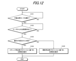
- the MCU1 determines whether or not the manual heating mode is selected (step S101). If the manual heating mode is not selected (step S101: NO), the MCU1 repeatedly monitors step S101 until the manual heating mode is selected.
- step S101 determines whether or not there is a heating request from the user (step S102). If there is no heating request from the user (step S102: NO), the MCU1 repeatedly monitors step S102 until there is a heating request from the user.
- step S102 When there is a heating request from the user (step S102: YES), the MCU1 determines whether or not the stick-shaped substrate 150 is contained in the storage section 140C (step S103). Specifically, when there is a heating request from the user, the stick detection sensor 12 starts operating, and the MCU1 obtains the detection result from the stick detection sensor 12 and determines whether or not the stick-shaped substrate 150 is contained in the storage section 140C.
- step S103 When the stick-shaped substrate 150 is contained in the container 140C (step S103: YES), the MCU1 operates the heating unit 121C based on the stick heating profile (step S104). This starts heating the stick-shaped substrate 150, and an aerosol is generated.
- step S103 when the stick-shaped substrate 150 is not contained in the storage unit 140C (step S103: NO), the MCU1 operates the heating unit 121C based on the cleaning heating profile (step S105). This allows the liquid substance in the storage unit 140C to be evaporated and removed by the heating by the heating unit 121C.
- the MCU1 operates the heating unit 121C based on the cleaning heating profile on the assumption that the manual heating mode is selected (i.e., YES in step S101), but this is not limited to the above.
- the heating unit 121C may be configured to operate based on the cleaning heating profile.
- the MCU1 may operate the heating unit 121C based on the cleaning heating profile when there is a heating request from the user (e.g., pressing the operation unit 24).
- the MCU 1 when the luminance of the reflected light is less than the predetermined value L1, the MCU 1 does not detect the stick-shaped substrate 150 and operates the heating unit 121C based on the heating profile for cleaning.
- This modified example differs from the embodiment described above in that the MCU 1 may not operate the heating unit 121C even when the luminance of the reflected light is less than the predetermined value L1.
- the brightness of the reflected light may be lower than when there is little cleaning agent or dirt. This is thought to be because when the light emitted from the stick detection sensor 12 reflects off the inner wall of the storage section 140C, it is scattered by the cleaning agent or dirt, reducing the amount of light that returns to the stick detection sensor 12.
- the MCU1 when it is determined that there is little cleaning agent or dirt in the storage section 140C based on the brightness of the reflected light, the MCU1 does not operate the heating section 121C.
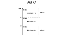
- the region of the luminance of the reflected light detected by the stick detection sensor 12 will be described.
- the MCU1 detects the stick-shaped substrate 150.
- the MCU1 does not detect the stick-shaped substrate 150.
- L2 is a value smaller than L1.
- the MCU1 detects the stick-shaped substrate 150 and operates the heating unit 121C based on the stick heating profile as in the embodiment described above.
- the MCU1 does not detect the stick-shaped substrate 150 and does not operate the heating unit 121C. As a result, when it is determined that there is little cleaning agent or dirt in the storage unit 140C, the MCU1 does not operate the heating unit 121C, thereby reducing power consumption. Note that when a heating request from a user is set as a condition for heating control, the MCU1 will not operate the heating unit 121C despite the heating request from the user, so the user may be notified that the heating unit 121C will not be operated via a communication unit such as the light-emitting unit 25 or the vibration device 60.
- the MCU1 does not detect the stick-shaped substrate 150 and operates the heating unit 121C based on the cleaning heating profile.
- the heating unit 121C is operated based on the cleaning heating profile, and the liquid substance in the storage unit 140C can be evaporated and removed.
- the stick detection sensor 12 starts operating and detects the brightness of the reflected light in response to the shutter 23 being opened.
- the MCU 1 may prompt the user via a communication unit such as the light-emitting unit 25 or the vibration device 60 to perform heating based on the cleaning heating profile. This allows the user who has received the notification to press the operation unit 24, for example, to cause the MCU 1 to execute heating control based on the cleaning heating profile.
- the MCU 1 may operate the heating unit 121C based on the cleaning heating profile instead of prompting the user to perform heating based on the cleaning heating profile.
- the control method of the suction device 100 described in the above-mentioned embodiment and modified example can be realized by executing a prepared program on a computer (processor).
- This program is stored in a computer-readable storage medium and is executed by reading it from the storage medium.
- this program may be provided in a form stored in a non-transitory storage medium such as a flash memory, or may be provided via a network such as the Internet.
- the computer that executes this program may be, for example, one included in the suction device 100 (e.g., MCU 1), but is not limited to this, and may also be one included in another device that can communicate with the suction device 100 (e.g., a smartphone or a server device).
- an optical sensor is shown as an example of the stick detection sensor 12, but this is not limited thereto.
- the stick detection sensor 12 may be a pressure sensor that detects pressure fluctuations in the storage section 140C accompanying the insertion and removal of the stick-shaped substrate 150.
- the MCU1 detects the stick-shaped substrate 150 based on the pressure fluctuations detected by the pressure sensor.
- the stick detection sensor 12 may be an identification information reader capable of reading the identification information of the stick-shaped substrate 150. In this case, the MCU1 detects the stick-shaped substrate 150 based on the reading result by the identification information reader.
- the stick detection sensor 12 may be a mechanical switch provided near the storage section 140C (for example, the bottom surface of the storage section 140C) and pressed by the stick-shaped substrate 150.
- the MCU1 detects the stick-shaped substrate 150 when the switch is pressed.
- the MCU 1 may detect the stick-shaped substrate 150 based on a change in the characteristics of the circuit of the suction device 100 (e.g., a change in inductance) caused by the insertion of the stick-shaped substrate 150.
- An inhalation device (inhalation device 100, 100A, 100B) that generates an aerosol from a substrate (stick-type substrate 150) having an aerosol source, A storage section (storage section 140, 140C) in which the base material is stored; A heating unit (heating units 121A to 121C) for heating the storage unit; A control unit (control units 116A, 116B, MCU1) that controls the heating unit based on heating information that specifies a time series transition of a target temperature that is a target value of the temperature of the heating unit, The heating information includes first heating information (a stick heating profile) for heating the substrate and second heating information (a cleaning heating profile) different from the first heating information; The control unit is When the base material is accommodated in the accommodation unit, operating the heating unit based on the first heating information; When the base material is not contained in the containing section, the heating section is operated based on the second heating information. Suction device.
- Dirty parts may become dirty when the inhalation device is used.
- a user cleans the storage unit with a liquid such as alcohol or water to remove dirt
- the inside of the storage unit becomes wet immediately after cleaning.
- the control unit operates the heating unit based on second heating information that is different from the first heating information for heating the substrate. This allows the liquid such as alcohol or water used for cleaning to be evaporated and removed, so that the user does not need to wait for the inside of the storage unit to dry naturally immediately after cleaning, and can have a high-quality smoking experience even immediately after cleaning. This improves the convenience of using the inhalation device.
- the target temperature of the second heating information is lower than the target temperature of the first heating information. Suction device.
- the moisture in the storage section can be evaporated by heating the storage section based on the second heating information.
- the suction device according to any one of (1) to (3),
- the first heating information and the second heating information each include an operation time for operating the heating unit,
- the operating time of the second heating information is shorter than the operating time of the first heating information.
- the suction device when there is a heating request from a user and the base material is not contained in the containing unit, operates the heating unit based on the second heating information. Suction device.
- heating control based on the second heating information can be executed based on the user's will.
- the suction device is a first mode (automatic heating mode) in which the operation of the heating unit is automatically started in response to the substrate being accommodated in the accommodation unit, and a second mode (manual heating mode) in which the operation of the heating unit is started in response to a heating request from the user, when the second mode is selected, when there is a heating request from the user and the substrate is not accommodated in the accommodation unit, operating the heating unit based on the second heating information.
- the operation of the heating unit can be selectively switched between the first mode and the second mode, the user can set the heating operation mode according to his/her desire.
- the heating unit can be operated based on the second heating information.
- the suction device according to any one of (1) to (6), An optical sensor (stick detection sensor 12) that irradiates light onto the storage section and detects the amount of light reflected from the storage section,
- the control unit is configured to detect the base material based on the amount of reflected light. Suction device.
- the suction device is When the amount of light is included in a first region, the substrate is detected, and the heating unit is operated based on the first heating information; When the amount of light is included in a second region different from the first region, the substrate is not detected and the heating unit is not operated; when the amount of light is included in a third region different from the first region and the second region, the substrate is not detected, and the heating unit is operated based on the second heating information. Suction device.
- the heating unit when heating based on the second heating information is not required, the heating unit is not operated, thereby reducing power consumption.
- suction device (9) The suction device according to (7) or (8), A flexible member (sensor FPC 73) is disposed around the housing portion and is electrically connected to the control portion. The optical sensor is provided on the flexible member. Suction device.
- the degree of freedom in arranging the optical sensor around the housing portion is increased compared to, for example, providing the optical sensor on a rigid substrate.
- a light transmitting member capable of transmitting light is provided on a part of a wall portion that divides the storage portion, The flexible member is disposed around the housing portion such that the optical sensor faces the transparent member at a predetermined distance. Suction device.
- the optical sensor faces the transparent member at a predetermined distance, so that the effect of heat from the housing on the optical sensor can be reduced.
- the suction device according to any one of (1) to (10),
- the heating device further includes a notification unit (light-emitting unit 25, vibration device 60) that notifies a user that the heating unit is operating.
- the notification unit notifies the user that the heating unit is operating when the substrate is not contained in the container unit and the heating unit is operating. Suction device.
- the user can easily understand that the heating unit is operating when the substrate is not contained in the container, and can take care not to place, for example, fingers near the container.
- the suction device is when the heating unit is operating with the substrate accommodated in the accommodation unit, notifying the user in a first notification manner that the heating unit is operating; When the heating unit is operating in a state in which the base material is not contained in the container unit, the user is notified that the heating unit is operating in a second notification manner different from the first notification manner. Suction device.
- the suction device includes a light-emitting unit (light-emitting unit 25) that notifies the user by emitting light,
- the first notification mode and the second notification mode have different light emission modes. Suction device.
- the user can easily visually determine whether heating control is being performed based on the first heating information or based on the second heating information.
- a control method executed by a computer for controlling the operation of an inhalation device (inhalation device 100, 100A, 100B) that generates an aerosol from a substrate (stick-type substrate 150) having an aerosol source, comprising:
- the suction device is A storage section (storage section 140, 140C) in which the base material is stored;
- a heating unit (heating units 121A to 121C) for heating the storage unit, the computer is configured to be able to control the heating unit based on heating information that defines a time series transition of a target temperature, which is a target value of the temperature of the heating unit;
- the heating information includes first heating information (a stick heating profile) for heating the substrate, and second heating information (a cleaning heating profile) different from the first heating information;
- the computer includes: When the base material is accommodated in the accommodation unit, the heating unit is operated based on the first heating information; When the base material is not contained in the containing section, the heating section is operated based on the second heating information.
- Dirty parts may become dirty when the inhalation device is used.
- a user cleans the storage part using a liquid such as alcohol or water to remove dirt
- the inside of the storage part becomes wet immediately after cleaning.
- the computer operates the heating part based on second heating information different from the first heating information for heating the substrate. This allows the liquid such as alcohol or water used for cleaning to be evaporated and removed, so that the user does not need to wait for the inside of the storage part to dry naturally immediately after cleaning, and can have a high-quality smoking experience even immediately after cleaning. This improves the convenience of using the inhalation device.
- the suction device is A storage section (storage section 140C) in which the base material is stored;
- a heating unit (heating units 121A to 121C) for heating the storage unit, the computer is configured to be able to control the heating unit based on heating information that defines a time series transition of a target temperature, which is a target value of the temperature of the heating unit;
- the heating information includes first heating information (a stick heating profile) for heating the substrate, and second heating information (a cleaning heating profile) different from the first heating information;
- the computer includes: When the base material is accommodated in the accommodation unit, the heating unit is operated based on the first heating information; When the base material is not contained in the containing section, the heating section is operated based on
- Dirty parts may become dirty when the inhalation device is used.
- a user cleans the storage part using a liquid such as alcohol or water to remove dirt
- the inside of the storage part becomes wet immediately after cleaning.
- the computer operates the heating part based on second heating information different from the first heating information for heating the substrate. This allows the liquid such as alcohol or water used for cleaning to be evaporated and removed, so that the user does not need to wait for the inside of the storage part to dry naturally immediately after cleaning, and can have a high-quality smoking experience even immediately after cleaning. This improves the convenience of using the inhalation device.
- a substrate having an aerosol source (a stick-type substrate 150);
- a suction system comprising a suction device (suction device 100, 100A, 100B) according to any one of (1) to (13).
- Dirty parts may become dirty when the inhalation device is used.
- a user cleans the storage unit with a liquid such as alcohol or water to remove dirt
- the inside of the storage unit becomes wet immediately after cleaning.
- the control unit operates the heating unit based on second heating information that is different from the first heating information for heating the substrate. This allows the liquid such as alcohol or water used for cleaning to be evaporated and removed, so that the user does not need to wait for the inside of the storage unit to dry naturally immediately after cleaning, and can have a high-quality smoking experience even immediately after cleaning. This improves the convenience of using the inhalation device.
- the suction device according to (13), The first notification mode and the second notification mode have different light emission colors of the light-emitting unit. Suction device.
- the user can easily know whether heating control is being performed based on the first heating information or the second heating information by checking the emitted color.
- the suction device according to (13),
- the light emitting unit has a plurality of light emitting elements (LEDs 251),
- the first notification mode and the second notification mode have different numbers of light-emitting elements that emit light.
- Suction device has a plurality of light emitting elements (LEDs 251),
- the first notification mode and the second notification mode have different numbers of light-emitting elements that emit light. Suction device.
- the user can easily determine whether heating control is being performed based on the first heating information or the second heating information by checking the number of light-emitting elements that are emitting light.
Landscapes
- Engineering & Computer Science (AREA)
- Human Computer Interaction (AREA)
- Infusion, Injection, And Reservoir Apparatuses (AREA)
- Surgical Instruments (AREA)
- Catching Or Destruction (AREA)
Priority Applications (5)
| Application Number | Priority Date | Filing Date | Title |
|---|---|---|---|
| PCT/JP2022/046464 WO2024127647A1 (ja) | 2022-12-16 | 2022-12-16 | 吸引装置、制御方法、及びプログラム |
| CN202280102574.2A CN120302907A (zh) | 2022-12-16 | 2022-12-16 | 吸入装置、控制方法和程序 |
| JP2024564122A JPWO2024127647A1 (https=) | 2022-12-16 | 2022-12-16 | |
| EP22968556.5A EP4635340A1 (en) | 2022-12-16 | 2022-12-16 | Inhalation device, control method, and program |
| KR1020257019829A KR20250108717A (ko) | 2022-12-16 | 2022-12-16 | 흡입 장치, 제어 방법 및 프로그램 |
Applications Claiming Priority (1)
| Application Number | Priority Date | Filing Date | Title |
|---|---|---|---|
| PCT/JP2022/046464 WO2024127647A1 (ja) | 2022-12-16 | 2022-12-16 | 吸引装置、制御方法、及びプログラム |
Publications (1)
| Publication Number | Publication Date |
|---|---|
| WO2024127647A1 true WO2024127647A1 (ja) | 2024-06-20 |
Family
ID=91484599
Family Applications (1)
| Application Number | Title | Priority Date | Filing Date |
|---|---|---|---|
| PCT/JP2022/046464 Ceased WO2024127647A1 (ja) | 2022-12-16 | 2022-12-16 | 吸引装置、制御方法、及びプログラム |
Country Status (5)
| Country | Link |
|---|---|
| EP (1) | EP4635340A1 (https=) |
| JP (1) | JPWO2024127647A1 (https=) |
| KR (1) | KR20250108717A (https=) |
| CN (1) | CN120302907A (https=) |
| WO (1) | WO2024127647A1 (https=) |
Citations (5)
| Publication number | Priority date | Publication date | Assignee | Title |
|---|---|---|---|---|
| JP2015508287A (ja) * | 2011-12-30 | 2015-03-19 | フィリップ・モーリス・プロダクツ・ソシエテ・アノニム | エアロゾル発生装置の加熱要素を清掃する方法及び装置 |
| CN112841748A (zh) * | 2021-04-14 | 2021-05-28 | 深圳市讴可电子科技有限公司 | 一种用于电子烟的控制方法及电子烟 |
| WO2021148361A1 (en) * | 2020-01-21 | 2021-07-29 | Jt International Sa | Electronic cigarette |
| JP2022524729A (ja) * | 2019-03-22 | 2022-05-10 | フィリップ・モーリス・プロダクツ・ソシエテ・アノニム | 残留物検出器を備えるエアロゾル発生装置およびシステム |
| JP2022526322A (ja) * | 2019-03-22 | 2022-05-24 | ネルディア リミテッド | 喫煙代用システム |
Family Cites Families (1)
| Publication number | Priority date | Publication date | Assignee | Title |
|---|---|---|---|---|
| EP2201850A1 (en) | 2008-12-24 | 2010-06-30 | Philip Morris Products S.A. | An article including identification information for use in an electrically heated smoking system |
-
2022
- 2022-12-16 KR KR1020257019829A patent/KR20250108717A/ko active Pending
- 2022-12-16 CN CN202280102574.2A patent/CN120302907A/zh active Pending
- 2022-12-16 EP EP22968556.5A patent/EP4635340A1/en active Pending
- 2022-12-16 WO PCT/JP2022/046464 patent/WO2024127647A1/ja not_active Ceased
- 2022-12-16 JP JP2024564122A patent/JPWO2024127647A1/ja active Pending
Patent Citations (5)
| Publication number | Priority date | Publication date | Assignee | Title |
|---|---|---|---|---|
| JP2015508287A (ja) * | 2011-12-30 | 2015-03-19 | フィリップ・モーリス・プロダクツ・ソシエテ・アノニム | エアロゾル発生装置の加熱要素を清掃する方法及び装置 |
| JP2022524729A (ja) * | 2019-03-22 | 2022-05-10 | フィリップ・モーリス・プロダクツ・ソシエテ・アノニム | 残留物検出器を備えるエアロゾル発生装置およびシステム |
| JP2022526322A (ja) * | 2019-03-22 | 2022-05-24 | ネルディア リミテッド | 喫煙代用システム |
| WO2021148361A1 (en) * | 2020-01-21 | 2021-07-29 | Jt International Sa | Electronic cigarette |
| CN112841748A (zh) * | 2021-04-14 | 2021-05-28 | 深圳市讴可电子科技有限公司 | 一种用于电子烟的控制方法及电子烟 |
Non-Patent Citations (1)
| Title |
|---|
| See also references of EP4635340A1 * |
Also Published As
| Publication number | Publication date |
|---|---|
| CN120302907A (zh) | 2025-07-11 |
| JPWO2024127647A1 (https=) | 2024-06-20 |
| EP4635340A1 (en) | 2025-10-22 |
| KR20250108717A (ko) | 2025-07-15 |
Similar Documents
| Publication | Publication Date | Title |
|---|---|---|
| KR101486294B1 (ko) | 전자 담배 | |
| JP7481444B2 (ja) | 吸引装置、制御方法、及びプログラム | |
| JP7338049B2 (ja) | 吸引装置、方法、及びプログラム | |
| US12543801B2 (en) | Electronic cigarette | |
| WO2022209527A1 (ja) | エアロゾル生成装置 | |
| US20230000152A1 (en) | Inhaling device, control method, and non-transitory computer readable medium | |
| WO2022230232A1 (ja) | 表示装置、吸引装置、表示方法、及びプログラム | |
| WO2024127650A1 (ja) | エアロゾル生成装置の電源ユニット、及びエアロゾル生成装置 | |
| WO2024127647A1 (ja) | 吸引装置、制御方法、及びプログラム | |
| EP4635329A1 (en) | Power supply unit for aerosol-generating device, and aerosol-generating device | |
| WO2024127648A1 (ja) | 吸引装置、制御方法、及びプログラム | |
| JP7839900B2 (ja) | 吸引装置、制御方法、及びプログラム | |
| EP4635330A1 (en) | Power supply unit for aerosol generation device, and aerosol generation device | |
| WO2024013928A1 (ja) | エアロゾル生成システム、及び情報処理方法 | |
| WO2022209528A1 (ja) | エアロゾル生成装置 | |
| US20250185719A1 (en) | Inhalation device, control method, and storage medium | |
| EP4635331A1 (en) | Power supply unit for aerosol-generating device, and aerosol-generating device | |
| WO2025126402A1 (ja) | エアロゾル生成装置の電源ユニット | |
| WO2024047705A1 (ja) | 吸引装置、基材、及び吸引システム | |
| WO2024127656A1 (ja) | エアロゾル生成装置の電源ユニット、及びエアロゾル生成装置 | |
| WO2025126401A1 (ja) | エアロゾル生成装置の電源ユニット | |
| KR20250038718A (ko) | 흡인 장치, 제어 방법 및 프로그램 | |
| WO2023026323A1 (ja) | エアロゾル生成システム | |
| EA050438B1 (ru) | Ингаляционное устройство, устройство отображения, способ отображения и программа |
Legal Events
| Date | Code | Title | Description |
|---|---|---|---|
| 121 | Ep: the epo has been informed by wipo that ep was designated in this application |
Ref document number: 22968556 Country of ref document: EP Kind code of ref document: A1 |
|
| WWE | Wipo information: entry into national phase |
Ref document number: 2024564122 Country of ref document: JP |
|
| WWE | Wipo information: entry into national phase |
Ref document number: 202280102574.2 Country of ref document: CN |
|
| WWE | Wipo information: entry into national phase |
Ref document number: 1020257019829 Country of ref document: KR |
|
| WWP | Wipo information: published in national office |
Ref document number: 202280102574.2 Country of ref document: CN |
|
| WWP | Wipo information: published in national office |
Ref document number: 1020257019829 Country of ref document: KR |
|
| WWE | Wipo information: entry into national phase |
Ref document number: 2022968556 Country of ref document: EP |
|
| NENP | Non-entry into the national phase |
Ref country code: DE |
|
| ENP | Entry into the national phase |
Ref document number: 2022968556 Country of ref document: EP Effective date: 20250716 |
|
| WWP | Wipo information: published in national office |
Ref document number: 2022968556 Country of ref document: EP |