WO2024122508A1 - リアクトル、コンバータ、および電力変換装置 - Google Patents
リアクトル、コンバータ、および電力変換装置 Download PDFInfo
- Publication number
- WO2024122508A1 WO2024122508A1 PCT/JP2023/043336 JP2023043336W WO2024122508A1 WO 2024122508 A1 WO2024122508 A1 WO 2024122508A1 JP 2023043336 W JP2023043336 W JP 2023043336W WO 2024122508 A1 WO2024122508 A1 WO 2024122508A1
- Authority
- WO
- WIPO (PCT)
- Prior art keywords
- core
- coil
- reactor
- along
- outer peripheral
- Prior art date
- Legal status (The legal status is an assumption and is not a legal conclusion. Google has not performed a legal analysis and makes no representation as to the accuracy of the status listed.)
- Ceased
Links
Images





Classifications
-
- H—ELECTRICITY
- H01—ELECTRIC ELEMENTS
- H01F—MAGNETS; INDUCTANCES; TRANSFORMERS; SELECTION OF MATERIALS FOR THEIR MAGNETIC PROPERTIES
- H01F37/00—Fixed inductances not covered by group H01F17/00
-
- H—ELECTRICITY
- H02—GENERATION; CONVERSION OR DISTRIBUTION OF ELECTRIC POWER
- H02M—APPARATUS FOR CONVERSION BETWEEN AC AND AC, BETWEEN AC AND DC, OR BETWEEN DC AND DC, AND FOR USE WITH MAINS OR SIMILAR POWER SUPPLY SYSTEMS; CONVERSION OF DC OR AC INPUT POWER INTO SURGE OUTPUT POWER; CONTROL OR REGULATION THEREOF
- H02M3/00—Conversion of DC power input into DC power output
- H02M3/02—Conversion of DC power input into DC power output without intermediate conversion into AC
- H02M3/04—Conversion of DC power input into DC power output without intermediate conversion into AC by static converters
- H02M3/10—Conversion of DC power input into DC power output without intermediate conversion into AC by static converters using discharge tubes with control electrode or semiconductor devices with control electrode
- H02M3/145—Conversion of DC power input into DC power output without intermediate conversion into AC by static converters using discharge tubes with control electrode or semiconductor devices with control electrode using devices of a triode or transistor type requiring continuous application of a control signal
- H02M3/155—Conversion of DC power input into DC power output without intermediate conversion into AC by static converters using discharge tubes with control electrode or semiconductor devices with control electrode using devices of a triode or transistor type requiring continuous application of a control signal using semiconductor devices only
Definitions
- the present disclosure relates to a reactor, a converter, and a power conversion device.
- This application claims priority based on Japanese Patent Application No. 2022-197372 dated December 9, 2022, and incorporates all of the contents of the above-mentioned Japanese application by reference.
- the reactor of Patent Document 1 includes a coil and a magnetic core.
- the coil has a first winding portion and a second winding portion formed by a spirally wound winding.
- the magnetic core has a first middle core, a second middle core, a first end core, and a second end core.
- the first middle core is disposed inside the first winding portion.
- the second middle core is disposed inside the second winding portion.
- the first end core connects a first end of the first middle core to a first end of the second middle core.
- the second end core connects a second end of the first middle core to a second end of the second middle core.
- the first middle core and the second middle core each have a first core surface and a second core surface facing each other.
- the first end core and the second end core each have a first core surface and a second core surface facing each other.
- the first core surface of the first end core and the first core surface of the second end core are flush with the first core surface of the first middle core and the first core surface of the second middle core.
- the second core surface of the first end core and the second core surface of the second end core are flush with the second core surface of the first middle core and the second core surface of the second middle core.
- the first end and second end of the winding are perpendicular to the second core surface and are pulled out away from the second core surface.
- the reactor of the present disclosure includes a coil made of a spirally wound winding and a core formed to pass through the inside and outside of the coil.
- a first outer peripheral shape of the coil is rectangular when viewed from a first direction along the axis of the coil.
- the outer peripheral surface of the coil has a first coil surface and a second coil surface that are along each of the long sides of the first outer peripheral shape and face each other.
- the core has a middle core disposed inside the coil, a first end core connected to a first end of the middle core, and a second end core connected to a second end of the middle core.
- the outer peripheral surfaces of the first end core and the second end core each have a first core surface and a second core surface that face each other.
- Each of the first core surfaces of the first end core and the second end core is substantially flush with the first coil surface.
- the first end and second end of the winding are drawn out in a direction along each of the long sides.
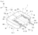
- FIG. 1 is a schematic perspective view illustrating an entire reactor of the first embodiment.
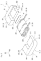
- FIG. 2 is a schematic perspective view illustrating a state in which the reactor of the first embodiment is disassembled.
- FIG. 3 is a cross-sectional view taken along line III-III of FIG.
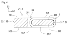
- FIG. 4 is a cross-sectional view taken along line IV-IV of FIG.
- FIG. 5 is an explanatory diagram illustrating a first outer circumferential shape of a coil, a second outer circumferential shape of a first end core, a third outer circumferential shape of a middle core, and a fourth outer circumferential shape of a side core in the reactor of embodiment 1.
- FIG. 6 is a schematic perspective view illustrating the entire reactor of the second embodiment.
- FIG. 6 is a schematic perspective view illustrating the entire reactor of the second embodiment.
- FIG. 7 is a schematic perspective view illustrating a state in which the reactor of the second embodiment is disassembled.
- FIG. 8 is a cross-sectional view taken along line VIII-VIII of FIG.
- FIG. 9 is a cross-sectional view taken along line IX-IX of FIG.
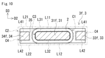
- Figure 10 is an explanatory diagram illustrating the first outer peripheral shape of the coil, the second outer peripheral shape of the first end core, the third outer peripheral shape of the middle core, the fourth outer peripheral shape of the first side core, and the fourth outer peripheral shape of the second side core in the reactor of embodiment 2.
- FIG. 11 is a schematic diagram showing a power supply system of a hybrid vehicle.
- FIG. 12 is a circuit diagram showing an example of a power conversion device including a converter.
- the area near the end faces of the coil is not covered by the first end core and the second end core, so magnetic flux is prone to leak from the area near the end faces of the coil.
- One of the objectives of this disclosure is to provide a reactor that has excellent heat dissipation properties and is less susceptible to magnetic flux leakage.
- the reactor of the present disclosure has excellent heat dissipation properties and is less susceptible to magnetic flux leakage.
- a reactor includes a coil made of a spirally wound winding and a core formed to pass through the inside and outside of the coil.
- a first outer peripheral shape of the coil is rectangular when viewed from a first direction along the axis of the coil.
- the outer peripheral surface of the coil has a first coil surface and a second coil surface that are along each of the long sides of the first outer peripheral shape and face each other.
- the core has a middle core disposed inside the coil, a first end core connected to a first end of the middle core, and a second end core connected to a second end of the middle core.
- Each of the outer peripheral surfaces of the first end core and the second end core has a first core surface and a second core surface that face each other.
- Each of the first core surfaces of the first end core and the second end core is substantially flush with the first coil surface.
- the first end and second end of the winding are drawn out in a direction along each of the long sides.
- the reactor (1) above has excellent heat dissipation properties.
- the first and second ends of the winding are drawn out in the direction along each of the long sides.
- the first core surface of the first end core and the first core surface of the second end core are substantially flush with the first coil surface. Therefore, when the reactor (1) above is installed on a planar installation target, the first coil surface, the first core surface of the first end core, and the first core surface of the second end core can be brought into contact with the installation target without the first and second ends of the winding interfering with the installation target.
- the reactor (1) above can have a larger contact area with the installation target than the reactor X in which only the first coil surface of the coil is in contact with the installation target without the first core surface of the first end core and the first core surface of the second end core being in contact with the installation target.
- the reactor (1) above is easier to transmit not only the heat of the coil but also the heat of the first end core and the second end core to the installation target than the reactor X.
- the reactor (1) above is easier to improve heat dissipation than the reactor X above.
- the reactor (1) above magnetic flux is less likely to leak from near the end faces of the coil.
- the first core faces of the first end core and the second end core are each substantially flush with the first coil face, so that the end faces of the coil are covered by the first end core and the second end core. Therefore, the reactor (1) above is easier to reduce leakage magnetic flux from near the end faces of the coil compared to reactor Y, in which the end faces of the coil are not covered by the first end core and the second end core, but are exposed from the first end core and the second end core.
- the reactor (1) above is easier to shorten the length along the first direction of the reactor. If the volumes of the first end core and the second end core are constant, the reactor (1) above has a longer length between the first core surface and the second core surface of the first end core and a longer length between the first core surface and the second core surface of the second end core than the reactor Y above. Therefore, if the volumes of the first end core and the second end core are constant, the reactor (1) above is easier to shorten the length along the first direction of the first end core and the second end core than the reactor Y above.
- each of the second core surfaces of the first end core and the second end core may be substantially flush with the second coil surface.
- the reactor (2) is less likely to leak magnetic flux from near the end face of the coil than reactor Z in which the first core surface of the first end core, the first core surface of the second end core, and the first coil surface are substantially flush with each other, and the second core surface of the first end core, the second core surface of the second end core, and the second core surface of the middle core described below are substantially flush with each other. This is because the reactor (2) has a larger area of the end face of the coil covered by the first end core and the second end core compared to reactor Z. The reactor (2) has more options for the surface to be brought into contact with the installation target compared to reactor Z.
- the reactor (2) can bring the first coil surface, the first core surface of the first end core, and the first core surface of the second end core into contact with the installation target, and can also bring the second coil surface, the second core surface of the first end core, and the second core surface of the second end core into contact with the installation target.
- the reactor (2) above if the volumes of the first end core and the second end core are constant, it is easier to shorten the length of the first end core and the second end core along the first direction compared to the reactor Y above, so it is easier to shorten the length of the reactor along the first direction.
- the second outer peripheral shape of the first end core and the second end core when viewed from the first direction may be rectangular, and the first core surface and the second core surface of each of the first end core and the second end core may be surfaces that extend along the long sides of the second outer peripheral shape.
- the reactor (3) above has a wide first core surface of the first end core and a wide first core surface of the second end core, making it easy to increase the contact area between the reactor and the object on which it is to be installed.
- the reactor (3) above has a wide second core surface of the first end core and a wide second core surface of the second end core, making it easy to increase the contact area between the reactor and the object on which it is to be installed.
- the core may further include a first side core and a second side core arranged in parallel to the middle core so as to sandwich the middle core without the coil being arranged therebetween.
- the first end core is connected to a first end of the first side core and a first end of the second side core
- the second end core is connected to a second end of the first side core and a second end of the second side core.
- the reactor (4) above has excellent heat dissipation properties and is less susceptible to magnetic flux leakage.
- the thickness of the first side core may be thinner than the thicknesses of the first end core and the second end core.
- the reactor (5) above allows the first and second ends of the winding to be pulled out without interfering with the first side core.
- the thickness of the second side core may be thinner than the thicknesses of the first end core and the second end core.
- the reactor (6) above has many options for the direction in which the first and second ends of the windings are pulled out. This is because the first and second ends of the windings can be pulled out without interfering with the second side core.
- the core may further include a side core arranged in parallel to the middle core without the coil being arranged therein.
- the first end core is connected to a first end of the side core, and the second end core is connected to a second end of the side core.
- the reactor (7) above has excellent heat dissipation properties and is less susceptible to magnetic flux leakage.
- the outer peripheral surface of the side core may have a first core surface and a second core surface facing each other, and the first core surface of the side core may be substantially flush with the first coil surface.
- the reactor (8) above has excellent heat dissipation properties because the first core surface of the side core is also in contact with the object to be installed.
- the second core surface of the side core may be substantially flush with the second coil surface.
- the reactor (9) above has many options for the surface to be brought into contact with the installation object. This is because the reactor (9) above can bring the first coil surface, the first core surface of the first end core, the first core surface of the second end core, and the first surface of the side core into contact with the installation object, and can also bring the second coil surface, the second core surface of the first end core, the second core surface of the second end core, and the second core surface of the side core into contact with the installation object.
- a converter according to one embodiment of the present disclosure includes any one of the reactors described above in (1) to (9).
- the converter has excellent performance because it is equipped with the reactor.
- a power conversion device includes the converter described above in (10).
- the power conversion device has excellent performance because it is equipped with the converter.
- the reactor 1 includes a coil 2 and a core 3.
- the coil 2 is composed of a winding 20 wound in a spiral shape.
- the core 3 is formed so as to pass through the inside and outside of the coil 2.
- the core 3 forms a magnetic path that passes through the inside and outside of the coil 2.
- One of the features of the reactor 1 of the present embodiment is that it satisfies the following requirements (a) to (c).
- the coil 2 has a particular shape.
- the first end 21 and the second end 22 of the winding 20 are drawn out in a particular direction.
- a specific surface of coil 2 and a specific surface of core 3 are flush with each other.
- the first direction D1 is a direction along the axis of the coil 2.
- the second direction D2 is a direction along a first long side L11, which will be described later, as shown in FIG.
- the third direction D3 is a direction perpendicular to both the first direction D1 and the second direction D2.
- the length along the second direction D2 is referred to as the width.
- the length along the third direction D3 is referred to as the thickness.
- the shape of the core 3 when viewed from the third direction D3 is planar.
- the number of coils 2 is one.
- the reactor 1 having one coil 2 is easier to mold than the reactor 1 having multiple coils 2.
- the reactor 1 having one coil 2 has fewer parts than the reactor 1 having multiple coils 2. Therefore, the reactor 1 having one coil 2 is superior in productivity. Since the number of coils 2 is one, the width of the reactor 1 can be shortened compared to the case where multiple coils 2 are arranged in parallel in the second direction D2.
- the shape of the coil 2 is a rectangular tube. Since the shape of the coil 2 is a rectangular tube, the contact area between the coil 2 and the planar installation target can be easily increased compared to the case where the coil 2 is a circular tube with the same cross-sectional area.
- the reactor 1 easily transfers the heat of the coil 2 to the installation target.
- the installation target is, for example, a cooling base.
- the four corners of the coil 2 are rounded.
- the first outer peripheral shape C1 of the coil 2 viewed from the first direction D1 is rectangular. That is, the end face shape of the coil 2 as viewed from the first direction D1 is a rectangular frame shape.
- Fig. 5 shows a state in which the reactor 1 is cut at the same position as in Fig. 4.
- the first outer peripheral shape C1 shown in Fig. 5 is shown by a two-dot chain line that is larger than the outer peripheral contour line of the coil 2 in order to distinguish it from the outer peripheral contour line of the coil 2. This point is also true in Fig. 10 referred to in the second embodiment.
- the outer peripheral surface of coil 2 has a first coil surface 251 and a second coil surface 252 facing each other, as shown in FIG. 3.
- the first coil surface 251 is aligned along the first long side L11 of the rectangular first outer peripheral shape C1 shown in FIG. 5.
- the second coil surface 252 is aligned along the second long side L12 of the rectangular first outer peripheral shape C1 shown in FIG. 5.
- the first coil surface 251 and the second coil surface 252 are flat surfaces.
- the winding 20 constituting the coil 2 is a series of windings with no joints, as shown in Figures 1 and 2.
- the winding 20 is a known winding.
- the winding 20 of this embodiment uses coated rectangular wire.
- the conductor wire of the coated rectangular wire is composed of rectangular copper wire.
- the insulating coating of the coated rectangular wire is made of enamel.
- the coil 2 of this embodiment is made of coated rectangular wire wound edgewise. Unlike this embodiment, the coil 2 may be made of coated rectangular wire wound flatwise.
- the first end 21 of the winding 20 is drawn out at the first end of the coil 2 in the first direction D1 in a direction along the first long side L11 of the rectangular first outer peripheral shape C1 shown in FIG. 5, i.e., along the first coil surface 251 shown in FIGS. 1 and 2.
- the second end 22 of the winding 20 is drawn out at the second end of the coil 2 in the first direction D1 in a direction along the second long side L12 of the rectangular first outer peripheral shape C1 shown in FIG. 5, i.e., along the second coil surface 252 shown in FIGS. 1 and 2.
- the first end 21 and the second end 22 are drawn out in the same direction.
- the first end 21 and the second end 22 are drawn out so as to move away from the side core 32 described later.
- the insulating coating of the first end 21 and the second end 22 has been stripped away to expose the conductor wire.
- a terminal member is connected to the exposed conductor wire.
- the terminal member is not shown in the figure.
- An external device is connected to the coil 2 via this terminal member.
- the external device is not shown in the figure.
- the external device is, for example, a power source that supplies power to the coil 2.
- [core] 1 the planar shape of the core 3 is O-shaped.
- the core 3 has a first end core 35, a second end core 36, a middle core 31, and a side core 32, as shown in FIG.
- the first end core 35 connects a first end of the middle core 31 to a first end of the side core 32.
- the second end core 36 connects a second end of the middle core 31 to a second end of the side core 32.
- the first end core 35 and the second end core 36 have the same shape.
- the first end core 35 and the second end core 36 are shaped like a quadrangular prism.
- the second outer peripheral shape C2 of the first end core 35 as viewed from the first direction D1 is rectangular.
- the second outer peripheral shape C2 shown in FIG. 5 is shown by a two-dot chain line larger than the outer peripheral contour line of the first end core 35 to distinguish it from the outer peripheral contour line of the first end core 35.
- the second outer peripheral shape of the second end core 36 as viewed from the first direction D1 is also rectangular.
- the four corners of the second outer peripheral shape C2 are angular, but may be rounded.
- the width of the first end core 35 is larger than the thickness of the first end core 35.
- the width of the second end core 36 is larger than the thickness of the second end core 36.
- the width of the first end core 35 and the width of the second end core 36 are the same.
- the thickness of the first end core 35 and the thickness of the second end core 36 are the same.
- the outer peripheral surface of the first end core 35 has a first core surface 351 and a second core surface 352 that face each other, as shown in Figures 3 and 4.
- the first core surface 351 is aligned along the first long side L21 of the rectangular second outer peripheral shape C2 shown in Figure 5.
- the second core surface 352 is aligned along the second long side L22 of the rectangular second outer peripheral shape C2 shown in Figure 5.
- the planar shape of the first core surface 351 and the second core surface 352 is a trapezoid that narrows from a first end surface proximal to the middle core 31 and side core 32 of the first end core 35 toward a second end surface distal to the middle core 31 and side core 32, as shown in Figures 1 and 2.
- the outer peripheral surface of the second end core 36 has a first core surface 361 and a second core surface 362 that face each other, as shown in Figures 2 and 3.
- the first core surface 361 is along the first long side of the rectangular second outer peripheral shape.
- the second core surface 362 is along the second long side of the rectangular second outer peripheral shape.
- the planar shape of the first core surface 361 and the second core surface 362 is a trapezoid that narrows from a first end surface proximal to the middle core 31 and side core 32 of the second end core 36 toward a second end surface distal to the middle core 31 and side core 32, as shown in Figures 1 and 2.
- the first core surface 351 and the first core surface 361 are substantially flush with the first coil surface 251, as shown in FIG. 3.
- the maximum difference along the third direction D3 between the first core surface 351 and the first core surface 361 and the first coil surface 251 can be reduced, and the maximum difference can be brought closer to 0 (zero).
- the first end 21 and the second end 22 of the reactor 1 are drawn out in the direction along the first long side L11 and the second long side L12 of the rectangular first outer peripheral shape C1 shown in FIG. 5, and the first coil surface 251, the first core surface 351, and the first core surface 361 are flush with each other.
- Reactor 1 when the reactor 1 is installed on a planar installation target, the first coil surface 251, the first core surface 351, and the first core surface 361 can be brought into contact with the installation target without the first end 21 and the second end 22 interfering with the installation target. Therefore, compared to Reactor X, in which the first core surface 351 and the first core surface 361 do not come into contact with the installation object, and only the first coil surface 251 comes into contact with the installation object, Reactor 1 can increase the contact area between Reactor 1 and the installation object.
- the first core surface 351 and the second core surface 352 are wide surfaces that are aligned along the first long side L21 and the second long side L22 of the rectangular second outer peripheral shape C2 shown in FIG. 5, so that the contact area with the installation target can be increased.
- the reactor 1 not only the heat of the coil 2 but also the heat of the first end core 35 and the second end core 36 are easily transferred to the installation target, compared to the reactor X. Therefore, the reactor 1 is easier to improve heat dissipation, compared to the reactor X. That is, the fact that the first core surface 351 and the first core surface 361 and the first coil surface 251 shown in FIG.
- the flatness of the first core surface 351, the first core surface 361, and the first coil surface 251, which are substantially flush with each other, may be, for example, 0.4 mm or less, and may further be 0.2 mm or less, 0.1 mm or less, or 0.05 mm or less.
- the flatness referred to here complies with JIS B 0621:1984 Definition and display of geometric deviation.
- first core surface 351 and first core surface 361 are substantially flush with first coil surface 251, so that the end faces of coil 2 are covered by first end core 35 and second end core 36. That is, the end faces of coil 2 face first end core 35 and second end core 36. Therefore, reactor 1 is easier to reduce leakage magnetic flux from near the end faces of coil 2 compared to reactor Y, in which the end faces of coil 2 are not covered by first end core 35 and second end core 36 and are exposed from first end core 35 and second end core 36. Therefore, reactor 1 is less susceptible to magnetic flux leakage from near the end faces of coil 2 compared to reactor Y.
- the second core surface 352 and the second core surface 362 are substantially flush with the second coil surface 252.
- the maximum difference along the third direction D3 between the second core surface 352 and the second core surface 362 and the second coil surface 252 can be reduced, and the maximum difference can be brought closer to 0 (zero).
- the first core surface 351, the first core surface 361, and the first coil surface 251 are substantially flush with each other, and magnetic flux is less likely to leak from the vicinity of the end surface of the coil 2 compared to the reactor Z in which the second core surface 352, the second core surface 362, and the second core surface 312 are substantially flush with each other.
- the reactor 1 has a larger area of the end surface of the coil 2 covered by the first end core 35 and the second end core 36 compared to the reactor Z. That is, the area in which the end surface of the coil 2 faces the first end core 35 and the second end core 36 is larger.
- the reactor 1 has more options for the surface to be in contact with the installation target than the reactor Z. This is because the reactor 1 can have the first coil surface 251, the first core surface 351, and the first core surface 361 in contact with the installation target, and can also have the second coil surface 252, the second core surface 352, and the second core surface 362 in contact with the installation target. The fact that the second core surface 352 and the second core surface 362 shown in FIG.
- the second coil surface 252 are substantially flush with the second coil surface 252 means that the thicknesses of the first end core 35, the second end core 36, and the coil 2 are dimensions that easily ensure heat dissipation.
- the flatness of the second core surface 352, the second core surface 362, and the second coil surface 252 that are substantially flush may be, for example, 0.4 mm or less, and may further be 0.2 mm or less, 0.1 mm or less, or 0.05 mm or less. Unlike this embodiment, the second core surface 352 and the second core surface 362 do not have to be flush with the second coil surface 252.
- the middle core 31 has a portion disposed inside the coil 2.
- the shape of the middle core 31 in this embodiment corresponds to the inner peripheral contour shape of the coil 2.
- the middle core 31 is shaped like a quadrangular prism.
- the third outer peripheral shape C3 of the middle core 31 as viewed from the first direction D1 is rectangular.
- the third outer peripheral shape C3 shown in Fig. 5 is shown by a two-dot chain line larger than the outer peripheral contour line of the middle core 31 in order to distinguish it from the outer peripheral contour line of the middle core 31.
- This point is also the same in Fig. 10 referred to in the second embodiment.
- Each of the four corners of the third outer peripheral shape C3 is rounded so as to follow each of the four corners of the inner peripheral surface of the coil 2.
- the middle core 31 and the side core 32 are arranged in parallel along the first long side L31 of the third outer peripheral shape C3.
- the width of the middle core 31 is greater than the thickness of the middle core 31. In this embodiment, the width of the middle core 31 is greater than the width of the side core 32.
- the coil 2 is arranged in the middle core 31 which is wider than the side core 32, and therefore the width of the coil 2 is wider than that of the reactor W in which the coil 2 is arranged in the middle core 31 which has the same width as the side core 32.
- the reactor 1 When the reactor 1 is installed on a planar installation target, the wide surface of the coil 2 comes into contact with the installation target. Therefore, the reactor 1 can have a larger contact area between the coil 2 and the installation target than the reactor W. The reactor 1 can easily transfer the heat of the coil 2 to the installation target than the reactor W.
- the reactor 1 has excellent heat dissipation properties.
- the coil 2 is arranged in the middle core 31 which is wider than the side core 32, and therefore the cross-sectional area of the coil 2 can be larger than that of the reactor W. Therefore, compared to the reactor W, the reactor 1 is easier to increase the inductance even though it has only one coil 2. Therefore, the reactor 1 has excellent inductance.
- the thickness of the middle core 31 is smaller than the thickness of the first end core 35.
- the outer peripheral surface of the middle core 31 has a first core surface 311 and a second core surface 312 that face each other.
- the first core surface 311 is aligned along the first long side L31 of the rectangular third outer peripheral shape C3 shown in FIG. 5.
- the second core surface 312 is aligned along the second long side L32 of the rectangular third outer peripheral shape C3 shown in FIG. 5.
- the middle core 31 of this embodiment is composed of two core portions, a first middle core portion 31f and a second middle core portion 31s. Unlike this embodiment, the middle core 31 may be composed of a single member.
- the side core 32 is arranged in parallel with the middle core 31 without the coil 2 being arranged thereon.
- the side core 32 has a rectangular prism shape.
- the fourth outer peripheral shape C4 of the side core 32 when viewed from the first direction D1 is rectangular.
- the fourth outer peripheral shape C4 shown in Fig. 5 is shown by a two-dot chain line larger than the outer peripheral contour line of the side core 32 in order to distinguish it from the outer peripheral contour line of the side core 32. This point is also the same in Fig. 10 referred to in the second embodiment.
- the four corners of the fourth outer peripheral shape C4 are angular, they may be rounded.
- the width of the side core 32 is smaller than the width of the middle core 31. Unlike this embodiment, the width of the side core 32 may be equal to the width of the middle core 31. In this embodiment, the width of the side core 32 is larger than the thickness of the side core 32. Unlike this embodiment, the width of the side core 32 may be equal to the thickness of the side core 32. The thickness of the side core 32 in this embodiment is larger than the thickness of the middle core 31. Unlike this embodiment, the thickness of the side core 32 may be equal to the thickness of the middle core 31. The thickness of the side core 32 in this embodiment is the same as the thickness of the first end core 35 and the thickness of the second end core 36. Unlike this embodiment, the thickness of the side core 32 may be smaller than the thickness of the first end core 35 and the thickness of the second end core 36.
- the outer peripheral surface of the side core 32 has a first core surface 321 and a second core surface 322 that face each other, as shown in Figs. 2 and 4.
- the first core surface 321 is aligned along the first long side L41 of the rectangular fourth outer peripheral shape C4 shown in Fig. 5.
- the second core surface 322 is aligned along the second long side L42 of the rectangular fourth outer peripheral shape C4 shown in Fig. 5.
- the first core surface 321 of this embodiment is substantially flush with the first coil surface 251. That is, as shown in FIG. 1, the first core surface 321 of this embodiment is also substantially flush with the first core surface 351 and the first core surface 361. By being substantially flush, the maximum difference along the third direction D3 between the first core surface 321 and the first coil surface 251 can be reduced, and the maximum difference can be brought closer to 0 (zero).
- the reactor 1 has excellent heat dissipation properties because the first core surface 321 is also brought into contact with the installation target.
- the flatness of the first core surface 321, which is substantially flush with the first coil surface 251, may be, for example, 0.4 mm or less, and may further be 0.2 mm or less, 0.1 mm or less, or 0.05 mm or less. Unlike this embodiment, the first core surface 321 does not have to be flush with the first coil surface 251.
- the second core surface 322 of this embodiment is substantially flush with the second coil surface 252, as shown in FIG. 4. That is, the second core surface 322 of this embodiment is substantially flush with the second core surface 352 and the second core surface 362. By being substantially flush, the maximum difference along the third direction D3 between the second core surface 322 and the second coil surface 252 can be reduced, and the maximum difference can be brought closer to 0 (zero).
- the reactor 1 has many options for the surface to be contacted with the installation object.
- the reactor 1 can have the first coil surface 251, the first core surface 351, the first core surface 361, and the first core surface 321 in contact with the installation object, and can also have the second coil surface 252, the second core surface 352, the second core surface 362, and the second core surface 322 in contact with the installation object.
- the flatness of the second core surface 322, which is substantially flush with the second coil surface 252, may be, for example, 0.4 mm or less, and may further be 0.2 mm or less, 0.1 mm or less, or 0.05 mm or less.
- the second core surface 322 does not have to be flush with the second coil surface 252.
- the length of the side core 32 along the first direction D1 is longer than the length of the middle core 31 along the first direction D1.
- the length of the middle core 31 along the first direction D1 does not include the length of the gap portion 3g along the first direction D1, which will be described later.
- the length of the middle core 31 along the first direction D1 is the total length of the length of the first middle core portion 31f along the first direction D1, which will be described later, and the length of the second middle core portion 31s along the first direction D1, which will be described later.
- the side core 32 of this embodiment is composed of two core portions, the first side core portion 32f and the second side core portion 32s.
- the length of the side core 32 along the first direction D1 is the total length of the length of the first side core portion 32f along the first direction D1, which will be described later, and the length of the second side core portion 32s along the first direction D1, which will be described later.
- the side core 32 may be composed of a single member.
- the core 3 of this embodiment is an assembly of a first core 3f and a second core 3s, as shown in Figures 1 and 2.
- the combination of the first core 3f and the second core 3s can be various combinations by appropriately selecting the shape of the first core 3f and the shape of the second core 3s.
- the shape of the first core 3f and the shape of the second core 3s may be symmetrical or asymmetrical with each other. Symmetrical means that the shapes and sizes are the same. Asymmetrical means that the shapes are different.
- the shape of the first core 3f and the shape of the second core 3s are symmetrical.
- the first core 3f and the second core 3s are divided along the first direction D1.
- the combination of the first core 3f and the second core 3s is a U-U type.
- the above combination may be a UI type, a J-L type, a J-J type, or an L-L type.
- the reactor 1 can be constructed by combining the first core 3f and the second core 3s with respect to the coil 2 along the axis of the coil 2. Therefore, the reactor 1 has excellent manufacturing workability. Between the first core 3f and the second core 3s, a gap portion 3g (described later) may be provided, or the gap portion 3g may not be provided.
- the first core 3f has at least one selected from the group consisting of at least a part of the middle core 31 and at least a part of the side core 32, and a first end core 35.
- the planar shape of the first core 3f is L-shaped.
- the planar shape of the first core 3f is U-shaped or J-shaped.
- the planar shape of the first core 3f is U-shaped.
- the planar shape of the first core 3f is J-shaped.
- the first core 3f of this embodiment has a U-shaped planar shape.
- the first core 3f of this embodiment has a first middle core portion 31f, a first side core portion 32f, and a first end core 35.
- the first core 3f is an integrally molded body of the first middle core portion 31f, the first side core portion 32f, and the first end core 35.
- the boundary between the first side core portion 32f and the first end core 35 is shown by a two-dot chain line in Figures 1 and 2.
- the first end core 35 connects the first middle core portion 31f and the first side core portion 32f.
- the first middle core portion 31f and the first side core portion 32f are provided at both ends in the direction along the width of the first end core 35.
- the second core 3s may be composed of only the second end core 36, or may have at least one selected from the group consisting of the remainder of the middle core 31 and the remainder of the side core 32 and the second end core 36.
- the planar shape of the second core 3s is I-shaped.
- the planar shape of the second core 3s is L-shaped.
- the planar shape of the second core 3s is U-shaped or J-shaped.
- the planar shape of the second core 3s is U-shaped.
- the remaining portions of the middle core 31 and the side core 32 have different lengths in the first direction D1, the second core 3s has a J-shape in plan view.
- the second core 3s of this embodiment has a U-shaped planar shape.
- the second core 3s of this embodiment has a second middle core portion 31s, a second side core portion 32s, and a second end core 36.
- the second core 3s is an integrally molded body of the second middle core portion 31s, the second side core portion 32s, and the second end core 36.
- the boundary between the second side core portion 32s and the second end core 36 is shown by a two-dot chain line in Figures 1 and 2.
- the second end core 36 connects the second middle core portion 31s and the second side core portion 32s.
- the second middle core portion 31s and the second side core portion 32s are provided at both ends in the direction along the width of the second end core 36.
- the length of the first middle core portion 31f along the first direction D1 is shorter than the length of the first side core portion 32f along the first direction D1.
- the length of the first middle core portion 31f along the first direction D1 may be longer than the length of the second middle core portion 31s along the first direction D1.
- the length of the first side core portion 32f along the first direction D1 may be longer than the length of the second side core portion 32s along the first direction D1.
- the length of the first middle core portion 31f along the first direction D1 may be equal to the length of the first side core portion 32f along the first direction D1.
- the first core 3f and the second core 3s are assembled so that the end face of the first side core portion 32f and the end face of the second side core portion 32s are in contact with each other.
- a gap portion 3g is formed between the end face of the first middle core portion 31f and the end face of the second middle core portion 31s.
- the gap portion 3g is formed of a member made of a material having a smaller relative magnetic permeability than the first core 3f and the second core 3s.
- the gap portion 3g is formed of a resin similar to the resin of the composite material molded body described later.
- the gap portion 3g may be formed of a mixed material in which the above-mentioned resin contains a filler described later.
- Each of the first core 3f and the second core 3s is composed of a composite material molded body or a powder compact.
- the first core 3f is composed of a composite material molded body
- the second core 3s is composed of a powder compact.
- both the first core 3f and the second core 3s may be composed of a composite material molded body or may be composed of a powder compact.
- a composite material compact is a compact in which soft magnetic powder is dispersed in resin.
- a composite material compact is obtained by filling a mold with a fluid material in which soft magnetic powder is dispersed in unsolidified resin, and then solidifying the resin.
- the content of soft magnetic powder in the resin of a composite material compact can be easily adjusted. Therefore, the magnetic properties of a composite material compact are easy to adjust.
- a composite material compact can be easily formed into a complex shape.
- the content of soft magnetic powder in a composite material compact is, for example, 20% by volume or more and 80% by volume or less.
- the content of resin in a composite material compact is, for example, 20% by volume or more and 80% by volume or less.
- a powder compact is a compact made by compressing and molding soft magnetic powder. Compared to composite material compacts, powder compacts can have a higher ratio of soft magnetic powder in the core. This makes it easier to improve the magnetic properties of powder compacts. Examples of magnetic properties include relative permeability and saturation magnetic flux density. Powder compacts also have excellent heat dissipation properties because they contain less resin and more soft magnetic powder than composite material compacts.
- the content of soft magnetic powder in the powder compact is, for example, 85% by volume or more and 99% by volume or less. This content is the percentage when the volume of the powder compact is 100%.
- the particles constituting the soft magnetic powder are, for example, soft magnetic metal particles, coated particles, or soft magnetic nonmetal particles.
- the coated particles include a soft magnetic metal particle and an insulating coating provided on the outer periphery of the soft magnetic metal particle.
- the soft magnetic metal is, for example, pure iron or an iron-based alloy.
- the iron-based alloy is, for example, an Fe-Si alloy or an Fe-Ni alloy.
- the insulating coating is, for example, a phosphate.
- the soft magnetic nonmetal is, for example, a ferrite.
- the resin of the composite material molded body is, for example, a thermosetting resin or a thermoplastic resin.
- the thermosetting resin is, for example, an epoxy resin, a phenolic resin, a silicone resin, or a urethane resin.
- the thermoplastic resin is, for example, a polyphenylene sulfide resin, a polyamide resin, a liquid crystal polymer, a polyimide resin, or a fluororesin.
- the polyamide resin is, for example, nylon 6, nylon 66, or nylon 9T.
- the composite material compact may contain a filler.
- the filler may be, for example, alumina or silica.
- the filler contributes to improving heat dissipation and electrical insulation.
- the content of the soft magnetic powder in the composite material molded body and the content of the soft magnetic powder in the powder molded body are regarded as equivalent to the area ratio of the soft magnetic powder in the cross section of the molded body.
- the content of the soft magnetic powder in the molded body is determined as follows.
- the cross section of the molded body is observed with a SEM (scanning electron microscope) to obtain an observation image.
- the cross section of the molded body is an arbitrary cross section.
- the magnification of the SEM is 200 times or more and 500 times or less.
- the number of observation images obtained is 10 or more.
- the total cross-sectional area is 0.1 cm2 or more.
- One observation image may be obtained for one cross section, or multiple observation images may be obtained for one cross section.
- Each of the obtained observation images is subjected to image processing to extract the outline of the particles.
- image processing include binarization processing.
- the area ratio of the soft magnetic particles is calculated in each observation image, and the average value of the area ratios is obtained.
- the average value is regarded as the content of the soft magnetic powder.
- the reactor 1 according to the second embodiment differs from the reactor 1 according to the first embodiment in that the combination of the first core 3f and the second core 3s is an E-E type. That is, the planar shape of the first core 3f and the planar shape of the second core 3s in the second embodiment are E-shaped.
- the following description will focus on the differences from the first embodiment. Description of the same configuration and effects as those in the first embodiment will be omitted.
- the first end 21 of the winding 20 is drawn out at a first end in the first direction D1 of the coil 2 in a direction along the first long side L11 of the rectangular first outer peripheral shape C1 shown in Figure 10, i.e., in a direction along the first coil surface 251 shown in Figures 6 and 7.
- the second end 22 of the winding 20 is drawn out at a second end in the first direction D1 of the coil 2 in a direction along the second long side L12 of the rectangular first outer peripheral shape C1 shown in Figure 10, i.e., in a direction along the second coil surface 252 shown in Figure 7.
- the first end 21 and the second end 22 are drawn out so as to move away from the second side core 34.
- the planar shape of the core 3 is a ⁇ -shape.
- the core 3 has a first end core 35, a second end core 36, a middle core 31, a first side core 33, and a second side core 34.
- the first end core 35 connects a first end of the middle core 31, a first end of the first side core 33, and a first end of the second side core 34.
- the second end core 36 connects a second end of the middle core 31, a second end of the first side core 33, and a second end of the second side core 34.
- the shapes and the second outer peripheral shape C2 of the first end core 35 and the second end core 36 of this embodiment are the same as those of the first end core 35 and the second end core 36 of the first embodiment.
- the relationship between the width and the thickness of the first end core 35 and the second end core 36 of this embodiment is the same as that of the first end core 35 and the second end core 36 of the first embodiment.
- the first core surface 351 of the first end core 35 and the first core surface 361 of the second end core 36 are substantially flush with the first coil surface 251.
- the flatness of the first core surface 351, the first core surface 361, and the first coil surface 251, which are substantially flush may be, for example, 0.4 mm or less, and may further be 0.2 mm or less, 0.1 mm or less, or 0.05 mm or less.
- the second core surface 352 of the first end core 35 and the second core surface 362 of the second end core 36 are substantially flush with the second coil surface 252. Being substantially flush, the maximum difference along the third direction D3 between the second core surface 352 and the second core surface 362 and the second coil surface 252 can be reduced, and the maximum difference can be brought closer to 0 (zero).
- the flatness of the second core surface 352, the second core surface 362, and the second coil surface 252, which are substantially flush, may be, for example, 0.4 mm or less, and may further be 0.2 mm or less, 0.1 mm or less, or 0.05 mm or less. Unlike this embodiment, the second core surface 352 and the second core surface 362 do not have to be flush with the second coil surface 252.
- the shape of the middle core 31 is a quadrangular prism corresponding to the inner peripheral contour shape of the coil 2.
- the third outer peripheral shape C3 of the middle core 31 when viewed from the first direction D1 is a rectangle.
- the width of the middle core 31 is greater than the thickness of the middle core 31.
- the width of the middle core 31 is greater than the width of the first side core 33 and the width of the second side core 34.
- the thickness of the middle core 31 is smaller than the thickness of the first end core 35 and the thickness of the second end core 36.
- the middle core 31 of this embodiment is composed of two core portions, a first middle core portion 31f and a second middle core portion 31s.
- first side core 33 and the second side core 34 are arranged in parallel to the middle core 31 so as to sandwich the middle core 31 without the coil 2 being arranged therebetween.
- the first side core 33 and the second side core 34 are arranged facing each other.
- the first side core 33 and the second side core 34 are arranged on the outer periphery of the coil 2.
- the first side core 33 and the second side core 34 have the same shape.
- the first side core 33 and the second side core 34 are each shaped like a rectangular prism.
- the fourth outer periphery shape C4 of each of the first side core 33 and the second side core 34 is square when viewed from the first direction D1. Unlike this embodiment, each of the fourth outer periphery shapes C4 may be rectangular.
- the width of the first side core 33 is the same as the thickness of the first side core 33.
- the width of the second side core 34 is the same as the thickness of the second side core 34.
- the thickness of the first side core 33 and the thickness of the second side core 34 are each the same as the thickness of the middle core 31.
- the thickness of the first side core 33 may be the same as the thickness of the middle core 31, and the thickness of the second side core 34 may be greater than the thickness of the middle core 31.
- the thickness of the first side core 33 and the thickness of the second side core 34 are each smaller than the thickness of the first end core 35 and the thickness of the second end core 36.
- the thickness of the first side core 33 may be smaller than the thickness of the first end core 35 and the thickness of the second end core 36, and the thickness of the second side core 34 may be the same as the thickness of the first end core 35 and the thickness of the second end core 36.
- the outer peripheral surface of the first side core 33 has a first core surface 331 and a second core surface 332 that face each other. As shown in Figure 9, the first core surface 331 and the second core surface 332 are aligned along the second direction D2. As shown in Figure 9, the outer peripheral surface of the second side core 34 has a first core surface 341 and a second core surface 342 that face each other. As shown in Figure 9, the first core surface 341 and the second core surface 342 are aligned along the second direction D2.
- the first core surface 331 is not flush with the first coil surface 251, as shown in FIG. 9.
- the first core surface 331 is not flush with the first core surface 351.
- the first core surface 331 is not flush with the first core surface 361, as shown in FIG. 6 and FIG. 7.
- the first core surface 331 is flush with the first core surface 311, as shown in FIG. 9.
- the second core surface 332 is not flush with the second coil surface 252.
- the second core surface 332 is not flush with the second core surface 352.
- the second core surface 332 is not flush with the second core surface 362, as shown in FIG. 6.
- the second core surface 332 is flush with the second core surface 312, as shown in FIG. 9.
- the first core surface 341 is not flush with the first coil surface 251.
- the first core surface 341 is not flush with the first core surface 351.
- the first core surface 341 is not flush with the first core surface 361.
- the first core surface 341 is flush with the first core surface 311.
- the second core surface 342 is not flush with the second coil surface 252.
- the second core surface 342 is not flush with the second core surface 352.
- the second core surface 342 is not flush with the second core surface 362.
- the second core surface 342 is flush with the second core surface 312.
- the length of the first side core 33 along the first direction D1 and the length of the second side core 34 along the first direction D1 are longer than the length of the middle core 31 along the first direction D1.
- the length of the middle core 31 along the first direction D1 is the total length of the length of the first middle core portion 31f along the first direction D1, which will be described later, and the length of the second middle core portion 31s along the first direction D1.
- the first side core 33 is composed of two core portions, the first side core portion 33f and the first side core portion 33s.
- the length of the first side core 33 along the first direction D1 is the total length of the length of the first side core portion 33f along the first direction D1, which will be described later, and the length of the first side core portion 33s along the first direction D1.
- the second side core 34 is composed of two core portions, the second side core portion 34f and the second side core portion 34s.
- the length of the second side core 34 along the first direction D1 is the total length of the length of the second side core portion 34f along the first direction D1 and the length of the second side core portion 34s along the first direction D1, which will be described later.
- the first side core 33 may be made of a single member.
- the second side core 34 may be made of a single member.
- the combination of the first core 3f and the second core 3s is an E-E type.
- the combination may be an E-I type, an E-T type, an E-U type, an F-F type, an F-L type, or an U-T type.
- the reactor 1 can be constructed by combining the first core 3f and the second core 3s with respect to the coil 2 along the axis of the coil 2. Therefore, the reactor 1 has excellent manufacturing workability.
- a gap portion 3g which will be described later, may be provided between the first core 3f and the second core 3s, or the gap portion 3g may not be provided.
- the first core 3f may have at least a first end core 35.
- the first core 3f may have at least one selected from the group consisting of at least a part of the middle core 31, at least a part of the first side core 33, and at least a part of the second side core 34, in addition to the first end core 35.
- the planar shape of the first core 3f is T-shaped.
- the planar shape of the first core 3f is L-shaped.
- the first core 3f of this embodiment has an E-shaped planar shape.
- the first core 3f of this embodiment has a first middle core portion 31f, a first side core portion 33f, a second side core portion 34f, and a first end core 35.
- the first core 3f is an integral molded body of the first middle core portion 31f, the first side core portion 33f, the second side core portion 34f, and the first end core 35.
- the first end core 35 connects the first middle core portion 31f, the first side core portion 33f, and the second side core portion 34f.
- the first side core portion 33f and the second side core portion 34f are provided at both ends in the direction along the width of the first end core 35.
- the first middle core portion 31f is provided in the center of the first end core 35.
- the first core 3f is composed of a molded body of a composite material.
- the second core 3s has at least a second end core 36.
- the second core 3s may have at least one selected from the group consisting of the remainder of the middle core 31, the remainder of the first side core 33, and the remainder of the second side core 34, in addition to the second end core 36.
- the planar shape of the second core 3s is I-shaped.
- the planar shape of the second core 3s is T-shaped.
- the planar shape of the second core 3s is L-shaped.
- the planar shape of the second core 3s is F-shaped.
- the planar shape of the second core 3s is U-shaped.
- the planar shape of the second core 3s is E-shaped.
- the reactor 1 of the first and second embodiments can be used for applications that satisfy the following energization conditions: a maximum DC current of about 100 A to 1000 A, an average voltage of about 100 V to 1000 V, and an operating frequency of about 5 kHz to 100 kHz.
- the reactor 1 of the first and second embodiments can be used as a component of a converter mounted on a vehicle 1200, typically an electric vehicle, a hybrid vehicle, or a fuel cell vehicle, or as a component of a power conversion device including the converter.
- the vehicle 1200 includes a main battery 1210, a power conversion device 1100 connected to the main battery 1210, and a motor 1220 that is driven by power supplied from the main battery 1210 and used for traveling.
- the motor 1220 is typically a three-phase AC motor.
- the motor 1220 drives the wheels 1250 when traveling, and functions as a generator during regeneration.
- the vehicle 1200 includes an engine 1300 in addition to the motor 1220.
- FIG. 11 shows an example in which the charging point of the vehicle 1200 is an inlet. Although not shown in the figure, the charging point of the vehicle 1200 can be configured to include a plug.
Landscapes
- Engineering & Computer Science (AREA)
- Power Engineering (AREA)
- Coils Of Transformers For General Uses (AREA)
- Dc-Dc Converters (AREA)
Priority Applications (1)
| Application Number | Priority Date | Filing Date | Title |
|---|---|---|---|
| CN202380083596.3A CN120322837A (zh) | 2022-12-09 | 2023-12-04 | 电抗器、转换器以及电力变换装置 |
Applications Claiming Priority (2)
| Application Number | Priority Date | Filing Date | Title |
|---|---|---|---|
| JP2022-197372 | 2022-12-09 | ||
| JP2022197372A JP2024083069A (ja) | 2022-12-09 | 2022-12-09 | リアクトル、コンバータ、および電力変換装置 |
Publications (1)
| Publication Number | Publication Date |
|---|---|
| WO2024122508A1 true WO2024122508A1 (ja) | 2024-06-13 |
Family
ID=91379324
Family Applications (1)
| Application Number | Title | Priority Date | Filing Date |
|---|---|---|---|
| PCT/JP2023/043336 Ceased WO2024122508A1 (ja) | 2022-12-09 | 2023-12-04 | リアクトル、コンバータ、および電力変換装置 |
Country Status (3)
| Country | Link |
|---|---|
| JP (1) | JP2024083069A (https=) |
| CN (1) | CN120322837A (https=) |
| WO (1) | WO2024122508A1 (https=) |
Citations (3)
| Publication number | Priority date | Publication date | Assignee | Title |
|---|---|---|---|---|
| JP2016171099A (ja) * | 2015-03-11 | 2016-09-23 | 三菱電機株式会社 | リアクトル装置 |
| JP2017011186A (ja) * | 2015-06-24 | 2017-01-12 | 株式会社オートネットワーク技術研究所 | リアクトル、及びリアクトルの製造方法 |
| JP2022075188A (ja) * | 2020-11-06 | 2022-05-18 | スミダコーポレーション株式会社 | 昇圧リアクトル装置 |
-
2022
- 2022-12-09 JP JP2022197372A patent/JP2024083069A/ja active Pending
-
2023
- 2023-12-04 WO PCT/JP2023/043336 patent/WO2024122508A1/ja not_active Ceased
- 2023-12-04 CN CN202380083596.3A patent/CN120322837A/zh active Pending
Patent Citations (3)
| Publication number | Priority date | Publication date | Assignee | Title |
|---|---|---|---|---|
| JP2016171099A (ja) * | 2015-03-11 | 2016-09-23 | 三菱電機株式会社 | リアクトル装置 |
| JP2017011186A (ja) * | 2015-06-24 | 2017-01-12 | 株式会社オートネットワーク技術研究所 | リアクトル、及びリアクトルの製造方法 |
| JP2022075188A (ja) * | 2020-11-06 | 2022-05-18 | スミダコーポレーション株式会社 | 昇圧リアクトル装置 |
Also Published As
| Publication number | Publication date |
|---|---|
| JP2024083069A (ja) | 2024-06-20 |
| CN120322837A (zh) | 2025-07-15 |
Similar Documents
| Publication | Publication Date | Title |
|---|---|---|
| CN104969314B (zh) | 电抗器、转换器以及电力转换装置 | |
| US12609231B2 (en) | Reactor, converter, and power conversion device | |
| JP2026003011A (ja) | リアクトル、コンバータ、及び電力変換装置 | |
| JP7566245B2 (ja) | リアクトル、コンバータ、及び電力変換装置 | |
| WO2024247671A1 (ja) | リアクトル、コンバータおよび電力変換装置 | |
| US12573531B2 (en) | Core piece, reactor, converter, and power conversion apparatus | |
| WO2024122508A1 (ja) | リアクトル、コンバータ、および電力変換装置 | |
| WO2024122509A1 (ja) | リアクトル、コンバータ、および電力変換装置 | |
| CN117941020A (zh) | 电抗器、转换器以及电力变换装置 | |
| JP7567740B2 (ja) | リアクトル、コンバータ、及び電力変換装置 | |
| JP7766866B2 (ja) | リアクトル、磁性コア、コンバータ、および電力変換装置 | |
| JP7810075B2 (ja) | リアクトル、磁性コア、コンバータ、および電力変換装置 | |
| JP7698243B2 (ja) | リアクトル、コンバータ、及び電力変換装置 | |
| JP7630774B2 (ja) | リアクトル、コンバータ、及び電力変換装置 | |
| WO2025182594A1 (ja) | リアクトル、コンバータ、および電力変換装置 | |
| JP7566238B2 (ja) | リアクトル、コンバータ、及び電力変換装置 | |
| WO2025047578A1 (ja) | リアクトル、コンバータ、および電力変換装置 | |
| JP2026048824A (ja) | リアクトル、分割片、コンバータ、及び電力変換装置 | |
| JP2024161152A (ja) | リアクトル、コンバータ、及び電力変換装置 | |
| WO2024257673A1 (ja) | コア片、リアクトル、コンバータ、および電力変換装置 |
Legal Events
| Date | Code | Title | Description |
|---|---|---|---|
| 121 | Ep: the epo has been informed by wipo that ep was designated in this application |
Ref document number: 23900623 Country of ref document: EP Kind code of ref document: A1 |
|
| DPE1 | Request for preliminary examination filed after expiration of 19th month from priority date (pct application filed from 20040101) | ||
| WWE | Wipo information: entry into national phase |
Ref document number: CN2023800835963 Country of ref document: CN Ref document number: 202380083596.3 Country of ref document: CN |
|
| NENP | Non-entry into the national phase |
Ref country code: DE |
|
| WWP | Wipo information: published in national office |
Ref document number: 202380083596.3 Country of ref document: CN |
|
| 122 | Ep: pct application non-entry in european phase |
Ref document number: 23900623 Country of ref document: EP Kind code of ref document: A1 |