WO2024122208A1 - 解重合反応監視装置、解重合反応監視方法、解重合反応監視プログラム - Google Patents
解重合反応監視装置、解重合反応監視方法、解重合反応監視プログラム Download PDFInfo
- Publication number
- WO2024122208A1 WO2024122208A1 PCT/JP2023/038254 JP2023038254W WO2024122208A1 WO 2024122208 A1 WO2024122208 A1 WO 2024122208A1 JP 2023038254 W JP2023038254 W JP 2023038254W WO 2024122208 A1 WO2024122208 A1 WO 2024122208A1
- Authority
- WO
- WIPO (PCT)
- Prior art keywords
- depolymerization
- agent
- depolymerization reaction
- reaction
- unit
- Prior art date
- Legal status (The legal status is an assumption and is not a legal conclusion. Google has not performed a legal analysis and makes no representation as to the accuracy of the status listed.)
- Ceased
Links
Images




Classifications
-
- B—PERFORMING OPERATIONS; TRANSPORTING
- B01—PHYSICAL OR CHEMICAL PROCESSES OR APPARATUS IN GENERAL
- B01J—CHEMICAL OR PHYSICAL PROCESSES, e.g. CATALYSIS OR COLLOID CHEMISTRY; THEIR RELEVANT APPARATUS
- B01J19/00—Chemical, physical or physico-chemical processes in general; Their relevant apparatus
- B01J19/0006—Controlling or regulating processes
-
- B—PERFORMING OPERATIONS; TRANSPORTING
- B01—PHYSICAL OR CHEMICAL PROCESSES OR APPARATUS IN GENERAL
- B01J—CHEMICAL OR PHYSICAL PROCESSES, e.g. CATALYSIS OR COLLOID CHEMISTRY; THEIR RELEVANT APPARATUS
- B01J19/00—Chemical, physical or physico-chemical processes in general; Their relevant apparatus
- B01J19/24—Stationary reactors without moving elements inside
-
- B—PERFORMING OPERATIONS; TRANSPORTING
- B01—PHYSICAL OR CHEMICAL PROCESSES OR APPARATUS IN GENERAL
- B01J—CHEMICAL OR PHYSICAL PROCESSES, e.g. CATALYSIS OR COLLOID CHEMISTRY; THEIR RELEVANT APPARATUS
- B01J2219/00—Chemical, physical or physico-chemical processes in general; Their relevant apparatus
- B01J2219/00049—Controlling or regulating processes
- B01J2219/00191—Control algorithm
- B01J2219/00211—Control algorithm comparing a sensed parameter with a pre-set value
- B01J2219/00213—Fixed parameter value
-
- C—CHEMISTRY; METALLURGY
- C08—ORGANIC MACROMOLECULAR COMPOUNDS; THEIR PREPARATION OR CHEMICAL WORKING-UP; COMPOSITIONS BASED THEREON
- C08J—WORKING-UP; GENERAL PROCESSES OF COMPOUNDING; AFTER-TREATMENT NOT COVERED BY SUBCLASSES C08B, C08C, C08F, C08G or C08H
- C08J11/00—Recovery or working-up of waste materials
- C08J11/04—Recovery or working-up of waste materials of polymers
- C08J11/10—Recovery or working-up of waste materials of polymers by chemically breaking down the molecular chains of polymers or breaking of crosslinks, e.g. devulcanisation
- C08J11/18—Recovery or working-up of waste materials of polymers by chemically breaking down the molecular chains of polymers or breaking of crosslinks, e.g. devulcanisation by treatment with organic material
- C08J11/22—Recovery or working-up of waste materials of polymers by chemically breaking down the molecular chains of polymers or breaking of crosslinks, e.g. devulcanisation by treatment with organic material by treatment with organic oxygen-containing compounds
- C08J11/24—Recovery or working-up of waste materials of polymers by chemically breaking down the molecular chains of polymers or breaking of crosslinks, e.g. devulcanisation by treatment with organic material by treatment with organic oxygen-containing compounds containing hydroxyl groups
-
- C—CHEMISTRY; METALLURGY
- C08—ORGANIC MACROMOLECULAR COMPOUNDS; THEIR PREPARATION OR CHEMICAL WORKING-UP; COMPOSITIONS BASED THEREON
- C08J—WORKING-UP; GENERAL PROCESSES OF COMPOUNDING; AFTER-TREATMENT NOT COVERED BY SUBCLASSES C08B, C08C, C08F, C08G or C08H
- C08J2367/00—Characterised by the use of polyesters obtained by reactions forming a carboxylic ester link in the main chain; Derivatives of such polymers
- C08J2367/02—Polyesters derived from dicarboxylic acids and dihydroxy compounds
- C08J2367/03—Polyesters derived from dicarboxylic acids and dihydroxy compounds the dicarboxylic acids and dihydroxy compounds having the hydroxy and the carboxyl groups directly linked to aromatic rings
-
- Y—GENERAL TAGGING OF NEW TECHNOLOGICAL DEVELOPMENTS; GENERAL TAGGING OF CROSS-SECTIONAL TECHNOLOGIES SPANNING OVER SEVERAL SECTIONS OF THE IPC; TECHNICAL SUBJECTS COVERED BY FORMER USPC CROSS-REFERENCE ART COLLECTIONS [XRACs] AND DIGESTS
- Y02—TECHNOLOGIES OR APPLICATIONS FOR MITIGATION OR ADAPTATION AGAINST CLIMATE CHANGE
- Y02W—CLIMATE CHANGE MITIGATION TECHNOLOGIES RELATED TO WASTEWATER TREATMENT OR WASTE MANAGEMENT
- Y02W30/00—Technologies for solid waste management
- Y02W30/50—Reuse, recycling or recovery technologies
- Y02W30/62—Plastics recycling; Rubber recycling
Definitions
- the present invention relates to a depolymerization reaction monitoring device, etc.
- Patent Document 1 discloses a method for recycling PET (polyethylene terephthalate) bottles by crushing the PET bottles to produce PET flakes, which are the raw material for new PET bottles. Specifically, mechanical recycling is known in which crushed PET bottles are heated and melted, and then PET flakes are obtained by solid-state polymerization, and chemical recycling is known in which crushed PET bottles are decomposed into intermediates such as bis(2-hydroxyethyl) terephthalate (BHET) or depolymerized polymers by a depolymerization reaction, and then PET flakes are obtained by a repolymerization reaction.
- BHET bis(2-hydroxyethyl) terephthalate
- the present invention was made in consideration of these circumstances, and aims to provide a depolymerization reaction monitoring device etc. that can efficiently grasp the progress of the depolymerization reaction.
- a depolymerization reaction monitoring device includes a depolymerization reaction tank in which a depolymerization reaction occurs by using a depolymerization agent to decompose polyester into depolymers, a characteristic measurement unit in the depolymerization reaction tank that measures the characteristics of the depolymerization agent in which the depolymerization agent has been dissolved, and a progress monitoring unit that monitors the progress of the depolymerization reaction based on the characteristics of the depolymerization agent measured by the characteristic measurement unit.
- the progress of the polyester depolymerization reaction in which the product depolymerization is dissolved in the reactant or catalyst depolymerization agent, can be efficiently monitored by measuring the characteristics of the depolymerization agent in the depolymerization reactor.
- Another aspect of the present invention is a method for monitoring a depolymerization reaction.
- This method includes the steps of: causing a depolymerization reaction in a depolymerization reaction tank in which a depolymerization agent decomposes polyester into depolymers; measuring the characteristics of the depolymerization agent in the depolymerization reaction tank in which the depolymerization agent has dissolved; and monitoring the progress of the depolymerization reaction based on the measured characteristics of the depolymerization agent.
- the present invention also encompasses any combination of the above components, and any expressions of these components converted into methods, devices, systems, recording media, computer programs, etc.
- the present invention makes it possible to efficiently grasp the progress of the depolymerization reaction.
- the configuration of the chemical recycling molding system is shown diagrammatically.
- the polymerization and depolymerization reactions of PET are shown diagrammatically.
- 1 shows a modified example of a by-product removal device.
- 1 shows a first embodiment of a depolymerization reaction monitoring device.
- 13 shows an example of monitoring the progress of the depolymerization reaction by the progress monitoring unit.
- 2 shows a second embodiment of the depolymerization reaction monitoring device.
- An example of dilution of the depolymerization agent by the depolymerization agent dilution section will be described.
- 10 is a flowchart of a specific example of a measurement procedure in the second embodiment.
- 1 shows a third embodiment of the depolymerization reaction monitoring device.
- 13 is a flowchart of a specific example of a measurement procedure in the third embodiment.
- FIG. 1 shows a schematic configuration of a chemical recycling molding system to which a depolymerization reaction monitoring device according to an embodiment of the present invention can be applied.
- the chemical recycling molding system includes a chemical recycling device 100 and an injection molding machine 1.
- the chemical recycling device 100 includes a polymer adjustment device 200, a depolymerization reaction tank 300, a polymerization reaction tank 400, a by-product removal device 500, and a polymer supply unit 600.
- the number of injection molding machines 1 (two are shown in FIG. 1), polymer adjustment devices 200, depolymerization reaction tanks 300, polymerization reaction tanks 400, by-product removal devices 500, and polymer supply units 600 may be set as desired.
- the processing performance can be improved so that these processing units do not become serious bottlenecks.
- the polymer adjustment device 200 adjusts the polymer such as PET that constitutes the first molded product such as a PET bottle for the subsequent depolymerization reaction tank 300. Specifically, the polymer adjustment device 200 performs processes such as crushing, heating and melting, and mixing on the first molded product such as a PET bottle, and adjusts the polymer such as PET to a state (phase, shape, size, etc.) suitable for the depolymerization reaction in the depolymerization reaction tank 300.
- the first molded product may be any molded product other than a bottle, such as a sheet, film, or fiber.
- the polymer that constitutes the first molded product may be any polymer or polymer other than PET, such as polyester (including PET), polyamide, or polyurethane.
- the depolymerization reaction tank 300 decomposes the polymer such as PET prepared by the polymer preparation device 200 into depolymerized polymers through a depolymerization reaction.
- the intermediate BHET is obtained as a depolymer through the depolymerization reaction in the depolymerization reaction tank 300.
- the depolymerized polymer obtained in the depolymerization reaction tank 300 may contain a monomer or monomers of the polymer.
- the monomers are, for example, ethylene glycol, terephthalic acid, dimethyl terephthalate, and ethylene terephthalate. The details will be described later, but the depolymerization reaction monitoring device according to an embodiment of the present invention is configured to include the depolymerization reaction tank 300.
- PET is decomposed by ethylene glycol (EG) as a depolymerization agent supplied from the depolymerization agent supply section 310 (FIG. 1) to the depolymerization reaction tank 300, and BHET is obtained as a depolymerized polymer.
- EG may be supplied in the polymer adjustment device 200 instead of or in addition to the depolymerization agent supply section 310.
- the inside of the depolymerization reaction tank 300 is maintained at a temperature suitable for the depolymerization reaction by a heater 320 (FIG.
- the temperature suitable for the depolymerization reaction of PET to BHET in FIG. 2 is between 180°C and 250°C, preferably between 230°C and 245°C, and more preferably between 235°C and 240°C.
- the pressure suitable for the depolymerization reaction of PET to BHET in FIG. 2 is between normal pressure (0 MPa, G) and 0.8 MPa, G, preferably between 0.4 MPa, G and 0.6 MPa, G, and more preferably between 0.45 MPa, G and 0.55 MPa, G.
- the unit of pressure, MPa, G is gauge pressure.
- the pressure in the depolymerization reaction tank 300 is adjusted by a pump (not shown) or the like that is provided in addition to the depolymerization reaction tank 300.
- agitator blades 330 for low viscosity are used to agitate the fluid in the depolymerization reaction tank 300 and promote the depolymerization reaction.
- agitator blades 330 for low viscosity include propeller blades, disk turbine blades, and paddle blades.
- foreign matter removal devices 340, 350, 360 that remove foreign matter from the fluid mainly composed of BHET as a depolymerized polymer.
- the foreign resin removal device 340 removes resins other than the target resin such as PET and/or its depolymerization polymers by the principles of flotation separation and sedimentation removal.
- the colored matter removal device 350 removes colored matter using activated carbon or the like.
- the metal ion removal device 360 removes metal ions by the principles of ion exchange or the like.
- a buffer tank 370 that temporarily stores the fluid mainly composed of BHET and the like after the foreign matter has been removed before supplying it to the polymerization reaction tank 400.
- the buffer tank 370 may be provided with a first preheater 371 for heating or keeping warm the depolymerization polymer (a fluid mainly composed of BHET, etc.) before it is supplied to the downstream polymerization reactor 400.
- the first preheater 371 may maintain the depolymerization polymer at a temperature (between 180°C and 250°C) similar to that of the heater 320 provided next to the depolymerization reactor 300, or may maintain the depolymerization polymer at a temperature suitable for polymerization reaction (between 250°C and 300°C) similar to that of the heater 410 provided next to the polymerization reactor 400 described below.
- the depolymerization polymer waiting to be input to the polymerization reactor 400 which typically has a slower processing speed or reaction speed than other processing units such as the depolymerization reactor 300 and the by-product removal device 500 described below, can be stored at an appropriate temperature.
- the overall capacity of the chemical recycling apparatus 100 can be increased, and the chemical recycling apparatus 100 can be operated stably and continuously while supplying appropriate amounts of reactants to each processing section, such as the depolymerization reaction tank 300, the polymerization reaction tank 400, the by-product removal device 500, and the polymer supply section 600, at appropriate times (without causing so-called "resin shortage").
- a preheating mechanism such as the first preheater 371 is not limited to the buffer tank 370, but can be provided in any manner at any location between the depolymerization reaction tank 300 and the polymerization reaction tank 400 (for example, the foreign matter removal devices 340, 350, 360).
- the polymerization reactor 400 synthesizes depolymerized polymers such as BHET, which have been produced in the depolymerization reactor 300 and from which foreign matter has been removed by the foreign matter removal devices 340, 350, and 360, into polymers through a polymerization reaction. If the depolymerized polymer produced in the depolymerization reactor 300 is BHET, the polymer PET is obtained again through a polymerization reaction in the polymerization reactor 400.
- depolymerized polymers such as BHET
- PET as the main product, which is a polymer
- EG as a by-product
- This EG may be circulated to the depolymerization agent supply section 310 and used in the depolymerization reaction of PET in the depolymerization reaction tank 300. Since the EG produced in the polymerization reaction tank 400 can be reused on the spot (depolymerization reaction tank 300) without being wasted, the operating efficiency of the chemical recycling apparatus 100 can be improved. In particular, the amount of EG purchased for the depolymerization reaction of PET in the depolymerization reaction tank 300 can be significantly reduced, which leads to a reduction in the operating costs of the chemical recycling apparatus 100.
- the inside of the polymerization reaction tank 400 is maintained at a temperature suitable for the polymerization reaction by a heater 410 (FIG. 1) or a warmer as a second heater attached to the polymerization reaction tank 400.
- the temperature suitable for the polymerization reaction of BHET to PET in FIG. 2 is between 250°C and 300°C, preferably between 260°C and 290°C, and more preferably between 270°C and 280°C.
- the polymerization heating temperature by the heater 410 attached to the polymerization reaction tank 400 is higher than the depolymerization heating temperature by the heater 320 attached to the depolymerization reaction tank 300.
- the PET In the polymerization reaction tank 400, PET with a high molecular weight and a high melting point is produced, but by maintaining the temperature higher than that of the depolymerization reaction tank 300 in which BHET with a low molecular weight and a low melting point is produced, the PET, which is the main product of the polymerization reaction tank 400, is maintained in a molten state.
- the polymerization reaction of BHET to PET in FIG. 2 is preferably performed in a vacuum state. For this reason, the polymerization reaction tank 400 is equipped with a vacuum pump (not shown).
- a high-viscosity agitator 420 is used to agitate the fluid in the polymerization reaction tank 400 and promote the polymerization reaction.
- high-viscosity agitator 420 include anchor blades and helical ribbon blades.
- the IV (intrinsic viscosity) value or inherent viscosity is known as a value that correlates with the degree of polymerization of polymers such as PET.
- the IV value (dL/g) is also used as an index of the use of polymers, and for PET, an IV value of about 0.72 or more can be used for bottles, an IV value of about 0.65 or more can be used for sheets and films, and an IV value of about 0.58 or more can be used for fibers.
- the aim is to finally obtain PET with an IV value that can be used for bottles and sheets.
- the IV value is also increased in the by-product removal device 500 downstream of the polymerization reaction tank 400, so the IV value of the PET synthesized in the polymerization reaction tank 400 may be relatively low.
- the IV value of the PET synthesized in the polymerization reaction tank 400 is between 0.2 and 0.7, preferably between 0.3 and 0.7, and more preferably between 0.3 and 0.55.
- a buffer tank 430 may be provided downstream of the polymerization reaction tank 400 to temporarily store the polymer synthesized in the polymerization reaction tank 400 before supplying it to the downstream by-product removal device 500 and/or polymer supply section 600.
- the buffer tank 430 may be provided with a second preheater 431 to heat or keep the polymer warm before supplying it to the downstream by-product removal device 500 and/or polymer supply section 600.
- the second preheater 431 may maintain the polymer at a temperature (between 250°C and 300°C) similar to that of the heater 410 provided next to the polymerization reaction tank 400, or may maintain the polymer at a temperature (between 250°C and 290°C) suitable for polymerization reaction similar to that of the heater 520 provided next to the by-product removal device 500 described later, or may maintain the polymer at a temperature (between 250°C and 290°C) similar to that of the heater 620 provided next to the polymer supply section 600 described later.
- the buffer tank 430 equipped with a preheating mechanism (second preheater 431) as necessary in front of the by-product removal device 500 and/or the polymer supply section 600, the polymer waiting to be fed to the by-product removal device 500 and/or the polymer supply section 600 can be stored while being kept at an appropriate temperature.
- the overall capacity of the chemical recycling apparatus 100 can be increased, and the chemical recycling apparatus 100 can be operated stably and continuously while supplying appropriate amounts of reactants to each processing section such as the depolymerization reaction tank 300, the polymerization reaction tank 400, the by-product removal device 500, and the polymer supply section 600 at the appropriate time (without causing so-called "resin shortage").
- the preheating mechanism such as the second preheater 431 is not limited to the buffer tank 430, but can be provided in any manner at any location between the polymerization reaction tank 400 and the by-product removal device 500 and/or at any location between the by-product removal device 500 and the polymer supply section 600.
- a by-product removal device 500 is provided downstream of the polymerization reaction tank 400 (and upstream of the polymer supply section 600 described below), through which PET (main product) and EG (by-product) produced by the polymerization reaction in the polymerization reaction tank 400 are passed and which removes EG as a by-product.
- the by-product removal device 500 in the illustrated example comprises a number of linear members 510 extending from above to below. Due to the increased surface area provided by the numerous linear members 510, the evaporation of EG adhering to the surface of each linear member 510 is promoted, and EG is effectively separated and removed from the highly viscous PET.
- This EG may be circulated to the depolymerization agent supply section 310 and used in the depolymerization reaction of PET in the depolymerization reaction tank 300.
- the EG separated and removed in the by-product removal device 500 can be reused on the spot (depolymerization reaction tank 300) without being wasted, improving the operating efficiency of the chemical recycling apparatus 100.
- the amount of EG purchased for the depolymerization reaction of PET in the depolymerization reaction tank 300 can be significantly reduced, leading to a reduction in the operating costs of the chemical recycling apparatus 100.
- the IV value of PET as the main product is increased.
- the IV value of PET after passing through the by-product removal device 500 is 0.7 or more, preferably 0.8 or more, and more preferably 0.85 or more.
- the inside of the by-product removal device 500 is maintained at a temperature suitable for the polymerization reaction by a heater 520 (FIG. 1) or a warmer as a second heater attached to the by-product removal device 500.
- the heating temperature by the heater 520 is between 250°C and 290°C, and preferably between 260°C and 280°C.
- the heating temperature by the heater 520 attached to the by-product removal device 500 is preferably higher than the polymerization heating temperature by the heater 410 attached to the polymerization reaction tank 400. Since the polymerization reaction proceeds more in the by-product removal device 500 than in the polymerization reaction tank 400, the molecular weight of the polymerized PET increases and the melting point increases.
- the PET as the product of the by-product removal device 500 can be maintained in a molten state.
- a heater or a warmer may be provided around the piping between the polymerization reaction tank 400 and the by-product removal device 500 as a second heater that heats or warms at least the polymerization heating temperature by the heater 410 provided next to the polymerization reaction tank 400.
- the polymerization reaction in the by-product removal device 500 is preferably carried out in a vacuum state, similar to the polymerization reaction in the polymerization reaction tank 400. For this reason, a vacuum pump (not shown) or the like is provided next to the by-product removal device 500. By creating a vacuum state (reduced pressure state) inside the by-product removal device 500, EG as a by-product can be efficiently removed.
- the configuration of the by-product removal device 500 is not limited to the "vertical type" shown in FIG. 1.
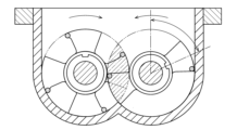
- a "horizontal two-axis" agitation device as shown in FIG. 3 may be used as the by-product removal device 500.
- This agitation device has two rotating shafts extending in a direction perpendicular to the paper surface of FIG. 3, and two agitation blades that rotate around the two rotating shafts to agitate the PET and EG as the agitation targets.
- the evaporation of EG is promoted by the agitation by the two agitation blades, so that EG is effectively separated and removed from the highly viscous PET. Details of the agitation device in FIG. 3 are disclosed in Japanese Patent No. 2925599, which is incorporated herein by reference.
- the polymer supply section 600 supplies polymers such as PET synthesized in the polymerization reactor 400 (or the polymerization reactor 400 and the by-product removal device 500) to the injection molding machine 1 which molds a second molded product such as a PET bottle.
- the polymer supply section 600 is equipped with a transfer pump 610 such as a gear pump or a screw pump which is suitable for supplying the high purity and high viscosity (i.e. high degree of polymerization or high IV value) PET from which the by-product EG has been removed in the by-product removal device 500 in a molten state to the injection molding machine 1.
- the polymer supply section 600 is provided with a heater 620 or a warmer as a first heater that heats or warms the polymer such as PET transferred to the injection molding machine 1 by the transfer pump 610 to maintain it in a molten state.
- the heating temperature by the heater 620 is between 250°C and 290°C, and preferably between 260°C and 280°C.
- the heating temperature (first heating temperature) by the heater 620 (first heater) provided in the polymer supply section 600 is preferably higher than the second heating temperature by the second heater such as the heater 410 provided next to the polymerization reaction tank 400, the heater 520 provided next to the by-product removal device 500, and a heater (not shown) provided between the polymerization reaction tank 400 and the by-product removal device 500.
- the polymerization reaction that started in the polymerization reaction tank 400 gradually progresses and is completed in the by-product removal device 500, so that the molecular weight of the polymer, such as PET, becomes larger and the melting point becomes higher in the polymer supply section 600 than in the polymerization reaction tank 400 and the by-product removal device 500.
- the high viscosity i.e. high polymerization degree or high IV value
- high melting point polymer such as PET
- a temperature gradient may be provided so that the heating temperature increases stepwise from the polymerization reaction tank 400 to the polymer supply section 600.
- the heating temperature by a heater (not shown) provided between the polymerization reaction tank 400 and the by-product removal device 500 may be made higher than the heating temperature by the heater 410 provided next to the polymerization reaction tank 400
- the heating temperature by the heater 520 provided next to the by-product removal device 500 may be made higher than the heating temperature by the heater (not shown)
- the heating temperature by the heater 620 provided in the polymer supply section 600 may be made higher than the heating temperature by the heater 520.
- a heater may be provided between the polymer supply section 600 and the injection molding machine 1 to heat or keep the polymer such as PET warm and maintain it in a molten state.
- the injection molding machine 1 molds the polymer such as PET in a molten state generated in the chemical recycling device 100 into a second molded product.
- the second molded product may be the same type as the first molded product that is subjected to processing such as crushing in the polymer adjustment device 200, or may be a different type.
- both the first molded product and the second molded product may be PET bottles.
- one of the first molded product and the second molded product may be a PET bottle, and the other may be a molded product other than a bottle, such as a sheet, film, or fiber.
- the IV value of the second molded product after recycling is lower than the IV value of the first molded product before recycling.
- the IV value of the second molded product after recycling can be made higher than the IV value of the first molded product before recycling.
- PET fiber with a low IV value as the first molded product can be recycled into a PET bottle with a high IV value as the second molded product.
- the injection molding machine 1 molds molten resin such as PET into a second molded product.
- An injection molding machine that uses molten resin as a raw material is disclosed in, for example, Patent Document 2.
- Patent Document 2 This application incorporates by reference the entire contents of that document (Japanese Application No. 2020-130985), filed on July 31, 2020.
- Japanese Application No. 2020-130985 Japanese Application No. 2020-130985
- multiple injection molding machines 1 may be provided in parallel.
- the molding machine to which molten resin or the like is supplied from the chemical recycling device 100 may be any molding machine (e.g., a compression molding machine) and is not limited to an injection molding machine.
- the polymer resynthesized in the polymerization reaction tank 400 is not made into flakes or pellets, but is supplied directly to the injection molding machine 1 by the polymer supply unit 600. Since the cooling and heating processes for flakes and pellets as in the past are no longer necessary, molded products such as PET bottles can be recycled with less energy than before.
- the polymer resynthesized in the polymerization reaction tank 400 is directly supplied to the injection molding machine 1, so it is necessary to quickly achieve the IV value of the polymer required for the molded product (second molded product).
- a by-product removal device 500 that has the function of promoting the polymerization reaction and increasing the IV value of the polymer is provided in addition to the polymerization reaction tank 400, so this requirement can be fully met.
- each of the polymer adjustment device 200, depolymerization reaction tank 300, polymerization reaction tank 400, by-product removal device 500, polymer supply unit 600, etc. is provided, but multiple of each may be provided. Such multiple processing units can execute equivalent processes in parallel, improving the processing performance of the processing unit group. Also, the difference in processing speed or reaction speed between each processing unit can be reduced by increasing the number of slower processing units.
- one or more of the processing units may accept external materials procured from a place or facility different from the chemical recycle molding system shown in FIG. 1, instead of or in addition to materials from the preceding processing unit.
- the processing units may accept external materials procured from a place or facility different from the chemical recycle molding system shown in FIG. 1, instead of or in addition to materials from the preceding processing unit.
- the processing units may accept external materials procured from a place or facility different from the chemical recycle molding system shown in FIG. 1, instead of or in addition to materials from the preceding processing unit.
- some of them may be supplied with depolymerized polymer from the depolymerization reaction tank 300, and the rest may be supplied with depolymerized polymer procured from the outside (synonymous with depolymerized polymer supplied from the depolymerization supply unit 300A described later).
- FIG. 4 shows a first embodiment of the depolymerization reaction monitoring device 30 according to the present invention.
- the depolymerization reaction monitoring device 30 includes the above-mentioned depolymerization reaction tank 300.
- the depolymerization reaction tank 300 causes a depolymerization reaction in which the polyester is decomposed into depolymers by a depolymerization agent.
- the polyester is polyethylene terephthalate (PET)
- the depolymerization agent is ethylene glycol (EG)
- BHET bis(2-hydroxyethyl) terephthalate
- the present invention is also applicable to other combinations of polyester, depolymerization agent, and depolymer.
- the polyester may be polypropylene terephthalate (PPT)
- the depolymerization agent may be propylene glycol (PG)
- the depolymer may be bis(2-hydroxypropyl) terephthalate (BHPT).
- the polyester may be polybutylene terephthalate (PBT)
- the depolymerization agent may be butylene glycol (BG)
- the depolymer may be bis(2-hydroxybutyl) terephthalate (BHBT).
- polyester, depolymerization agent, and depolymer have the common feature that the depolymerization product (BHET, BHPT, BHBT, etc.) dissolves in the depolymerization agent (EG, PG, BG, etc.), which is one of the reactants or catalysts in the depolymerization reaction, while the polyester (PET, PPT, PBT, etc.), which is the other reactant in the depolymerization reaction, does not dissolve in the depolymerization agent (EG, PG, BG, etc.).
- the depolymerization product BHET, BHPT, BHBT, etc.
- the depolymerization reaction monitoring device 30 according to this embodiment may be used to monitor the progress of the depolymerization reaction of polymers other than polyester, such as polyamides and polyurethanes, as long as similar characteristics are observed.
- the depolymerization reaction monitoring device 30 according to this embodiment can be applied in cases where the depolymerization product of the depolymerization reaction dissolves in the depolymerization material, which is one of the reactants or catalyst of the depolymerization reaction, while the polymer, which is the other reactant of the depolymerization reaction, is insoluble in the depolymerization material.
- the depolymerization reaction monitoring device 30 is not limited to the depolymerization reaction tank 300 provided in the chemical recycle molding system shown in FIG. 1, but can be applied to the depolymerization reaction tank 300 provided in any system or any single depolymerization reaction tank 300.
- only one depolymerization reaction monitoring device 30 is provided on the side of the depolymerization reaction tank 300, but any number (e.g., multiple) of depolymerization reaction monitoring devices may be provided on any part (e.g., bottom surface) not limited to the side of the depolymerization reaction tank 300.
- the depolymerization reaction monitoring device 30 may be provided in the rear stage of the depolymerization reaction tank 300 and in the front stage of the polymerization reaction tank 400.
- the depolymerization reaction monitoring device 30 may be provided in the piping between the depolymerization reaction tank 300 and the polymerization reaction tank 400 in FIG. 1 or in the buffer tank 370 in addition to or instead of the depolymerization reaction tank 300.
- the average degree of progress of the depolymerization reaction in the multiple depolymerization reaction tanks 300 can be grasped in a buffer tank 370 or the like downstream where the depolymerization product liquid is collected.
- any number of depolymerization reaction monitoring devices 30 may be provided at any location of each depolymerization reaction tank 300. It is preferable that the monitoring results by each depolymerization reaction monitoring device 30 in each depolymerization reaction tank 300 (particularly the measurement results by the characteristic measurement unit 33 and the monitoring results by the progress monitoring unit 37 described later) are shared or listed among the multiple depolymerization reaction tanks 300. For example, when multiple depolymerization reaction tanks 300 are connected in series, the progress of the depolymerization reaction in each phase can be precisely grasped by each depolymerization reaction monitoring device 30 provided in each depolymerization reaction tank 300.
- the residence time of the reaction liquid and/or the product liquid in each depolymerization reaction tank 300 and the timing and speed of movement of the reaction liquid and/or the product liquid between adjacent depolymerization reaction tanks 300 may be adaptively adjusted.
- the depolymerization reaction tank 300 comprises a tank body 31 in which a depolymerization reaction of polyester or polymer occurs, and a depolymerization agent flow section 32 through which a depolymerization agent such as EG flows between the tank body 31 and the tank body 31.
- the depolymerization agent flow section 32 constitutes a flow path for the depolymerization agent such as EG outside the tank body 31.
- one end 321 and the other end 322 of the tubular depolymerization agent flow section 32 are connected to different positions of the tank body 31.
- the depolymerization agent such as EG may flow from one end 321 to the other end 322 of the depolymerization agent flow section 32, or from the other end 322 of the depolymerization agent flow section 32 to one end 321.
- the depolymerization material flow section 32 is provided with a characteristic measurement section 33, an intrusion prevention section 34, a direction switching section 35, and a cooling section 36.
- the characteristic measuring unit 33 measures the characteristics of the depolymerization agent such as EG in which depolymerization polymers such as BHET are dissolved in the depolymerization reaction tank 300. Specifically, the characteristic measuring unit 33 measures the characteristics of the depolymerization agent such as EG in the depolymerization agent flow unit 32.
- the characteristic measuring unit 33 measures the optical characteristics of the depolymerization agent such as EG in the depolymerization agent flow section 32.
- This characteristic measuring unit 33 includes a light source 331, a light receiving unit 332, and a window 333.
- the light source 331 emits light of any intensity, pattern, wave number, wavelength, frequency, or other aspect suitable for measuring the optical characteristics of the depolymerization agent such as EG in which depolymerization polymers such as BHET have been dissolved.
- the light from the light source 331 passes through a light-transmitting window 333 that constitutes part of the tube wall of the tubular depolymerization agent flow section 32, enters the inside of the depolymerization agent flow section 32, and is irradiated to the depolymerization agent such as EG.
- This light is subjected to optical effects such as reflection, refraction, absorption, scattering, diffraction, polarization, interference, and dispersion depending on the optical characteristics of the depolymerization agent such as EG in which depolymerization polymers such as BHET have been dissolved.
- the light receiving unit 332 receives the light that has been subjected to such optical effects through the window 333.
- Examples of preferred materials for the window 333 include borosilicate glass, Kovar glass, quartz, and aluminosilicate glass.
- the light received by the light receiving unit 332 represents the optical characteristics of a depolymerization material such as EG in which depolymerization polymers such as BHET have been dissolved.
- Examples of optical characteristics that the characteristic measuring unit 33 can measure in this way include refractive index and spectrum. In this embodiment, an example will be described in which the characteristic measuring unit 33 measures the refractive index of a depolymerization material such as EG in which depolymerization polymers such as BHET have been dissolved.
- the refractive index measured by the characteristic measuring unit 33 is provided to a progress monitoring unit 37, which is composed of a computer or processor.
- the progress monitoring unit 37 monitors the progress of the depolymerization reaction in the depolymerization reaction tank 300 (particularly the tank body 31) based on the optical characteristics, such as the refractive index, and other characteristics of the depolymerization agent, such as EG, measured by the characteristic measuring unit 33.
- FIG. 5 shows an example of monitoring the progress of the depolymerization reaction by the progress monitoring unit 37.
- a correlation such as a proportional relationship between the refractive index measured by the characteristic measuring unit 33 and the concentration of depolymerized polymers such as BHET in the depolymerization agent such as EG that is the measurement target (the dots ( ⁇ ) in FIG. 5A are examples of actual measured values).
- the concentration of BHET represents the progress of the depolymerization reaction of PET.
- the progress monitoring unit 37 can recognize the progress of the depolymerization reaction of polymers such as PET based on the concentration of depolymerized polymers such as BHET that is grasped based on the correlation such as that in FIG. 5A from the refractive index measured by the characteristic measuring unit 33. For example, as shown in FIG. 5B, the progress monitoring unit 37 determines the total amount of BHET produced in the depolymerization reaction tank 300 based on the concentration of BHET that can be recognized from FIG. 5A, and expresses it as a change over time with respect to the reaction time (the dots ( ⁇ ) in FIG. 5B are examples of actual measured values).
- the monitoring results by the progress monitoring unit 37 as shown in FIG. 5A and FIG. 5B may be provided to the controllers of the chemical recycling molding system and chemical recycling device 100 in FIG. 1 for controlling these, or may be displayed on a management screen or operation screen that can be viewed by the administrator or operator of these systems.
- the characteristic measuring unit 33 may be one that measures non-optical characteristics of a depolymerization agent such as EG in which depolymerization polymers such as BHET are dissolved.
- the characteristic measuring unit 33 may be one that measures electrical characteristics of a depolymerization agent such as EG in which depolymerization polymers such as BHET are dissolved in the depolymerization reaction tank 300.
- a characteristic measuring unit equipped with an electrode that electrically interacts (e.g., contacts) with the depolymerization agent such as EG in the depolymerization agent flow unit 32 is provided instead of the optical characteristic measuring unit 33 in FIG. 4, a characteristic measuring unit equipped with an electrode that electrically interacts (e.g., contacts) with the depolymerization agent such as EG in the depolymerization agent flow unit 32 is provided.
- the type of the characteristic measuring unit 33 is not important as long as it can measure the characteristics of the depolymerization agent such as EG without collecting it from the depolymerization agent
- the characteristic measuring unit 33 may be provided in the tank body 31 instead of in the depolymerization agent flow section 32.
- the characteristic measuring unit 33 be provided in the depolymerization agent flow section 32 outside the tank body 31, and furthermore it is preferable that an intrusion prevention unit 34, which will be described below, be provided.
- the intrusion prevention section 34 includes a first filter 341 provided at one end 321 of the tubular depolymerization agent flow section 32, and a second filter 342 provided at the other end 322 of the tubular depolymerization agent flow section 32.
- the first filter 341 and the second filter 342 prevent insoluble matter that is not soluble in a depolymerization agent such as EG from entering the depolymerization agent flow section 32 from the tank body 31.
- examples of insoluble matter that is not soluble in a depolymerization agent such as EG include polyesters such as PET, which are reactants of the depolymerization reaction, and oligomers that are generated by partially depolymerizing these.
- the first filter 341 and/or the second filter 342 can effectively remove insoluble matter that may hinder optical measurement by the characteristic measurement section 33 in the depolymerization agent flow section 32.
- the direction switching unit 35 is composed of a backwash pump or the like that can switch the flow direction of the depolymerization agent such as EG in the tubular depolymerization agent flow section 32 between a first direction from one end 321 to the other end 322 and a second direction from the other end 322 to the one end 321 in order to prevent clogging of the first filter 341 and/or the second filter 342.
- the direction switching unit 35 flows the depolymerization agent such as EG in the first direction, the insoluble matter captured by the second filter 342 at the other end 322 is returned to the tank body 31, and clogging of the second filter 342 is eliminated.
- the direction switching unit 35 When the direction switching unit 35 flows the depolymerization agent such as EG in the second direction, the insoluble matter captured by the first filter 341 at the one end 321 is returned to the tank body 31, and clogging of the first filter 341 is eliminated. In order to avoid clogging of both the first filter 341 and the second filter 342, it is preferable that the direction switching unit 35 repeatedly or periodically switches the flow direction of the depolymerization agent such as EG in the depolymerization agent flow unit 32 between the first direction and the second direction.
- the backwash pump and the like constituting the direction switching unit 35 only need to operate before or during the measurement by the characteristic measuring unit 33, and may be stopped at other times.
- the depolymerization agent such as EG that is the object of measurement by the characteristic measuring unit 33 is taken in from the tank body 31 at one of the ends 321 and 322 of the depolymerization agent circulating unit 32.
- the "old" depolymerization agent originally in the depolymerization agent circulating unit 32 is discharged into the tank body 31 from the other of the ends 321 and 322 of the depolymerization agent circulating unit 32, so that the other of the first filter 341 and the second filter 342 provided therein is cleared of clogging.
- the characteristic measuring unit 33 can then perform measurements on the "new" depolymerization agent newly taken in from the tank body 31.
- the cooling section 36 cools the depolymerization agent such as EG in the tubular depolymerization agent flow section 32.
- the optical characteristics such as refractive index and other characteristics that can be measured by the characteristic measurement section 33 depend on the temperature of the depolymerization agent such as EG that is the measurement target. Therefore, the cooling section 36 stabilizes the measurement accuracy by the characteristic measurement section 33 by cooling the depolymerization agent such as EG to a predetermined temperature before measurement by the characteristic measurement section 33.
- the cooling section 36 has a first cooling section 361 on the one end 321 side of the characteristic measurement section 33 and a second cooling section 362 on the other end 322 side of the characteristic measurement section 33.
- a heating unit may be provided that heats the depolymerization agent such as EG to a predetermined temperature.
- the components such as sensors that constitute the characteristic measurement unit 33 generally have a low operating temperature (for example, 150°C or less), it may be impossible to measure the depolymerization agent such as EG in the tank body 31 between 180°C and 250°C as is. For this reason, it is preferable to use the cooling unit 36 to lower the depolymerization agent such as EG to a measurable temperature (operating temperature) of the characteristic measurement unit 33.
- the cooling unit 36 provided in front of or behind (or above or below) the characteristic measurement unit 33 as shown in FIG. 4 may cool the characteristic measurement unit 33 itself.
- the cooling unit 36 and/or the heating unit may be controlled so that the temperature measured by the temperature sensor approaches the predetermined measurable temperature of the characteristic measurement unit 33.
- the depolymerization reaction monitoring device 30 or progress monitoring unit 37 allows the progress of the depolymerization reaction of polyester or polymer, in which the product depolymerization such as BHET is dissolved in the reactant or catalyst depolymerization agent such as EG, to be efficiently monitored through measurement of the characteristics of the depolymerization agent such as EG by the characteristic measuring unit 33 in the depolymerization reaction tank 300 (depolymerization agent flow unit 32). Since there is no need to collect the depolymerization agent such as EG to be measured from the depolymerization reaction tank 300 (depolymerization agent flow unit 32), the progress of the depolymerization reaction can be monitored in real time.
- FIG. 6 shows a second embodiment of a depolymerization reaction monitoring device 30 according to the present invention.
- the same components as those in the first embodiment in FIG. 4 are designated by the same reference numerals, and duplicated explanations are omitted.
- the depolymerization agent circulating section 32 is provided with a depolymerization agent dilution section 38 that dilutes the depolymerization agent such as EG in the depolymerization agent circulating section 32 by adding a depolymerization agent such as EG.
- the depolymerization agent dilution section 38 includes a diluted depolymerization agent supply section 381 that supplies a depolymerization agent such as EG for dilution, a dilution pipe 382 that connects the diluted depolymerization agent supply section 381 to the depolymerization agent circulating section 32, a dilution valve 383 provided in the dilution pipe 382, a first valve 384 provided at the connection section with the dilution pipe 382 in the depolymerization agent circulating section 32 and on the one end 321 side of the characteristic measurement section 33 and on the other end 322 side of the first cooling section 361, and a second valve 385 provided at the connection section with the dilution pipe 382 in the depolymerization agent circulating section 32 and on the other end 322 side of the characteristic measurement section 33 and on the one end 321 side of the second cooling section 362.
- a dilution pipe 382 that connects the diluted depolymerization agent supply section 3
- Figure 7 shows an example of dilution of the depolymerization agent by the depolymerization agent dilution unit 38.
- a correlation such as a proportional relationship, between the refractive index of a depolymerization agent such as EG in which depolymerization agents such as BHET have been dissolved, and the concentration of depolymerization agents such as BHET in the depolymerization agent such as EG.
- this correlation is lost when the concentration of BHET, etc. exceeds a predetermined value A. For this reason, there is a possibility that the progress monitoring unit 37 will not be able to correctly grasp the concentration of BHET, etc. from the refractive index measured by the characteristic measurement unit 33.
- the depolymerization agent dilution section 38 additionally supplies a depolymerization agent such as EG from the diluted depolymerization agent supply section 381 to a solution of BHET or the like with such a high concentration that the linearity of the measurement in the characteristic measurement section 33 is broken.
- a depolymerization agent such as EG from the diluted depolymerization agent supply section 381 to a solution of BHET or the like with such a high concentration that the linearity of the measurement in the characteristic measurement section 33 is broken.
- the concentration of depolymerization agents such as BHET in the depolymerization agent circulation section 32 decreases, and as shown in FIG. 7 (after dilution), the correlation or linearity is apparently maintained even in the high concentration region.
- the concentration of depolymerization agents such as BHET in the depolymerization agent circulation section 32 falls within the linear range in FIG. 7.
- the progress monitoring section 37 can then accurately grasp the original (undiluted) concentration of BHET or the like in the tank body 31 (the concentration on the straight line "after dilution" in FIG. 7) based on the refractive index normally measured in the linear range by the characteristic measurement section 33 and the amount of EG or the like used for dilution by the diluted depolymerization agent supply section 381 (adjusted by the dilution valve 383 as described later).
- the diluted depolymerization material supplying section 381 may supply depolymerization materials such as EG recovered from the depolymerization material supplying section 310, the depolymerization reaction tank 300, the polymerization reaction tank 400, the by-product removal device 500, etc. in FIG. 1 as diluted depolymerization materials.
- depolymerization materials such as EG not used in the main process of the chemical recycling device 100 in the depolymerization material supplying section 310, the depolymerization reaction tank 300, the polymerization reaction tank 400, the by-product removal device 500, etc. may be used as diluted depolymerization materials.
- the diluted depolymerization material may be any material that contains a depolymerization material such as EG as a main component, and may contain impurities. It is preferable that such impurities do not adversely affect the depolymerization reaction and/or repolymerization reaction, the characteristic measurement by the characteristic measuring section 33, the progress monitoring by the progress monitoring section 37, the by-product removal by the by-product removal device 500, etc.
- valves such as a dilution valve 383, a first valve 384, and a second valve 385 are provided.
- a dilution valve 383, a first valve 384, and a second valve 385 are provided.
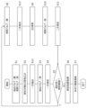
- the opening and closing operation of each valve will be explained in accordance with the flowchart of a specific measurement procedure example shown in Figure 8.
- "S" in the explanation of the flowchart means a step or process.
- the first valve 384 and the second valve 385 are open, and the dilution valve 383 is closed.
- the backwash pump and other components of the direction switching unit 35 are operated, and the depolymerization agent to be measured, such as EG, is taken from the tank body 31 into the depolymerization agent flow unit 32.
- the first cooling unit 361 and/or the second cooling unit 362 cool the taken-in depolymerization agent, such as EG, to a predetermined measurable temperature of the characteristic measuring unit 33.
- the depolymerization agent such as EG
- the first cooling unit 361 and/or the second cooling unit 362 enters the space between the first valve 384 and the second valve 385, which are open in S1.
- the first valve 384 and the second valve 385 are switched to a closed state.
- a closed space is temporarily formed between the first valve 384 and the second valve 385, and the total amount of BHET, etc. in the closed space is determined.
- the characteristic measurement unit 33 performs a primary measurement of the refractive index of the depolymerization agent such as EG in the closed space formed in S3.
- the progress monitoring unit 37 calculates the concentration of the depolymerization agent such as BHET based on the refractive index measurement result obtained in S6.
- the dilution valve 383 is switched to an open state.
- the second valve 385 is switched to an open state in order to guide the EG for dilution to the characteristic measurement unit 33.
- the backwash pump or the like constituting the direction switching unit 35 is operated, and the EG for dilution is supplied from the dilution depolymerization agent supply unit 381 through the open dilution valve 383 to the space between the first valve 384 and the second valve 385.
- the amount of EG used for dilution in S9 is measured by a flow sensor (not shown) provided in the dilution valve 383 or the like.
- the dilution valve 383 is switched to a closed state
- the second valve 385 is switched to a closed state, again forming a closed space between the first valve 384 and the second valve 385.
- the characteristic measurement unit 33 performs a secondary measurement of the refractive index of the depolymerization agent such as EG in the closed space formed in S3 and S10(2), and then returns to S5. If the judgment in S5 is "No," the refractive index after EG dilution measured in S11 falls within a linear range below the saturation threshold B, and is therefore adopted as the measurement result by the characteristic measurement unit 33 in S6.
- the progress monitoring unit 37 calculates the original (undiluted) concentration of BHET, etc. in the tank body 31 (the concentration on the "after dilution" line in Figure 7) based on the secondary measurement result of the refractive index within the linear range obtained in S11 and the amount of EG, etc.
- the dilution valve 383, the first valve 384, and the second valve 385 can control the amount of depolymerization agent such as EG that enters the closed space formed in S3 (the space defined by the three valves) from the tank body 31 and the diluted depolymerization agent supply unit 381, respectively, so the progress monitoring unit 37 can calculate the concentration of BHET, etc. in the tank body 31 while grasping the quantitative effect of dilution by the depolymerization agent dilution unit 38.
- the amount of dilution EG etc. supplied by the dilution depolymerization agent supply unit 381 can also be controlled.
- the temperature can also be controlled.
- the EG etc. in the closed space can be cooled to a predetermined measurable temperature of the characteristic measurement unit 33.
- at least part of the function of the cooling unit 36 can be realized by the dilution EG etc. supplied by the dilution depolymerization agent supply unit 381.
- at least part of the first cooling unit 361 and the second cooling unit 362 in FIG. 6 do not need to be provided.
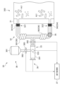
- FIG. 9 shows a third embodiment of a depolymerization reaction monitoring device 30 according to the present invention. Configurations similar to those of the first embodiment in FIG. 4 and/or the second embodiment in FIG. 6 are given the same reference numerals and redundant explanations are omitted.
- the depolymerization agent flow section 32 is provided with an extraction section 39 capable of extracting a specified amount from the depolymerization agent such as EG flowing therethrough.
- the extraction section 39 includes, for example, a syringe pump 391 and an extraction valve 392.
- the syringe pump 391 extracts, takes in, or discharges the depolymerization agent such as EG depending on the position of a movable piston housed therein.
- the extraction valve 392 is provided between the main body of the tubular depolymerization agent flow section 32 and the syringe pump 391.
- the extraction section 39 may include other types of pumps instead of the syringe pump 391.
- a gear pump, a suction pump, a plunger pump, or a vane pump may be provided in the extraction section 39 instead of the syringe pump 391.
- the characteristic measuring unit 33 is provided in the syringe pump 391. Specifically, as shown in the schematic diagram, the optical measurement described above is performed through a window 333 provided in the syringe pump 391 (illustration of the light source 331 and the light receiving unit 332 is omitted). Such a characteristic measuring unit 33 measures the characteristics of the depolymerization agent such as EG extracted by the extraction unit 39 (syringe pump 391).
- the depolymerization agent flow section 32 is provided with a depolymerization agent dilution section 38 that further dilutes the depolymerization agent such as EG extracted by the extraction section 39 (syringe pump 391) by adding a depolymerization agent such as EG.
- the characteristic measurement section 33 measures the characteristics of the depolymerization agent such as EG diluted by the depolymerization agent dilution section 38.
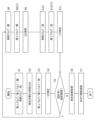
- FIG. 10 is a flow chart of a specific example of the measurement procedure. Steps or processes similar to those in FIG. 8 in the second embodiment are given the same reference numerals, and duplicated explanations are omitted.
- the extraction valve 392 is open and the dilution valve 383 is closed.
- the backwash pump and other components of the direction switching unit 35 are operated to take in the depolymerization agent such as EG to be measured from the tank body 31 into the depolymerization agent flow unit 32.
- the extraction unit 39 extracts (primary extraction) a specified amount (first specified amount) of the depolymerization agent such as EG taken in to the depolymerization agent flow unit 32 in S2.
- the extraction valve 392 is switched to a closed state. As a result, the first specified amount of depolymerization agent such as EG is secured in the extraction unit 39 (syringe pump 391).
- the characteristic measurement unit 33 performs a primary measurement of the refractive index of the first specified amount of depolymerization agent such as EG secured in the extraction unit 39 (syringe pump 391) in S3.
- the progress monitoring unit 37 calculates the concentration of the depolymerization agent such as BHET based on the refractive index measurement result obtained in S6.
- the dilution valve 383 is switched to an open state.
- the extraction unit 39 extracts (secondarily extracts) a specified amount (second specified amount) of EG for dilution from the dilution depolymerization agent supply unit 381 through the open dilution valve 383.
- the EG in the extraction unit 39 (syringe pump 391) is diluted with the EG for dilution extracted in S13.
- the dilution valve 383 is switched to a closed state.
- the second specified amount of depolymerization agent such as EG in which depolymerization polymers such as BHET are not dissolved is secured in the extraction section 39 (syringe pump 391).
- the characteristic measurement unit 33 performs a secondary measurement of the refractive index of the depolymerization agent such as EG in the first specified amount and the second specified amount secured in the extraction unit 39 (syringe pump 391) in S3 and S10, and returns to S5. If the judgment in S5 is "No", the refractive index after EG dilution measured in S11 is within the linear range below the saturation threshold B, so it is adopted as the measurement result by the characteristic measurement unit 33 in S6. In S7, the progress monitoring unit 37 calculates the original (undiluted) concentration of BHET, etc. in the tank body 31 (the concentration on the "diluted" line in FIG.
- the syringe pump 391, extraction valve 392, and dilution valve 383 can control the amount of depolymerization agent such as EG that enters the extraction section 39 (syringe pump 391) from the tank body 31 (or depolymerization agent flow section 32) and the diluted depolymerization agent supply section 381, respectively, so the progress monitoring section 37 can calculate the concentration of BHET, etc. in the tank body 31 while grasping the quantitative effect of dilution by the depolymerization agent dilution section 38.
- depolymerization agent such as EG that enters the extraction section 39 (syringe pump 391) from the tank body 31 (or depolymerization agent flow section 32) and the diluted depolymerization agent supply section 381, respectively
- each device and method described in the embodiments can be realized by hardware resources or software resources, or by the cooperation of hardware resources and software resources.
- a processor, ROM, RAM, and various integrated circuits can be used as hardware resources.
- an operating system, application programs, and the like can be used as software resources.
- the present invention relates to a depolymerization reaction monitoring device, etc.
- Injection molding machine 30. Depolymerization reaction monitoring device, 31. Tank body, 32. Depolymerization material circulation section, 33. Characteristics measurement section, 34. Intrusion prevention section, 35. Direction switching section, 36. Cooling section, 37. Progress monitoring section, 38. Depolymerization material dilution section, 39. Extraction section, 100. Chemical recycling device, 300. Depolymerization reaction tank, 321. One end, 322. Other end, 331. Light source, 332. Light receiving section, 333. Window, 341. First filter, 342. Second filter, 361. First cooling section, 362. Second cooling section, 381. Diluted depolymerization material supply section, 382. Dilution pipe, 383. Dilution valve, 384. First valve, 385. Second valve, 391. Syringe pump, 392. Extraction valve.
Landscapes
- Chemical & Material Sciences (AREA)
- Organic Chemistry (AREA)
- Chemical Kinetics & Catalysis (AREA)
- Life Sciences & Earth Sciences (AREA)
- Sustainable Development (AREA)
- Health & Medical Sciences (AREA)
- Medicinal Chemistry (AREA)
- Polymers & Plastics (AREA)
- Polyesters Or Polycarbonates (AREA)
- Separation, Recovery Or Treatment Of Waste Materials Containing Plastics (AREA)
Priority Applications (4)
| Application Number | Priority Date | Filing Date | Title |
|---|---|---|---|
| JP2024562616A JPWO2024122208A1 (https=) | 2022-12-08 | 2023-10-24 | |
| DE112023005114.3T DE112023005114T5 (de) | 2022-12-08 | 2023-10-24 | Depolymerisationsreaktions-überwachungsvorrichtung, depolymerisationsreaktions-überwachungsverfahren und depolymerisationsreaktions-überwachungsprogramm |
| CN202380071662.5A CN119998376A (zh) | 2022-12-08 | 2023-10-24 | 解聚反应监视装置、解聚反应监视方法及解聚反应监视程序 |
| US19/201,959 US20250277097A1 (en) | 2022-12-08 | 2025-05-08 | Depolymerization reaction monitoring device, depolymerization reaction monitoring method, and depolymerization reaction monitoring program |
Applications Claiming Priority (2)
| Application Number | Priority Date | Filing Date | Title |
|---|---|---|---|
| JP2022196415 | 2022-12-08 | ||
| JP2022-196415 | 2022-12-08 |
Related Child Applications (1)
| Application Number | Title | Priority Date | Filing Date |
|---|---|---|---|
| US19/201,959 Continuation US20250277097A1 (en) | 2022-12-08 | 2025-05-08 | Depolymerization reaction monitoring device, depolymerization reaction monitoring method, and depolymerization reaction monitoring program |
Publications (1)
| Publication Number | Publication Date |
|---|---|
| WO2024122208A1 true WO2024122208A1 (ja) | 2024-06-13 |
Family
ID=91378881
Family Applications (1)
| Application Number | Title | Priority Date | Filing Date |
|---|---|---|---|
| PCT/JP2023/038254 Ceased WO2024122208A1 (ja) | 2022-12-08 | 2023-10-24 | 解重合反応監視装置、解重合反応監視方法、解重合反応監視プログラム |
Country Status (5)
| Country | Link |
|---|---|
| US (1) | US20250277097A1 (https=) |
| JP (1) | JPWO2024122208A1 (https=) |
| CN (1) | CN119998376A (https=) |
| DE (1) | DE112023005114T5 (https=) |
| WO (1) | WO2024122208A1 (https=) |
Cited By (1)
| Publication number | Priority date | Publication date | Assignee | Title |
|---|---|---|---|---|
| WO2025052957A1 (ja) * | 2023-09-05 | 2025-03-13 | 住友重機械工業株式会社 | 反応監視装置、反応監視方法、反応監視プログラム |
Citations (3)
| Publication number | Priority date | Publication date | Assignee | Title |
|---|---|---|---|---|
| US20120223270A1 (en) * | 2011-03-04 | 2012-09-06 | King Abdulaziz City For Science And Technology | Methods of depolymerizing terephthalate polyesters |
| JP2016536291A (ja) * | 2013-10-15 | 2016-11-24 | インターナショナル・ビジネス・マシーンズ・コーポレーションInternational Business Machines Corporation | ポリエステルを解重合する方法 |
| JP2022101632A (ja) * | 2016-07-12 | 2022-07-06 | キャルビオス | 新規エステラーゼ及びその使用 |
-
2023
- 2023-10-24 JP JP2024562616A patent/JPWO2024122208A1/ja active Pending
- 2023-10-24 DE DE112023005114.3T patent/DE112023005114T5/de active Pending
- 2023-10-24 WO PCT/JP2023/038254 patent/WO2024122208A1/ja not_active Ceased
- 2023-10-24 CN CN202380071662.5A patent/CN119998376A/zh active Pending
-
2025
- 2025-05-08 US US19/201,959 patent/US20250277097A1/en active Pending
Patent Citations (3)
| Publication number | Priority date | Publication date | Assignee | Title |
|---|---|---|---|---|
| US20120223270A1 (en) * | 2011-03-04 | 2012-09-06 | King Abdulaziz City For Science And Technology | Methods of depolymerizing terephthalate polyesters |
| JP2016536291A (ja) * | 2013-10-15 | 2016-11-24 | インターナショナル・ビジネス・マシーンズ・コーポレーションInternational Business Machines Corporation | ポリエステルを解重合する方法 |
| JP2022101632A (ja) * | 2016-07-12 | 2022-07-06 | キャルビオス | 新規エステラーゼ及びその使用 |
Cited By (1)
| Publication number | Priority date | Publication date | Assignee | Title |
|---|---|---|---|---|
| WO2025052957A1 (ja) * | 2023-09-05 | 2025-03-13 | 住友重機械工業株式会社 | 反応監視装置、反応監視方法、反応監視プログラム |
Also Published As
| Publication number | Publication date |
|---|---|
| JPWO2024122208A1 (https=) | 2024-06-13 |
| DE112023005114T5 (de) | 2025-10-16 |
| CN119998376A (zh) | 2025-05-13 |
| US20250277097A1 (en) | 2025-09-04 |
Similar Documents
| Publication | Publication Date | Title |
|---|---|---|
| US11518865B2 (en) | Process for reclamation of polyester by reactor addition | |
| EP3853298B1 (en) | Process and system for depolymerizing plastic | |
| US20250277097A1 (en) | Depolymerization reaction monitoring device, depolymerization reaction monitoring method, and depolymerization reaction monitoring program | |
| EP2021116B1 (de) | Verfahren und vorrichtung zur wiederverwertung von polyestermaterial | |
| CA1118570A (en) | Process for manufacturing shaped polyester article using scrap materials | |
| WO2025052957A1 (ja) | 反応監視装置、反応監視方法、反応監視プログラム | |
| KR101898308B1 (ko) | 폴리카보네이트 수지의 제조 방법 | |
| US20250122141A1 (en) | Chemical recycling device and chemical recycling molding system | |
| JP7720173B2 (ja) | モノマー製造システム及びモノマー製造方法 | |
| US20240287248A1 (en) | Production of recycled polyesters from polyester waste through chemical recycling methodology | |
| KR20150105781A (ko) | 폴리에스터 폐기물의 재생장치 | |
| US12570793B2 (en) | Process for formation of additive-containing polyester | |
| WO2025013529A1 (ja) | リサイクルシステム、リサイクル方法、記憶媒体 | |
| US20170226284A1 (en) | Method of preparing polyalkylene carbonate resin | |
| WO2024202715A1 (ja) | 重合体撹拌装置、リサイクルシステム | |
| WO2025013530A1 (ja) | リサイクルシステム、リサイクル方法、記憶媒体 | |
| CN113637117B (zh) | 由hips生产方法切换至gpps生产方法的切换方法 | |
| He et al. | An Integrated Process for Closed-Loop Recycling of PET waste: From Depolymerization and Monomer Purification to Recycled PET (rPET) Production | |
| Salazar‐Sánchez et al. | Glycolytic Depolymerization of Green Poly (Ethylene Terephthalate)(PET) via Reactive Extrusion Toward BHET Recovery | |
| CN217516872U (zh) | 一种由废旧聚酯制备再生聚酯的连续化生产系统 | |
| Al-Sabagh et al. | Ionic liquids as Efficient Catalysts for The Glycolysis of Polyethylene Terephthalate | |
| JP6089626B2 (ja) | ポリカーボネートの製造方法 | |
| JP2025184014A (ja) | 重合システム、重合体の製造方法、ケミカルリサイクルシステム | |
| CA3255931A1 (en) | METHOD AND APPARATUS FOR INCREASING THE INTRINSIC VISCOSITY OF POLYCONDENSES | |
| WO2024143102A1 (ja) | プリフォームの製造方法 |
Legal Events
| Date | Code | Title | Description |
|---|---|---|---|
| 121 | Ep: the epo has been informed by wipo that ep was designated in this application |
Ref document number: 23900330 Country of ref document: EP Kind code of ref document: A1 |
|
| WWE | Wipo information: entry into national phase |
Ref document number: 2024562616 Country of ref document: JP |
|
| WWE | Wipo information: entry into national phase |
Ref document number: 202380071662.5 Country of ref document: CN |
|
| WWP | Wipo information: published in national office |
Ref document number: 202380071662.5 Country of ref document: CN |
|
| WWE | Wipo information: entry into national phase |
Ref document number: 112023005114 Country of ref document: DE |
|
| WWP | Wipo information: published in national office |
Ref document number: 112023005114 Country of ref document: DE |
|
| 122 | Ep: pct application non-entry in european phase |
Ref document number: 23900330 Country of ref document: EP Kind code of ref document: A1 |