WO2024122196A1 - 位置判定装置、位置判定システム、無線通信モジュール、コンピュータプログラム - Google Patents
位置判定装置、位置判定システム、無線通信モジュール、コンピュータプログラム Download PDFInfo
- Publication number
- WO2024122196A1 WO2024122196A1 PCT/JP2023/037569 JP2023037569W WO2024122196A1 WO 2024122196 A1 WO2024122196 A1 WO 2024122196A1 JP 2023037569 W JP2023037569 W JP 2023037569W WO 2024122196 A1 WO2024122196 A1 WO 2024122196A1
- Authority
- WO
- WIPO (PCT)
- Prior art keywords
- communication
- portable device
- distance
- vehicle
- communication unit
- Prior art date
- Legal status (The legal status is an assumption and is not a legal conclusion. Google has not performed a legal analysis and makes no representation as to the accuracy of the status listed.)
- Ceased
Links
Images


Classifications
-
- G—PHYSICS
- G01—MEASURING; TESTING
- G01S—RADIO DIRECTION-FINDING; RADIO NAVIGATION; DETERMINING DISTANCE OR VELOCITY BY USE OF RADIO WAVES; LOCATING OR PRESENCE-DETECTING BY USE OF THE REFLECTION OR RERADIATION OF RADIO WAVES; ANALOGOUS ARRANGEMENTS USING OTHER WAVES
- G01S13/00—Systems using the reflection or reradiation of radio waves, e.g. radar systems; Analogous systems using reflection or reradiation of waves whose nature or wavelength is irrelevant or unspecified
- G01S13/74—Systems using reradiation of radio waves, e.g. secondary radar systems; Analogous systems
- G01S13/82—Systems using reradiation of radio waves, e.g. secondary radar systems; Analogous systems wherein continuous-type signals are transmitted
- G01S13/84—Systems using reradiation of radio waves, e.g. secondary radar systems; Analogous systems wherein continuous-type signals are transmitted for distance determination by phase measurement
-
- G—PHYSICS
- G01—MEASURING; TESTING
- G01S—RADIO DIRECTION-FINDING; RADIO NAVIGATION; DETERMINING DISTANCE OR VELOCITY BY USE OF RADIO WAVES; LOCATING OR PRESENCE-DETECTING BY USE OF THE REFLECTION OR RERADIATION OF RADIO WAVES; ANALOGOUS ARRANGEMENTS USING OTHER WAVES
- G01S7/00—Details of systems according to groups G01S13/00, G01S15/00, G01S17/00
- G01S7/003—Transmission of data between radar, sonar or lidar systems and remote stations
- G01S7/006—Transmission of data between radar, sonar or lidar systems and remote stations using shared front-end circuitry, e.g. antennas
-
- G—PHYSICS
- G01—MEASURING; TESTING
- G01S—RADIO DIRECTION-FINDING; RADIO NAVIGATION; DETERMINING DISTANCE OR VELOCITY BY USE OF RADIO WAVES; LOCATING OR PRESENCE-DETECTING BY USE OF THE REFLECTION OR RERADIATION OF RADIO WAVES; ANALOGOUS ARRANGEMENTS USING OTHER WAVES
- G01S11/00—Systems for determining distance or velocity not using reflection or reradiation
- G01S11/02—Systems for determining distance or velocity not using reflection or reradiation using radio waves
-
- G—PHYSICS
- G01—MEASURING; TESTING
- G01S—RADIO DIRECTION-FINDING; RADIO NAVIGATION; DETERMINING DISTANCE OR VELOCITY BY USE OF RADIO WAVES; LOCATING OR PRESENCE-DETECTING BY USE OF THE REFLECTION OR RERADIATION OF RADIO WAVES; ANALOGOUS ARRANGEMENTS USING OTHER WAVES
- G01S13/00—Systems using the reflection or reradiation of radio waves, e.g. radar systems; Analogous systems using reflection or reradiation of waves whose nature or wavelength is irrelevant or unspecified
- G01S13/74—Systems using reradiation of radio waves, e.g. secondary radar systems; Analogous systems
- G01S13/76—Systems using reradiation of radio waves, e.g. secondary radar systems; Analogous systems wherein pulse-type signals are transmitted
- G01S13/765—Systems using reradiation of radio waves, e.g. secondary radar systems; Analogous systems wherein pulse-type signals are transmitted with exchange of information between interrogator and responder
-
- G—PHYSICS
- G01—MEASURING; TESTING
- G01S—RADIO DIRECTION-FINDING; RADIO NAVIGATION; DETERMINING DISTANCE OR VELOCITY BY USE OF RADIO WAVES; LOCATING OR PRESENCE-DETECTING BY USE OF THE REFLECTION OR RERADIATION OF RADIO WAVES; ANALOGOUS ARRANGEMENTS USING OTHER WAVES
- G01S13/00—Systems using the reflection or reradiation of radio waves, e.g. radar systems; Analogous systems using reflection or reradiation of waves whose nature or wavelength is irrelevant or unspecified
- G01S13/88—Radar or analogous systems specially adapted for specific applications
- G01S13/93—Radar or analogous systems specially adapted for specific applications for anti-collision purposes
- G01S13/931—Radar or analogous systems specially adapted for specific applications for anti-collision purposes of land vehicles
-
- G—PHYSICS
- G01—MEASURING; TESTING
- G01S—RADIO DIRECTION-FINDING; RADIO NAVIGATION; DETERMINING DISTANCE OR VELOCITY BY USE OF RADIO WAVES; LOCATING OR PRESENCE-DETECTING BY USE OF THE REFLECTION OR RERADIATION OF RADIO WAVES; ANALOGOUS ARRANGEMENTS USING OTHER WAVES
- G01S5/00—Position-fixing by co-ordinating two or more direction or position line determinations; Position-fixing by co-ordinating two or more distance determinations
- G01S5/01—Determining conditions which influence positioning, e.g. radio environment, state of motion or energy consumption
-
- G—PHYSICS
- G01—MEASURING; TESTING
- G01S—RADIO DIRECTION-FINDING; RADIO NAVIGATION; DETERMINING DISTANCE OR VELOCITY BY USE OF RADIO WAVES; LOCATING OR PRESENCE-DETECTING BY USE OF THE REFLECTION OR RERADIATION OF RADIO WAVES; ANALOGOUS ARRANGEMENTS USING OTHER WAVES
- G01S5/00—Position-fixing by co-ordinating two or more direction or position line determinations; Position-fixing by co-ordinating two or more distance determinations
- G01S5/02—Position-fixing by co-ordinating two or more direction or position line determinations; Position-fixing by co-ordinating two or more distance determinations using radio waves
- G01S5/0257—Hybrid positioning
- G01S5/0263—Hybrid positioning by combining or switching between positions derived from two or more separate positioning systems
-
- G—PHYSICS
- G01—MEASURING; TESTING
- G01S—RADIO DIRECTION-FINDING; RADIO NAVIGATION; DETERMINING DISTANCE OR VELOCITY BY USE OF RADIO WAVES; LOCATING OR PRESENCE-DETECTING BY USE OF THE REFLECTION OR RERADIATION OF RADIO WAVES; ANALOGOUS ARRANGEMENTS USING OTHER WAVES
- G01S5/00—Position-fixing by co-ordinating two or more direction or position line determinations; Position-fixing by co-ordinating two or more distance determinations
- G01S5/02—Position-fixing by co-ordinating two or more direction or position line determinations; Position-fixing by co-ordinating two or more distance determinations using radio waves
- G01S5/14—Determining absolute distances from a plurality of spaced points of known location
-
- H—ELECTRICITY
- H04—ELECTRIC COMMUNICATION TECHNIQUE
- H04W—WIRELESS COMMUNICATION NETWORKS
- H04W4/00—Services specially adapted for wireless communication networks; Facilities therefor
- H04W4/02—Services making use of location information
- H04W4/023—Services making use of location information using mutual or relative location information between multiple location based services [LBS] targets or of distance thresholds
-
- H—ELECTRICITY
- H04—ELECTRIC COMMUNICATION TECHNIQUE
- H04W—WIRELESS COMMUNICATION NETWORKS
- H04W4/00—Services specially adapted for wireless communication networks; Facilities therefor
- H04W4/30—Services specially adapted for particular environments, situations or purposes
- H04W4/40—Services specially adapted for particular environments, situations or purposes for vehicles, e.g. vehicle-to-pedestrians [V2P]
-
- H—ELECTRICITY
- H04—ELECTRIC COMMUNICATION TECHNIQUE
- H04W—WIRELESS COMMUNICATION NETWORKS
- H04W52/00—Power management, e.g. Transmission Power Control [TPC] or power classes
- H04W52/02—Power saving arrangements
- H04W52/0209—Power saving arrangements in terminal devices
- H04W52/0225—Power saving arrangements in terminal devices using monitoring of external events, e.g. the presence of a signal
- H04W52/0229—Power saving arrangements in terminal devices using monitoring of external events, e.g. the presence of a signal where the received signal is a wanted signal
-
- H—ELECTRICITY
- H04—ELECTRIC COMMUNICATION TECHNIQUE
- H04W—WIRELESS COMMUNICATION NETWORKS
- H04W52/00—Power management, e.g. Transmission Power Control [TPC] or power classes
- H04W52/02—Power saving arrangements
- H04W52/0209—Power saving arrangements in terminal devices
- H04W52/0225—Power saving arrangements in terminal devices using monitoring of external events, e.g. the presence of a signal
- H04W52/0245—Power saving arrangements in terminal devices using monitoring of external events, e.g. the presence of a signal according to signal strength
-
- H—ELECTRICITY
- H04—ELECTRIC COMMUNICATION TECHNIQUE
- H04W—WIRELESS COMMUNICATION NETWORKS
- H04W52/00—Power management, e.g. Transmission Power Control [TPC] or power classes
- H04W52/02—Power saving arrangements
- H04W52/0209—Power saving arrangements in terminal devices
- H04W52/0261—Power saving arrangements in terminal devices managing power supply demand, e.g. depending on battery level
- H04W52/0274—Power saving arrangements in terminal devices managing power supply demand, e.g. depending on battery level by switching on or off the equipment or parts thereof
- H04W52/028—Power saving arrangements in terminal devices managing power supply demand, e.g. depending on battery level by switching on or off the equipment or parts thereof switching on or off only a part of the equipment circuit blocks
-
- G—PHYSICS
- G01—MEASURING; TESTING
- G01S—RADIO DIRECTION-FINDING; RADIO NAVIGATION; DETERMINING DISTANCE OR VELOCITY BY USE OF RADIO WAVES; LOCATING OR PRESENCE-DETECTING BY USE OF THE REFLECTION OR RERADIATION OF RADIO WAVES; ANALOGOUS ARRANGEMENTS USING OTHER WAVES
- G01S2205/00—Position-fixing by co-ordinating two or more direction or position line determinations; Position-fixing by co-ordinating two or more distance determinations
- G01S2205/01—Position-fixing by co-ordinating two or more direction or position line determinations; Position-fixing by co-ordinating two or more distance determinations specially adapted for specific applications
-
- G—PHYSICS
- G01—MEASURING; TESTING
- G01S—RADIO DIRECTION-FINDING; RADIO NAVIGATION; DETERMINING DISTANCE OR VELOCITY BY USE OF RADIO WAVES; LOCATING OR PRESENCE-DETECTING BY USE OF THE REFLECTION OR RERADIATION OF RADIO WAVES; ANALOGOUS ARRANGEMENTS USING OTHER WAVES
- G01S5/00—Position-fixing by co-ordinating two or more direction or position line determinations; Position-fixing by co-ordinating two or more distance determinations
- G01S5/02—Position-fixing by co-ordinating two or more direction or position line determinations; Position-fixing by co-ordinating two or more distance determinations using radio waves
- G01S5/0284—Relative positioning
-
- Y—GENERAL TAGGING OF NEW TECHNOLOGICAL DEVELOPMENTS; GENERAL TAGGING OF CROSS-SECTIONAL TECHNOLOGIES SPANNING OVER SEVERAL SECTIONS OF THE IPC; TECHNICAL SUBJECTS COVERED BY FORMER USPC CROSS-REFERENCE ART COLLECTIONS [XRACs] AND DIGESTS
- Y02—TECHNOLOGIES OR APPLICATIONS FOR MITIGATION OR ADAPTATION AGAINST CLIMATE CHANGE
- Y02D—CLIMATE CHANGE MITIGATION TECHNOLOGIES IN INFORMATION AND COMMUNICATION TECHNOLOGIES [ICT], I.E. INFORMATION AND COMMUNICATION TECHNOLOGIES AIMING AT THE REDUCTION OF THEIR OWN ENERGY USE
- Y02D30/00—Reducing energy consumption in communication networks
- Y02D30/70—Reducing energy consumption in communication networks in wireless communication networks
Definitions
- This disclosure relates to technology for determining the position of a mobile device relative to a vehicle by wirelessly communicating with the mobile device.
- Patent Document 1 discloses a configuration in which, in an in-vehicle system including one parent unit and multiple child units, the parent unit detects the presence of a portable device near the vehicle based on the reception strength of a signal emitted from the portable device and activates the child units.
- the parent unit and child units are communication devices that perform wireless communication with a portable terminal.
- the communication module corresponding to the child device is not activated and remains in a stopped state until the communication module serving as the parent device detects the mobile device. This is expected to have the effect of reducing power consumption during standby (e.g., while parked).
- the developers of this disclosure have furthered their investigations into a configuration in which the parent device returns the target device from power saving mode to normal mode (i.e., activates it) when the reception strength of the signal from the mobile device reaches or exceeds a predetermined value.
- the target device is not limited to a child device, and may be any device.
- BLE Bluetooth Low Energy
- the target device may be a variety of devices/modules, such as a computer, a communication module, or a circuit module.
- the present disclosure has been made based on the above considerations and points of view, and one of its objectives is to provide a position determination device, a position determination system, a wireless communication module, and a computer program that can reduce power consumption during standby.
- the position determination device disclosed herein is a position determination device that determines the position of a portable device relative to a vehicle, and includes a first communication unit that performs wireless communication with the portable device in accordance with Bluetooth, and a computer that performs processing related to determining the position of the portable device, the computer having a normal mode and a power saving mode as states, the first communication unit being set to maintain a state in which communication with the portable device is possible even while the computer is in the power saving mode, the first communication unit executes a first ranging process that calculates a first distance, which is the distance from the first communication unit to the portable device, using data related to the reception phase, flight time, or arrival time of a wireless signal transmitted from the portable device, the first communication unit compares the first distance obtained as a result of the first ranging process with a predetermined value, and transitions the computer from the power saving mode to the normal mode based on the comparison result.
- a first ranging process that calculates a first distance, which is the distance from the first communication unit to the portable device,
- the condition for returning the computer to normal mode is that the first distance, which is determined based on a parameter corresponding to the signal propagation time, such as the reception phase or arrival time of the wireless signal transmitted from the portable device, falls below a predetermined value.
- a first distance has smaller distance measurement errors due to the communication environment than reception strength. Therefore, with the above configuration, it is possible to reduce the risk of starting the computer when it is not necessary to start it, such as when the portable device is far from the vehicle. As a result, it is also possible to reduce power consumption during standby.
- the position determination system included in the present disclosure is a position determination system including a first communication unit that performs wireless communication with a portable device in accordance with Bluetooth, and a computer that performs processing related to position determination of the portable device, the computer having a normal mode and a power saving mode as states, the first communication unit performs a first ranging process that calculates a first distance, which is the distance from the first communication unit to the portable device, using the reception phase, flight time, or arrival time of a wireless signal transmitted from the portable device when the computer is in the power saving mode, the first communication unit compares the first distance obtained as a result of the first ranging process with a predetermined value, and returns the computer from the power saving mode to the normal mode based on the comparison result.
- the above-mentioned position determination system also has a similar configuration to the above-mentioned position determination device. Therefore, the above-mentioned system also makes it possible to reduce power consumption during standby.
- the wireless communication module included in the present disclosure is a wireless communication module that performs wireless communication with a portable device in accordance with Bluetooth, and includes an antenna for communicating with the portable device, and a communication controller that acquires data related to the reception phase, flight time, or arrival time of a wireless signal transmitted from the portable device based on a signal received by the antenna, and the communication controller maintains a state in which communication with the portable device is possible even while the vehicle is parked based on power from a battery installed in the vehicle, and when the vehicle is parked, executes a first distance measurement process that calculates a first distance, which is the distance from the vehicle to the portable device, using data related to the reception phase, flight time, or arrival time of the wireless signal, and compares the first distance obtained as a result of the first distance measurement process with a predetermined value, and outputs a signal to transition a predetermined target device installed in the vehicle from a power saving mode to a normal mode based on the comparison result.
- the wireless communication module also makes it possible to reduce power consumption during standby for the same reasons as the position determination device.
- the computer program included in the present disclosure includes instructions to cause a processor of a portable device equipped with a Bluetooth communication unit for performing wireless communication compliant with Bluetooth and a UWB communication unit for performing ultra-wideband (UWB) communication to perform the following: establish a communication connection with the vehicle via Bluetooth based on receiving a signal emitted from a vehicle to which the portable device is previously linked, return a signal for ranging processing based on receiving a request to start a first ranging processing, which is ranging processing via Bluetooth communication, from the vehicle, transmit continuous wave signals of different frequencies in sequence after returning the signal for ranging processing, activate the UWB communication unit when a request to start a second ranging processing, which is ranging processing via UWB communication, is received from the vehicle, and return a UWB signal of a predetermined pattern when a UWB signal for ranging is received from the vehicle.
- the above computer program is a computer program for causing a normal device to function as a portable device that responds to a position determination device/position determination system. Furthermore, according to the above computer program, the operation of the UWB communication unit in the portable device can be stopped if a request to start the second ranging process from the vehicle is not received, thereby reducing power consumption during standby.
- FIG. 1 is a diagram showing an overall view of a vehicle electronic key system.
- FIG. 2 is a block diagram showing a configuration of a portable device.
- FIG. 2 is a block diagram showing the configuration of a DK-ECU.
- FIG. 2 is a block diagram showing the configuration of a BLE module.
- FIG. 13 is a diagram illustrating a flow of a CS ranging process.
- FIG. 2 is a functional block diagram of a main controller.
- 5 is a flowchart for explaining the operation of the DK-ECU when the main controller is in a power saving mode.
- 5 is a flowchart for explaining the operation of the DK-ECU when the main controller is in a normal mode.
- FIG. 4 is a flowchart for explaining the operation of the DK-ECU in response to a user's approach to the vehicle.
- 10 is a flowchart showing another example of the operation of the DK-ECU after the main controller is started up.
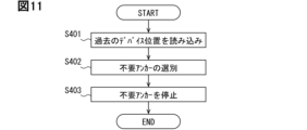
- 10 is a flowchart showing the operation of the main controller when selecting a UWB module to be used for the next location determination depending on the result of device location determination.
- FIG. 13 is a diagram for explaining an example of unnecessary anchors according to device positions.
- 11 is a flowchart illustrating another example of the operation of the BLE controller in a situation where the main controller is in a power saving mode.
- 11 is a flowchart illustrating another example of the operation of the BLE controller in a situation where the main controller is in a power saving mode.
- FIG. 11 is a flowchart illustrating another example of the operation of the BLE controller in a situation where the main controller is in a power saving mode.
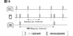
- 11 is a diagram for explaining the operation of the in-vehicle system and the portable device in a first waiting state.
- FIG. 11 is a diagram for explaining the operation of the in-vehicle system and the portable device in a second waiting state.
- FIG. 13 is a diagram for explaining the operation of the in-vehicle system and the portable device in a third waiting state.
- FIG. 13 is a diagram for explaining the operation of the in-vehicle system and the portable device in a position determination state.
- FIG. 13 is a block diagram showing another configuration example of the in-vehicle system.
- FIG. 13 is a block diagram showing another configuration example of the in-vehicle system.
- the electronic key system for a vehicle includes an in-vehicle system VS and a portable device 9.
- the in-vehicle system VS includes a digital key ECU (hereinafter referred to as DK-ECU) 1.
- ECU is an abbreviation for Electronic Control Unit, and refers to an electronic control device.
- DK is an abbreviation for digital key.
- the DK-ECU1 is configured to be able to perform wireless communication compliant with Bluetooth (registered trademark) Low Energy (hereinafter referred to as BLE communication) with a portable device 9 carried by the user of the vehicle Hv.
- BLE communication Bluetooth Low Energy
- master can be read as "central” or "scanner.”
- slave can be read as "peripheral” or "advertiser.”
- the DK-ECU1 establishes a communication connection with the portable device 9 by receiving an advertising signal from the portable device 9.
- the advertising signal is a BLE signal for notifying (i.e. advertising) its own presence to other devices.
- the BLE signal is a wireless signal that complies with BLE.
- the BLE signal may include a code indicating the sender or destination.
- the sender or destination may be expressed by a device ID or the like.
- the vehicle electronic key system may be configured so that the portable device 9 operates as a master in communication with the DK-ECU1, and the DK-ECU1 acts as a slave.
- the roles of each device are interchangeable.
- the functions and configurations of the DK-ECU1 and the portable device 9 may be changed as appropriate in accordance with the role exchange.
- a wireless signal that complies with the BLE standard is referred to as a BLE signal.
- an advertisement channel signal may be referred to as an advertisement signal
- a data channel signal may be referred to as a data signal.
- channels with channel numbers 37 to 39 correspond to advertisement channels.
- channels with channel numbers 0 to 36 correspond to data channels.
- the definitions and specific frequency values of advertisement channels and data channels are determined according to the BLE standard.
- the configuration of this disclosure may be modified as appropriate to comply with the modified standard.
- the in-vehicle system VS and the portable device 9 are also configured to be capable of UWB communication, which is wireless communication using the UWB-IR (Ultra Wide Band - Impulse Radio) method.
- the in-vehicle system VS and the portable device 9 are configured to be capable of transmitting and receiving impulse-shaped radio waves (hereinafter, impulse signals) used in UWB communication.
- impulse signals used in UWB communication is a signal that has an extremely short pulse width (e.g., 2 ns) and a bandwidth (i.e., ultra-wide bandwidth) of 500 MHz or more (strictly speaking, 499.2 MHz).
- the in-vehicle system VS is configured to communicate with the portable device 9 using the fifth channel of UWB communication.
- the in-vehicle system VS may be configured to be able to communicate with the portable device 9 using other channels, such as the third channel or the ninth channel.
- the third channel is a channel with a center frequency of 4492 MHz
- the fifth channel is a channel with a center frequency of 6489.6 MHz
- the ninth channel is a channel with a center frequency of 7987.2 MHz.
- IEEE registered trademark
- IEEE is an abbreviation for the Institute of Electrical and Electronics Engineers, which means the Institute of Electrical and Electronics Engineers.
- Each channel corresponds to a frequency band of ⁇ 250 MHz from the center frequency.
- Frequencies such as 3.1 GHz to 4.8 GHz and 6.0 GHz to 10.6 GHz can be used in UWB communication.
- the modulation method for UWB communication may be On Off Keying (OOK), Pulse Position Modulation (PPM), Pulse Width Modulation (PWM), etc.
- the modulation method may be MB-OFDM or DS-UWB.
- the On Off Modulation method is a method of expressing information by the presence/absence of an impulse signal.
- the Pulse Position Modulation method is a method of modulating at the position where a pulse is generated.
- the Pulse Width Modulation method is a method of expressing information by the pulse width.
- UWB communication between the in-vehicle system VS and the portable device 9 is performed by the OOK method.
- Data transmission by UWB communication is realized using multiple impulse signals.
- the data signal exchanged by UWB communication is referred to as a UWB signal. Since the UWB signal contains multiple impulses, it can also be called a pulse sequence signal.
- the portable device 9 is a portable and general-purpose information processing terminal equipped with a BLE communication function.
- the portable device 9 may be any communication terminal such as a smartphone or a wearable device.
- a wearable device is a device that is worn on a user's body when used.
- the wearable device may have various shapes such as a wristband type, a watch type, a finger ring type, a glasses type, an earphone type, etc.
- the portable device 9 may also be called a user device, a key device, etc.
- the portable device 9 may be a smart key, which is a dedicated device as an electronic key for the vehicle Hv.
- the smart key is a device that is transferred to the owner together with the vehicle Hv when the vehicle Hv is purchased.
- the smart key can be considered as one of the accessories of the vehicle Hv.
- the smart key may be in a variety of shapes, such as a flat rectangular parallelepiped type, a flat ellipsoid type (the so-called fob type), or a card type.
- the smart key may be called a vehicle portable device, a key fob, a key card, an access key, etc.
- the mobile device 9 includes a device control unit 90, a display 91, a touch panel 92, a BLE module 93, and a UWB module 94.
- the device control unit 90 is a module that controls the operation of the entire portable device 9.
- the device control unit 90 is configured as a computer equipped with a device processor 901, memory 902, storage 903, and input/output circuit 904.
- the device processor 901 may be a CPU (Central Processing Unit).
- the memory 902 is a volatile storage medium such as RAM (Random Access Memory).
- the storage 903 is configured to include a non-volatile storage medium such as a flash memory.
- Storage 903 may store a device ID and a key code used in wireless authentication processing with DK-ECU1.
- the key code may also be called an encryption key, etc.
- Storage 903 may have installed therein a digital key app, which is application software for causing the mobile device 9 to function as a vehicle key.
- the digital key app is an app for implementing secure communication with DK-ECU1 and responding to inquiries/requests from DK-ECU1.
- application software may be referred to simply as an app.
- the display 91 may be a liquid crystal display or an organic EL display.
- the display 91 displays an image according to an input signal from the device control unit 90.
- the touch panel 92 is a capacitive touch panel that is layered on the display 91.
- the touch panel 92 is an input device provided in the portable device 9.
- the touch panel 92 and the display 91 correspond to an interface that allows the user to input a password into the portable device 9 for logging in to the digital key app and for pairing the portable device 9 with the DK-ECU 1.
- the BLE module 93 is a communication module for performing BLE communication.
- the BLE module 93 has a strength detection unit, which is a functional unit that measures the reception strength of a received signal.
- the measured value of the reception strength itself may be called RSSI (Received Signal Strength Indicator/Indication).
- RSSI Receiveived Signal Strength Indicator/Indication
- the BLE module 93 transmits data indicating the measured reception strength together with source information to the device control unit 90.
- the BLE module 93 is configured to be capable of transmitting and receiving a continuous wave (CW) signal of a predetermined waveform as a signal for CS (Channel Sounding) ranging, which will be described later, in addition to a modulated signal for data communication.
- the CW signal may be a sine wave or a triangular wave.
- the BLE module 93 may have a similar configuration to the BLE module 12 provided in the in-vehicle system VS.
- the BLE module 93 may be configured in whole or in part as described above with respect to the BLE module 12.
- the BLE module 93 corresponds to a Bluetooth communication unit.
- the UWB module 94 is a communication module for performing UWB communication.
- the UWB module 94 outputs received data to the device control unit 90.
- the UWB module 94 also transmits a UWB signal corresponding to the transmission data based on instructions from the device control unit 90.
- the UWB module 94 may transmit a single impulse signal as a UWB signal for distance measurement based on instructions from the device control unit 90.
- the operation of the UWB module 94 is controlled by the device control unit 90.
- the UWB module 94 corresponds to a UWB communication unit.
- the device control unit 90 causes the BLE module 93 to transmit an advertising signal at a predetermined transmission interval. Furthermore, when the BLE module 93 receives a connection request from the DK-ECU1, it performs communication connection processing with the DK-ECU1. When the device control unit 90 receives a BLE signal transmitted from the vehicle Hv, it returns a response signal corresponding to the received signal. When the device control unit 90 has established a communication connection with the DK-ECU1, it may perform authentication processing by wireless communication (hereinafter, wireless authentication processing). The wireless authentication processing may be performed by a challenge-response method. When the device control unit 90 receives a challenge code from the DK-ECU1, it may generate a response code using the key code and return it to the DK-ECU1.
- wireless authentication processing may be performed by a challenge-response method.
- the device control unit 90 executes communication for distance measurement based on a request from the DK-ECU1. Based on a request from the DK-ECU1, the portable device 9 causes the BLE module 93 to transmit a CW signal on a specified channel.
- the interaction between the portable device 9 and the DK-ECU1 (actually the DK-ECU1) will be described separately below.
- the portable device 9 when the portable device 9 receives a UWB signal transmitted from the in-vehicle system VS, it returns a response signal corresponding to the received signal.
- the portable device 9 receives a UWB signal as a search signal, it returns a UWB signal modulated with a code including its own device ID to the in-vehicle system VS as a response signal.
- the search signal is a signal used by the in-vehicle system VS to search for the portable device 9, and is a type of signal that requests the portable device 9 to return a response signal.
- the UWB signals transmitted by the portable device 9 and the in-vehicle system VS may include a code indicating the sender or destination.
- the device control unit 90 maintains a standby state with respect to the BLE module 93 even when it is not connected for communication with the DK-ECU 1.
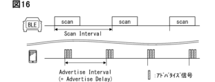
- the standby state is a state in which an advertising signal is transmitted periodically at a specified advertising interval.
- the standby state corresponds to a state in which an advertising state in which an advertising signal is being transmitted and a standby state in which an advertising signal is not being transmitted are alternately repeated.
- the device control unit 90 stops the UWB module 94. If a BLE link has been established with the DK-ECU1, the device control unit 90 starts the UWB module 94. This configuration reduces power consumption during standby.
- the device control unit 90 may be configured to start the UWB module 94 on the condition that a UWB ranging start request is received from the DK-ECU1 via BLE communication after establishing a BLE communication connection with the DK-ECU1.
- the UWB ranging start request is a BLE signal that requests the start of UWB ranging processing.
- the UWB module 94 often consumes more power than the BLE module 93. Therefore, by reducing the time that the UWB module 94 is activated, further power saving effects can be expected.
- the in-vehicle system VS includes a DK-ECU 1, a plurality of UWB modules 2, a body ECU 3, an action sensor 4, and an actuator 5.
- the DK-ECU 1 is individually connected to each of the plurality of UWB modules 2 by a cable.
- the DK-ECU 1 is also connected to the body ECU 3 via a dedicated communication cable or an in-vehicle network so that they can communicate with each other.
- the in-vehicle network is a communication network built in the vehicle Hv.
- the standard of the in-vehicle network may be any standard such as Controller Area Network (CAN: registered trademark), Ethernet (registered trademark), or FlexRay (registered trademark).
- the body ECU 3 is connected to the action sensor 4 and the actuator 5.
- the connection form between the devices disclosed here is only an example and can be changed as appropriate.
- the DK-ECU 1 is an ECU that determines the device position in cooperation with the UWB module 2.
- the device position means the relative position of the portable device 9 with respect to the vehicle Hv.
- the DK-ECU 1 determines whether or not the portable device 9 is present inside the vehicle based on the communication status between the multiple UWB modules 2 and the portable device 9.
- the DK-ECU 1 corresponds to a position determination device. Since the portable device 9 corresponds to a user, determining the device position corresponds to determining the user's position.
- the DK-ECU1 may be disposed in the instrument panel of the vehicle.
- the DK-ECU1 may also be attached to the overhead console, the right or left C-pillar, under the driver's seat, etc.
- the C-pillar refers to the third pillar from the front among the pillars equipped on the vehicle Hv.
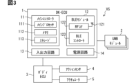
- the DK-ECU 1 comprises a main controller 11, a BLE module 12, an input/output circuit 13, and a power supply circuit 14.
- the main controller 11 is a computer that executes various processes related to determining the device position.
- the main controller 11 comprises a main processor 111, a memory 112, and a storage 113.
- the main processor 111 may be a CPU.
- the main processor 111 can be called an ECU processor, etc.
- the memory 112 is a volatile storage medium such as a RAM.
- Storage 113 includes a non-volatile storage medium such as a flash memory.
- a device location determination program executed by main processor 111 is stored in storage 113. Execution of the device location determination program by main processor 111 corresponds to execution of a location determination method corresponding to the device location determination program.
- the device ID of portable device 9 is also registered in storage 113. Additionally, data indicating the mounting position of each UWB module 2 in vehicle Hv is stored in storage 113.
- the main controller 11 has a normal mode and a power saving mode as power states, or in other words, operating modes (or in other words, states).
- the normal mode refers to a state in which power is supplied to the main controller 11 and various processes such as position determination can be executed.
- the power saving mode may be a so-called power-off state in which the power supply to the main controller 11 is completely cut off.
- the power saving mode may be a sleep mode or a hibernation mode.
- Sleep mode refers to a state in which the supply of power to the main processor 111 is stopped, with the data being worked on, in other words the execution state of the program, stored in a volatile memory such as a RAM.
- Hibernation refers to a state in which the supply of power to the main processor 111 and memory 112 is stopped, with the execution state of the program stored in a writable non-volatile memory such as a flash memory.
- the power saving mode may be referred to as a stop mode, since it is a state in which operation is stopped in one aspect.
- the power saving mode may be an operation mode that is activated intermittently at a low frequency, such as once every 10 seconds, 1 minute, or 10 minutes, and communicates with the body ECU 3 and an external server. Furthermore, the power saving mode may be a state in which functions are limited compared to the normal mode, in other words, an operation mode in which only some functions can be executed. The power saving mode may be a state in which the position determination function is stopped, while the authentication function by the backup means is maintained.
- the backup means refers to transponder communication or NFC (Near Field Communication), etc.
- the main controller 11 corresponds to a computer. Details of the main controller 11 will be described separately later.
- the BLE module 12 is a communication module for implementing BLE communication. Like the BLE module 93 provided in the mobile device 9, the BLE module 12 is configured to be capable of transmitting and receiving CW signals for each channel as signals for CS ranging, in addition to modulated signals for data communication.
- the BLE module 12 is supplied with power from the vehicle battery even while the driving power supply is set to off. Using the power supplied from the vehicle battery, the BLE module 12 is in a standby state either constantly or intermittently, even while the vehicle Hv is parked.
- the BLE module 12 periodically scans and attempts to connect to the portable device 9 even while the main controller 11 is in the power saving mode.
- the BLE module 12 executes a CS ranging process, described later, based on the communication connection with the portable device 9.
- the BLE module that maintains a state in which it can receive signals from the portable device 9 even while the main controller 11 is in the power saving mode is referred to as a gateway module in this disclosure.
- the gateway module can also be interpreted as a BLE module that plays a role in activating the main controller 11 based on the communication status with the portable device 9.
- the communication status here mainly includes the device distance and/or reception strength obtained as a CS ranging result.
- the device distance is the distance from a communication module mounted on the vehicle Hv, such as the BLE module 12 or the UWB module 2, to the portable device 9.
- the gateway module can also be interpreted as a BLE module that communicates and connects to the portable device 9. Details of the BLE module 12 will be described separately below.
- the BLE module 12 corresponds to a wireless communication module and a first communication unit.
- the input/output circuit 13 is a circuit module that enables the DK-ECU 1 to communicate with other devices such as the body ECU 3.
- the input/output circuit 13 may include analog circuit elements, ICs, and PHY chips that comply with in-vehicle network communication standards.
- the input/output circuit may also include chip sets that convert logical signals into actual electrical signals in interfaces such as CAN, Ethernet (registered trademark), and UART.
- the power supply circuit 14 is a circuit module that supplies power to each of the main controller 11, the BLE module 12, and the input/output circuit 13.
- the power supply circuit 14 converts the voltage (e.g., battery voltage) input from the power cable into a voltage suitable for the operation of each of the main controller 11, the BLE module 12, and the input/output circuit 13, and outputs it to each part.
- the power supply circuit 14 may have a function of switching the power supply of the DK-ECU1 from an OFF state to an ON state based on a predetermined start-up signal being input from the BLE module 12.
- the power OFF state of the DK-ECU1 corresponds to a state in which the power supply to components other than the power supply circuit 14 and the BLE module 12 is stopped.
- the power ON state of the DK-ECU1 corresponds to a state in which the main controller 11 is operating in normal mode.
- the main controller 11 cooperates with the power supply circuit 14 to transition to a power saving mode based on the driving power being set from ON to OFF.
- the UWB module 2 is a communication module for carrying out UWB communication. Like the UWB module 94 provided in the portable device 9, the UWB module 2 is configured to be able to transmit and receive UWB signals.
- the UWB module 2 is a communication device used to determine the position of the portable device 9, and is also called an anchor or a reference station.
- the UWB module 2 corresponds to the second communication unit.
- the UWB module 2 includes an antenna for UWB communications, a transmission/reception circuit, and a UWB controller.
- the transmission/reception circuit is a circuit that performs signal processing related to modulation and demodulation.
- the UWB controller is a microcomputer that controls the operation of the UWB module 2 and generates the UWB ranging data described below.
- the UWB module 2 performs UWB ranging processing based on instructions from the DK-ECU 1.
- the UWB ranging processing is a process for measuring the device distance based on the propagation time (in other words, the flight time) of radio waves from the UWB module 2 to the portable device 9.
- the UWB ranging processing includes a process for transmitting a UWB signal of a predetermined pattern toward the portable device 9, and a process for receiving a UWB signal as a response signal from the portable device 9.
- the UWB signal exchanged between the UWB module 2 and the portable device 9 may be a single impulse signal, or a pulse sequence signal in which multiple impulse signals are arranged in a predetermined pattern.
- the UWB ranging processing corresponds to the second ranging processing.
- the UWB controller measures the round trip time (RTT), which is the time elapsed from transmitting a UWB signal to receiving a response signal from the portable device 9, and calculates the device distance based on the RTT.
- the RTT corresponds to the round trip flight time of the UWB signal.
- the RTT takes a value according to the distance from the UWB module 2 to the portable device 9.
- the UWB controller of this embodiment calculates the device distance by multiplying half the value obtained by subtracting a predetermined correction value from the RTT by the propagation time of the radio waves.
- the correction value here is a parameter for offsetting the response processing time in the portable device 9 and the delay time within the UWB module 2.
- the specific value of the correction value can be designed as appropriate.
- the correction value may be 0.
- the device distance calculated by the UWB ranging process is referred to as the second distance.
- the second distance can also be referred to as the UWB ranging value.
- Data indicating the second distance is the UWB ranging data. If no response is obtained from the portable device 9 in the UWB ranging process, the UWB module 2 adopts a value indicating that measurement was not possible or a sufficiently large predetermined value as the second distance.
- the UWB module 2 transmits the generated UWB ranging data to the DK-ECU 1. Note that since the flight time corresponds to the distance, calculating the RTT essentially corresponds to calculating the distance from the UWB module 2 to the portable device 9. Therefore, the process of calculating the RTT and providing it to the DK-ECU 1 is also included in the concept of the UWB ranging process (second ranging process). The process of converting the RTT to a distance may be performed by the main controller 11.
- the UWB module 2 may generate location-related data indicating the location/area where the portable device 9 may be located based on the second distance and its own installation position.
- the UWB module 2 may transmit the location-related data to the DK-ECU 1 instead of or together with the UWB ranging data.
- the in-vehicle system VS includes an in-vehicle anchor 2A, a right anchor 2B, a left anchor 2C, and a rear anchor 2D as UWB modules 2.
- the in-vehicle anchor 2A is a UWB module 2 arranged inside the vehicle cabin.
- the in-vehicle anchor 2A is arranged at any location inside the vehicle, such as the instrument panel, the upper end of the windshield, or the center of the ceiling part inside the vehicle.
- the in-vehicle anchor 2A may be housed inside the housing of the DK-ECU 1.
- the right anchor 2B, the left anchor 2C, and the rear anchor 2D are all UWB modules 2 arranged on the outer surface of the vehicle Hv.
- the right anchor 2B is built into the outer door handle for the right front seat.
- the right front seat is a front seat that is located to the right of the center console. When the handle is provided on the right side of the instrument panel, the right front seat corresponds to the driver's seat.
- the right anchor 2B may be arranged on the right B-pillar, the right side mirror, or the right side sill.
- the right anchor 2B can be called the right outdoor unit.
- the right anchor 2B corresponds to the right communication unit.
- the left anchor 2C is built into the outer door handle for the left front seat.
- the left anchor 2C may be arranged on the left B-pillar, the left side mirror, or the left side sill.
- the left anchor 2C can be called the left outdoor unit.
- the left anchor 2C corresponds to the left communication unit.
- the rear anchor 2D is arranged near the rear bumper or trunk door.
- the rear anchor 2D can be called the rear outdoor unit.
- the right anchor 2B, the left anchor 2C, and the rear anchor 2D can be called outdoor units or outer anchors.
- the configuration and performance of each UWB module 2 may be substantially the same.
- Each UWB module 2 operates according to instructions from the DK-ECU 1. Each UWB module 2 starts up based on instructions from the DK-ECU 1 and performs UWB ranging processing.
- the state in which the UWB module 2 is capable of communication can be referred to as an active state or a wake state.
- the UWB module 2 that has performed UWB ranging processing stops operating either spontaneously or based on instructions from the DK-ECU 1.
- the state in which operation has stopped may be a power-off state or a state in which only some functions are active.
- the state in which operation has stopped may be referred to as a sleep state or an invalid state.
- Each UWB module 2 may be configured to spontaneously attempt UWB ranging processing at a predetermined interval.
- a configuration including the DK-ECU 1 and the UWB module 2 corresponds to a position determination system.
- the body ECU 3 is an ECU that detects a user's operation (action) on the vehicle Hv based on an input signal from the action sensor 4, and operates the actuator 5 in response to the detected user's operation.
- the action sensor 4 here is a sensor for detecting a user's action on the vehicle Hv.
- An action can also be called an operation or an instruction.
- Actions on the vehicle Hv include a locking operation, an unlocking operation, taking a seat, pressing a start switch, and depressing a brake pedal.
- the action sensor 4 includes some or all of a door sensor, a start switch, a brake pedal sensor, and a seating sensor provided on an outer door handle.
- An unlocking operation is a user operation for unlocking the vehicle Hv.
- a locking operation is an operation for locking the vehicle Hv.
- the DK-ECU 1 can detect a touch operation on a door sensor as an unlocking operation/locking operation.
- the door sensor is a sensor for detecting user operations for unlocking and locking the doors of the vehicle Hv.
- the door sensor may be a touch sensor or a push-type switch.
- the start switch is a push switch that the user uses to turn the driving power on and off.
- the start switch may also be called a power switch.
- the actuator 5 is part or all of the lock motor, headlights, and welcome lamps.
- the lock motor is a motor that switches between locking and unlocking the door.
- the welcome lamps are on-board lighting equipment that illuminates the road surface near the door. The welcome lamps are placed on the side mirrors, side sills, the lower ends of the door panels, etc.
- the body ECU 3 When the body ECU 3 detects a specific determination event that requires the position of the portable device 9 to be determined, such as an unlocking operation, it transmits an event occurrence notification signal to the DK-ECU 1.
- the DK-ECU 1 may return to normal mode from power saving mode (i.e., start up) based on the input of the event occurrence notification signal from the body ECU 3, and execute control and processing related to determining the device position.
- the DK-ECU 1 may also be equipped with a function for detecting a determination event.
- various in-vehicle devices may be directly or indirectly connected to the DK-ECU 1.
- the DK-ECU 1 may be connected to the power supply ECU, cellular module, NFC module, etc. so that they can communicate with each other via an in-vehicle network or using a dedicated cable.
- the power supply ECU is an ECU that controls the on/off of the running power supply installed in the vehicle Hv.
- the running power supply is a power supply for running the vehicle Hv. If the vehicle Hv is an engine vehicle, the ignition power supply corresponds to the running power supply. If the vehicle Hv is an electric vehicle, the system main relay may be considered to be the running power supply.
- the cellular module is a communication module that implements cellular communication such as 4G or 5G.
- the NFC module is a communication module for implementing near field communication. NFC refers to communication with a communication distance of several centimeters to approximately 10 cm.
- the vehicle Hv may be equipped with multiple NFC modules.
- the NFC module may be used as a tool for pairing the mobile device 9 and the DK-ECU 1.
- the pairing here also includes so-called bonding, which stores keys exchanged between the devices.
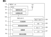
- the BLE module 12 includes an antenna 121, an RF core 122, and a BLE controller 123, as shown in FIGS.
- Antenna 121 is an antenna element for transmitting and receiving radio waves in the frequency band used for BLE communication, i.e., the 2.4 GHz band.
- the 2.4 GHz band can be understood as a frequency band that includes multiple channels (Ch 0 to 39) used for BLE communication.
- Antenna 121 is electrically connected to RF core 122.
- Channel can also be referred to as frequency.
- the channel used for actual communication in other words, the frequency/channel used) changes over time by frequency hopping or in response to instructions from the BLE controller.
- the RF core 122 is a circuit module that performs signal processing for transmitting and receiving wireless signals.
- the RF core 122 may include a modulation circuit, a demodulation circuit, a frequency conversion circuit, an amplifier circuit, a local oscillator, and the like.
- the RF core 122 also has input/output terminals for outputting signals to the antenna 121 and receiving signals from the antenna 121.
- the RF core 122 is connected to the BLE controller so that it can communicate with each other.
- the RF core 122 demodulates the signal received by the antenna 121 and provides it to the BLE controller 123.
- the RF core 122 also modulates transmission data input from the BLE controller 123 and radiates it as radio waves from the antenna 121.
- the RF core 122 may be realized as an IC chip (i.e., a transmission/reception IC).
- the BLE controller 123 corresponds to a communication controller.
- the RF core 122 is configured to be able to transmit and receive modulated signals for data communication as well as CW signals for each channel as a function for CS ranging.
- the RF core 122 also includes an intensity detection unit E1 and a phase detection unit E2.
- the intensity detection unit E1 is a functional unit that measures the reception strength of a received signal.
- the intensity detection unit E1 outputs data indicating the detected reception strength to the BLE controller 123.
- the phase detection unit E2 is a circuit that detects the reception phase, which is the phase angle of the reception signal relative to the output signal of the local oscillator, when a CW signal is received.
- the phase angle of the reception signal relative to the output signal of the local oscillator corresponds to the reception phase.
- the reception phase can be interpreted as the output value of the arctangent whose input value is the ratio of the Q (Quadrature-Phase) component to the I (In-Phase) component of the reception signal.
- the magnitude of the I component corresponds to the strength of the in-phase component of the reception signal.
- the magnitude of the Q component corresponds to the strength of the quadrature component of the reception signal.
- the I component is obtained by multiplying the reception signal by the carrier wave output by the local oscillator.
- the Q component is obtained by multiplying the reception signal by a phase-shifted signal that shifts the phase of the output signal of the local oscillator by 90°.
- the phase-shifted signal can be obtained by passing the output signal of the local oscillator through a phase shift circuit, which is a circuit that shifts the phase by 90°.
- the local oscillator is a circuit that generates a sine wave or cosine wave of the carrier frequency.
- the local oscillator may be realized using a voltage-controlled oscillator (VCO) or the like.
- VCO voltage-controlled oscillator
- the reception phase may be determined based on an IQ signal whose frequency has been reduced to the baseband. The detected reception phase information is used to calculate the device distance.
- the RF core 122 provides the BLE controller 123 with the detection value of the reception phase of the CW signal in association with information indicating the frequency in use (e.g., channel number). Each time the frequency in use is switched, the RF core 122 detects the transmission and reception phase of the CW signal as part of the ranging process. In other words, the BLE controller 123 is provided with data indicating the reception phase for each frequency.
- the BLE controller 123 is a microcomputer that controls the RF core 122.
- the BLE controller 123 includes a processor 124, memory 125, storage 126, and an input/output circuit 127.
- "I/O" in FIG. 4 represents a circuit for input/output, that is, an input/output circuit.
- the BLE controller 123 is responsible for controlling the exchange of data with the DK-ECU 1. Specifically, the BLE controller 123 provides the DK-ECU 1 with received data input from the RF core 122 either sequentially or based on a request from the DK-ECU 1. The BLE controller 123 also outputs transmission data input from the DK-ECU 1 to the RF core 122.
- the BLE controller 123 includes a CS ranging unit F1, a reception strength acquisition unit F2, a startup unit F3, and a report processing unit F4.
- the CS ranging unit F1, the reception strength acquisition unit F2, the startup unit F3, and the report processing unit F4 may each be a software module or a hardware module.
- the following descriptions of the CS ranging unit F1, the reception strength acquisition unit F2, the startup unit F3, and the report processing unit F4 can be replaced with the BLE module 12 or the BLE controller 123 as appropriate.
- the CS ranging unit F1 is a functional unit that executes CS ranging.
- CS ranging here refers to a process of generating distance data indicating the device distance based on a distance-related value, which is a parameter indicating the length of the propagation path of the wireless signal to the mobile device 9.
- CS ranging includes a process of performing bidirectional or unidirectional communication with the mobile device 9 to obtain the distance-related value.
- CS ranging can also be called High Accuracy Distance Measurement (HADM) or phase difference ranging.
- HADM High Accuracy Distance Measurement
- a series of processes including communication for CS ranging may also be referred to as CS ranging processing.
- the CS ranging processing corresponds to the first ranging processing.
- the distance-related value may be a parameter that takes a value according to the propagation time of the wireless signal, in other words, the flight time.
- the reception phase of the signal transmitted from the portable device 9 corresponds to the distance-related value.
- the distance-related value may be the arrival time of the wireless signal transmitted by the portable device 9. Alternatively, the arrival time of the wireless signal may be the RTT.
- These distance-related values are parameters different from the reception strength.
- the CS ranging unit F1 acquires the reception phase for each frequency as a CS ranging process, and calculates the device distance based on the reception phase.
- the reception phase is the phase difference between the CW signal transmitted by the portable device 9 and the CW signal received by the BLE module 12.
- the reception phase can be called the transmission/reception phase difference, the single frequency phase difference, or the first-order phase difference.
- the CS ranging unit F1 acquires the reception phase for each frequency using a one-way method.
- the one-way method is a method in which the reception phase of the CW signal transmitted from the portable device 9 is used as the basis for calculating the phase difference between frequencies, assuming that the initial phase of the CW signal for each frequency transmitted from the portable device 9 is constant.
- the reception phase (in other words, the single frequency phase difference) used as the basis for calculating the phase difference between frequencies can also be acquired using other methods such as a passive two-way method or an active two-way method.
- the passive two-way method and the active two-way method will be described later as a supplementary explanation.
- FIG. 5 is a flowchart showing an example of CS ranging processing, and includes steps S101 to S111.
- the CS ranging processing includes a preparation phase for adjusting the conditions for implementing ranging, a collection phase for collecting reception phases by actually transmitting and receiving CW signals, and a calculation phase for calculating distance based on the collected reception phases for each frequency.
- wireless communication for acquiring distance-related values, such as transmitting and receiving CW signals is also referred to as ranging communication.
- Step S101 is a step in which the BLE module 12 transmits a CS ranging start request to the mobile device 9.
- the CS ranging start request is a BLE signal requesting to start CS ranging.
- the CS ranging start request can be transmitted using a data channel.
- the mobile device 9 Based on receiving the CS ranging start request, the mobile device 9 returns a positive response signal (so-called Ack) to the BLE module 12 (S102).
- the BLE controller 123 transmits a ranging setting notification signal based on receiving an Ack in response to a CS ranging start request from the mobile device 9 (S103).
- the ranging setting notification signal is a BLE signal indicating the parameters for carrying out communication for CS ranging.
- the parameters for carrying out ranging communication may include some or all of the initial phase setting value, the hopping interval, the channel transition amount, and the initial frequency.
- the initial phase setting value is basically set to 0.
- the hopping interval indicates the time for switching the frequency, in other words, the time for maintaining one frequency.
- the hopping interval may be the same as the connection interval used in data communication.
- the channel transition amount is a parameter indicating the amount of change in the channel when switching the channel.
- the channel transition amount may be the same value as the hop increment during data communication.
- the channel transition amount in CS ranging may be determined by the hop increment.
- the initial frequency is the frequency of the CW signal to be transmitted first in a series of ranging communications.
- the initial frequency can be determined randomly.
- Frequency information may be expressed as a channel number.
- the portable device 9 upon receiving the ranging setting notification signal, returns an Ack to the BLE module 12 (S104).
- the BLE module 12 upon receiving the Ack from the portable device 9, transitions to a state in which it can receive a signal of the initial frequency (S105).
- the state in which it can receive a wireless signal can also be referred to as a receiving state or a scanning state.
- the portable device 9 starts transmitting a CW signal at the initial frequency when a predetermined time has elapsed since returning the Ack (S106).
- the transmission of the CW signal can be stopped when a certain time has elapsed since the start of transmission.
- the CW transmission time which is the time for which the CW signal is continuously transmitted, may be set to be shorter than the hopping interval.
- the portable device 9 may start transmitting a CW signal based on receiving a CW transmission request from the BLE module 12 after receiving the ranging setting notification signal.
- the CW transmission request is a BLE signal that requests the transmission of a CW signal.
- the BLE module 12 When the BLE module 12 receives a CW signal from the portable device 9, it detects the reception phase and stores the reception phase data in the memory 125 together with frequency information (e.g., channel number) (S107). The BLE module 12 and the portable device 9 automatically switch the frequency in use at the hopping interval previously agreed upon in step S103 (S108).
- the frequency after the change can be uniquely determined from the frequency before the change and the previously agreed upon channel transition amount.
- the channel in use after the change can be the channel number obtained by adding the hop increment setting value to the channel number before the change.
- the mobile device 9 When the mobile device 9 switches the channel in use, it transmits a CW signal on the new channel in use (S109).
- the BLE module 12 When the BLE module 12 switches the channel in use, it also transitions to a state in which it can receive a signal on the new channel in use. The BLE module 12 then observes the reception phase at the frequency after the switch (S110).
- the BLE module 12 and the portable device 9 repeat steps S108 to S110 until they have collected the reception phases for all channels (Ch 0 to 36) that can be used for data communication.
- the BLE module 12 and the portable device 9 may end the repetitive process when they have collected a predetermined number of reception phases for each channel.
- the required number here may be the same as the number of data channels, or may be smaller than that.
- a configuration in which the required number is set to 37 corresponds to a configuration in which reception phases for all channels are collected. The greater the number of channels for which reception phases are collected, the higher the ranging accuracy, which will be described later.
- the time and power consumption required for ranging communication may increase.
- the required number may be 3, 4, 5, 8, 10, 16, etc.
- the required number may be set to any value between 2 and 37. Of course, if the number of data channels is 37 or more, the required number may be a value of 37 or more.
- the BLE module 12 transmits a ranging end notification signal to the portable device 9 when it has collected the required number of reception phases for each frequency (S111).
- the ranging end notification signal is a data signal for notifying the end of ranging communication.
- the portable device 9 Upon receiving the ranging end notification signal, the portable device 9 transitions to a normal data communication mode.
- the normal data communication mode corresponds to a state in which specified data such as voice data can be transmitted and received.
- the transmission and reception of the ranging end notification signal is an optional element and may be omitted.
- the portable device 9 may return an Ack to the BLE module 12.
- phase change coefficient is a parameter that indicates the degree to which the reception phase changes in response to a change in frequency.
- the phase change coefficient can also be called the degree of phase change, the amount of phase shift, or the correlation coefficient between phase and frequency.
- the inter-frequency phase difference can be called the two-frequency phase difference or the quadratic phase difference.
- the inter-frequency phase difference corresponds to the amount of phase angle displacement due to a change in the frequency used.
- the CS ranging unit F1 of this embodiment calculates a regression line showing the relationship between frequency and reception phase based on the reception phase for each frequency, and adopts the slope of the regression line as the phase change coefficient. This is because the slope of the regression line indicates the amount of change in reception phase relative to the amount of frequency shift.
- the regression line can also be called an approximation line.
- the CS ranging unit F1 may provisionally calculate a first regression line based on all observed received phase data, and may recalculate a second regression line after excluding values (so-called outliers) whose distance from the provisionally calculated first regression line is equal to or greater than a predetermined value.
- the CS ranging unit F1 may use the slope of the second regression line as the phase change coefficient. In this way, the phase change coefficient used in distance calculation may be determined based on a regression line whose population is data excluding outliers. With this configuration, the accuracy of the inter-frequency phase difference, and therefore the ranging accuracy, may be improved.
- the CS ranging unit F1 may calculate the inter-frequency phase difference ( ⁇ ), the differential frequency ( ⁇ f), and the phase change coefficient for each combination of frequencies for which the reception phase can be observed.
- the CS ranging unit F1 may use the average or median of the phase difference change coefficients for each combination of frequencies as the phase difference change coefficient to be used for distance calculation.
- the parameter "C" in the above formula indicates the propagation speed of radio waves (3 ⁇ 10 ⁇ 8 m/sec).
- the CS ranging unit F1 calculates the device distance based on this relational formula.
- the parameter k constituting formula 1 is a design value and is set to 1.0 or 0.5.
- the value of k can be determined depending on whether the transmission and reception phase difference is calculated as a phase change coefficient for one way or a round trip.
- the CS ranging unit F1 stores the calculated device distance data in memory 125.
- the communication distance calculated by the BLE module 12 in the CS ranging process is referred to as the first distance.
- the first distance can also be referred to as the CS ranging value.
- the CS ranging unit F1 may calculate a tentative value (d) of the device distance using ⁇ f and ⁇ for each frequency combination, and use the average or median value of these as the device distance for the antenna being used.
- the steps executed by the BLE module 12 are executed in cooperation with the CS ranging unit F1 and the RF core 122.
- the BLE module 12 determines and notifies the implementation conditions for CS ranging, but this is not limited to this.
- the portable device 9, instead of the BLE module 12, may determine the specifications for implementing ranging communication and transmit a ranging setting notification signal.
- the entity that executes each step may be interchangeable. The above sequence may be executed by the portable device 9 acting as the entity (in other words, the master).
- the reception strength acquisition unit F2 is configured to acquire data indicating the reception strength of the signal from the mobile device 9 for each frequency from the RF core 122. While the BLE module 12 is connected to and communicating with the mobile device 9, the BLE module 12 periodically transmits and receives a data signal for communication check with the mobile device 9. The reception strength acquisition unit F2 acquires reception strength data when the data signal for communication check is received. Note that communication for communication check can be performed at connection intervals. Communication for communication check may also be performed each time channel hopping is performed. The connection interval corresponds to the first interval.
- the signal used to detect the reception strength is not limited to a data signal for confirming communication. It may be a normal data signal or an advertising signal.
- the reception strength may be understood as the reception strength of the signal transmitted from the mobile device 9, unless otherwise noted.
- Startup unit F3 is a software/hardware module that starts up main controller 11 based on the first distance calculated in the CS ranging process being less than a predetermined value (hereinafter also referred to as the activation distance).
- Startup unit F3 transmits an activation signal to main controller 11 based on the state in which the first distance is less than the activation distance continuing for a predetermined time or a predetermined number of times.
- the activation signal is a signal for starting up main controller 11.
- Starting up here means switching from power saving mode to normal mode. Starting up can also be referred to as recovery, activation, activation, wake-up, etc. Starting up of the main controller 11 may be achieved in cooperation with the power supply circuit 14.
- the startup unit F3 may output a control signal to the power supply circuit 14 for starting up the main controller 11, and the power supply circuit 14 may start up the main controller 11 upon receiving the control signal.
- transitioning from normal mode to power saving mode can also be referred to as sleep, shutdown, etc.
- the power saving mode state can also be called a sleep state.
- the activation distance may be set to any value, such as 2.5 m, 3.0 m, 5.0 m, or 6.0 m.
- the report processing unit F4 transmits to the main controller 11 reception strength data indicating the reception strength acquired by the reception strength acquisition unit F2, and first distance data indicating the first distance calculated by the CS ranging unit F1.
- the transmission of various data may be performed periodically while the main controller 11 is operating in normal mode.
- the report processing unit F4 may transmit various data based on a request from the main controller 11.
- the BLE module 12 periodically performs CS ranging processing while the main controller 11 is in power saving mode and is connected to the mobile device 9 for communication. On the other hand, after the main controller 11 returns to normal mode, the BLE module 12 stops performing the periodic CS ranging processing. Of course, the BLE module 12 may continue the periodic CS ranging processing even after the main controller 11 returns to normal mode.
- the BLE module 12 may be configured to perform the CS ranging processing only when a determination event occurs while the main controller 11 is in normal mode.
- the main controller 11 includes, as functional blocks, a communication control unit G1 and a position determination unit G2 as shown in FIG. 6. Each functional block is enabled in normal mode.
- the communication control unit G1 is a software/hardware module that controls the operation of each of the BLE module 12 and the UWB module 2.
- the communication control unit G1 detects the occurrence of a determination event, in other words, a predetermined user action, it causes the BLE module 12 to perform CS ranging processing.
- the occurrence of a determination event may be detected by the body ECU 3, or may be detected by the main controller 11 based on signals input from various sensors and ECUs.
- the communication system control unit G1 also performs a patrol measurement process, which is a process for causing each of the multiple UWB modules 2 to perform UWB ranging in turn.
- the communication system control unit G1 periodically performs the patrol measurement process while operating in normal mode.
- the communication system control unit G1 may dynamically change the patrol measurement interval, which is the interval at which the patrol measurement process is performed, depending on the device distance value observed within a fixed time period and the state of the vehicle Hv.
- the communication system control unit G1 may perform the patrol measurement process based on the detection of the occurrence of a judgment event.
- the position determination unit G2 determines the device position based on the second distance for each UWB module 2 obtained as a result of the patrol measurement process.
- the device position is the position of the portable device 9 relative to the vehicle Hv.
- the device position can be expressed by multiple areas/zones that are pre-set in the vehicle Hv, such as inside the vehicle, a nearby area, an intermediate area, and a distant area.
- the inside of the vehicle is the inside of the vehicle cabin.
- the inside of the vehicle can include the inside of the trunk.
- the inside of the vehicle may be divided into the inside of the vehicle cabin and the inside of the trunk.
- the vicinity area is an area outside the vehicle where the distance from the vehicle Hv is less than a predetermined vicinity judgment value.
- the vicinity judgment value is a parameter that defines the vicinity area outside the vehicle.
- the vicinity judgment value is set to a value such as 1.0 m, 1.5 m, or 2 m.
- the vicinity area can be interpreted as an area where automatic unlocking/locking of the vehicle Hv can be performed.
- the vicinity area may also be referred to as a passive entry area.
- the far area is an area where the distance from the vehicle Hv is equal to or greater than a predetermined far judgment value.
- the far judgment value is a parameter for judging that the mobile device 9 is not present around the vehicle Hv.
- the far judgment value is set to a value such as 5.0 m, 6.0 m, 10 m, or 12 m.
- the intermediate area is an area intermediate between the far area and the near area.
- the intermediate area may be a so-called welcome area in which a predetermined welcome control, such as turning on the exterior lights, is executed upon entry of the mobile device 9 into the area.
- the intermediate area may be an area in which a predetermined control that is not executed when the mobile device 9 is present far outside the vehicle is executed/started, such as authentication by wireless communication with the mobile device 9, tracking of the device position, and shortening of the position judgment period.
- the intermediate area may also be called a standby area, a surrounding area, or the like.
- the intermediate area may be an area in which a user can use a function to remotely park/exit the vehicle Hv.
- the near area, intermediate area, and distant area described above are subdivisions of the outside area.
- the position determination unit G2 may simply determine whether or not the portable device 9 is present inside the vehicle.
- the position determination unit G2 may also determine not only the distance from the vehicle Hv to the portable device 9, but also the direction in which the device is present.
- the device presence direction is the direction in which the portable device 9 is present as viewed from the vehicle Hv/interior anchor.
- the device presence direction may be expressed as right, left, rear, front, etc.
- the near area may be divided into a right area, a left area, and a rear area.
- the right area is a range outside the vehicle that is less than the near determination value from the right door handle or the right B-pillar.
- the left area and the rear area may also be defined based on a specific part of the vehicle Hv.
- the intermediate area may also be subdivided into front, back, left, and right, like the near area.
- the position determination unit G2 of this embodiment determines the stay area, which is the area where the portable device 9 is located, as described above.
- the position determination unit G2 may calculate device position coordinates instead of/in addition to determining the stay area.
- the device position coordinates refer to the position coordinates where the portable device 9 is located in a two-dimensional/three-dimensional coordinate system based on a predetermined position of the vehicle Hv.
- the calculation of the device position coordinates can be performed using a method similar to three-point positioning or multi-point positioning in the technical fields of GPS and position estimation.
- the main controller 11 transmits device position data, which is data indicating the result of the device position determination, to a specific ECU, such as the body ECU 3.
- the main controller 11 may generate device position data periodically while in normal mode.
- the main controller 11 may also perform a patrol measurement process in response to the occurrence of a determination event, and generate device position data.
- the activation determination process is a process for determining whether or not an activation condition of the main controller 11 is satisfied.
- the activation condition includes that the first distance is less than the activation distance. Therefore, the activation determination process includes a CS ranging process.
- the activation condition may include that the reception strength from the portable device 9 observed by the BLE module 12 is equal to or greater than a predetermined intensity threshold. In this case, the activation determination process may include a process of measuring the reception strength of an advertising signal or a data signal from the portable device 9.
- the activation condition may include various items related to the communication state with the portable device 9.
- the items related to the communication state include reception strength, device distance, the degree of variation in reception strength within a certain period of time, whether or not communication connection is possible, and an S/N ratio.
- the activation determination process may be appropriately designed to include a process for collecting values/data for each item constituting the activation condition.
- the BLE module 12 If the start-up conditions are met (S12 YES), the BLE module 12 returns to normal mode by sending a start-up signal to the main controller 11 (S13). If the various data related to the communication state with the portable device 9 collected in the start-up determination process do not meet the start-up conditions (S12 NO), the BLE module 12 re-executes the start-up determination process after a predetermined waiting time has elapsed.
- the start-up determination process may be performed every time an advertisement/data signal is received from the portable device 9.
- the start-up determination process may be performed in parallel with processes such as communication connection and data communication.
- the main controller 11 While in the normal mode, the main controller 11 periodically performs a stop determination process as shown in FIG. 8 (S21). Note that the stop determination process may be triggered by a user operation to turn off the driving power source or a door locking operation, etc.
- the stop determination process is a process for determining whether or not the stop conditions of the main controller 11 are satisfied.
- the stop conditions include the vehicle Hv being locked with the driving power source turned off.
- the stop conditions may also include the smallest value of the multiple second distances collected in the patrol measurement process being equal to or greater than a predetermined stopping distance.
- the stopping distance may be set to 10 m, 15 m, or the like.
- the stop conditions may also include a state in which the reception strength is less than a predetermined stopping strength for a predetermined period of time.
- the stop conditions may also include various items related to the communication state with the portable device 9.
- the stop determination process may be appropriately designed to include a sequence for collecting values/data for each item constituting the start conditions.
- the main controller 11 performs a predetermined stop preparation process and then transitions to power saving mode (S23).
- the stop preparation process may include saving the current vehicle state in the storage 113 and notifying the BLE module 12 that the mode will soon transition to power saving mode. If the various data related to the communication state with the portable device 9 collected in the stop determination process does not meet the stop condition (S22 NO), the main controller 11 performs the stop determination process after a predetermined waiting time has elapsed.
- FIG. 9 is a flowchart showing a more specific example of the operation of the DK-ECU 1 in a scene where a user approaches a parked vehicle Hv.
- the flowchart in FIG. 9 shows the flow from when the main controller 11 returns from the power saving mode to the normal mode until the position determination process is performed.
- the series of processes related to the startup of the main controller 11 and the position determination are referred to as the user approach response process.
- the user approach response process may include steps S201 to S210.
- step S201 is performed, the main controller 11 is in the power saving mode.
- the portable device 9 is sufficiently far away from the vehicle Hv, and the portable device 9 and the BLE module 12 are not connected.
- Step S201 is a step in which the BLE controller 123 determines whether or not a communication connection with the portable device 9 has been established. If a communication connection with the portable device 9 has been established (S201 YES), the BLE controller 123 starts periodic execution of CS ranging (S202). Periodic execution of CS ranging can be continued until the communication connection with the portable device 9 is disconnected or the main controller 11 is started.
- Step S203 is a step for determining whether or not the device distance obtained by CS ranging (i.e., the first distance) is less than the activation distance. Step S203 is performed each time CS ranging is performed. "D1" in FIG. 9 indicates the first distance. “ThD1" indicates the activation distance. The first distance used for comparison with the activation distance, in other words, for determining whether or not to activate the main controller 11, may be the most recently calculated value.
- Steps S201 to S203 correspond to the activation determination process described above.
- the first distance used to determine whether to start the main controller 11 may be the average or median of the first distances observed within a fixed time period, that is, the moving average/moving median.
- a configuration in which the main controller 11 is started based on the moving average/median of the first distances being equal to or greater than the start-up threshold can further reduce the risk of starting the main controller 11 unnecessarily.
- the main controller 11 transitions each UWB module 2 to a state in which communication is possible (S206). Then, the main controller 11 starts periodic execution of the patrol measurement process (S207). The periodic execution of the patrol measurement process may continue until the driving power source of the vehicle Hv is turned on or the communication connection with the portable device 9 is terminated.
- the main controller 11 may transmit a UWB ranging start request to the portable device 9 via BLE.
- This enables the portable device 9 to activate the UWB module 94 and respond to a UWB signal from the vehicle Hv.
- the transmission of the UWB ranging start request is an optional element and may be omitted. In a configuration in which the portable device 9 always activates the UWB module 94, the transmission of the UWB ranging start request can be omitted.
- the contents of the preparatory processes for various ranging processes can be changed to suit the configuration of the portable device 9.
- Step S208 is a step in which the main controller 11 collects second distance data from each of the multiple UWB modules 2 as a result of the cyclic measurement process. When the collection of the second distance data is completed, the main controller 11 executes step S209.
- Step S209 is a step in which the main controller 11 determines the device location based on the second distance observed by multiple UWB modules 2.
- the device location may be determined using various algorithms. For example, the main controller 11 determines that the device location is inside the vehicle if the second distance observed by the in-vehicle anchor 2A is less than a predetermined interior determination value.
- the interior determination value may be set to 1 m, for example.
- the device location may be determined to be outside the vehicle if the second distance observed by the in-vehicle anchor 2A is equal to or greater than a predetermined value.
- the main controller 11 may determine that the device location is a nearby area. If there is no outdoor unit with a second distance less than the proximity determination value and there is an outdoor unit observing a second distance less than the far determination value, the main controller 11 may determine that the device location is a far area if there is no outdoor unit observing a second distance less than the far determination value. If the UWB module 2 observing the smallest second distance is the left anchor 2C, the main controller 11 may determine that the portable device 9 is on the left side of the vehicle.
- the main controller 11 may calculate the device position coordinates by combining the second distances of multiple UWB modules 2.
- the main controller 11 may determine the device position by combining the position-related data reported from each UWB module 2.
- the main controller 11 may also determine the device position using the reception strength of the signal from the portable device 9 observed by the BLE module 12 and the UWB module 2. If the reception strength at the interior anchor 2A is greater than the maximum reception strength observed at the outdoor unit by a predetermined value or more, and the second distance observed at the interior anchor 2A is within a predetermined value (e.g., 2 m), the main controller 11 may determine that the device position is inside the vehicle.
- the main controller 11 When the main controller 11 has completed determining the device position, it transmits device position data indicating the result of the determination to the body ECU 3. Based on the device position data provided by the DK-ECU 1, the body ECU 3 can execute predetermined controls such as unlocking/locking the vehicle Hv and turning on the power.
- FIG. 10 is a flowchart for explaining the operation of the DK-ECU1 in this control pattern, and shows the sequence following step S204 in Figure 9.
- Step S301 shown in Figure 10 is a process after the main controller 11 is started, in which the main controller 11 starts up each UWB module 2.
- Step S302 is a step in which the main controller 11 starts performing periodic measurement processing.
- Step S303 is a step in which the BLE module 12 performs CS ranging at a timing when UWB ranging is not being performed by the UWB module 2.
- the BLE module 12 can obtain the timing when UWB ranging is not being performed by the UWB module 2 from the main controller 11.
- the BLE module 12 may be configured to perform CS ranging processing based on an instruction from the main controller 11.
- Step S303 can be performed at a predetermined interval.
- Step S304 is a step in which the main controller 11 acquires the second distance from the multiple UWB modules 2 and acquires the first distance from the BLE module 12.
- Step S305 is a step in which the main controller 11, acting as the position determination unit G2, determines the device position based on the first distance data and the multiple second distance data.
- Step S306 is a step in which the main controller 11 transmits the determination result of the device position to the body ECU 3, similar to step S210.
- the first distance in addition to the second distance to determine the device position, it is expected that the accuracy of the position determination can be improved.
- the main controller 11 may be configured to classify the multiple UWB modules 2 into unnecessary anchors and useful anchors based on the previous device position determination result, and not use the unnecessary anchors in the cyclic measurement process.
- the unnecessary anchors are UWB modules 2 that do not perform UWB ranging process in the cyclic measurement process, in other words, UWB modules 2 that are not operated.
- the unnecessary anchors can be called invalid anchors.
- the useful anchors are UWB modules 2 that perform UWB ranging process in the cyclic measurement process.
- the UWB modules 2 other than the unnecessary anchors correspond to useful anchors.
- the useful anchors can be called valid anchors.
- FIG. 11 is a flowchart showing an example of the operation of the main controller 11 corresponding to this technical concept, and includes steps S401 to S403.
- the flowchart shown in FIG. 11 can be executed in response to the completion of the device position determination process in the previous patrol measurement process, etc.
- Step S401 is a step in which the main controller 11 refers to the previous device position determination result.
- Step S402 is a step in which the main controller 11 classifies each UWB module 2 into an unnecessary anchor or a useful anchor based on the device position information read in step S401.
- the main controller 11 determines that the portable device 9 is present in the left area of the vehicle Hv as shown in FIG. 12, it sets the right anchor 2B as an unnecessary anchor. Also, when the main controller 11 determines that the portable device 9 is present on the right side of the vehicle Hv, it sets the left anchor 2C as an unnecessary anchor. In this way, the main controller 11 may set the outer anchor located on the opposite side to the direction in which the device is present as an unnecessary anchor.
- the main controller 11 may set the interior anchor 2A as an in-vehicle anchor as an unnecessary anchor until the door/window is opened. Also, if the main controller 11 determines that the portable device 9 is inside the vehicle, it may set the right anchor 2B, the left anchor 2C, and the rear anchor 2D as outer anchors as unnecessary anchors until the door/window is opened.
- Data indicating the correspondence between the device position/device direction and the unnecessary anchors may be stored in advance in the storage 113 in the form of a data table or program.
- the main controller 11 can dynamically change the settings of the unnecessary anchors according to the device position/device direction based on the preregistered data/program.
- the main controller 11 can be considered as a computer that stops the UWB module 2 that is installed in an unwanted zone that is determined according to the device position.
- the unwanted zone corresponds to the exterior of the vehicle on the opposite side to the direction in which the device is present.
- the exterior of the vehicle can correspond to the unwanted zone.
- the interior of the vehicle can correspond to the unwanted zone.
- the main controller 11 stops the operation of that UWB module 2 (S403).
- the setting of the unnecessary anchor may be updated for each circular search process. Also, the setting of the unnecessary anchor may be reset every time the circular search process is performed a predetermined number of times (e.g., three times). A configuration in which the setting of the unnecessary anchor is reset every predetermined number of times can reduce the risk of erroneously determining the device position by continuing to disable some UWB modules 2.
- the BLE controller 123 may be configured to start performing regular CS ranging when the reception strength becomes equal to or greater than a predetermined value after the BLE controller 123 has established a communication connection with the portable device 9. In other words, the BLE controller 123 may be configured to perform the CS ranging process on the condition that the BLE controller 123 has established a communication connection with the portable device 9 and the reception strength is equal to or greater than a predetermined value.
- FIG. 13 is a flowchart showing an example of control corresponding to this technical idea, and includes steps S501 to S506.
- the flowchart shown in FIG. 13 can be implemented as an alternative process to steps S201 to S204 in FIG. 9.
- step S501 can be executed periodically while the main controller 11 is in the power saving mode.
- step S501 shown in FIG. 13 is a step in which the BLE controller 123 determines whether or not a communication connection has been established with the mobile device 9. If a communication connection has been established (S501 YES), periodic data communication with the mobile device 9 and measurement of the reception strength are started (S502). Periodic data communication with the mobile device 9 can be continued while the communication connection is maintained. Note that if the communication connection with the mobile device 9 is terminated, the process is repeated from step S501.
- the periodic communication may be the transmission and reception of an advertising signal.
- Step S503 is a step for determining whether the reception strength of a data signal transmitted from the mobile device 9 as periodic data communication is equal to a predetermined intensity threshold. Step S503 is performed each time periodic communication is performed.
- “RSSI” in FIG. 13 indicates the observed value of the reception strength of the signal from the mobile device 9.
- “ThRSSI” indicates the intensity threshold.
- the intensity threshold is set to a value corresponding to the reception strength observed in a situation where the device distance is a predetermined value (e.g., 10 m).
- the ideal environment means a situation where no obstacles exist between the mobile device 9 and the BLE module 12.
- the intensity threshold can be set by testing or simulation.
- the reception strength used for the comparison with the strength threshold in step S503, in other words, for determining whether or not to perform CS ranging, may be the most recently observed value. Also, the reception strength used for determining whether or not to perform CS ranging may be the average or median of the reception strength observed within a fixed period of time, that is, the moving average/moving median. This configuration can reduce the risk of performing CS ranging processing unnecessarily.
- Step S505 is a step for determining whether or not the latest first distance obtained by the CS ranging process is less than the activation distance. The determination in step S505 is performed each time the CS ranging process is executed.
- the BLE controller 123 activates the main controller 11 (S506).
- the subsequent processing may be similar to steps S205 to S210 in FIG. 9 or steps S301 to S306 in FIG. 10. Steps S501 to S505 also correspond to an example of the activation determination processing described above.
- the above configuration can reduce the risk of performing CS ranging processing in situations where the reception strength is low, that is, in scenes where there is a high possibility that the distance between the portable device 9 and the vehicle Hv is still far. Naturally, reducing the frequency with which the CS ranging processing is performed leads to a reduction in power consumption.
- the above configuration can further reduce power consumption. Note that the intensity threshold can also be considered as a parameter for starting CS ranging in one aspect.
- the BLE controller 123 may be configured to perform CS ranging processing under the condition that it is already connected for communication with the mobile device 9 and the variation in reception strength is less than a predetermined value.
- ⁇ indicates the degree of variation in reception strength.
- Th ⁇ represents a threshold value for the degree of variation in reception strength.
- the degree of variation in reception strength can be expressed by variance in statistics. Of course, the degree of variation in reception strength may also be expressed by standard deviation or the difference between the maximum value and the minimum value.
- Step S603 is a step for determining whether the degree of variation in reception strength observed within a fixed period of time is less than a predetermined threshold. If the degree of variation in reception strength is less than the predetermined threshold (S603 YES), the BLE controller 123 starts regular execution of CS ranging processing. In other words, the BLE controller 123 may be configured not to start regular execution of CS ranging processing if the degree of variation in reception strength is equal to or greater than the threshold.
- the degree of variation in reception strength is greater than when there is no wall.
- a large degree of variation in the reception signal suggests that the portable device 9 may be present inside a building such as a house or office.
- the vehicle Hv is unlikely to be used by the user. Therefore, there is little need to perform the CS ranging process itself. According to the configuration in which the control flow shown in FIG. 14 is applied, the risk of performing the CS ranging process can be reduced in a scene in which the portable device 9 is present inside a building.
- Standby corresponds to a state in which the vehicle Hv is parked.
- the risk of the main controller 11 and the UWB module 2 being unnecessarily activated can also be reduced.
- the BLE controller 123 may be configured to perform CS ranging processing under the conditions that it is already connected for communication with the mobile device 9, the reception strength is equal to or greater than a predetermined value, and the variation in reception strength is less than a predetermined value. This configuration can further reduce system malfunctions and power consumption.
- the BLE module 12 may successively detect the reception strength of a BLE signal, such as an advertisement signal, periodically transmitted from the portable device 9, and execute CS ranging processing based on the reception strength being equal to or greater than an intensity threshold.
- Steps S701 to S704 shown in FIG. 15 correspond to the above-mentioned steps S503 to S506.
- the flowchart shown in FIG. 15 may be started based on the main controller 11 switching from the normal mode to the power-saving mode. Note that step S701 is executed at a predetermined interval while the main controller 11 is in the power-saving mode.
- the first interval may be the advertisement interval.
- the interaction between the portable device 9 and the in-vehicle system VS for each state of the in-vehicle system VS will be described.
- the BLE module 12 starts the CS ranging process on the condition that the reception strength is equal to or greater than a predetermined value
- the in-vehicle system VS can take a first waiting state, a second waiting state, a third waiting state, and a position determination state as a status according to the device position.
- the first waiting state is a state in which there is no communication connection with the portable device 9.
- the first waiting state corresponds to a situation in which the portable device 9 is outside the communication range of the BLE module 12, in other words, a situation in which the portable device 9 is sufficiently far away from the vehicle Hv.
- the first waiting state can be referred to as a connection waiting state.
- the mobile device 9 transmits an advertising signal at an interval that is a predetermined advertising interval plus a random time (so-called advertising delay). Also, the BLE module 12 enters a reception standby state at a predetermined scan interval and searches for a signal from the mobile device 9.
- the size of the scan window which corresponds to the length of time for which the reception standby state is maintained, may be designed as appropriate.
- the lengths of the scan interval and advertising interval can also be set to various values.
- the various interval values are preferably set to values that allow for a quick connection when the user approaches the vehicle Hv.
- the advertising interval can be set to a value between 20 milliseconds and 400 milliseconds, such as 37.5 milliseconds, 50 milliseconds, 80 milliseconds, 100 milliseconds, etc.
- the advertising interval may be set to a value greater than 400 milliseconds as long as it complies with the BLE standard.
- the advertising interval may also be set to a value shorter than the scan interval.
- the second waiting state is a state in which the portable device 9 and the BLE module 12 are connected for communication and the reception strength is less than the strength threshold.
- the second waiting state can be called a strength determination state.
- the BLE module 12 does not perform CS ranging communication.
- the portable device 9 and the BLE module 12 periodically perform data communication at a predetermined connection interval.
- the communication content may be various, such as a communication confirmation.
- the connection interval may be set to a value between 7.5 milliseconds and 200 milliseconds, such as 30 milliseconds or 40 milliseconds.
- the connection interval may also be set to a value exceeding 200 milliseconds within a range that complies with the BLE standard.
- the third waiting state corresponds to a state in which the portable device 9 and the BLE module 12 are connected for communication, the reception strength is less than the strength threshold, and the device distance is equal to or greater than the activation distance.
- the portable device 9 and the BLE module 12 periodically perform data communication at a predetermined connection interval, and also periodically perform communication for CS ranging.
- the third waiting state can be referred to as a distance determination state.
- the CS ranging interval which is the interval at which the BLE module 12 executes CS ranging communication, may be set to two or three times the connection interval. It is preferable that the CS ranging interval is set longer than the connection interval as shown in FIG. 18. By making the CS ranging interval longer than the execution interval of periodic data communication, it is expected that the effect of further suppressing power consumption can be achieved.
- the CS ranging interval corresponds to the second interval. Note that "CS-Ranging Interval" in FIG. 18 indicates the CS ranging interval.
- CW signals can be transmitted and received at multiple frequencies.
- One CS ranging communication may be the transmission and reception of a CW signal at one frequency.
- the duration of one CS ranging communication can be adjusted by the length of the CW signal (tone).
- the main controller 11 and the UWB module 2 maintain a sleep state. Note that, as explained with reference to FIG. 9, in a configuration in which reception strength information is not used to determine whether the main controller 11 or the like is started, the second waiting state is omitted, and a transition can be made from the first waiting state (connection waiting state) to the third waiting state (distance determination state).
- the position determination state is a state in which the main controller 11 periodically performs patrol measurement processing.
- the position determination state corresponds to a state in which the portable device 9 is present within the activation distance of the vehicle Hv (actually the BLE module 12).
- the main controller 11 and the UWB module 2 are activated.
- the in-vehicle system VS periodically performs data communication via BLE and ranging communication via UWB with the portable device 9.
- the position determination state can be rephrased as the system operation state.
- the UWB ranging interval which is the interval at which the main controller 11 causes the UWB module 2 to execute UWB ranging communication, may be set to three or four times the connection interval. It is preferable that the UWB ranging interval is set longer than the connection interval as shown in FIG. 19. By making the UWB ranging interval longer, it is expected that the effect of further suppressing power consumption can be achieved. Note that "UWB-Ranging Interval" in FIG. 19 indicates the UWB ranging interval.
- One UWB ranging communication may include UWB ranging communication in multiple UWB modules 2. In other words, one UWB ranging communication shown in FIG. 19 may be communication equivalent to a cyclic measurement process.
- the UWB ranging interval can also be referred to as a cyclic measurement interval.
- the UWB ranging interval may be set to a value between 150 milliseconds and 400 milliseconds, such as 180 milliseconds or 280 milliseconds.
- the UWB ranging interval may be longer than the CS ranging interval. Additionally, the UWB ranging interval may be the same as or shorter than the CS ranging interval.
- the 2.4 GHz band signal used in BLE is easily affected by reflectors and human bodies. Therefore, even if the distance is constant, the reception strength is likely to vary depending on how the user holds the portable device 9 and the surrounding environment.
- the developers of the present disclosure have considered a comparative configuration in which the first distance is not used and the main controller 11 and the like are activated when the reception strength reaches a predetermined value or greater.
- the threshold value for the reception strength in the comparative configuration is set to a value corresponding to the reception strength observed in a situation in which the device distance in an ideal environment is 5.5 m.
- the description of the main controller 11 and the like refers to the main controller 11 and the UWB module 2.
- whether or not to start the main controller 11 is determined based on the first distance determined based on the propagation time of the signal from the portable device 9, rather than on the reception strength.
- the first distance determined according to the propagation time of the signal has a smaller distance measurement error due to the communication environment than the reception strength. In other words, the variation in the distance measurement from the vehicle Hv to the portable device 9 is reduced.
- the configuration of the present embodiment it is possible to reduce the variation in the area in which the main controller 11 and the like are started, and therefore the system operation can be stabilized. Furthermore, it is possible to reduce the risk of confusing the user due to a malfunction or delay in the system operation.
- the UWB module 2 also starts up after the main controller 11 starts up. In other words, the UWB module 2 also stops operating while the main controller 11 is in the power saving mode.
- the UWB module 2 can also maintain a stopped state until the first distance becomes less than the activation distance. Therefore, the activation frequency of the UWB module 2 can be reduced, and power consumption can be further reduced.
- the above configuration can also be interpreted as a configuration in which the UWB module 2 is transitioned to a communication-enabled state based on the first distance observed by the BLE module 12 becoming less than a predetermined value.
- the BLE module 12 may transmit an activation signal to the UWB module 2 based on the CS ranging result being less than the activation distance.
- the activation order of the main controller 11 and the UWB module 2 may be reversed.
- the BLE module 12 may activate some or all of the UWB modules 2 based on the CS ranging result being less than the activation distance.
- the UWB module 2 or the BLE module 12 may activate the main controller 11 based on the ranging result of at least one UWB module 2 being less than a predetermined value.
- the main controller 11 may cooperate with the body ECU 3 to execute welcome control such as turning on welcome lights and operating the air conditioner.
- This configuration corresponds to a system in which the main controller 11 executes welcome control when the first distance measured by the BLE module 12 through CS ranging becomes less than the startup distance.
- the first distance determined by CS ranging represents the device distance more accurately than the reception strength. Therefore, a configuration in which welcome control is executed when the first distance becomes less than a predetermined value can reduce the risk of unnecessarily executing well control compared to a configuration in which welcome control is executed when the reception strength becomes equal to or greater than a predetermined value.
- a variety of devices, such as the main controller 11 and a UWB module can be the target device.
- the target device may be the body ECU 3, etc.
- the BLE module 12 is disposed inside the housing of the DK-ECU 1, but the present invention is not limited to this. As shown in Fig. 20, the BLE module 12 may be disposed outside the housing of the DK-ECU 1. The BLE module 12 disposed outside the housing operates to activate the DK-ECU 1 when the CS distance measurement result falls below the activation distance.
- the body ECU 3 and the like are omitted from Fig. 20.
- the in-vehicle system VS may include a distance measurement module 12 ⁇ as a BLE module in addition to the gateway module 12 ⁇ .
- the gateway module 12 ⁇ is a BLE module that communicates with the portable device 9 even while the main controller 11 is in a power saving mode and wakes up the main controller 11 based on the CS distance measurement result.
- the gateway module 12 ⁇ is a configuration equivalent to the BLE module 12 described above.
- BLE-GW in FIG. 21 indicates a module that functions as the gateway module 12 ⁇ among the in-vehicle modules that perform BLE communication.
- GW is an abbreviation for gateway.
- the expression “gateway module” can be replaced with "representative module” or "BLE-GW module”.
- the body ECU 3 and the like are omitted from the illustration.
- the ranging module 12 ⁇ is a BLE module that functions as an anchor.
- the ranging module 12 ⁇ performs CS ranging processing based on instructions from the main controller 11.
- "BLE-CS" in FIG. 21 indicates that the in-vehicle BLE module is a module for CS ranging.
- the expression "ranging module” can be replaced with "BLE-CS module", "BLE anchor”, "CS anchor”, etc.
- the ranging module 12 ⁇ may be a BLE module dedicated to ranging.
- the ranging module 12 ⁇ may be a BLE module used only for ranging and reception strength measurement.
- the ranging module 12 ⁇ may temporarily perform data communication with the mobile device 9 while having a primary role of ranging.
- the ranging module 12 ⁇ stops operating while the main controller 11 is in the power saving mode.
- the ranging module 12 ⁇ may be configured to be activated intermittently and perform CS ranging processing even while the main controller 11 is in the power saving mode.
- the ranging module 12 ⁇ may be activated when the gateway module 12 ⁇ performs CS ranging processing, and may eavesdrop (sniff) on the CW signal transmitted from the mobile device 9 and detect the receiving phase for each frequency.
- Sniffing is a technique in which a BLE module other than the gateway module 12 ⁇ uses channel information provided by the gateway module 12 ⁇ to eavesdrop on communication between the mobile device 9 and the gateway module 12 ⁇ .
- the channel information is information indicating the channel used for data communication between the gateway module 12 ⁇ and the mobile device 9 (hereinafter, channel information).
- the channel information may be a specific channel number, or a parameter indicating a transition rule of the channel in use (so-called hop increment). It is preferable that the channel information includes the currently used channel number and the hop increment.
- the channel information may be deployed to each ranging module 12 ⁇ via the main controller 11.
- the channel information may also be deployed to each ranging module 12 ⁇ directly from the gateway module 12 ⁇ , in other words, without going through the main controller 11.
- the BLE module other than the gateway module 12 ⁇ is the ranging module 12 ⁇ .
- ranging module 12 ⁇ In BLE, frequency hopping is performed after communication connection, so normally only the gateway module 12 ⁇ that is connected to communication can capture the data signal from the mobile device 9.
- sniffer technology channel information is deployed to each ranging module 12 ⁇ , so that ranging module 12 ⁇ can also capture the data signal from the mobile device 9.
- ranging module 12 ⁇ can recognize which of the many channels available in BLE can be used to receive a signal from the mobile device 9.
- ranging module 12 ⁇ can detect the reception strength, reception phase, reception time, etc. of the signal from the mobile device 9 even without communication connection. Therefore, a configuration that applies sniffer technology has the advantage that multiple BLE modules can perform CS ranging processing in parallel.
- FIG. 21 illustrates an example in which an internal module functions as the gateway module 12 ⁇ , but this is not limiting. As mentioned above, the gateway module 12 ⁇ may be an external module.
- FIG. 21 shows a configuration in which multiple external modules as distance measurement modules 12 ⁇ are connected to the DK-ECU 1.
- the multiple distance measurement modules 12 ⁇ can be distributed over the right side, left side, rear end, and part or all of the front end of the vehicle Hv.
- the BLE module can be located on the side of the vehicle in the B-pillar, C-pillar, side mirror, door handle, side sill, roof edge, etc.
- the BLE module can be located inside the rear bumper, near the license plate, the top/bottom of the rear glass, trunk door handle, etc.
- the BLE module can be located at the front end of the vehicle in the front bumper, front grille, top/bottom of the windshield, etc.
- the in-vehicle system VS may be equipped with only one distance measurement module 12 ⁇ .
- the position determination unit G2 may determine the device position using the CS ranging results from the multiple ranging modules 12 ⁇ . In other words, the multiple UWB modules 2 may be omitted.
- the second communication unit may be the ranging module 12 ⁇ .
- the position determination unit G2 may determine the device position using the CS ranging results from the multiple ranging modules 12 ⁇ and the UWB ranging results from the multiple UWB modules.
- the position determination unit G2 may use the CS ranging results from multiple ranging modules 12 ⁇ to determine the approximate device position or device presence direction, and set unnecessary anchors based on the results. This configuration makes it possible to reduce the number of UWB modules 2 that operate after the main controller 11 is started.
- the BLE module 12 may obtain single-frequency phase differences for each frequency by an active two-way system or a passive two-way system, and use the single-frequency phase differences to calculate the inter-frequency phase difference.
- an active two-way system or a passive two-way system
- the single-frequency phase differences to calculate the inter-frequency phase difference.
- the active two-way method is a method in which an initiator and a reflector transmit and receive CW signals to each other, each detects the phase difference between the transmitted signal and the received signal, and uses these two phase differences to determine the single-frequency phase difference.
- the active two-way method includes a process in which the initiator and reflector transmit and receive CW signals to each other, and a process in which the reflector transmits the observed received phase ( ⁇ r) to the initiator.
- the initiator is the device that starts communication, in other words, the device that requests a response.
- the reflector is the device that returns the response.
- the BLE module 12 corresponds to the initiator, and the mobile device 9 corresponds to the reflector.
- the average value of ⁇ i and ⁇ r is the single frequency phase difference ( ⁇ ) in which the initial phase components of the initiator and reflector are offset.
- the active two-way method corresponds to a method that calculates the average value of the reception phase at the initiator and the reception phase at the reflector as the single frequency phase difference.
- the average value of ⁇ i and ⁇ r is taken as the single frequency phase difference.
- the single frequency phase difference can be calculated as ⁇ i + ⁇ r.
- the passive two-way system is also a system in which an initiator and a reflector transmit and receive CW signals to each other.
- the difference from the active two-way system is that the reflector reflects the receiving phase of the CW signal transmitted from the initiator in the initial phase of the transmitted signal and transmits it.
- A represents the amplitude.
- n is a natural number and corresponds to the interval from when the reflector receives the CW signal to when it transmits the CW signal.
- the receiving phase observed by the initiator does not include the initial phase component of the reflector.
- the receiving phase observed by the initiator is the same value as when the CW signal is received after being reflected by a reflecting object such as a wall and returned.
- the initiator can calculate the single-frequency phase difference without obtaining the reception phase from the reflector.
- the passive two-way method has the advantage over the active two-way method that the reflector does not need to send a reception phase message.
- the single-frequency phase difference and therefore the inter-frequency phase difference can be calculated in a variety of ways.
- the BLE controller 123 may calculate the first distance using the RTT instead of/in addition to the inter-frequency phase difference.
- the RTT measured by the BLE controller 123 is the time from transmitting a predetermined BLE signal requesting a response to receiving a response signal from the mobile device 9.
- the RTT also corresponds to a distance-related value.
- Transmitting and receiving a signal for measuring the RTT also corresponds to an example of CS ranging communication. Calculating the phase change coefficient or the RTT substantially corresponds to calculating the device distance.
- the process of generating data indicating the device distance such as the phase change coefficient or the RTT, based on the phase, flight time, or arrival time of the signal received from the mobile device 9 is also included in the concept of the first ranging process.
- Calculating the distance also includes generating data indirectly indicating the distance.
- the above embodiment is applicable to various vehicles that run on roads. That is, the present disclosure can be installed in various vehicles that can run on roads, such as two-wheeled vehicles, three-wheeled vehicles, etc., in addition to four-wheeled vehicles. Motorized bicycles can also be included in two-wheeled vehicles.
- the in-vehicle system VS may be configured so that multiple in-vehicle BLE modules operate as masters of the mobile device 9 using multipoint technology. Also, multiple in-vehicle BLE modules may be configured so that they operate as slaves of the mobile device 9.
- the communication method between the BLE module 12 and the mobile device 9 is not limited to BLE, and may be Bluetooth Classic or the like.
- Wireless communication compliant with Bluetooth includes both communication compliant with Bluetooth Low Energy and communication compliant with Bluetooth Classic.
- the communication standard used for distance measurement communication after the main controller 11 is started is not limited to BLE or UWB, but may be Wi-Fi (registered trademark), EnOcean (registered trademark), Zigbee (registered trademark), etc.
- the second communication unit may be a communication module that complies with Wi-Fi, etc.
- a position determination device for determining a position of a mobile device relative to a vehicle, comprising: A first communication unit (12) that performs wireless communication with the portable device in accordance with Bluetooth (registered trademark); A computer (11) that performs processing related to determining the location of the mobile device, The computer has a normal mode and a power saving mode as states, the first communication unit is configured to maintain a state in which communication with the portable device is possible even while the computer is in the power saving mode; the first communication unit executes a first distance measurement process to calculate a first distance from the first communication unit to the portable device using data related to a reception phase, a flight time, or an arrival time of a wireless signal transmitted from the portable device; The first communication unit is a position determination device that compares the first distance obtained as a result of the first ranging process with a predetermined value, and transitions the computer from the power saving mode to the normal mode based on the comparison result.
- the position determination device is used in connection with a second communication unit (2) that is disposed in the vehicle and is capable of wireless communication with the portable device,
- the computer includes: activating the second communication unit based on a return from the power saving mode to the normal mode; causing the second communication unit to perform a second distance measurement process for calculating a second distance, which is a distance from the second communication unit to the portable device, using data related to a reception phase, a flight time, or an arrival time of a wireless signal transmitted from the portable device; and determining a position of the mobile device based on the second distance determined based on a result of the second ranging process.
- the second communication unit is a communication module that performs ultra-wideband (UWB) communication
- the second distance measurement process includes measuring a flight time of the wireless signal by transmitting and receiving an impulse signal used in UWB communication with the portable device, and calculating the second distance based on the measured flight time, The position determination device described in Technical Concept 2, wherein the second communication unit performs the second distance measurement process based on instructions from the computer.
- the computer includes: causing the first communication unit to continue the first distance measurement process even after the mode is switched to the normal mode; The position determination device according to Technical Idea 2 or 3 determines the position of the mobile device based on the first distance and the second distance.
- a position determination device according to any one of Technical Concepts 2 to 4, which is used in connection with a plurality of the second communication units, The computer includes: acquiring the second distances from each of the second communication units; determining a location of the portable device based on the second distance for each of the second communication units; and stopping operation of some of the second communication units in accordance with the determined location of the portable device.
- the second communication units include a right communication unit (2B) arranged on a right side of the vehicle and a left communication unit (2C) arranged on a left side of the vehicle,
- the computer includes: When the position of the portable device is determined to be on the right side of the vehicle, the operation of the left side communication unit is stopped, The position determination device according to Technical Idea 5, wherein when the position of the portable device is determined to be on the left side of the vehicle, operation of the right side communication unit is stopped.
- the first communication unit is receiving a signal from the portable device periodically at a first interval and acquiring a reception strength of the received signal; A position determination device described in any one of technical ideas 1 to 6, which executes the first ranging process when the observed value of the reception strength is equal to or greater than a predetermined strength threshold.
- the first communication unit compares the observed value of the reception strength with a predetermined threshold, and periodically executes the first distance measurement process at a second interval based on a result of the comparison, The position determination device according to Technical Concept 7, wherein the second interval is set longer than the first interval.
- the first communication unit is When the computer is in the power saving mode and has not established a communication connection with the portable device, intermittently transmitting or scanning a signal to establish a communication connection with the portable device;
- the position determination device according to Technical Idea 7 or 8, which starts receiving or transmitting periodic data signals based on the establishment of a communication connection with the mobile device.
- the first communication unit is storing the observed value of the reception strength in a memory;
- the apparatus, system, and methods thereof described in the present disclosure may be realized by a dedicated computer comprising a processor programmed to execute one or more functions embodied in a computer program.
- the apparatus and methods described in the present disclosure may be realized by a dedicated hardware logic circuit.
- the apparatus and methods described in the present disclosure may be realized by one or more dedicated computers configured by a combination of a processor that executes a computer program and one or more hardware logic circuits.
- Some or all of the functions provided by the BLE controller 123 may be realized as hardware. Aspects of realizing a certain function as hardware include a mode of realizing the function using one or more ICs, etc.
- the processor computation core
- the processor may be a CPU, an MPU, a GPU, a DFP (Data Flow Processor), etc.
- the BLE controller 123 may be realized by any of a system-on-chip (SoC), an IC (Integrated Circuit), and an FPGA (Field-Programmable Gate Array).
- SoC system-on-chip
- IC Integrated Circuit
- FPGA Field-Programmable Gate Array
- the concept of IC also includes ASICs (Application Specific Integrated Circuits).
- a computer program may be stored in a computer-readable non-transitory tangible storage medium as instructions executed by a computer.
- the program recording medium may be a hard-disk drive (HDD), a solid-state drive (SSD), flash memory, etc.
- HDD hard-disk drive
- SSD solid-state drive
- flash memory etc.
- This disclosure also includes within its scope a program for causing a computer to function as a BLE controller 123 or main controller 11, and a non-transitory tangible recording medium such as a semiconductor memory on which this program is recorded.
Landscapes
- Engineering & Computer Science (AREA)
- Radar, Positioning & Navigation (AREA)
- Remote Sensing (AREA)
- Computer Networks & Wireless Communication (AREA)
- Physics & Mathematics (AREA)
- General Physics & Mathematics (AREA)
- Signal Processing (AREA)
- Electromagnetism (AREA)
- Lock And Its Accessories (AREA)
- Mobile Radio Communication Systems (AREA)
- Position Fixing By Use Of Radio Waves (AREA)
- Radar Systems Or Details Thereof (AREA)
Priority Applications (3)
| Application Number | Priority Date | Filing Date | Title |
|---|---|---|---|
| EP23900318.9A EP4632423A4 (en) | 2022-12-09 | 2023-10-17 | POSITION EVALUATION DEVICE, POSITION EVALUATION SYSTEM, WIRELESS COMMUNICATION MODULE AND COMPUTER PROGRAM |
| CN202380083965.9A CN120457356A (zh) | 2022-12-09 | 2023-10-17 | 位置判定装置、位置判定系统、无线通信模块、计算机程序 |
| US19/228,200 US20250298140A1 (en) | 2022-12-09 | 2025-06-04 | Position determination device, position determination system, wireless communication module, and storage medium thereof |
Applications Claiming Priority (2)
| Application Number | Priority Date | Filing Date | Title |
|---|---|---|---|
| JP2022-197267 | 2022-12-09 | ||
| JP2022197267A JP2024082996A (ja) | 2022-12-09 | 2022-12-09 | 位置判定装置、位置判定システム、無線通信モジュール、コンピュータプログラム |
Related Child Applications (1)
| Application Number | Title | Priority Date | Filing Date |
|---|---|---|---|
| US19/228,200 Continuation US20250298140A1 (en) | 2022-12-09 | 2025-06-04 | Position determination device, position determination system, wireless communication module, and storage medium thereof |
Publications (1)
| Publication Number | Publication Date |
|---|---|
| WO2024122196A1 true WO2024122196A1 (ja) | 2024-06-13 |
Family
ID=91378820
Family Applications (1)
| Application Number | Title | Priority Date | Filing Date |
|---|---|---|---|
| PCT/JP2023/037569 Ceased WO2024122196A1 (ja) | 2022-12-09 | 2023-10-17 | 位置判定装置、位置判定システム、無線通信モジュール、コンピュータプログラム |
Country Status (5)
| Country | Link |
|---|---|
| US (1) | US20250298140A1 (https=) |
| EP (1) | EP4632423A4 (https=) |
| JP (1) | JP2024082996A (https=) |
| CN (1) | CN120457356A (https=) |
| WO (1) | WO2024122196A1 (https=) |
Families Citing this family (3)
| Publication number | Priority date | Publication date | Assignee | Title |
|---|---|---|---|---|
| JP2024122076A (ja) * | 2023-02-28 | 2024-09-09 | キヤノン株式会社 | 通信装置、通信装置の制御方法、プログラム、及びシステム |
| US20250310742A1 (en) * | 2024-03-29 | 2025-10-02 | Motorola Mobility Llc | Locking a device using bluetooth channel sounding in a connected device context |
| WO2026014473A1 (ja) * | 2024-07-12 | 2026-01-15 | 株式会社デンソー | 車載装置、車両制御システム及び車両制御方法 |
Citations (8)
| Publication number | Priority date | Publication date | Assignee | Title |
|---|---|---|---|---|
| JP2010087896A (ja) * | 2008-09-30 | 2010-04-15 | Brother Ind Ltd | 受信強度検出器および移動局測位システム |
| JP2016171401A (ja) | 2015-03-11 | 2016-09-23 | 株式会社デンソー | 近距離無線通信システム及び近距離無線通信装置 |
| WO2019188892A1 (ja) * | 2018-03-29 | 2019-10-03 | 株式会社東海理化電機製作所 | 測距システム |
| US20200106877A1 (en) * | 2018-09-28 | 2020-04-02 | Apple Inc. | Ranging between mobile devices |
| JP2020532207A (ja) * | 2017-09-29 | 2020-11-05 | アップル インコーポレイテッドApple Inc. | 自動機能のためにアクセス制御システムと通信及び測距を行うモバイルデバイス |
| JP2021501077A (ja) * | 2017-10-13 | 2021-01-14 | デンソー インターナショナル アメリカ インコーポレーテッド | 位置特定システムにおける通信のための節電方法 |
| JP2021057638A (ja) * | 2019-09-26 | 2021-04-08 | キヤノン株式会社 | 画像形成装置 |
| WO2022114095A1 (ja) * | 2020-11-26 | 2022-06-02 | 株式会社デンソー | 着座位置判定システム、車両用制御装置、着座位置判定方法、記録媒体 |
Family Cites Families (1)
| Publication number | Priority date | Publication date | Assignee | Title |
|---|---|---|---|---|
| US10328898B2 (en) * | 2016-10-12 | 2019-06-25 | Denso International America, Inc. | Passive entry / passive start systems and methods for vehicles |
-
2022
- 2022-12-09 JP JP2022197267A patent/JP2024082996A/ja active Pending
-
2023
- 2023-10-17 WO PCT/JP2023/037569 patent/WO2024122196A1/ja not_active Ceased
- 2023-10-17 CN CN202380083965.9A patent/CN120457356A/zh active Pending
- 2023-10-17 EP EP23900318.9A patent/EP4632423A4/en active Pending
-
2025
- 2025-06-04 US US19/228,200 patent/US20250298140A1/en active Pending
Patent Citations (8)
| Publication number | Priority date | Publication date | Assignee | Title |
|---|---|---|---|---|
| JP2010087896A (ja) * | 2008-09-30 | 2010-04-15 | Brother Ind Ltd | 受信強度検出器および移動局測位システム |
| JP2016171401A (ja) | 2015-03-11 | 2016-09-23 | 株式会社デンソー | 近距離無線通信システム及び近距離無線通信装置 |
| JP2020532207A (ja) * | 2017-09-29 | 2020-11-05 | アップル インコーポレイテッドApple Inc. | 自動機能のためにアクセス制御システムと通信及び測距を行うモバイルデバイス |
| JP2021501077A (ja) * | 2017-10-13 | 2021-01-14 | デンソー インターナショナル アメリカ インコーポレーテッド | 位置特定システムにおける通信のための節電方法 |
| WO2019188892A1 (ja) * | 2018-03-29 | 2019-10-03 | 株式会社東海理化電機製作所 | 測距システム |
| US20200106877A1 (en) * | 2018-09-28 | 2020-04-02 | Apple Inc. | Ranging between mobile devices |
| JP2021057638A (ja) * | 2019-09-26 | 2021-04-08 | キヤノン株式会社 | 画像形成装置 |
| WO2022114095A1 (ja) * | 2020-11-26 | 2022-06-02 | 株式会社デンソー | 着座位置判定システム、車両用制御装置、着座位置判定方法、記録媒体 |
Non-Patent Citations (1)
| Title |
|---|
| See also references of EP4632423A1 |
Also Published As
| Publication number | Publication date |
|---|---|
| US20250298140A1 (en) | 2025-09-25 |
| EP4632423A4 (en) | 2026-04-08 |
| JP2024082996A (ja) | 2024-06-20 |
| EP4632423A1 (en) | 2025-10-15 |
| CN120457356A (zh) | 2025-08-08 |
Similar Documents
| Publication | Publication Date | Title |
|---|---|---|
| JP7183830B2 (ja) | 車両用位置推定システム | |
| WO2024122196A1 (ja) | 位置判定装置、位置判定システム、無線通信モジュール、コンピュータプログラム | |
| US11953898B2 (en) | Vehicle remote operation system | |
| JP7003820B2 (ja) | 車両用電子キーシステム | |
| US20240257590A1 (en) | Vehicular electronic key system and vehicular authentication device | |
| US20210209873A1 (en) | Vehicle Controlled Polling Reduction At Mobile Device Based On Motion Status Reported By Mobile Device | |
| US20240255605A1 (en) | Position determination system and position determination method | |
| WO2020158308A1 (ja) | 車両用位置推定システム | |
| JP7275606B2 (ja) | 車両用位置推定システム | |
| US20210217259A1 (en) | System and Method For Communicating With A Vehicle | |
| US9685014B1 (en) | Remote control system using different types of carrier waves for polling signals | |
| WO2025121356A1 (ja) | 位置検出システム、位置検出方法、及びコンピュータ | |
| US20250246035A1 (en) | System consisting of a vehicle and a mobile device for unlocking the vehicle and/or for enabling a function of the vehicle | |
| WO2025121357A1 (ja) | 位置検出システム、位置検出方法、及びコンピュータ | |
| JP4000325B2 (ja) | スペクトラム拡散通信システム及びその構成装置 | |
| JP2024112120A (ja) | 位置判定装置、位置判定システム | |
| JP2020088436A (ja) | 位置判定システム及び位置判定システムの制御方法 | |
| WO2025126924A1 (ja) | 通信接続管理システム、通信接続管理方法、及びコンピュータ | |
| US20250271535A1 (en) | Wireless communication device and board | |
| US20260016591A1 (en) | Distance measurement system and distancemeasurement method | |
| JP2024152459A (ja) | ユーザデバイス、プログラム | |
| JP2024148507A (ja) | 測距システム、測距方法 | |
| JP2025037649A (ja) | 位置判定システム、位置判定方法 | |
| WO2025121358A1 (ja) | 位置判定システム、位置判定装置、及び位置判定方法 | |
| US20240017697A1 (en) | Vehicle control system and control method |
Legal Events
| Date | Code | Title | Description |
|---|---|---|---|
| 121 | Ep: the epo has been informed by wipo that ep was designated in this application |
Ref document number: 23900318 Country of ref document: EP Kind code of ref document: A1 |
|
| WWE | Wipo information: entry into national phase |
Ref document number: 202380083965.9 Country of ref document: CN |
|
| WWE | Wipo information: entry into national phase |
Ref document number: 2023900318 Country of ref document: EP |
|
| NENP | Non-entry into the national phase |
Ref country code: DE |
|
| ENP | Entry into the national phase |
Ref document number: 2023900318 Country of ref document: EP Effective date: 20250709 |
|
| WWP | Wipo information: published in national office |
Ref document number: 202380083965.9 Country of ref document: CN |
|
| WWP | Wipo information: published in national office |
Ref document number: 2023900318 Country of ref document: EP |