WO2024121908A1 - 空気調和機および空気調和システム - Google Patents
空気調和機および空気調和システム Download PDFInfo
- Publication number
- WO2024121908A1 WO2024121908A1 PCT/JP2022/044759 JP2022044759W WO2024121908A1 WO 2024121908 A1 WO2024121908 A1 WO 2024121908A1 JP 2022044759 W JP2022044759 W JP 2022044759W WO 2024121908 A1 WO2024121908 A1 WO 2024121908A1
- Authority
- WO
- WIPO (PCT)
- Prior art keywords
- refrigerant
- accumulator
- control device
- air conditioner
- temperature
- Prior art date
- Legal status (The legal status is an assumption and is not a legal conclusion. Google has not performed a legal analysis and makes no representation as to the accuracy of the status listed.)
- Ceased
Links
Images




Classifications
-
- F—MECHANICAL ENGINEERING; LIGHTING; HEATING; WEAPONS; BLASTING
- F25—REFRIGERATION OR COOLING; COMBINED HEATING AND REFRIGERATION SYSTEMS; HEAT PUMP SYSTEMS; MANUFACTURE OR STORAGE OF ICE; LIQUEFACTION SOLIDIFICATION OF GASES
- F25B—REFRIGERATION MACHINES, PLANTS OR SYSTEMS; COMBINED HEATING AND REFRIGERATION SYSTEMS; HEAT PUMP SYSTEMS
- F25B13/00—Compression machines, plants or systems, with reversible cycle
-
- F—MECHANICAL ENGINEERING; LIGHTING; HEATING; WEAPONS; BLASTING
- F25—REFRIGERATION OR COOLING; COMBINED HEATING AND REFRIGERATION SYSTEMS; HEAT PUMP SYSTEMS; MANUFACTURE OR STORAGE OF ICE; LIQUEFACTION SOLIDIFICATION OF GASES
- F25B—REFRIGERATION MACHINES, PLANTS OR SYSTEMS; COMBINED HEATING AND REFRIGERATION SYSTEMS; HEAT PUMP SYSTEMS
- F25B49/00—Arrangement or mounting of control or safety devices
- F25B49/02—Arrangement or mounting of control or safety devices for compression type machines, plants or systems
-
- F—MECHANICAL ENGINEERING; LIGHTING; HEATING; WEAPONS; BLASTING
- F25—REFRIGERATION OR COOLING; COMBINED HEATING AND REFRIGERATION SYSTEMS; HEAT PUMP SYSTEMS; MANUFACTURE OR STORAGE OF ICE; LIQUEFACTION SOLIDIFICATION OF GASES
- F25B—REFRIGERATION MACHINES, PLANTS OR SYSTEMS; COMBINED HEATING AND REFRIGERATION SYSTEMS; HEAT PUMP SYSTEMS
- F25B2500/00—Problems to be solved
- F25B2500/19—Calculation of parameters
-
- F—MECHANICAL ENGINEERING; LIGHTING; HEATING; WEAPONS; BLASTING
- F25—REFRIGERATION OR COOLING; COMBINED HEATING AND REFRIGERATION SYSTEMS; HEAT PUMP SYSTEMS; MANUFACTURE OR STORAGE OF ICE; LIQUEFACTION SOLIDIFICATION OF GASES
- F25B—REFRIGERATION MACHINES, PLANTS OR SYSTEMS; COMBINED HEATING AND REFRIGERATION SYSTEMS; HEAT PUMP SYSTEMS
- F25B2500/00—Problems to be solved
- F25B2500/24—Low amount of refrigerant in the system
-
- F—MECHANICAL ENGINEERING; LIGHTING; HEATING; WEAPONS; BLASTING
- F25—REFRIGERATION OR COOLING; COMBINED HEATING AND REFRIGERATION SYSTEMS; HEAT PUMP SYSTEMS; MANUFACTURE OR STORAGE OF ICE; LIQUEFACTION SOLIDIFICATION OF GASES
- F25B—REFRIGERATION MACHINES, PLANTS OR SYSTEMS; COMBINED HEATING AND REFRIGERATION SYSTEMS; HEAT PUMP SYSTEMS
- F25B2600/00—Control issues
- F25B2600/05—Refrigerant levels
-
- F—MECHANICAL ENGINEERING; LIGHTING; HEATING; WEAPONS; BLASTING
- F25—REFRIGERATION OR COOLING; COMBINED HEATING AND REFRIGERATION SYSTEMS; HEAT PUMP SYSTEMS; MANUFACTURE OR STORAGE OF ICE; LIQUEFACTION SOLIDIFICATION OF GASES
- F25B—REFRIGERATION MACHINES, PLANTS OR SYSTEMS; COMBINED HEATING AND REFRIGERATION SYSTEMS; HEAT PUMP SYSTEMS
- F25B2600/00—Control issues
- F25B2600/25—Control of valves
-
- F—MECHANICAL ENGINEERING; LIGHTING; HEATING; WEAPONS; BLASTING
- F25—REFRIGERATION OR COOLING; COMBINED HEATING AND REFRIGERATION SYSTEMS; HEAT PUMP SYSTEMS; MANUFACTURE OR STORAGE OF ICE; LIQUEFACTION SOLIDIFICATION OF GASES
- F25B—REFRIGERATION MACHINES, PLANTS OR SYSTEMS; COMBINED HEATING AND REFRIGERATION SYSTEMS; HEAT PUMP SYSTEMS
- F25B2600/00—Control issues
- F25B2600/25—Control of valves
- F25B2600/2513—Expansion valves
-
- F—MECHANICAL ENGINEERING; LIGHTING; HEATING; WEAPONS; BLASTING
- F25—REFRIGERATION OR COOLING; COMBINED HEATING AND REFRIGERATION SYSTEMS; HEAT PUMP SYSTEMS; MANUFACTURE OR STORAGE OF ICE; LIQUEFACTION SOLIDIFICATION OF GASES
- F25B—REFRIGERATION MACHINES, PLANTS OR SYSTEMS; COMBINED HEATING AND REFRIGERATION SYSTEMS; HEAT PUMP SYSTEMS
- F25B2700/00—Sensing or detecting of parameters; Sensors therefor
- F25B2700/19—Pressures
- F25B2700/193—Pressures of the compressor
- F25B2700/1931—Discharge pressures
-
- F—MECHANICAL ENGINEERING; LIGHTING; HEATING; WEAPONS; BLASTING
- F25—REFRIGERATION OR COOLING; COMBINED HEATING AND REFRIGERATION SYSTEMS; HEAT PUMP SYSTEMS; MANUFACTURE OR STORAGE OF ICE; LIQUEFACTION SOLIDIFICATION OF GASES
- F25B—REFRIGERATION MACHINES, PLANTS OR SYSTEMS; COMBINED HEATING AND REFRIGERATION SYSTEMS; HEAT PUMP SYSTEMS
- F25B2700/00—Sensing or detecting of parameters; Sensors therefor
- F25B2700/19—Pressures
- F25B2700/193—Pressures of the compressor
- F25B2700/1933—Suction pressures
-
- F—MECHANICAL ENGINEERING; LIGHTING; HEATING; WEAPONS; BLASTING
- F25—REFRIGERATION OR COOLING; COMBINED HEATING AND REFRIGERATION SYSTEMS; HEAT PUMP SYSTEMS; MANUFACTURE OR STORAGE OF ICE; LIQUEFACTION SOLIDIFICATION OF GASES
- F25B—REFRIGERATION MACHINES, PLANTS OR SYSTEMS; COMBINED HEATING AND REFRIGERATION SYSTEMS; HEAT PUMP SYSTEMS
- F25B2700/00—Sensing or detecting of parameters; Sensors therefor
- F25B2700/21—Temperatures
- F25B2700/2106—Temperatures of fresh outdoor air
-
- F—MECHANICAL ENGINEERING; LIGHTING; HEATING; WEAPONS; BLASTING
- F25—REFRIGERATION OR COOLING; COMBINED HEATING AND REFRIGERATION SYSTEMS; HEAT PUMP SYSTEMS; MANUFACTURE OR STORAGE OF ICE; LIQUEFACTION SOLIDIFICATION OF GASES
- F25B—REFRIGERATION MACHINES, PLANTS OR SYSTEMS; COMBINED HEATING AND REFRIGERATION SYSTEMS; HEAT PUMP SYSTEMS
- F25B2700/00—Sensing or detecting of parameters; Sensors therefor
- F25B2700/21—Temperatures
- F25B2700/2115—Temperatures of a compressor or the drive means therefor
-
- F—MECHANICAL ENGINEERING; LIGHTING; HEATING; WEAPONS; BLASTING
- F25—REFRIGERATION OR COOLING; COMBINED HEATING AND REFRIGERATION SYSTEMS; HEAT PUMP SYSTEMS; MANUFACTURE OR STORAGE OF ICE; LIQUEFACTION SOLIDIFICATION OF GASES
- F25B—REFRIGERATION MACHINES, PLANTS OR SYSTEMS; COMBINED HEATING AND REFRIGERATION SYSTEMS; HEAT PUMP SYSTEMS
- F25B2700/00—Sensing or detecting of parameters; Sensors therefor
- F25B2700/21—Temperatures
- F25B2700/2115—Temperatures of a compressor or the drive means therefor
- F25B2700/21151—Temperatures of a compressor or the drive means therefor at the suction side of the compressor
-
- F—MECHANICAL ENGINEERING; LIGHTING; HEATING; WEAPONS; BLASTING
- F25—REFRIGERATION OR COOLING; COMBINED HEATING AND REFRIGERATION SYSTEMS; HEAT PUMP SYSTEMS; MANUFACTURE OR STORAGE OF ICE; LIQUEFACTION SOLIDIFICATION OF GASES
- F25B—REFRIGERATION MACHINES, PLANTS OR SYSTEMS; COMBINED HEATING AND REFRIGERATION SYSTEMS; HEAT PUMP SYSTEMS
- F25B2700/00—Sensing or detecting of parameters; Sensors therefor
- F25B2700/21—Temperatures
- F25B2700/2115—Temperatures of a compressor or the drive means therefor
- F25B2700/21152—Temperatures of a compressor or the drive means therefor at the discharge side of the compressor
-
- F—MECHANICAL ENGINEERING; LIGHTING; HEATING; WEAPONS; BLASTING
- F25—REFRIGERATION OR COOLING; COMBINED HEATING AND REFRIGERATION SYSTEMS; HEAT PUMP SYSTEMS; MANUFACTURE OR STORAGE OF ICE; LIQUEFACTION SOLIDIFICATION OF GASES
- F25B—REFRIGERATION MACHINES, PLANTS OR SYSTEMS; COMBINED HEATING AND REFRIGERATION SYSTEMS; HEAT PUMP SYSTEMS
- F25B2700/00—Sensing or detecting of parameters; Sensors therefor
- F25B2700/21—Temperatures
- F25B2700/2117—Temperatures of an evaporator
- F25B2700/21174—Temperatures of an evaporator of the refrigerant at the inlet of the evaporator
Definitions
- This disclosure relates to air conditioners and air conditioning systems.
- Air conditioners are configured to cool or heat the room that is the target of air conditioning by circulating refrigerant within the refrigerant circuit.
- the amount of refrigerant required during heating operation is less than the amount of refrigerant required during cooling operation.
- the amount of refrigerant filled into the refrigerant circuit of the air conditioner is determined based on the amount of refrigerant required during cooling operation. Excess refrigerant that is not used during heating operation is stored in an accumulator located between the compressor and evaporator that make up the refrigerant circuit. Workers installing or inspecting the air conditioner can determine whether the amount of refrigerant circulating through the refrigerant circuit is appropriate by checking the amount of refrigerant stored in the accumulator.
- Patent Document 1 discloses a liquid level detection sensor for detecting the liquid level of the refrigerant stored in an accumulator.
- This liquid level detection sensor is configured to heat the accumulator with a heater and measure the surface temperature of the accumulator with multiple temperature sensors installed in the height direction of the accumulator, and detects the liquid level of the refrigerant stored in the accumulator based on the difference in temperature change according to the state of the refrigerant in the accumulator.
- the liquid level detection sensor disclosed in WO 2019/065242 can detect the amount of refrigerant stored in the accumulator, but it is necessary to specially install a heater and multiple temperature sensors in the accumulator, which increases costs. For this reason, there is a demand for technology that allows workers who install or inspect air conditioners to check the amount of refrigerant stored in the accumulator at a lower cost.
- the present disclosure has been made to solve the above problem, and aims to provide a technology that allows workers to check the amount of refrigerant stored in an accumulator more inexpensively.
- the air conditioner comprises a refrigerant circuit including a compressor, a condenser, at least one expansion valve, and an evaporator, and configured to circulate a refrigerant; a control device for controlling the refrigerant circuit; an accumulator for separating the refrigerant flowing through the refrigerant circuit into liquid refrigerant and gas refrigerant and storing the liquid refrigerant; a first temperature sensor for measuring the temperature of the refrigerant flowing into the accumulator; and a second temperature sensor for measuring the temperature of the refrigerant flowing out of the accumulator.
- the accumulator is disposed between the compressor and the evaporator.
- the control device calculates the amount of liquid refrigerant stored by the accumulator based on a first measurement result of the first temperature sensor and a second measurement result of the second temperature sensor.
- the air conditioning system includes the air conditioner described above and a user device that notifies the user of the amount of liquid refrigerant stored in the accumulator, which is calculated by the air conditioner.
- the air conditioner can calculate the amount of liquid refrigerant stored in the accumulator based on the temperature of the refrigerant flowing into the accumulator and the temperature of the refrigerant flowing out of the accumulator, allowing workers to more inexpensively check the amount of liquid refrigerant stored in the accumulator.
- FIG. 1 is a diagram showing the configuration of an air conditioner and an air conditioning system according to a first embodiment.
- 3 is a ph diagram of the refrigeration cycle in the air conditioner according to the first embodiment.
- FIG. 3 is a diagram for explaining an internal configuration of an accumulator according to the first embodiment;
- FIG. 5 is a timing chart for illustrating a change in state of the refrigeration cycle when the air conditioner according to the first embodiment executes a refrigerant amount detection process.
- 5 is a graph showing changes in the liquid level of liquid refrigerant in the accumulator with respect to the difference between the degree of superheat of the refrigerant flowing into the accumulator and the degree of superheat of the refrigerant flowing out of the accumulator.
- 5 is a flowchart for illustrating a refrigerant amount detection process executed by the air conditioner according to the first embodiment.
- FIG. 11 is a diagram showing the configuration of an air conditioner and an air conditioning system according to a second embodiment.
- FIG. 1 is a diagram showing the configuration of the air conditioner 1 and the air conditioning system 1000 according to embodiment 1. Note that Fig. 1 functionally shows the connection relationship and arrangement of each device in the air conditioner 1, and does not necessarily show the arrangement in physical space.
- the air conditioning system 1000 includes an air conditioner 1 and a user device 500.
- the air conditioner 1 includes a refrigerant circuit 200 and a control device 100.
- the refrigerant circuit 200 includes an outdoor unit 300 and an indoor unit 400.
- the outdoor unit 300 and the indoor unit 400 are connected by extension pipes 21 and 22, and the refrigerant circulates between the outdoor unit 300 and the indoor unit 400.
- the outdoor unit 300 is generally installed outdoors in an area that is not subject to air conditioning, and is equipped with a four-way valve 40, a compressor 30, an outdoor heat exchanger 50, and an outdoor fan 51.
- the four-way valve 40 has a connection port 41, a connection port 42, a connection port 43, and a connection port 44.
- the connection port 41 of the four-way valve 40 is connected to the intake port 31 of the compressor 30 via the pipe 18 and the pipe 19.
- the connection port 42 of the four-way valve 40 is connected to the outdoor heat exchanger 50 via the pipe 17.
- the connection port 43 of the four-way valve 40 is connected to the discharge port 32 of the compressor 30 via the pipe 11.
- the connection port 44 of the four-way valve 40 is connected to the indoor unit 400 via the pipe 12 and the extension pipe 21.
- the four-way valve 40 is configured to switch the internal communication state according to the control of the control device 100.
- the compressor 30 is configured to operate and stop, and to change the rotational speed during operation, under the control of the control device 100.
- the control device 100 controls the compressor 30 to arbitrarily change the drive frequency of the compressor 30.
- the compressor 30 changes the number of rotations per unit time, i.e., the rotational speed, in response to changes in the drive frequency, thereby changing the amount of refrigerant discharged.
- Various types of compressors 30 can be used, and for example, a scroll type, a rotary type, a screw type, etc. can be used as the compressor 30.
- the outdoor heat exchanger 50 exchanges heat between the refrigerant and the air drawn in from the outdoors by the outdoor fan 51, i.e., outside air.
- One end of the outdoor heat exchanger 50 is connected to the connection port 42 of the four-way valve 40 via the piping 17.
- the other end of the outdoor heat exchanger 50 is connected to the indoor unit 400 via the piping 16 and the extension piping 22.
- the outdoor fan 51 is configured to operate and stop, and to change its rotation speed when operating, under the control of the control device 100.
- the control device 100 controls the outdoor fan 51 to arbitrarily change the drive frequency of the outdoor fan 51.
- the outdoor fan 51 changes the number of rotations per unit time, i.e., the rotation speed, in response to changes in the drive frequency, thereby changing the amount of air sent to the outdoor heat exchanger 50.
- the indoor unit 400 is generally installed in the indoor space that is the target of air conditioning, and includes an indoor heat exchanger 60, an indoor fan 61, and an indoor expansion valve 65.
- the indoor heat exchanger 60 exchanges heat between the air drawn from the room by the indoor fan 61 and the refrigerant.
- One end of the indoor heat exchanger 60 is connected to the outdoor unit 300 via the pipe 13 and the extension pipe 21.
- the other end of the indoor heat exchanger 60 is connected to the indoor expansion valve 65 via the pipe 14.
- the indoor fan 61 is configured to operate and stop, and to change its rotation speed when operating, under the control of the control device 100.
- the control device 100 controls the indoor fan 61 to arbitrarily change the drive frequency of the indoor fan 61.
- the indoor fan 61 changes the number of rotations per unit time, i.e., the rotation speed, in response to changes in the drive frequency, thereby changing the amount of air sent to the indoor heat exchanger 60.
- the indoor expansion valve 65 is, for example, an electronic expansion valve whose opening is adjusted according to the control of the control device 100.
- the indoor expansion valve 65 reduces the pressure of the refrigerant that flows in, and the refrigerant obtained by the reduced pressure flows out.
- the control device 100 can adjust the amount of pressure reduction of the refrigerant by adjusting the opening of the indoor expansion valve 65.
- One end of the indoor expansion valve 65 is connected to the indoor heat exchanger 60 via the piping 14.
- the other end of the indoor expansion valve 65 is connected to the outdoor unit 300 via the piping 15 and the extension piping 22.
- the control device 100 includes a control unit 101 and a memory unit 102.
- the control device 100 is capable of communicating with each actuator of the refrigerant circuit 200, such as the compressor 30, the indoor expansion valve 65, the four-way valve 40, the outdoor fan 51, and the indoor fan 61, in order to control each actuator of the refrigerant circuit 200.
- the control device 100 may be mounted in either the outdoor unit 300 or the indoor unit 400, or may be separate from the outdoor unit 300 and the indoor unit 400.
- the control unit 101 is a computing entity that controls each actuator of the refrigerant circuit 200 by executing various programs.
- the control unit 101 is composed of a computer such as a processor.
- the processor is composed of, for example, a microcontroller, a CPU (central processing unit), or an MPU (micro-processing unit).
- the processor has the function of executing various processes by executing programs, but some or all of these functions may be implemented using dedicated hardware circuits such as an ASIC (Application Specific Integrated Circuit) or an FPGA (Field-Programmable Gate Array).
- ASIC Application Specific Integrated Circuit
- FPGA Field-Programmable Gate Array
- the term "processor" is not limited to a processor in the narrow sense that executes processes using a stored program method such as a CPU or an MPU, but may also include hardwired circuits such as an ASIC or an FPGA.
- the processor can also be interpreted as a processing circuit in which processing is defined in advance by computer-readable code and/or hardwired circuits.
- the processor may be composed of one chip or multiple chips.
- the processor and associated processing circuitry may be configured as multiple computers interconnected by wire or wirelessly, such as via a local area network or wireless network.
- the processor and associated processing circuitry may be configured as a cloud computer that performs remote calculations based on input data and outputs the results of the calculations to other devices in remote locations.
- the memory unit 102 provides a memory area for storing program codes or work memory, etc., when the processor of the control unit 101 executes various programs.
- the memory unit 102 may be one or more non-transitory computer readable mediums. Examples of the memory unit 102 include volatile memories such as dynamic random access memory (DRAM) and static random access memory (SRAM), or non-volatile memories such as read only memory (ROM) and flash memory.
- the memory unit 102 may also be one or more computer readable storage mediums. Examples of the memory unit 102 include storage devices such as hard disk drives (HDDs) and solid state drives (SSDs).
- the control unit 101 controls each actuator of the refrigerant circuit 200 by executing the programs stored in the memory unit 102.
- the user device 500 is configured to be able to communicate with the control device 100 via a network.
- the user device 500 is an information terminal used by a user such as a worker.
- the user device 500 may be realized by a general-purpose computer, or may be realized by a dedicated computer for controlling the air conditioner 1.
- the user device 500 may be an information terminal that executes predetermined information processing, such as a desktop personal computer (PC), a laptop PC, a smartphone, a smart watch, a wearable device, a tablet PC, or a remote controller installed in a building.
- a user such as a worker may be able to control the air conditioner 1 using the user device 500, and may be able to view data acquired from the air conditioner 1 on a display (not shown) provided on the user device 500.
- the air conditioner 1 further includes a pressure sensor 81, a pressure sensor 82, a temperature sensor 91, a temperature sensor 92, a temperature sensor 93, a temperature sensor 94, and a temperature sensor 95.
- the pressure sensor 81 is provided between the inlet side of the accumulator 70 and the evaporator, and measures the pressure of the refrigerant flowing out of the evaporator and into the accumulator 70.
- the refrigerant pressure P1 measured by the pressure sensor 81 is transmitted to the control device 100.
- the pressure sensor 82 is provided between the discharge port 32 of the compressor 30 and the condenser, and measures the pressure of the refrigerant discharged from the compressor 30.
- the refrigerant pressure P2 measured by the pressure sensor 82 is transmitted to the control device 100.
- the temperature sensor 91 is provided between the inlet side of the accumulator 70 and the evaporator, and measures the temperature of the refrigerant flowing into the accumulator 70.
- the refrigerant temperature T1 measured by the temperature sensor 91 is transmitted to the control device 100.
- the temperature sensor 91 is an example of a "first temperature sensor.”
- the refrigerant temperature T1 measured by the temperature sensor 91 is an example of a "first measurement result.”
- the temperature sensor 92 is provided between the outflow side of the accumulator 70 and the suction port 31 of the compressor 30, and measures the temperature of the refrigerant flowing out from the accumulator 70.
- the refrigerant temperature T2 measured by the temperature sensor 92 is transmitted to the control device 100.
- the temperature sensor 92 is an example of a "second temperature sensor.”
- the refrigerant temperature T2 measured by the temperature sensor 92 is an example of a "second measurement result.”
- the temperature sensor 93 is provided between the discharge port 32 of the compressor 30 and the condenser, and measures the temperature of the refrigerant discharged from the compressor 30.
- the refrigerant temperature T3 measured by the temperature sensor 93 is transmitted to the control device 100.
- the temperature sensor 94 is provided between the indoor heat exchanger 60 and the indoor expansion valve 65, and measures the temperature of the refrigerant flowing out from the indoor heat exchanger 60.
- the refrigerant temperature T4 measured by the temperature sensor 94 is transmitted to the control device 100.
- the temperature sensor 95 is provided on the outdoor heat exchanger 50 or in the vicinity of the outdoor heat exchanger 50 and measures the outdoor temperature.
- the outdoor air temperature T5 measured by the temperature sensor 95 is transmitted to the control device 100.
- the air conditioner 1 configured as described above is controlled to one of a number of different operation modes, including a heating operation mode for heating the indoor space and a cooling operation mode for cooling the indoor space.
- the operation of the air conditioner 1 in the heating operation mode will be described.
- the internal communication state of the four-way valve 40 is such that the connection port 41 is connected to the connection port 42, and the connection port 43 is connected to the connection port 44.
- the intake port 31 of the compressor 30 is connected to the outdoor heat exchanger 50 side, and the discharge port 32 of the compressor 30 is connected to the indoor heat exchanger 60 side.
- the compressor 30 draws in the low-temperature, low-pressure gas refrigerant that flows in from the outdoor heat exchanger 50 and compresses it to increase the pressure of the gas refrigerant.
- the compressor 30 discharges the high-temperature, high-pressure gas refrigerant obtained by compression to the indoor heat exchanger 60.
- the indoor heat exchanger 60 works as a condenser.
- the indoor heat exchanger 60 exchanges heat between the high-temperature, high-pressure gas refrigerant from the compressor 30 and the air sucked in from the indoor space by the indoor fan 61.
- the gas refrigerant that has released heat to the air through this heat exchange condenses inside the indoor heat exchanger 60 and changes into high-temperature, high-pressure liquid refrigerant.
- the high-temperature, high-pressure liquid refrigerant obtained by the indoor heat exchanger 60 flows out to the indoor expansion valve 65.
- the air that has absorbed heat from the gas refrigerant in the indoor heat exchanger 60 is sent back into the indoor space. This heats up the indoor space.
- the indoor expansion valve 65 reduces the pressure of the high-temperature, high-pressure liquid refrigerant from the indoor heat exchanger 60.
- the low-temperature, low-pressure, gas-liquid two-phase refrigerant obtained by the indoor expansion valve 65 flows out to the outdoor heat exchanger 50.
- the outdoor heat exchanger 50 works as an evaporator.
- the outdoor heat exchanger 50 exchanges heat between the low-temperature, low-pressure two-phase gas-liquid refrigerant from the indoor expansion valve 65 and the air drawn in from outside by the outdoor fan 51.
- the two-phase gas-liquid refrigerant that absorbs heat from the air through this heat exchange evaporates inside the outdoor heat exchanger 50 and changes into a low-temperature, low-pressure gas refrigerant.
- the low-temperature, low-pressure gas refrigerant obtained by the outdoor heat exchanger 50 flows out to the compressor 30.
- the refrigerant flows through the compressor 30, the indoor heat exchanger 60 (condenser), the indoor expansion valve 65, and the outdoor heat exchanger 50 (evaporator) in that order.
- the internal communication state of the four-way valve 40 is such that the connection port 41 is connected to the connection port 44, and the connection port 42 is connected to the connection port 43.
- the intake port 31 of the compressor 30 is connected to the indoor heat exchanger 60 side, and the discharge port 32 of the compressor 30 is connected to the outdoor heat exchanger 50 side.
- the compressor 30 draws in low-temperature, low-pressure gas refrigerant from the indoor heat exchanger 60 and compresses it to increase the pressure of the gas refrigerant.
- the compressor 30 discharges the high-temperature, high-pressure gas refrigerant obtained by compression to the outdoor heat exchanger 50.
- the outdoor heat exchanger 50 works as a condenser.
- the outdoor heat exchanger 50 exchanges heat between the high-temperature, high-pressure gas refrigerant from the compressor 30 and the air drawn in from the outdoors by the outdoor fan 51.
- the gas refrigerant that has released heat to the air through this heat exchange condenses inside the outdoor heat exchanger 50 and changes into a high-temperature, high-pressure liquid refrigerant.
- the high-temperature, high-pressure liquid refrigerant obtained by the outdoor heat exchanger 50 flows out to the indoor expansion valve 65.
- the indoor expansion valve 65 reduces the pressure of the high-temperature, high-pressure liquid refrigerant from the outdoor heat exchanger 50.
- the low-temperature, low-pressure, gas-liquid two-phase refrigerant obtained by the reduction in pressure in the indoor expansion valve 65 flows out into the indoor heat exchanger 60.
- the indoor heat exchanger 60 works as an evaporator.
- the indoor heat exchanger 60 exchanges heat between the low-temperature, low-pressure two-phase gas-liquid refrigerant from the indoor expansion valve 65 and the air drawn from the room by the indoor fan 61.
- the two-phase gas-liquid refrigerant that absorbs heat from the air through this heat exchange evaporates inside the indoor heat exchanger 60 and changes into a low-temperature, low-pressure gas refrigerant.
- the low-temperature, low-pressure gas refrigerant obtained by the indoor heat exchanger 60 flows out to the compressor 30.
- the air whose heat has been absorbed by the gas refrigerant in the indoor heat exchanger 60 is sent back into the indoor space. This cools the indoor space.
- the refrigerant flows through the compressor 30, the outdoor heat exchanger 50 (condenser), the indoor expansion valve 65, and the indoor heat exchanger 60 (evaporator) in that order.
- FIG. 2 is a ph diagram of the refrigeration cycle in the air conditioner 1 according to the first embodiment.
- the vertical axis represents absolute pressure p
- the horizontal axis represents specific enthalpy h.
- points a1, a2, and a3 indicate the state of the refrigerant between the discharge port 32 of the compressor 30 and the condenser.
- Point b indicates the state of the refrigerant between the condenser and the indoor expansion valve 65.
- Point c indicates the state of the refrigerant between the indoor expansion valve 65 and the evaporator.
- Points d1, d2, and d3 indicate the state of the refrigerant between the evaporator and the suction port 31 of the compressor 30.
- the change in state of the refrigerant from points d1, d2, and d3 to points a1, a2, and a3 indicates the change in state of the refrigerant caused by the refrigerant flowing through the compressor 30.
- the change in state of the refrigerant from points a1, a2, and a3 to point b indicates the change in state of the refrigerant caused by the refrigerant flowing through the condenser.
- the change in state of the refrigerant from point b to point c indicates the change in state of the refrigerant caused by the refrigerant flowing through the indoor expansion valve 65.
- the change in state of the refrigerant from point c to points d1, d2, and d3 indicates the change in state of the refrigerant caused by the refrigerant flowing through the evaporator.
- the air conditioner 1 further includes an accumulator 70 between the compressor 30 and the evaporator, and is configured to store the surplus refrigerant by the accumulator 70. As shown in FIG. 1, in the heating operation mode, the accumulator 70 is disposed between the compressor 30 and the outdoor heat exchanger 50. In the cooling operation mode, the accumulator 70 is disposed between the compressor 30 and the indoor heat exchanger 60.
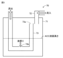
- FIG. 3 is a diagram for explaining the internal configuration of the accumulator 70 according to the first embodiment.
- the accumulator 70 includes a container 71, an inlet pipe 72, and an outlet pipe 73.
- the inlet pipe 72 is configured to be connectable to the pipe 18 connected to the evaporator side, and introduces the refrigerant flowing from the evaporator via the pipe 18 into the container 71.
- the liquid refrigerant is stored in the lower part of the container 71, and the gas refrigerant is retained in the upper part of the container 71.
- the outflow pipe 73 is configured to be connectable to the piping 19 connected to the compressor 30 side, and introduces the refrigerant accumulated in the container 71 into the suction port 31 of the compressor 30 through the piping 19.
- the outflow pipe 73 is formed in a U-shape and has a gas suction port 73a that draws in the gas refrigerant accumulated in the upper part of the container 71 and a liquid suction port 73b that draws in the liquid refrigerant accumulated in the lower part of the container 71.
- the gas refrigerant drawn in from the gas suction port 73a flows out through the outflow pipe 73 to the suction port 31 of the compressor 30.
- the liquid refrigerant drawn in from the liquid suction port 73b flows out through the outflow pipe 73 to the suction port 31 of the compressor 30.
- the diameter of the liquid suction port 73b is smaller than the diameter of the outflow pipe 73, so the amount of liquid refrigerant drawn in from the liquid suction port 73b is extremely small.
- the accumulator 70 configured as described above accumulates the liquid refrigerant in the lower part of the container 71, while retaining the gas refrigerant in the upper part of the container 71, among the refrigerant flowing from the evaporator via the pipe 18, thereby separating the refrigerant flowing through the refrigerant circuit 200 into liquid refrigerant and gas refrigerant, and storing the liquid refrigerant in the container 71.
- the liquid refrigerant accumulated in the container 71 flows into the outflow pipe 73 little by little through the liquid suction port 73b arranged in the liquid refrigerant, and is returned to the suction port 31 of the compressor 30 through the outflow pipe 73.
- the accumulator 70 will be abbreviated to "ACC.”
- the height of the liquid refrigerant stored in the container 71 of the accumulator 70 will be referred to as the “ACC liquid level height.”
- the amount of liquid refrigerant stored in the container 71 of the accumulator 70 will be referred to as the “ACC liquid refrigerant amount.”
- the return of the liquid refrigerant stored in the container 71 to the outflow pipe 73 via the liquid suction port 73b will be referred to as "liquid return.”
- a worker may fill the refrigerant circuit 200 with refrigerant, or may fill the refrigerant circuit 200 of an air conditioner 1 that has already been installed with additional refrigerant. At this time, the worker can determine whether or not an appropriate amount of refrigerant has been filled into the refrigerant circuit 200 by checking the amount of liquid refrigerant stored in the accumulator 70. In addition, in an installed air conditioner 1, a worker can determine whether or not a refrigerant leak is occurring in the refrigerant circuit 200 by checking the amount of liquid refrigerant stored in the accumulator 70. In this way, when installing or inspecting the air conditioner 1, the worker needs to check the amount of liquid refrigerant stored in the accumulator 70.
- one method for checking the amount of liquid refrigerant stored in the accumulator 70 is to heat the accumulator 70 with a heater (not shown) and measure the surface temperature of the accumulator 70 with multiple temperature sensors (not shown) installed in the height direction of the accumulator 70, thereby detecting the ACC liquid level based on the difference in temperature change according to the refrigerant state inside the accumulator 70.
- this method requires a heater and multiple temperature sensors to be specially installed in the accumulator 70, which increases costs.
- the air conditioner 1 is configured to perform a refrigerant amount detection process to more inexpensively check the amount of liquid refrigerant stored in the accumulator 70.
- FIG. 4 is a timing chart for explaining the state change of the refrigeration cycle when the air conditioner 1 according to the first embodiment executes the refrigerant amount detection process.
- the state change of the refrigeration cycle is shown when the refrigerant amount detection process is executed in the heating operation mode.
- the control device 100 controls the refrigerant circuit 200 in the first operation mode after startup, and then controls the refrigerant circuit 200 in the second operation mode.
- FIG. 4(A) shows how the drive frequency of the compressor 30 (hereinafter also referred to as the “compressor frequency”), the number of revolutions per unit time of the outdoor fan 51 (hereinafter also referred to as the “outdoor fan rotation speed”), and the opening degree of the indoor expansion valve 65 (hereinafter also referred to as the “LEV opening degree”) change during startup, in the first operating mode, and in the second operating mode.
- the compressor frequency, the outdoor fan rotation speed, and the LEV opening degree are controlled by the control device 100.
- Figure 4 (B) shows how the degree of subcooling at the condenser outlet (hereinafter also referred to as "condenser outlet SC”), the degree of superheat at the ACC inlet (hereinafter also referred to as “ACC inlet SH”), and the degree of superheat at the ACC outlet (hereinafter also referred to as “ACC outlet SH”) change during startup, the first operating mode, and the second operating mode.
- condenser outlet SC the degree of subcooling at the condenser outlet
- ACC inlet SH degree of superheat at the ACC inlet
- ACC outlet SH degree of superheat at the ACC outlet
- the condenser outlet SC can be calculated by subtracting the refrigerant temperature at the condenser outlet from the condensation temperature.
- the control device 100 acquires the pressure P2 of the refrigerant discharged from the compressor 30 from the pressure sensor 82, and calculates the saturation temperature of the refrigerant as the condensation temperature based on the acquired refrigerant pressure P2.
- the control device 100 acquires the temperature T4 of the refrigerant flowing out from the indoor heat exchanger 60, which serves as the condenser, from the temperature sensor 94.
- the control device 100 can calculate the condenser outlet SC by subtracting the refrigerant temperature T4 from the saturation temperature calculated as the condensation temperature.
- the ACC inlet SH can be calculated by subtracting the evaporation temperature from the refrigerant temperature at the ACC inlet.
- the control device 100 acquires the temperature T1 of the refrigerant flowing into the accumulator 70 from a temperature sensor 91.
- the control device 100 acquires the pressure P1 of the refrigerant flowing out from the exterior heat exchanger 50, which is an evaporator, from a pressure sensor 81, and calculates the saturation temperature of the refrigerant as the evaporation temperature based on the acquired refrigerant pressure P1.
- the control device 100 can calculate the ACC inlet SH by subtracting the evaporation temperature calculated based on the refrigerant pressure P1 from the refrigerant temperature T1.
- the ACC inlet SH is an example of a "first degree of superheat.”
- the ACC outlet SH can be calculated by subtracting the evaporation temperature from the refrigerant temperature at the ACC outlet.
- the control device 100 acquires the temperature T2 of the refrigerant flowing out of the accumulator 70 from the temperature sensor 92.
- the control device 100 acquires the pressure P1 of the refrigerant flowing out from the exterior heat exchanger 50, which is an evaporator, from the pressure sensor 81, and calculates the saturation temperature of the refrigerant as the evaporation temperature based on the acquired refrigerant pressure P1.
- the control device 100 can calculate the ACC outlet SH by subtracting the evaporation temperature calculated based on the refrigerant pressure P1 from the refrigerant temperature T2.
- the ACC outlet SH is an example of the "second degree of superheat".
- Figure 4(C) shows how the evaporating temperature and condensing temperature change during startup, during the first operating mode, and during the second operating mode.
- Figure 4(D) shows how the amount of ACC liquid refrigerant changes during startup, during the first operating mode, and during the second operating mode.
- the air conditioner 1 when the control device 100 controls the refrigerant circuit 200 in the first operation mode, the refrigeration cycle is in a steady state. Specifically, as shown in FIG. 4(A), in the first operation mode, the air conditioner 1 fixes the compressor frequency at a predetermined value so that the condensation temperature is constant, fixes the outdoor fan rotation speed at a predetermined value so that the evaporation temperature is constant, and further fixes the LEV opening at a predetermined value so that the condenser outlet SC is constant. As shown in FIG. 4(B), in such a first operation mode, the difference between the ACC inlet SH and the ACC outlet SH (hereinafter also referred to as the "SH difference”) is less than a predetermined value (for example, a value greater than 0).
- a predetermined value for example, a value greater than 0
- the SH difference is 0 or approximately 0.
- the ACC inlet SH and the ACC outlet SH are the same or approximately the same.
- the ACC liquid refrigerant amount is also in a state that does not change substantially.
- the air conditioner 1 cannot detect the ACC liquid refrigerant amount even if it uses the pressure and temperature of the refrigerant entering and leaving the accumulator 70, i.e., the refrigerant pressure P1 and the refrigerant temperatures T1 and T2.
- control device 100 controls the refrigerant circuit 200 in the first operation mode to bring the refrigeration cycle into a steady state, and then controls the refrigerant circuit 200 in the second operation mode to deliberately change the state of the refrigeration cycle and bring it into a transient state.
- the air conditioner 1 changes the compressor frequency in the second operation mode, making the compressor frequency in the second operation mode smaller than the compressor frequency in the first operation mode. For example, the air conditioner 1 minimizes the compressor frequency in the second operation mode.
- the air conditioner 1 changes the LEV opening in the second operation mode, making the LEV opening in the second operation mode smaller than the LEV opening in the first operation mode.
- the air conditioner 1 does not change the outdoor fan rotation speed in the second operation mode, making the airflow rate of the outdoor fan 51 in the second operation mode the same as the airflow rate of the outdoor fan 51 in the first operation mode.
- the outdoor fan rotation speed in this case may be the maximum rotation speed.
- the ACC inlet SH becomes larger than the ACC outlet SH, and an SH difference occurs.
- the SH difference becomes equal to or greater than a predetermined value (for example, a value greater than 0).
- the amount of ACC liquid refrigerant decreases.
- the mixed refrigerant which is a mixture of the gas refrigerant sucked in from the gas suction port 73a and the liquid refrigerant sucked in from the liquid suction port 73b due to liquid return, flows through the outflow pipe 73 and flows out to the compressor 30.
- the temperature of the mixed refrigerant decreases as the liquid refrigerant, which has a lower temperature than the gas refrigerant, mixes with the gas refrigerant.
- the refrigerant temperature at the ACC outlet drops from a value corresponding to point d1 to a value corresponding to point d2 or point d3 depending on the amount of liquid refrigerant returning.
- the air conditioner 1 in the second operation mode by controlling the air conditioner 1 in the second operation mode, a difference can be generated between the refrigerant temperature at the ACC inlet and the refrigerant temperature at the ACC outlet depending on the amount of liquid refrigerant returning, i.e., the ACC liquid level height.
- the ACC inlet SH can be calculated by subtracting the evaporation temperature from the refrigerant temperature at the ACC inlet
- the ACC outlet SH can be calculated by subtracting the evaporation temperature from the refrigerant temperature at the ACC outlet.
- the SH difference between the ACC inlet SH and the ACC outlet SH is proportional to the difference between the refrigerant temperature T1 at the ACC inlet and the refrigerant temperature T2 at the ACC outlet. Therefore, as shown in FIG. 4(B), when the air conditioner 1 is controlled in the second operation mode, the SH difference is generated by the difference between the refrigerant temperature T1 at the ACC inlet and the refrigerant temperature T2 at the ACC outlet.
- Figure 5 is a graph showing the change in the liquid level of the liquid refrigerant in the accumulator 70 (ACC liquid level) relative to the difference (SH difference) between the degree of superheat of the refrigerant flowing into the accumulator 70 (ACC inlet SH) and the degree of superheat of the refrigerant flowing out of the accumulator 70 (ACC outlet SH).
- such a change in the ACC liquid level height in response to the SH difference differs depending on the compressor frequency. Specifically, the lower the compressor frequency, the smaller the change in the ACC liquid level height in response to the SH difference. Since the ACC liquid level height has an upper limit depending on the capacity of the container 71, the lower the compressor frequency, the wider the detection range for the change in the ACC liquid level height in response to the SH difference can be secured.
- the change in ACC liquid level relative to the SH difference is smaller than when the compressor frequency is f2, which is greater than f1.
- the compressor frequency is f2
- the ACC liquid level can only be detected when the SH difference is between 0 and 6°C
- the compressor frequency is f1
- the ACC liquid level can be detected when the SH difference is between 0 and 10°C.
- the air conditioner 1 reduces the compressor frequency in the second operating mode, the compressor frequency is minimized, thereby ensuring a wider detection range for the change in ACC liquid level height relative to the SH difference.
- the control device 100 controls the refrigerant circuit 200 in the second operation mode to generate an SH difference, and then detects the ACC liquid level from the SH difference by referring to data on the change in the ACC liquid level relative to the SH difference as shown in FIG. 5.
- the control device 100 can calculate the amount of liquid refrigerant stored in the container 71 of the accumulator 70 based on the detected ACC liquid level and the shape or volume of the container 71 pre-stored in the memory unit 102.
- control device 100 is configured to calculate the amount of liquid refrigerant remaining in the condenser other than the liquid refrigerant stored in the accumulator 70 based on the liquid phase area ratio A L %.
- the liquid phase area ratio A L % is the liquid phase volume ratio in the total volume of the condenser, and is an index obtained by correcting the condenser outlet SC with the outside air temperature, the discharge enthalpy of the compressor 30, and the low-pressure liquid specific heat of the refrigerant. Specifically, the control device 100 calculates the liquid phase area ratio A L % using the following formula (1).
- a L % -Ln (1 - SC / dT c ) * dT c * C Pr / ⁇ h con ... (1)
- SC is the condenser outlet SC.
- dTc is the difference between the outside air temperature T5 measured by the temperature sensor 95 and the condensation temperature.
- CPr is the constant pressure liquid specific heat of the refrigerant.
- ⁇ hcon is the difference between the enthalpy of the refrigerant at the condenser inlet and the enthalpy of the refrigerant at the condenser outlet.
- the control device 100 can calculate the amount of liquid refrigerant stored in the condenser based on the liquid phase area ratio A L % calculated using formula (1) and the shape or volume of the condenser pre-stored in the memory unit 102. For details about the liquid phase area ratio A L %, see Japanese Patent No. 5,063,346.
- control device 100 calculates the amount of liquid refrigerant stored in the accumulator 70, calculates the amount of liquid refrigerant stored in the condenser, and adds the amount of liquid refrigerant stored in the accumulator 70 and the amount of liquid refrigerant stored in the condenser to calculate the total amount of liquid refrigerant remaining in the refrigerant circuit 200. Note that in the evaporator, the refrigerant is gasified and flows into the accumulator 70, so no liquid refrigerant remains.
- the control device 100 transmits liquid refrigerant amount data to the user device 500, which indicates the calculated amount of liquid refrigerant stored in the accumulator 70, the calculated amount of liquid refrigerant stored in the condenser, or the total amount of liquid refrigerant remaining in the refrigerant circuit 200.
- the user device 500 notifies a user, such as an operator, of the calculated amount of liquid refrigerant stored in the accumulator 70, the calculated amount of liquid refrigerant stored in the condenser, or the total amount of liquid refrigerant remaining in the refrigerant circuit 200, based on the liquid refrigerant amount data acquired from the control device 100, using a display or the like.
- the air conditioner 1 can calculate the amount of liquid refrigerant stored by the accumulator 70 based on the SH difference between the ACC inlet SH and the ACC outlet SH, and notify the worker of the calculated amount of liquid refrigerant, allowing the worker to check the amount of liquid refrigerant stored in the accumulator 70 at a lower cost.
- FIG. 6 is a flowchart for explaining the refrigerant amount detection process executed by the air conditioner 1 according to embodiment 1.
- the control device 100 executes the refrigerant amount detection process of the flowchart shown in Figure 6, for example, by executing a program stored in the memory unit 102. Note that in the figure, "S" is used as an abbreviation for "STEP.”
- the control device 100 starts up various devices included in the refrigerant circuit 200 of the air conditioner 1 (S1), and executes processing related to the first operation mode. Specifically, the control device 100 changes the compressor frequency by controlling the compressor 30 (S2). The control device 100 changes the outdoor fan rotation speed by controlling the outdoor fan 51 (S3). The control device 100 changes the LEV opening by controlling the indoor expansion valve 65 (S4).
- the control device 100 determines whether the condenser outlet SC is at a predetermined value (S5). If the condenser outlet SC is not at the predetermined value (NO in S5), the control device 100 changes the LEV opening by controlling the indoor expansion valve 65 again (S4).
- the control device 100 determines whether the evaporation temperature is at a predetermined value (S6). If the evaporation temperature is not at a predetermined value (NO in S6), the control device 100 changes the outdoor fan rotation speed by controlling the outdoor fan 51 again (S3).
- the control device 100 judges whether the condensation temperature is the predetermined value (S7).
- the control device 100 controls the compressor 30 again to change the compressor frequency (S2).
- the control device 100 can bring the refrigeration cycle into a steady state as shown in FIG. 4 by the above-mentioned processes in S2 to S7 related to the first operation mode.
- the control device 100 calculates the liquid phase area ratio A L % (S8). This allows the control device 100 to calculate the amount of liquid refrigerant stored in the condenser.
- control device 100 executes processing related to the second operation mode. Specifically, the control device 100 starts counting a predetermined time for executing processing related to the second operation mode (S9).
- the control device 100 changes the LEV opening by controlling the indoor expansion valve 65, making the LEV opening in the second operation mode smaller than the LEV opening in the first operation mode (S10).
- the control device 100 controls the compressor 30 to change the compressor frequency, and makes the compressor frequency in the second operation mode smaller than the compressor frequency in the first operation mode (S11). For example, the control device 100 controls the compressor 30 to minimize the compressor frequency.
- the control device 100 fixes the outdoor fan rotation speed at a predetermined value and sets the airflow rate of the outdoor fan 51 in the second operation mode to the same as the airflow rate of the outdoor fan 51 in the first operation mode (S12).
- the control device 100 calculates the SH difference while the SH difference is being generated as shown in FIG. 4 by the processing related to the second operation mode of S10 to S12 described above (S14).
- the control device 100 calculates the amount of liquid refrigerant stored in the accumulator 70 based on the calculated SH difference (S15). Specifically, the control device 100 stores data on the change in the ACC liquid level height relative to the SH difference as shown in FIG. 5 in advance in the memory unit 102, and calculates the ACC liquid level height based on the data and the calculated SH difference. Furthermore, the control device 100 calculates the amount of liquid refrigerant stored in the accumulator 70 based on the calculated ACC liquid level height and the shape or volume of the container 71 that is stored in advance in the memory unit 102.
- the control device 100 transmits liquid refrigerant amount data indicating the calculated amount of liquid refrigerant stored in the accumulator 70, the amount of liquid refrigerant stored in the condenser, or the total amount of liquid refrigerant remaining in the refrigerant circuit 200 to the user device 500 (S16). This allows an operator to check the amount of liquid refrigerant stored in the accumulator 70 using the user device 500.
- the control device 100 determines whether the time since the counting was started in S9 has passed a predetermined time (S17). If the time since the counting was started in S9 has not passed the predetermined time (NO in S17), the control device 100 returns to S14 and calculates the SH difference again (S14). On the other hand, if the time since the counting was started in S9 has passed the predetermined time (YES in S17), the control device 100 ends this process. Note that the control device 100 is not limited to calculating the liquid phase area ratio A L % in S8, and may calculate the liquid phase area ratio A L % before S14 or after S15, for example.
- the air conditioner 1 is able to calculate the amount of liquid refrigerant stored in the accumulator 70 based on the SH difference between the ACC inlet SH and the ACC outlet SH, and notify the worker of the calculated amount of liquid refrigerant, allowing the worker to check the amount of liquid refrigerant stored in the accumulator 70 at a lower cost.
- Embodiment 2 An air conditioner 1 according to embodiment 2 will be described with reference to Fig. 7. In the following, the contents of the air conditioner 1 according to embodiment 2 will be described with the same reference numerals used for configurations that are the same as those in the air conditioner 1 according to embodiment 1, and with different reference numerals used for configurations that are different from those in the air conditioner 1 according to embodiment 1.
- FIG. 7 is a diagram showing the configuration of an air conditioner 1 and an air conditioning system 1000 according to embodiment 2. As shown in FIG. 7, the air conditioner 1 according to embodiment 2 further includes an outdoor expansion valve 55.
- the outdoor expansion valve 55 is, for example, an electronic expansion valve whose opening is adjusted according to the control of the control device 100.
- the outdoor expansion valve 55 reduces the pressure of the refrigerant that flows in, and the refrigerant obtained by the reduced pressure flows out.
- the control device 100 can adjust the amount of pressure reduction of the refrigerant by adjusting the opening of the outdoor expansion valve 55.
- One end of the outdoor expansion valve 55 is connected to the indoor unit 400 via the piping 16 and the extension piping 22.
- the other end of the outdoor expansion valve 55 is connected to the outdoor heat exchanger 50 via the piping 20.
- the control device 100 controls the outdoor expansion valve 55 instead of the indoor expansion valve 65, thereby making the opening degree of the outdoor expansion valve 55 in the second operation mode smaller than the opening degree of the outdoor expansion valve 55 in the first operation mode. In this way, even when the opening degree of the outdoor expansion valve 55 is narrowed, the control device 100 can reduce the amount of refrigerant flowing to the evaporator, and as a result, the ACC inlet SH can be made larger than the ACC outlet SH to generate an SH difference.
- the control device 100 only needs to reduce the opening degree of at least one of the indoor expansion valve 65 and the outdoor expansion valve 55. That is, in the second operation mode, the control device 100 may reduce the opening degree of only the indoor expansion valve 65, may reduce the opening degree of only the outdoor expansion valve 55, or may reduce the opening degree of both the indoor expansion valve 65 and the outdoor expansion valve 55.
- Embodiment 3 An air conditioner 1 according to embodiment 3 will be described.
- the control device 100 fixes the outdoor fan rotation speed at a predetermined value in the second operation mode, and sets the airflow rate of the outdoor fan 51 in the second operation mode to be the same as the airflow rate of the outdoor fan 51 in the first operation mode.
- the control device 100 may increase the outdoor fan rotation speed in the second operation mode, and set the airflow rate of the outdoor fan 51 in the second operation mode to be greater than the airflow rate of the outdoor fan 51 in the first operation mode.
- control device 100 when the control device 100 makes the airflow rate of the outdoor fan 51 in the second operation mode larger than the airflow rate of the outdoor fan 51 in the first operation mode, it can further promote the gasification of the refrigerant flowing through the evaporator, and as a result, it can make the ACC inlet SH larger than the ACC outlet SH, making it easier to create an SH difference.
- Embodiment 4 An air conditioner 1 according to a fourth embodiment will be described.
- the control device 100 was configured to detect the ACC liquid level based on the SH difference generated in the second operation mode.
- the ACC inlet SH can be calculated by subtracting the evaporation temperature from the refrigerant temperature at the ACC inlet
- the ACC outlet SH can be calculated by subtracting the evaporation temperature from the refrigerant temperature at the ACC outlet.
- the SH difference between the ACC inlet SH and the ACC outlet SH is proportional to the difference between the refrigerant temperature T1 at the ACC inlet and the refrigerant temperature T2 at the ACC outlet.
- the control device 100 may detect the ACC liquid level based on the difference between the refrigerant temperature T1 at the ACC inlet and the refrigerant temperature T2 at the ACC outlet. Specifically, by replacing the SH difference on the horizontal axis in the data shown in FIG. 5 with the difference between the refrigerant temperature T1 at the ACC inlet and the refrigerant temperature T2 at the ACC outlet, the control device 100 can obtain data on the change in the ACC liquid level relative to the difference between the refrigerant temperature T1 at the ACC inlet and the refrigerant temperature T2 at the ACC outlet. The control device 100 may use such data to detect the ACC liquid level based on the difference between the refrigerant temperature T1 at the ACC inlet and the refrigerant temperature T2 at the ACC outlet.
- the refrigerant amount detection process executed by the air conditioner 1 according to the above-mentioned embodiments 1 to 4 can be executed not only in the heating operation mode but also in the cooling operation mode.
- the temperature sensor 92 provided between the outlet side of the accumulator 70 and the intake port 31 of the compressor 30 is illustrated as the "second temperature sensor” that measures the temperature of the refrigerant flowing out of the accumulator 70, but a temperature sensor provided in another position may be applied to the "second temperature sensor".
- the temperature sensor 93 may be applied to the "second temperature sensor” and the refrigerant temperature T3 may be applied to the "second measurement result". In this case, the temperature sensor 92 does not need to be installed.
- the compressor 30 has a structure in which the compression mechanism is built into a sealed container filled with the intake refrigerant or discharge refrigerant, a temperature sensor (not shown) that detects the surface temperature of the sealed container may be used as the "second temperature sensor,” and the surface temperature of the sealed container may be used as the "second measurement result.” Note that since the sealed container of the compressor 30 is filled with the refrigerant flowing out from the accumulator 70, the surface temperature of the sealed container of the compressor 30 corresponds to the temperature of the refrigerant flowing out from the accumulator 70.
- the air conditioner 1 of the present disclosure includes a refrigerant circuit 200 including a compressor 30, a condenser (for example, an indoor heat exchanger 60), at least one expansion valve (for example, an indoor expansion valve 65, an outdoor expansion valve 55), and an evaporator (for example, an outdoor heat exchanger 50) and configured to circulate a refrigerant, a control device 100 for controlling the refrigerant circuit 200, an accumulator 70 for separating the refrigerant flowing through the refrigerant circuit 200 into a liquid refrigerant and a gas refrigerant and storing the liquid refrigerant, a temperature sensor 91 for measuring a temperature T1 of the refrigerant flowing into the accumulator 70, and a temperature sensor 92 for measuring a temperature T2 of the refrigerant flowing out of the accumulator 70.
- a control device 100 for controlling the refrigerant circuit 200
- an accumulator 70 for separating the refrigerant flowing through the refrigerant circuit 200 into a liquid refrig
- the accumulator 70 is disposed between the compressor 30 and the evaporator.
- the control device 100 calculates the amount of liquid refrigerant stored by the accumulator 70 based on the refrigerant temperature T1 measured by the temperature sensor 91 and the refrigerant temperature T2 measured by the temperature sensor 92.
- the air conditioner 1 can calculate the amount of liquid refrigerant stored in the accumulator 70 based on the temperature T1 of the refrigerant flowing into the accumulator 70 and the temperature T2 of the refrigerant flowing out of the accumulator 70, allowing workers to more inexpensively check the amount of liquid refrigerant stored in the accumulator 70.
- the control device 100 calculates the amount of liquid refrigerant stored by the accumulator 70 based on the difference between the temperature T1 of the refrigerant flowing into the accumulator 70 and the temperature T2 of the refrigerant flowing out of the accumulator 70.
- the air conditioner 1 can calculate the amount of liquid refrigerant stored in the accumulator 70 based on the difference between the temperature T1 of the refrigerant flowing into the accumulator 70 and the temperature T2 of the refrigerant flowing out of the accumulator 70, allowing workers to more inexpensively check the amount of liquid refrigerant stored in the accumulator 70.
- the air conditioner 1 further includes a pressure sensor 81 that measures the pressure P1 of the refrigerant flowing into the accumulator 70.
- the control device 100 calculates the degree of superheat (ACC inlet SH) of the refrigerant flowing into the accumulator 70 based on the refrigerant pressure P1 measured by the pressure sensor 81 and the temperature T1 of the refrigerant flowing into the accumulator 70, calculates the degree of superheat (ACC outlet SH) of the refrigerant flowing out of the accumulator 70 based on the refrigerant pressure P1 measured by the pressure sensor 81 and the temperature T2 of the refrigerant flowing out of the accumulator 70, and calculates the amount of liquid refrigerant stored by the accumulator 70 based on the SH difference between the ACC inlet SH and the ACC outlet SH.
- the air conditioner 1 can calculate the amount of liquid refrigerant stored in the accumulator 70 based on the SH difference between the ACC inlet SH and the ACC outlet SH, allowing workers to more inexpensively check the amount of liquid refrigerant stored in the accumulator 70.
- the control device 100 controls the refrigerant circuit 200 in a first operation mode in which the SH difference between the ACC inlet SH and the ACC outlet SH is less than a predetermined value, and then controls the refrigerant circuit 200 in a second operation mode in which the SH difference between the ACC inlet SH and the ACC outlet SH is equal to or greater than a predetermined value, and calculates the amount of liquid refrigerant stored by the accumulator 70 in the second operation mode.
- the air conditioner 1 can generate an SH difference between the ACC inlet SH and the ACC outlet SH by controlling the refrigerant circuit 200 in the second operation mode to put the refrigeration cycle into a transient state. This allows the air conditioner 1 to detect the amount of liquid refrigerant stored in the accumulator 70 using the SH difference generated in the second operation mode.
- the control device 100 makes the opening degree of at least one expansion valve (e.g., indoor expansion valve 65, outdoor expansion valve 55) in the second operation mode smaller than the opening degree of at least one expansion valve (e.g., indoor expansion valve 65, outdoor expansion valve 55) in the first operation mode.
- at least one expansion valve e.g., indoor expansion valve 65, outdoor expansion valve 55
- the air conditioner 1 can reduce the amount of refrigerant flowing to the evaporator by narrowing the opening of at least one expansion valve (for example, the indoor expansion valve 65, the outdoor expansion valve 55), and as a result, the ACC inlet SH can be made larger than the ACC outlet SH to create an SH difference.
- at least one expansion valve for example, the indoor expansion valve 65, the outdoor expansion valve 55
- At least one expansion valve is an indoor expansion valve 65 arranged in the indoor unit 400 or an outdoor expansion valve 55 arranged in the outdoor unit 300.
- the air conditioner 1 can reduce the amount of refrigerant flowing to the evaporator by narrowing the opening of at least one of the indoor expansion valve 65 and the outdoor expansion valve 55, and as a result, the ACC inlet SH can be made larger than the ACC outlet SH to create an SH difference.
- the air conditioner 1 further includes a fan (e.g., outdoor fan 51) that sends air to the evaporator.
- the control device 100 sets the airflow rate of the fan in the second operation mode to the same as the airflow rate of the fan in the first operation mode.
- the air conditioner 1 can reduce the amount of refrigerant flowing to the evaporator by narrowing the opening of at least one expansion valve (e.g., indoor expansion valve 65, outdoor expansion valve 55) and maintaining the airflow of the fan (e.g., outdoor fan 51) that sends air to the evaporator, and as a result, the ACC inlet SH can be made larger than the ACC outlet SH to create an SH difference.
- at least one expansion valve e.g., indoor expansion valve 65, outdoor expansion valve 55
- the fan e.g., outdoor fan 51
- the air conditioner 1 further includes a fan (e.g., outdoor fan 51) that sends air to the evaporator.
- the control device 100 makes the airflow rate of the fan in the second operation mode greater than the airflow rate of the fan in the first operation mode.
- the air conditioner 1 can reduce the amount of refrigerant flowing to the evaporator by narrowing the opening of at least one expansion valve (e.g., indoor expansion valve 65, outdoor expansion valve 55) and increasing the airflow rate of the fan (e.g., outdoor fan 51) that sends air to the evaporator, and as a result, the ACC inlet SH can be made larger than the ACC outlet SH to create an SH difference.
- at least one expansion valve e.g., indoor expansion valve 65, outdoor expansion valve 55
- the fan e.g., outdoor fan 51
- the control device 100 makes the frequency of the compressor 30 in the second operating mode lower than the frequency of the compressor 30 in the first operating mode.
- the air conditioner 1 can promote gasification of the refrigerant in the evaporator by making the frequency of the compressor 30 in the second operation mode lower than the frequency of the compressor 30 in the first operation mode, and as a result, the ACC inlet SH can be made higher than the ACC outlet SH to generate an SH difference. Furthermore, as shown in FIG. 5, the air conditioner 1 can ensure a larger detection range for the change in ACC liquid level height relative to the SH difference as the frequency of the compressor 30 in the second operation mode is made lower.
- the air conditioning system 1000 disclosed herein includes the air conditioner 1 described above, and a user device 500 that notifies the user of the amount of liquid refrigerant stored in the accumulator 70, which is calculated by the air conditioner 1.
- the air conditioning system 1000 can notify the operator of the amount of liquid refrigerant stored in the accumulator 70 calculated by the air conditioner 1 via the user device 500, improving convenience for the operator.
- Air conditioner 11, 12, 13, 14, 15, 16, 17, 18, 19, 20 Piping, 21, 22 Extension piping, 30 Compressor, 31 Intake port, 32 Discharge port, 40 Four-way valve, 41, 42, 43, 44 Connection port, 50 Outdoor heat exchanger, 51 Outdoor fan, 55 Outdoor expansion valve, 60 Indoor heat exchanger, 61 Indoor fan, 65 Indoor expansion valve, 70 Accumulator, 71 container, 72 inlet pipe, 73 outlet pipe, 73a gas inlet, 73b liquid inlet, 81, 82 pressure sensors, 91, 92, 93, 94, 95 temperature sensors, 100 control device, 101 control unit, 102 memory unit, 200 refrigerant circuit, 300 outdoor unit, 400 indoor unit, 500 user device, 1000 air conditioning system.
Landscapes
- Engineering & Computer Science (AREA)
- Physics & Mathematics (AREA)
- Mechanical Engineering (AREA)
- Thermal Sciences (AREA)
- General Engineering & Computer Science (AREA)
- Air Conditioning Control Device (AREA)
Abstract
Description
図1を参照しながら、実施の形態1に係る空気調和機1および空気調和システム1000について説明する。図1は、施の形態1に係る空気調和機1および空気調和システム1000の構成を示す図である。なお、図1では、空気調和機1における各機器の接続関係および配置構成を機能的に示しており、物理的な空間における配置を必ずしも示すものではない。
AL%=-Ln(1-SC/dTc)*dTc*CPr/Δhcon…(1)
式(1)において、SCは、凝縮器出口SCである。dTcは、温度センサ95によって測定された外気温度T5と凝縮温度との差である。CPrは、冷媒の定圧液比熱である。Δhconは、凝縮器入口の冷媒におけるエンタルピと、凝縮器出口の冷媒におけるエンタルピとの差である。
制御装置100は、上述したS2~S7の第1運転モードに係る処理によって、図4に示すように、冷凍サイクルを定常状態にすることができる。
図7を参照しながら、実施の形態2に係る空気調和機1を説明する。以下では、実施の形態2に係る空気調和機1について、実施の形態1に係る空気調和機1と同じ構成については同じ符号を付し、実施の形態1に係る空気調和機1と異なる構成ついては異なる符号を付して以下にその内容を説明する。
実施の形態3に係る空気調和機1を説明する。実施の形態1に係る空気調和機1において、制御装置100は、第2運転モードにおいて、室外ファン回転数を所定値で固定し、第2運転モードにおける室外ファン51の送風量を、第1運転モードにおける室外ファン51の送風量と同じにしていた。実施の形態3に係る空気調和機1においては、制御装置100は、第2運転モードにおいて、室外ファン回転数を上げて、第2運転モードにおける室外ファン51の送風量を、第1運転モードにおける室外ファン51の送風量よりも大きくしてもよい。
実施の形態4に係る空気調和機1を説明する。実施の形態1に係る空気調和機1において、制御装置100は、第2運転モードにおいて生じたSH差に基づき、ACC液面高さを検出するように構成されていた。ここで、ACC入口SHは、ACC入口の冷媒温度から蒸発温度を減算することで算出可能であり、ACC出口SHは、ACC出口の冷媒温度から蒸発温度を減算することで算出可能である。ACC入口SHとACC出口SHとで、算出時に用いる蒸発温度が同じであることに鑑みれば、ACC入口SHとACC出口SHとのSH差は、ACC入口の冷媒温度T1とACC出口の冷媒温度T2との差に比例する。
本開示の空気調和機1は、圧縮機30、凝縮器(たとえば、室内熱交換器60)、少なくとも1つの膨張弁(たとえば、室内膨張弁65,室外膨張弁55)、および蒸発器(たとえば、室外熱交換器50)を備え、冷媒を循環させるように構成された冷媒回路200と、冷媒回路200を制御する制御装置100と、冷媒回路200を流れる冷媒を液冷媒とガス冷媒とに分離させ、液冷媒を貯留するアキュムレータ70と、アキュムレータ70に流入する冷媒の温度T1を測定する温度センサ91と、アキュムレータ70から流出する冷媒の温度T2を測定する温度センサ92とを備える。アキュムレータ70は、圧縮機30と蒸発器との間に配置されている。制御装置100は、温度センサ91の測定結果である冷媒温度T1と、温度センサ92の測定結果である冷媒温度T2とに基づき、アキュムレータ70によって貯留された液冷媒の量を算出する。
Claims (10)
- 圧縮機、凝縮器、少なくとも1つの膨張弁、および蒸発器を備え、冷媒を循環させるように構成された冷媒回路と、
前記冷媒回路を制御する制御装置と、
前記冷媒回路を流れる冷媒を液冷媒とガス冷媒とに分離させ、前記液冷媒を貯留するアキュムレータと、
前記アキュムレータに流入する前記冷媒の温度を測定する第1温度センサと、
前記アキュムレータから流出する前記冷媒の温度を測定する第2温度センサとを備え、
前記アキュムレータは、前記圧縮機と前記蒸発器との間に配置され、
前記制御装置は、前記第1温度センサの第1測定結果と、前記第2温度センサの第2測定結果とに基づき、前記アキュムレータによって貯留された前記液冷媒の量を算出する、空気調和機。 - 前記制御装置は、前記第1測定結果と前記第2測定結果との差に基づき、前記アキュムレータによって貯留された前記液冷媒の量を算出する、請求項1に記載の空気調和機。
- 前記アキュムレータに流入する前記冷媒の圧力を測定する圧力センサをさらに備え、
前記制御装置は、
前記圧力センサの測定結果と前記第1測定結果とに基づき、前記アキュムレータに流入する前記冷媒の第1過熱度を算出し、
前記圧力センサの測定結果と前記第2測定結果とに基づき、前記アキュムレータから流出する前記冷媒の第2過熱度を算出し、
前記第1過熱度と前記第2過熱度との差に基づき、前記アキュムレータによって貯留された前記液冷媒の量を算出する、請求項2に記載の空気調和機。 - 前記制御装置は、
前記第1過熱度と前記第2過熱度との差を所定値未満にする第1運転モードで前記冷媒回路を制御した後、前記第1過熱度と前記第2過熱度との差を前記所定値以上にする第2運転モードで前記冷媒回路を制御し、
前記第2運転モードにおいて、前記アキュムレータによって貯留された前記液冷媒の量を算出する、請求項3に記載の空気調和機。 - 前記制御装置は、前記第2運転モードにおける前記少なくとも1つの膨張弁の開度を、前記第1運転モードにおける前記少なくとも1つの膨張弁の開度よりも小さくする、請求項4に記載の空気調和機。
- 前記少なくとも1つの膨張弁は、室内機に配置された室内膨張弁または室外機に配置された室外膨張弁である、請求項5に記載の空気調和機。
- 前記蒸発器に空気を送るファンをさらに備え、
前記制御装置は、前記第2運転モードにおける前記ファンの送風量を、前記第1運転モードにおける前記ファンの送風量と同じにする、請求項5に記載の空気調和機。 - 前記蒸発器に空気を送るファンをさらに備え、
前記制御装置は、前記第2運転モードにおける前記ファンの送風量を、前記第1運転モードにおける前記ファンの送風量よりも大きくする、請求項5に記載の空気調和機。 - 前記制御装置は、前記第2運転モードにおける前記圧縮機の周波数を、前記第1運転モードにおける前記圧縮機の周波数よりも小さくする、請求項5~請求項8のいずれか1項に記載の空気調和機。
- 請求項1~請求項9のいずれか1項に記載の前記空気調和機と、
前記空気調和機によって算出された前記アキュムレータによって貯留された前記液冷媒の量を報知するユーザ装置とを備える、空気調和システム。
Priority Applications (4)
| Application Number | Priority Date | Filing Date | Title |
|---|---|---|---|
| JP2024562417A JPWO2024121908A1 (ja) | 2022-12-05 | 2022-12-05 | |
| PCT/JP2022/044759 WO2024121908A1 (ja) | 2022-12-05 | 2022-12-05 | 空気調和機および空気調和システム |
| DE112022008079.5T DE112022008079T5 (de) | 2022-12-05 | 2022-12-05 | Klimaanlage und klimatisierungssystem |
| CN202280102245.8A CN120344806A (zh) | 2022-12-05 | 2022-12-05 | 空调机和空调系统 |
Applications Claiming Priority (1)
| Application Number | Priority Date | Filing Date | Title |
|---|---|---|---|
| PCT/JP2022/044759 WO2024121908A1 (ja) | 2022-12-05 | 2022-12-05 | 空気調和機および空気調和システム |
Publications (1)
| Publication Number | Publication Date |
|---|---|
| WO2024121908A1 true WO2024121908A1 (ja) | 2024-06-13 |
Family
ID=91378748
Family Applications (1)
| Application Number | Title | Priority Date | Filing Date |
|---|---|---|---|
| PCT/JP2022/044759 Ceased WO2024121908A1 (ja) | 2022-12-05 | 2022-12-05 | 空気調和機および空気調和システム |
Country Status (4)
| Country | Link |
|---|---|
| JP (1) | JPWO2024121908A1 (ja) |
| CN (1) | CN120344806A (ja) |
| DE (1) | DE112022008079T5 (ja) |
| WO (1) | WO2024121908A1 (ja) |
Citations (4)
| Publication number | Priority date | Publication date | Assignee | Title |
|---|---|---|---|---|
| JP2001027455A (ja) * | 1999-05-13 | 2001-01-30 | Denso Corp | ヒートポンプ式空調装置 |
| JP2009229050A (ja) * | 2008-02-29 | 2009-10-08 | Daikin Ind Ltd | 空気調和装置 |
| WO2013088590A1 (ja) * | 2011-12-12 | 2013-06-20 | 三菱電機株式会社 | 室外機及び空気調和装置 |
| WO2019064480A1 (ja) * | 2017-09-29 | 2019-04-04 | 三菱電機株式会社 | 液面検知装置、アキュムレータおよび空気調和機 |
-
2022
- 2022-12-05 CN CN202280102245.8A patent/CN120344806A/zh active Pending
- 2022-12-05 JP JP2024562417A patent/JPWO2024121908A1/ja active Pending
- 2022-12-05 DE DE112022008079.5T patent/DE112022008079T5/de active Pending
- 2022-12-05 WO PCT/JP2022/044759 patent/WO2024121908A1/ja not_active Ceased
Patent Citations (4)
| Publication number | Priority date | Publication date | Assignee | Title |
|---|---|---|---|---|
| JP2001027455A (ja) * | 1999-05-13 | 2001-01-30 | Denso Corp | ヒートポンプ式空調装置 |
| JP2009229050A (ja) * | 2008-02-29 | 2009-10-08 | Daikin Ind Ltd | 空気調和装置 |
| WO2013088590A1 (ja) * | 2011-12-12 | 2013-06-20 | 三菱電機株式会社 | 室外機及び空気調和装置 |
| WO2019064480A1 (ja) * | 2017-09-29 | 2019-04-04 | 三菱電機株式会社 | 液面検知装置、アキュムレータおよび空気調和機 |
Also Published As
| Publication number | Publication date |
|---|---|
| DE112022008079T5 (de) | 2025-10-02 |
| CN120344806A (zh) | 2025-07-18 |
| JPWO2024121908A1 (ja) | 2024-06-13 |
Similar Documents
| Publication | Publication Date | Title |
|---|---|---|
| JP4864110B2 (ja) | 冷凍空調装置 | |
| EP3859247B1 (en) | Air-conditioning device | |
| JP5791716B2 (ja) | 冷凍空調装置及び冷凍空調装置の制御方法 | |
| JP2011226704A (ja) | 冷凍空調装置並びに冷凍空調システム | |
| JP6902390B2 (ja) | 冷凍サイクル装置 | |
| Dechesne et al. | Residential air-source heat pump with refrigerant injection and variable speed compressor: Experimental investigation and compressor modeling | |
| CN104067070B (zh) | 制冷循环装置 | |
| JP2010065998A (ja) | パラメータを監視する方法及び冷却装置 | |
| CN114992798A (zh) | 一种空调系统及其室内机能力计算方法 | |
| JP2943613B2 (ja) | 非共沸混合冷媒を用いた冷凍空調装置 | |
| CN109073304B (zh) | 制冷装置 | |
| CN112739961B (zh) | 制冷循环装置的室外机、制冷循环装置以及空调装置 | |
| WO2024121908A1 (ja) | 空気調和機および空気調和システム | |
| CN107110586B (zh) | 制冷装置 | |
| JP6972370B2 (ja) | 冷凍サイクル装置 | |
| US12540740B2 (en) | Air conditioner, control method, and non-transitory computer-readable recording medium | |
| CN114857760A (zh) | 空调机组 | |
| WO2024241436A1 (ja) | 空気調和システム、制御装置、および制御方法 | |
| CN114811743A (zh) | 一种空调系统及其室内机能力计算方法 | |
| JP7515748B2 (ja) | 冷媒検知装置、冷媒検知プログラム及び冷媒検知方法 | |
| WO2020217424A1 (ja) | 熱源側ユニット及びそれを備える冷凍サイクル装置 | |
| WO2024009394A1 (ja) | 空気調和機および冷媒漏れ検出方法 | |
| WO2025109721A1 (ja) | 空気調和機、冷却ユニット、および冷媒充填方法 | |
| WO2025046782A1 (ja) | 冷凍サイクル装置 | |
| JP2026061451A (ja) | 冷媒漏洩検知装置、冷媒漏洩検知方法及び冷媒漏洩検知システム |
Legal Events
| Date | Code | Title | Description |
|---|---|---|---|
| 121 | Ep: the epo has been informed by wipo that ep was designated in this application |
Ref document number: 22967762 Country of ref document: EP Kind code of ref document: A1 |
|
| WWE | Wipo information: entry into national phase |
Ref document number: 2024562417 Country of ref document: JP |
|
| WWE | Wipo information: entry into national phase |
Ref document number: 202280102245.8 Country of ref document: CN |
|
| WWE | Wipo information: entry into national phase |
Ref document number: 112022008079 Country of ref document: DE |
|
| WWP | Wipo information: published in national office |
Ref document number: 202280102245.8 Country of ref document: CN |
|
| WWP | Wipo information: published in national office |
Ref document number: 112022008079 Country of ref document: DE |
|
| 122 | Ep: pct application non-entry in european phase |
Ref document number: 22967762 Country of ref document: EP Kind code of ref document: A1 |